


 Loading...
LINKBUILDER®
®FMS™ 100-TX HUB
USER GUIDE
A member of the 3Com LinkBuilder FMS family
Part No. 09-0889-000
Published March 1996
3Com Corporation ■ 5400 Bayfront Plaza ■ Santa Clara, California ■ 95052-8145
© 3Com Corporation, 1996. All rights reserved. No part of this documentation may be reproduced in any form or by any means or used to make any derivative work (such as translation, transformation, or adaptation) without permission from 3Com Corporation.
3Com Corporation reserves the right to revise this documentation and to make changes in content from time to time without obligation on the part of 3Com Corporation to provide notification of such revision or change.
3Com Corporation provides this documentation without warranty of any kind, either implied or expressed, including, but not limited to, the implied warranties of merchantability and fitness for a particular purpose. 3Com may make improvements or changes in the product(s) and/or the program(s) described in this documentation at any time.
UNITED STATES GOVERNMENT LEGENDS:
If you are a United States government agency, then this documentation and the software described herein are provided to you subject to the following restricted rights:
For units of the Department of Defense:
Restricted Rights Legend: Use, duplication or disclosure by the Government is subject to restrictions as set forth in subparagraph (c) (1) (ii) for restricted Rights in Technical Data and Computer Software clause at 48 C.F.R. 52.227-7013. 3Com Corporation, 5400 Bayfront Plaza, Santa Clara, California 95052-8145.
For civilian agencies:
Restricted Rights Legend: Use, reproduction or disclosure is subject to restrictions set forth in subparagraph (a) through (d) of the Commercial Computer Software - Restricted Rights Clause at 48 C.F.R. 52.227-19 and the limitations set forth in 3Com Corporation’s standard commercial agreement for the software. Unpublished rights reserved under the copyright laws of the United States.
If there is any software on removable media described in this documentation, it is furnished under a license agreement included with the product as a separate document, in the hard copy documentation, or on the removable media in a directory file named LICENSE.TXT. If you are unable to locate a copy, please contact 3Com and a copy will be provided to you.
Unless otherwise indicated, 3Com registered trademarks are registered in the United States and may or may not be registered in other countries.
3Com, LinkBuilder, and EtherLink are registered trademarks of 3Com Corporation. 3TECH, FMS, and SuperStack are trademarks of 3Com Corporation. 3ComFacts is a service mark of 3Com Corporation. CompuServe is a trademark of CompuServe, Incorporated.
Other brand and product names may be registered trademarks or trademarks of their respective holders. 3Com registered trademarks are registered in the United States and may or may not be registered in other countries.
Guide written by John Jeter. Edited by Nancy Kurahashi. Technical illustration by Tim Buckreus. Production by Becky Whitmer.
ii

CONTENTS
ABOUT THIS GUIDE
Introduction 1
How to Use This Guide 1
Conventions 2
1 INTRODUCTION
General Description 1-1
Management Unit 1-3
Hub Functions 1-4
2INSTALLING THE
FMS 100-TX HUB
|
Unpacking the Hub |
2-1 |
|
|
|
Positioning the Hub |
2-2 |
|
|
|
Installing the Hub |
2-2 |
|
|
|
Rack Mounting |
2-3 |
|
|
|
Desktop Placement |
2-5 |
|
|
|
Installing the Transceiver Interface Modules 2-5 |
|||
|
Using the Redundant Power System 2-7 |
|||
|
Replacing the Fuse |
2-9 |
|
|
|
|
|||
3 MAKING FMS 100-TX HUB CONNECTIONS |
||||
|
Making Network Connections |
3-1 |
||
|
Hub to Node 3-2 |
|
|
|
|
Hub-to-Hub Interconnection |
3-4 |
||
|
Hub to |
|
|
|
|
Management Unit |
3-5 |
|
|
|
Hub to Backbone |
3-6 |
|
|
iii

|
Using Transceiver Interface Modules |
3-6 |
|||
|
Considerations for Multisegmented Networks 3-7 |
||||
|
Classification of Repeaters |
3-9 |
|
||
|
Class I Repeaters |
3-9 |
|
|
|
|
Class II Repeaters |
3-10 |
|
||
|
LED Descriptions |
3-11 |
|
|
|
|
Status LEDs |
3-11 |
|
|
|
|
Operation LEDs |
3-12 |
|
|
|
|
Unit Digital Display 3-12 |
|
|||
|
Power-Up Disabled Option Switch |
3-13 |
|||
4 |
|
|
|
|
|
CABLING |
|
|
|
|
|
|
Transceiver Interface Module Cabling Requirements 4-2 |
||||
|
Topology Rules |
4-2 |
|
|
|
|
Hub to Connected Workstations |
4-2 |
|||
|
One Class I Repeater |
4-3 |
|
||
A |
|
|
|
||
SPECIFICATIONS |
|
|
|||
|
Hub Specifications |
A-1 |
|
|
|
B TECHNICAL SUPPORT
On-line Technical Services |
B-1 |
|
|
|
3Com Bulletin Board Service |
B-1 |
|
||
Access by Modem |
B-1 |
|
|
|
Access by ISDN |
B-2 |
|
|
|
World Wide Web Site |
B-2 |
|
|
|
3ComForum on CompuServe |
B-2 |
|
||
3ComFacts Automated Fax Service |
B-3 |
|||
Support from Your Network Supplier |
B-3 |
|||
Support from 3Com |
B-4 |
|
|
|
Returning Products for Repair B-4
GLOSSARY
iv

INDEX
LIMITED WARRANTY
FCC CLASS A VERIFICATION STATEMENT
CISPR A COMPLIANCE
CE NOTICE
v
vi
FIGURES
1-1 |
Front Panel of LinkBuilder FMS 100-TX Hub |
1-2 |
|
|
||||||
1-2 |
Rear Panel of LinkBuilder FMS 100-TX Hub |
1-2 |
|
|
|
|||||
2-1 |
Attaching a Bracket for Rack Mounting |
2-3 |
|
|
|
|
||||
2-2 |
Rack Mounting a Single Hub |
2-3 |
|
|
|
|
|
|
||
2-3 |
Installing a Hub Stack in a Rack |
2-4 |
|
|
|
|
|
|||
2-4 |
Attaching a Bracket for Desktop Placement |
2-5 |
|
|
||||||
2-5 |
Transceiver Interface Modules |
2-6 |
|
|
|
|
|
|
||
2-6 |
Connecting the Redundant Power System to Four Hubs |
2-8 |
|
|||||||
2-7 |
Opening the Fuse-holder in the AC Receptacle Assembly |
2-9 |
|
|||||||
2-8 |
Removing the Fuse |
2-10 |
|
|
|
|
|
|
|
|
3-1 |
LinkBuilder FMS 100-TX Hub Supporting 11 Users and a Server |
3-2 |
||||||||
3-2 |
Pin Assignments for Straight-Through Cabling |
3-3 |
|
|
||||||
3-3 |
RJ-45 Connector Pin Assignments |
3-3 |
|
|
|
|
|
|||
3-4 |
Interconnecting Two Hubs 3-4 |
|
|
|
|
|
|
|||
3-5 |
Connecting a Hub Stack to a Management Unit |
3-5 |
|
|
||||||
3-6 |
Connecting Hubs to the Network Backbone |
3-6 |
|
|
||||||
3-7 |
10 and 100 Mbps Collision Domains Connected by a Switching Hub 3-8 |
|||||||||
3-8 |
Class I Hub |
3-9 |
|
|
|
|
|
|
|
|
3-9 |
Class II Hubs |
3-10 |
|
|
|
|
|
|
|
|
3-10 |
LED Indicators 3-11 |
|
|
|
|
|
|
|
|
|
3-11 |
Unit Digital Display |
3-12 |
|
|
|
|
|
|
|
|
3-12 |
Power-Up Disabled Option Switch |
3-13 |
|
|
|
|
||||
4-1 |
Connecting the Hub to a Workstation |
4-2 |
|
|
|
|
||||
4-2 |
Connecting the Hub in a Network Span of 260.8 Meters |
4-3 |
|
|||||||
4-3 |
Using an Internetworking Device to Extend the Network Span |
4-4 |
||||||||
vii
TABLES
1-1 |
Supported IEEE 802.3 Repeater Functions 1-4 |
|
2-1 |
Transceiver Interface Modules 2-5 |
|
3-1 |
LinkBuilder FMS 100-TX Hub Network Connections 3-1 |
|
3-2 |
Port LEDs 3-11 |
|
3-3 |
Hub Operation LEDs 3-12 |
|
3-4 |
Settings on Power-Up Disabled Option Switch |
3-13 |
4-1 |
Maximum Network Collision Domain Diameters |
4-1 |
viii

ABOUT THIS GUIDE
Introduction |
This guide describes how to mount the 3Com® LinkBuilder® FMS™ 100-TX Hub |
|
in a rack, install the hub on the network, and interpret the hub’s front panel |
|
LEDs. It also describes, in general terms, the functioning of the hub in a Fast |
|
Ethernet network environment. |
|
|
How to Use This |
The following table shows where to find specific information in this guide. |
Guide
If you are looking for: |
Turn to: |
|
|
General information about the hub |
Chapter 1 |
Instructions for mounting the hub |
Chapter 2 |
Instructions for connecting the hub to the network |
Chapter 3 |
Information about interpreting LEDs |
Chapter 3 |
Information about the hub’s transceiver interface modules |
Chapter 3 |
Information about cabling requirements |
Chapter 4 |
Information on hub specifications |
Appendix A |
Information about 3Com’s technical support services |
Appendix B |
|
|
2 ABOUT THIS GUIDE
Conventions |
The following table lists the notice icons that are used throughout this guide. |
||
|
|
|
|
|
Icon |
Type |
Description |
|
|
|
|
|
|
Information Note |
Information notes call attention to important features or |
|
|
|
instructions. |
|
|
Caution |
Cautions alert you to personal safety risk, system damage, |
|
|
|
or loss of data. |
|
|
Warning |
Warnings alert you to the risk of severe personal injury. |
|
|
|
|
1 INTRODUCTION
The LinkBuilder® FMS™ 100-TX Hub is a member of the 3Com® SuperStack™ system of stackable network devices. The 100 designation refers to 100BASE-T Fast Ethernet, which is an extension of the Ethernet IEEE 802.3 specifications. The 100BASE-T specification supports the following 100 Mbps media options:
■100BASE-TX (two-pair Category 5 UTP cabling)
■100BASE-T4 (four-pair Category 3, 4, or 5 UTP cabling)
■100BASE-FX (two-strand fiber cabling)
The LinkBuilder FMS 100-TX Hub complies with the definition of a Class I repeater provided in the IEEE 802.3 standard. Refer to the section
“Classification of Repeaters” in Chapter 3 for a description of the IEEE 802.3 repeater classification.
This guide discusses the LinkBuilder FMS 100-TX Hub and the 100BASE-TX and 100BASE-FX transceiver interface modules.
General |
The LinkBuilder FMS 100-TX Hub, which functions as a network repeater and |
Description |
supports 100 Mbps connectivity, has 12 dedicated RJ-45 twisted-pair ports on |
|
its front panel, as shown in Figure 1-1. A media-flexible transceiver interface |
|
module port on the hub’s rear panel is designated the thirteenth port. |
1-2 CHAPTER 1: INTRODUCTION
|
|
|
|
|
|
|
|
|
|
|
|
|
|
|
|
|
|
|
|
|
|
|
|
|
LinkBuilder FMS 100 |
|
|
|
|
|
|
100BASE-TX |
|
|
|
|
|
|
|
|
|
STATUS |
|
|
|
UNIT |
3C250-TX/Ι |
100BASE-TX Hub |
|||
1x |
2x |
3x |
4x |
5x |
6x |
7x |
8x |
9x |
10x |
11x |
12x |
ACTIVITY |
|
|
|
|
|
|
|
|
|
|
FAN FAIL |
CLSII |
|
|
|
|
|
|
|
|
|
|
|
|
|
|
|
||||||||||||
|
|
|
|
|
|
|
|
|
|
|
|
LINK |
|
|
|
|
|
|
|
|
|
|
OVERTEMP |
CLSI |
|
|
|
|
|
|
|
|
|
|
|
|
|
PARTITION |
|
|
|
|
|
|
|
|
|
|
COLLISION |
PWR |
|
|
|
|
|
|
|
|
|
|
|
|
|
1 |
2 |
3 |
4 |
5 |
6 |
7 |
8 |
9 |
10 11 12 |
13 |
|
|
|
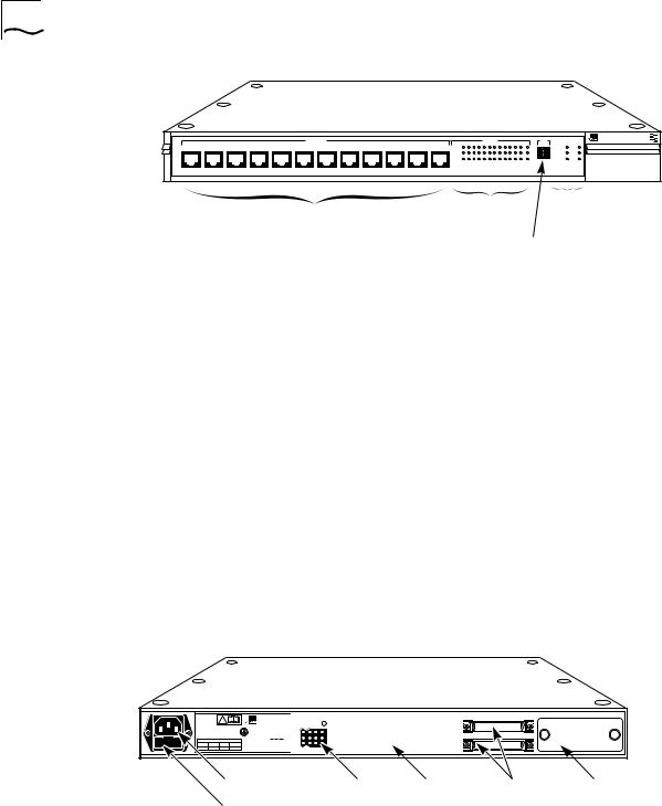
Hub
RJ-45 ports Port LEDs operation
LEDs
Unit digital display
Figure 1-1 Front Panel of LinkBuilder FMS 100-TX Hub
■
■
Each port (including the thirteenth port) is supplied with three LEDs that provide activity, link, and partition status information. Additional LEDs provide repeater classification, environmental, and port status information. (Refer to Chapter 3 for the interpretation of LEDs.)
The hub’s rear panel (Figure 1-2) has a slot for a 3Com transceiver interface module, which (as the thirteenth port) provides media flexibility and accessibility to the hub. This slot can also be left empty, if desired, with no connection (no module attached).
Two types of transceiver interface modules are available and must be purchased separately:
100BASE-TX Category 5 UTP module (3C252-TX)
100BASE-FX Fiber module (3C262-FX)
Additional modules may be supported in the future.
REFER TO
INSTRUCTION MANUAL
FOR CORRECT !
SELECTION OF
POWER CORD
CAUTION: For continued protection against risk of fire use only with same type and rating of anti-serge fuse.
3Com Corporation |
|
|
|
|
|
||||
Santa Clara, CA |
|
|
DC INPUT |
|
|
|
|
||
Made in USA |
|
|
|
|
|
|
|||
|
|
|
|
|
|
|
|
|
|
|
|
|
|
|
|
|
|
|
|
INPUT |
|
|
|
|
|
|
|
|
|
|
|
|
|
|
|
|
|
||
V |
5 |
+12 |
–12 |
D |
|
|
|
E |
|
A max |
5.0 |
2.5 |
0.2 |
|
|
|
|||
|
|
|
|
|
|||||
EXPANSION
UP |
DOWN |
AC power cord socket DC input |
Power-up |
Expansion |
Transceiver |
connector |
disabled |
connectors |
interface |
Fuse compartment |
option switch |
|
module port |
Figure 1-2 Rear Panel of LinkBuilder FMS 100-TX Hub

Management Unit |
1-3 |
The two expansion connectors are used for adding components (additional hubs or a Management Unit) to create a hub stack.The LinkBuilder FMS 100-TX Hub can be used as a stand-alone repeater or as a stacked unit with other LinkBuilder FMS 100 Hubs. Stacking units provides the benefit of a higher port count, with the stack functioning as a single logical repeater. Up to eight units (for example, seven hubs and a Management Unit) can be connected together in a stack.
The rear panel of the hub provides a three-pronged socket for attaching a 100–240 V AC power cord to the hub. Alternatively, power can be supplied through a 3Com Redundant Power System (RPS) connected to the DC input connector. Refer to the section “Using the Redundant Power System” in Chapter 2 for additional information.
A 2 A, 250 V fast-blow fuse is located in the hub’s AC receptacle.
You can mount the LinkBuilder FMS 100-TX Hub in a 19-inch standard rack or you can place it as a stand-alone unit on a desk or table. A rack-mounting kit is supplied with each hub.
Management Unit The LinkBuilder FMS 100-TX Hub can support a Management Unit to provide full SNMP manageability to a hub stack. The Management Unit is designed for inclusion in 3Com’s SuperStack family of stackable network devices and can also be connected to the Redundant Power System (RPS). If a Management Unit is included in a stack, a maximum of seven hubs is allowed in the stack — that is, one Management Unit plus seven repeaters for a total of eight components, the maximum number of components allowed in one hub stack.
Only one Management Unit can be attached to each stack.

1-4 CHAPTER 1: INTRODUCTION
Hub Functions The LinkBuilder FMS 100-TX Hub supports the standard functions of an IEEE 802.3 repeater, as listed in Table 1-1.
Table 1-1 Supported IEEE 802.3 Repeater Functions
Standard Repeater |
|
Function |
Description |
|
|
Signal retiming |
Restores the timing and amplitude of the received signal |
|
before retransmitting the signal. |
Carrier integrity monitor |
Examines the packets being received for invalid framing; |
|
blocks excessive invalid frames to prevent them from |
|
harming the network. |
Jabber control |
Inhibits overly long transmissions of data generated by |
|
station hardware failure. This function is activated once a |
|
received packet has exceeded the jabber threshold. Refer to |
|
the 802.3u specification for additional information. |
Automatic partition/ |
Prevents the faulty segment’s carrier activity from reaching |
reconnection |
the hub and being propagated throughout the network. |
|
|

2 |
INSTALLING THE |
FMS 100-TX HUB |
This chapter discusses the following topics:
■Unpacking the hub
■Positioning the hub
■Installing the hub
■Installing the transceiver interface modules
■Using the Redundant Power System
■Replacing the fuse
Unpacking the |
When unpacking the hub, follow these steps: |
Hub |
|
1Open the shipping container and carefully remove its contents.
2Return all packing materials to the shipping container and save it.
If the hub must be returned, ship it in its original shipping container (or one providing equivalent protection), or the warranty will be voided.
3Verify that you have received all items that are shipped with the hub, as listed below.
4Inspect each item for damage. If you find any omissions or damage, contact your network supplier and the carrier that delivered the package.
Each LinkBuilder FMS 100-TX hub is shipped with the following:
■Rack mounting kit containing two brackets and four screws
■Four rubber feet for desktop placement
■AC power cord

2-2 CHAPTER 2: INSTALLING THE FMS 100-TX HUB
|
If you ordered one or more transceiver interface modules, they will be |
|
packaged separately from the hub. |
|
|
Positioning the |
When deciding where to place the hub, make sure the environment meets |
Hub |
the following conditions: |
■The hub is accessible and cables can be connected easily.
For help in planning your network configuration and the location of the hub, refer to Chapters 3 and 4 for information on connecting the hub to the network and the required cabling types and lengths. Read this material before locating the hub permanently.
■Cabling is away from:
■Sources of electrical noise, such as HVAC, radios, transmitters, and broadband amplifiers
■Power lines and fluorescent lighting fixtures
■Water or moisture cannot enter the hub’s case.
■Airflow around the unit and through the vents is not restricted. Provide a minimum of 1 inch (2.5 cm) clearance on all four sides of the unit.
■No objects are placed directly on top of any stack or unit other than another stackable device.
Installing the Hub This section discusses hub installation. You can install the hub in a standard 19-inch rack or on a desk or table.
WARNING: 3Com strongly recommends that you install the hub stack in a rack, particularly if you intend to use more than four hubs in the stack. Since each hub weighs 12 pounds (5.5 kg), the total weight of eight hubs (the maximum hub stack), plus the possible addition of two RPSs, would be more than 100 pounds (45.5 kg). For maximum safety, this combination of units should be installed in the lower part of a rack. If placed on a desk or table, be certain that the furniture is sturdy enough to support the weight.
Installing the Hub |
2-3 |
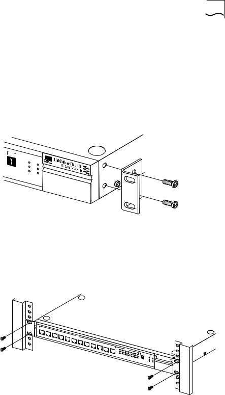
Rack Mounting The hub is supplied with two brackets and four screws for rack mounting in a standard 19-inch rack. The four rubber feet that are shipped with each hub are not used for rack mounting.
To mount the hub in a rack, follow these steps, which assume you are stacking two or more hubs in a rack:
1Place one of the hubs on a level surface, with the front panel facing you.
2Position a bracket over the mounting holes on one side of the unit, as shown in Figure 2-1.
.
UNIT |
3C250-TX/ |
||
FAN |
|||
|
FAIL |
CLSII |
|
OVERTEMP |
|||
CLSI |
|||
COLLISION |
|||
PWR |
|||
|
|
||
®
Figure 2-1 Attaching a Bracket for Rack Mounting
3Insert the two screws and tighten with a screwdriver.
4Repeat steps 2 and 3 for the other side of the hub.
5Mount the hub in the rack and secure it with suitable screws, as shown in Figure 2-2.
1x 2x 3x 4x
5x |
100BT |
|
6x |
7x 8x 9x 10x 11x 12x
ACTIVITY |
|
|
|
STATUS |
|
|
|
|
|
|
||
LINK |
|
|
|
|
|
|
|
|
|
|
|
|
PARTITION |
|
|
|
|
|
|
|
|
|
|
|
|
1 |
2 |
3 |
4 |
|
|
|
|
|
|
|
|
|
|
5 |
6 |
|
|
|
|
|
|
|
|||
|
|
|
|
|
7 |
8 |
9 |
10 |
|
|
|
|
|
|
|
|
|
|
|
|
|
11 |
12 |
13 |
|
|
|
|
|
|
|
|
|
|
|
|
||
UNIT
3C250- |
TX/ |
|
FAN FAIL |
|
|
OVERTEMP |
CLSII |
|
CLSI |
||
COLLISION |
PWR |
|
|
||
LinkBuilder FMS
100BASE-TX
100  Hub
Hub 
Figure 2-2 Rack Mounting a Single Hub

2-4 CHAPTER 2: INSTALLING THE FMS 100-TX HUB
6Attach brackets to both sides of the other hubs to be rack-mounted, as described in steps 2 through 4.
7Insert each hub into the rack and fasten each one individually to the rack uprights, as shown in Figure 2-3.
1x |
|
2x |
|
3x |
|
4x |
100BT |
5x |
|
|
6x |
|
7x |
|
8x |
|
9x |
1x |
10x |
2x |
11x |
3x |
12x |
4x |
100BT |
5x |
|
|
6x |
|
7x |
|
8x |
|
9x |
1x |
10x |
2x |
11x |
3x |
12x |
4x |
100BT |
5x |
|
|
6x |
|
7x |
|
8x |
|
9x |
|
10x |
|
11x |
|
12x |
ACTIVITY |
|
|
|
STATUS |
|
|
|
|
|
|
|
|
||
LINK |
|
|
|
|
|
|
|
|
|
|
|
|
|
|
PARTITION |
|
|
|
|
|
|
|
|
|
|
|
UNIT |
|
|
1 |
2 |
|
|
|
|
|
|
|
|
|
|
|
|
|
|
3 |
4 |
5 |
6 |
|
|
|
|
|
|
3C250- |
TX/Ι |
||
|
|
|
|
|
7 |
8 |
9 |
10 |
|
|
FAN FAIL |
|
||
|
|
|
|
|
|
|
|
11 12 |
13 |
OVERTEMP |
CLSII |
|||
|
|
|
|
|
|
|
|
|
|
|
COLLISION |
CLSI |
||
|
|
|
|
|
|
|
|
|
|
|
|
|
PWR |
|
ACTIVITY |
|
|
|
STATUS |
|
|
|
|
|
|
|
|
||
LINK |
|
|
|
|
|
|
|
|
|
|
|
|||
|
|
|
|
|
|
|
|
|
|
|
|
|
|
|
PARTITION |
|
|
|
|
|
|
|
|
|
|
|
UNIT |
|
|
1 |
2 |
|
|
|
|
|
|
|
|
|
|
|
|
|
|
3 |
4 |
5 |
6 |
|
|
|
|
|
|
3C250- |
TX/Ι |
||
|
|
|
|
|
7 |
8 |
9 |
10 |
|
|
FAN FAIL |
|
||
|
|
|
|
|
|
|
|
11 12 |
13 |
OVERTEMP |
CLSII |
|||
|
|
|
|
|
|
|
|
|
|
CLSI |
||||
|
|
|
|
|
|
|
|
|
|
|
|
COLLISION |
PWR |
|
|
|
|
|
|
|
|
|
|
|
|
|
|
||
ACTIVITY |
|
|
|
STATUS |
|
|
|
|
|
|
|
|
||
LINK |
|
|
|
|
|
|
|
|
|
|
|
|||
PARTITION |
|
|
|
|
|
|
|
|
|
|
|
UNIT |
|
|
1 |
2 |
|
|
|
|
|
|
|
|
|
|
|
|
|
|
3 |
4 |
5 |
6 |
|
|
|
|
|
|
3C250- |
TX/Ι |
||
|
|
|
|
|
7 |
8 |
9 |
10 |
|
|
FAN FAIL |
|
||
|
|
|
|
|
|
|
|
11 12 |
13 |
OVERTEMP |
CLSII |
|||
|
|
|
|
|
|
|
|
|
|
|
COLLISION |
CLSI |
||
|
|
|
|
|
|
|
|
|
|
|
|
|
PWR |
|
LinkBuilder FMS |
100 |
|
100BASE- |
|
|
|
TX Hub |
|
LinkBuilder FMS |
100 |
|
100BASE- |
|
|
|
TX Hub |
|
LinkBuilder FMS |
100 |
|
100BASE- |
|
|
|
TX Hub |
|
Figure 2-3 Installing a Hub Stack in a Rack
8Repeat steps 2 through 7 when placing additional hubs in the stack.
A single hub stack can contain up to eight units (eight hubs, or seven hubs and one Management Unit) and two Redundant Power Systems.
9For each hub, plug one end of the power cord into the AC power connector and the other end into a power source. (Refer to the section “Using the Redundant Power System” for information on installing the Redundant Power System.)
All the LEDs should light momentarily. Verify that the PWR (power) LED remains ON, indicating that the hub is receiving power.
See Chapter 3 for information about connecting the stack to the network
and interpreting LEDs.

Installing the Transceiver Interface Modules |
2-5 |
Desktop Placement If you place the hub on a desk or table, attach the supplied rubber feet to each bottom corner of the hub. If you stack additional hubs on top of the bottom one, place rubber feet on the bottom of each corner of each hub in the outline shown on the unit’s base.
To prevent hubs from possibly sliding off the stack, fasten each hub to the hub below it by using the supplied brackets, as shown in Figure 2-4.
 UNIT
UNIT
FAN |
3C250-TX/ |
||
FAIL |
Ι |
||
|
CLSII |
||
OVERTEMP |
|||
CLSI |
|||
COLLISION |
|||
PWR |
|||
|
|
||
®
 UNIT
UNIT
FAN |
3C250-TX/ |
||
FAIL |
Ι |
||
|
CLSII |
||
OVERTEMP |
|||
CLSI |
|||
COLLISION |
|||
PWR |
|||
|
|
||
®
|
Figure 2-4 Attaching a Bracket for Desktop Placement |
|
||
|
|
|||
Installing the |
The LinkBuilder FMS 100-TX Hub chassis is equipped with a rear panel port |
|||
Transceiver |
into which you can insert an optional 3Com transceiver interface module. |
|||
Interface Modules |
The transceiver interface module permits connections to a 100 Mbps Ethernet |
|||
|
station or a network backbone that is also running 100 Mbps Ethernet. |
|||
|
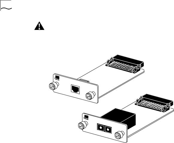
The two types of transceiver interface modules are shown in Figure 2-5. |
|||
|
Table 2-1 describes the two 100 Mbps modules. |
|
||
|
Table 2-1 Transceiver Interface Modules |
|
|
|
|
|
|
|
|
|
Module Type |
3Com Part Number |
Connector |
Cabling |
|
|
|
|
|
|
100BASE-TX |
3C252-TX |
RJ-45 |
Category 5 UTP cabling |
|
100BASE-FX |
3C262-FX |
Multimode fiber |
Two-strand (62.5/125 ) |
|
|
|
SC connector |
fiber-optic cabling |
|
|
|
|
|
2-6 CHAPTER 2: INSTALLING THE FMS 100-TX HUB
CAUTION: Each module is packed in antistatic material to protect it during shipment. To avoid damaging any static-sensitive components after removal from the container, be sure to reduce any static electricity on your person.
One way to do this is to touch the metal chassis of the hub. You can maintain grounding by wearing a wrist strap attached to the chassis.
®
100BASE-TX
100BASE-TX
®
100BASE-FX
100BASE-FX
Figure 2-5 Transceiver Interface Modules
To install a transceiver interface module, follow these steps:
1Disconnect the AC power cord from the individual hub into which you are installing the transceiver interface module.
You do not have to power down the entire stack to install a module in a single hub. If you are installing several modules, power down each hub before inserting its module.
2Remove the blanking plate from the transceiver interface module port on the hub’s rear panel by unscrewing the plate’s two end screws.
The transceiver interface module port is shown in Figure 1-2.
Keep the blanking plate for possible future use in case you remove the
module.
Loading...