


OfficeConnect®
Ethernet Hub 4, 4C, 8, 8C
User Guide (3C16704A, 3C16703A, 3C16700A, 3C16701A)

3Com Corporation ■ 5400 Bayfront Plaza ■ Santa Clara, California ■ 95052-8145
Copyright © 1999, 3Com Technologies. All rights reserved.
No part of this documentation may be reproduced in any form or by any means or used to make any derivative work (such as translation, transformation, or adaptation) without written permission from 3Com Technologies.
3Com Technologies reserves the right to revise this documentation and to make changes in content from time to time without obligation on the part of 3Com Technologies to provide notification of such revision or change.
3Com Technologies provides this documentation without warranty, term, or condition of any kind, either implied or expressed, including, but not limited to, the implied warranties, terms or conditions of merchantability, satisfactory quality, and fitness for a particular purpose. 3Com may make improvements or changes in the product(s) and/or the program(s) described in this documentation at any time.
If there is any software on removable media described in this documentation, it is furnished under a license agreement included with the product as a separate document, in the hard copy documentation, or on the removable media in a directory file named LICENSE.TXT or !LICENSE.TXT. If you are unable to locate a copy, please contact 3Com and a copy will be provided to you.
UNITED STATES GOVERNMENT LEGEND
If you are a United States government agency, then this documentation and the software described herein are provided to you subject to the following:
All technical data and computer software are commercial in nature and developed solely at private expense. Software is delivered as “Commercial Computer Software” as defined in DFARS 252.227-7014 (June 1995) or as a “commercial item” as defined in FAR 2.101(a) and as such is provided with only such rights as are provided in 3Com’s standard commercial license for the Software. Technical data is provided with limited rights only as provided in DFAR 252.227-7015 (Nov 1995) or FAR 52.227-14 (June 1987), whichever is applicable. You agree not to remove or deface any portion of any legend provided on any licensed program or documentation contained in, or delivered to you in conjunction with, this User Guide.
Unless otherwise indicated, 3Com registered trademarks are registered in the United States and may or may not be registered in other countries.
3Com, the 3Com logo and OfficeConnect are registered trademarks of 3Com Corporation.
Microsoft, MS-DOS, Windows, and Windows NT are registered trademarks of Microsoft Corporation. Novell and NetWare are registered trademarks of Novell, Inc.
All other company and product names may be trademarks of the respective companies with which they are associated.
Year 2000 Compliance: For information on Year 2000 compliance and 3Com products, visit the 3Com Year 2000 Web page: http://www.3com.com/products/yr2000.html
Environmental Statement: Please recycle this user guide after use.
Please e-mail any comments about this document to 3Com at: pddtechpubs_comments@3Com.com. Please include the document title (OfficeConnect Ethernet Hub 4, Hub 4C, Hub 8, Hub 8C), part number (DUA1670-0AAA04) and, if appropriate, the page number.

Introduction 5
Creating your Network 6
What Else Do I Need? 6 Workstation Connections 6 Transceiver Connections 6 Hub Connections 7 10BASE-2 7
10BASE-T 7
Twisted Pair (TP) Cables 7 Stacking the Units Together 8
The Rubber Feet 8
The Stacking Clip 8 Positioning Your Hub 9 Securing Your Hub 9 Using Your Hub 9
The OfficeConnect Ethernet Hub 4 and 4C 10
Ethernet Hub 4 and 4C—Front 10
Ethernet Hub 4 and 4C—Rear 11
Connecting Workstations and Other Equipment to Your Hub 12 Connecting Transceivers to the AUI Port 12
Connecting OfficeConnect Ethernet Hubs Together 12 Connecting Hubs Using 10BASE-2 13
Checking Connections 13 Connecting Hubs Using 10BASE-T 14 Checking Connections 14
Spot Checks 14
Problem Solving for the Hub 4 and 4C 15
The OfficeConnect Ethernet Hub 8 and 8C 17
Ethernet Hub 8 and 8C—Front 17
Ethernet Hub 8 and 8C—Rear 18
Connecting Workstations and Other Equipment to Your Hub 19 Connecting OfficeConnect Ethernet Hubs Together 19
Connecting Hubs Using 10BASE-2 20 Checking Connections 20 Connecting Hubs Using 10BASE-T 21 Checking Connections 21
Spot Checks 21
Problem Solving for the Hub 8 and 8C 22
Networking Terminology 24
Dimensions and Standards 25
Dimensions and Operating Conditions 25
Standards 25
Environmental Statements 26
End Of Life Statement 26 Regulated Materials Statement 26
Environmental Statement about the Documentation 26 Environmental Statement about the Product Packaging 26
Important Safety Information 27
Wichtige Sicherheitshinweise 28
3

Consignes importantes de sécurité 29
Technical Support 30
Online Technical Services 30 World Wide Web Site 30
3Com Knowledgebase Web Services 30 Support from Your Network Supplier 31 Support from 3Com 31
Returning Products for Repair 34
3Com Corporation Limited Warranty 35
Electromagnetic Compatibility 38
4
INTRODUCTION
Welcome to the world of networking with 3Com® . In the modern business environment, communication and sharing information is crucial. Computer networks have proved to be one of the fastest modes of communication but, until recently, only large businesses could afford the advantage of networking. The OfficeConnect® product range from 3Com has changed this, bringing networks into the small office.
The OfficeConnect Ethernet Hub 4, OfficeConnect Ethernet Hub 4C, OfficeConnect Ethernet Hub 8 and OfficeConnect Ethernet Hub 8C, are ideal for creating small networks. They are compact and attractively designed for desktop use.
These four products are part of the OfficeConnect range which stack neatly together with the OfficeConnect stacking clip.
This user guide describes how to use the OfficeConnect hubs. The hubs have similar features and so this user guide contains general and specific information. When referring to all products, this guide uses the term ‘OfficeConnect hub’.
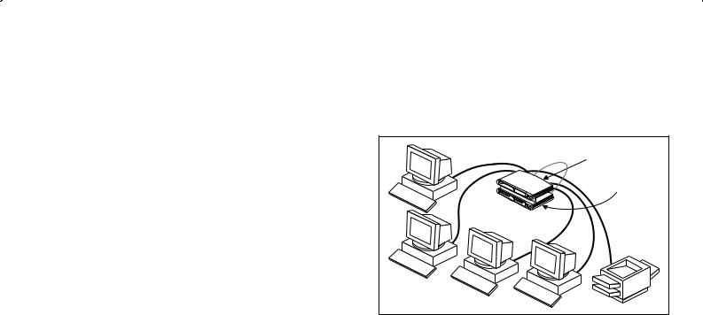
A single OfficeConnect hub allows you to create a small network with up to four or eight workstations, as shown in Figure 1. If you need to connect more workstations, simply use the stacking clip to connect another OfficeConnect hub to form a stack (each hub is a single repeater).
Figure 1 Small Network With OfficeConnect Hub and Optional Print Server
HP JetDirect |
OfficeConnect |
print server |
OfficeConnect hub |
The OfficeConnect hubs have the following ports:
■The Ethernet Hub 4 has four 10BASE-T ports.
■The Ethernet Hub 4C has four 10BASE-T ports, a 10BASE-2 port and an AUI port.
■The Ethernet Hub 8 has eight 10BASE-T ports.
■The Ethernet Hub 8C has eight 10BASE-T ports and a ninth 10BASE-2 port.
5

CREATING YOUR NETWORK
What Else Do I Need?
Your OfficeConnect hub comes with:
■One power adapter for use with the OfficeConnect hub.
■A Product Registration card for you to fill out and return.
■Four rubber feet.
■A stacking clip.
■Two unit labels and eight cable ties.
■An OfficeConnect Network Assistant CD-ROM.
To connect workstations and additional OfficeConnect hubs to your hub, you need extra equipment. The extra equipment listed in the next section is not provided with the hub.
Workstation Connections
To connect workstations and other equipment to your hub, you need:
110BASE-T connections for all your equipment. 3Com produce a range of easy to install network adapter cards, which provide your workstations with 10BASE-T connections.
3
2 
 1
1
2An operating system (for example, Netware or Windows 95/98) with network support configured, running on your workstations.
3One straight-through TP cable for every workstation, as shown in Figure 2.
In order to comply with the 10BASE-T standard, ports designed for workstation connections have been marked with the graphical symbol ‘x’. This denotes a crossover in the port’s internal wiring, for example 1x, 2x, 3x...
Transceiver Connections
If you want to connect a transceiver to your hub (Hub 4C only), you need:
■An AUI cable. The maximum length you can use is 50m (164ft).
■A 10Mbps Ethernet transceiver for the chosen media type. 3Com produce a range of easy to use transceivers.
6

Hub Connections
Depending on what ports your hub has, you can use either 10BASE-T or 10BASE-2 to connect your hubs together:
■With 10BASE-2 you can connect up to 30 hubs on a single segment, leaving all of the 10BASE-T ports free.
■With 10BASE-T you can connect up to four hubs in series.
10BASE-2
To connect additional hubs using 10BASE-2 (Hub 4C and 8C only), you need (as shown in Figure 2):
■One 10BASE-2 50 Ohm cable for each additional hub. The minimum cable length you can use is 0.5m (1.6ft). The maximum segment length is 185m (607ft).
■One 10BASE-2 ‘Y’ piece for each hub. You can use ‘T’ pieces but ‘Y’ pieces provide optimal clearance of the other ports.
■Two 10BASE-2 50 Ohm terminators (end pieces).
Figure 2 Some of the 10BASE-2 Equipment You May Need
|
|
or |
Terminator |
|
|
(end piece) |
‘Y’ piece |
‘T’ piece |
10BASE-T
If you have additional hubs you want to connect using 10BASE-T, you need:
■ One straight-through TP cable for each extra hub.
Twisted Pair (TP) Cables
To connect your workstations and hubs, you must use straight-through TP cable with RJ-45 connectors. Cables can be shielded (screened) or unshielded; we recommend that you use shielded. The maximum length you can use is 100m (328ft). A straight-through cable is one where the pins of one connector are connected to the same pins of the other connector.
7

Stacking the Units Together
The Rubber Feet
The four self-adhesive rubber feet prevent your hub from moving around on your desk. Only stick the feet to the marked areas at each corner of the underside of your hub if you intend to place the unit directly on top of the desk. Do not fix the feet if you are going to use the clip.
The Stacking Clip
The blue stacking clip allows you to stack your OfficeConnect units together securely.
CAUTION: You can stack up to a maximum of four units. Smaller units must be stacked above larger units.
To fit the clip:
1Place your unit on a flat surface.
2Fit the clip across the top of the unit, as shown in Figure 3 (picture 1), ensuring that the longer sections of the fastening pieces are pointing downwards.
3Align the fastening pieces over the slots found on each side of the unit.
4Push the clip down gently to secure it, ensuring the fastening pieces snap into the slots on the unit.
To fit another unit:
1Rest the second unit on top of the clip and align it with the front of the unit below.
2Press down gently on the unit to secure it onto the clip, ensuring the fastening pieces fit into the slots on the unit below, as shown in Figure 3 (picture 2).
Figure 3 Stacking Your Units Together
1 |
Fastening |
2 |
|
|
|
|
Piece |
|
|
|
Fastening |
|
|
Piece |
To remove the clip:
1Remove the top unit together with the clip. If you hook a finger around one of the the fastening pieces and then pull it gently from out of the slot, the clip should come away with the upper unit attached to it.
2Push the clip in the center, so it bends towards the base of the unit, and then separate once the clip is loose.
8

Positioning Your Hub
When installing your OfficeConnect hub, ensure:
■It is out of direct sunlight and away from sources of heat.
■Cabling is away from power lines, fluorescent lighting fixtures, and sources of electrical noise such as radios, transmitters and broadband amplifiers.
■Water or moisture cannot enter the case of the unit.
■Air flow around the unit and through the vents in the side of the case is not restricted. We recommend you provide a minimum of 25.4mm (1in.) clearance.
Securing Your Hub
There are two slots on the underside of the OfficeConnect hub which can be used for wall mounting. It is recommended that you mount the hubs with the LEDs facing upwards to prevent dust entering the cooling vents.
When wall mounting your hub, ensure that it is within reach of the power outlet.
You need two suitable screws. Ensure that the wall you are going to use is smooth, flat, dry and sturdy. Make two screw holes which are 150mm (5.9in.) apart. Use the template at the back of this guide to mark the position of the holes. Fix the screws into the wall, leaving their heads 3mm (0.12in.) clear of the wall surface.
Remove any connections to the hub and locate it over the screw heads. When in line, gently push the hub on to the wall and move it downwards to secure. When making connections, be careful not to push the hub up and off the wall.
CAUTION: Only wall mount single hubs, do not wall mount stacked hubs.
Also available from 3Com, is the OfficeConnect Mounting Unit (part number 3C16765). This allows you to firmly secure a stack of OfficeConnect devices to the desktop or onto a shelf in a rack.
Using Your Hub
You are now ready to create your network, using your OfficeConnect hub.
Read pages 10–16 if you have an:
■ OfficeConnect Ethernet Hub 4 or Hub 4C
Read pages 17–23 if you have an:
■ OfficeConnect Ethernet Hub 8 or 8C
When you have connected your equipment, you are ready to use your network. If you suspect there is a problem, refer to (depending on your hub):
■“Problem Solving for the Hub 4 and 4C” on page 15
■“Problem Solving for the Hub 8 and 8C” on page 22
9
THE OFFICECONNECT ETHERNET HUB 4 AND 4C
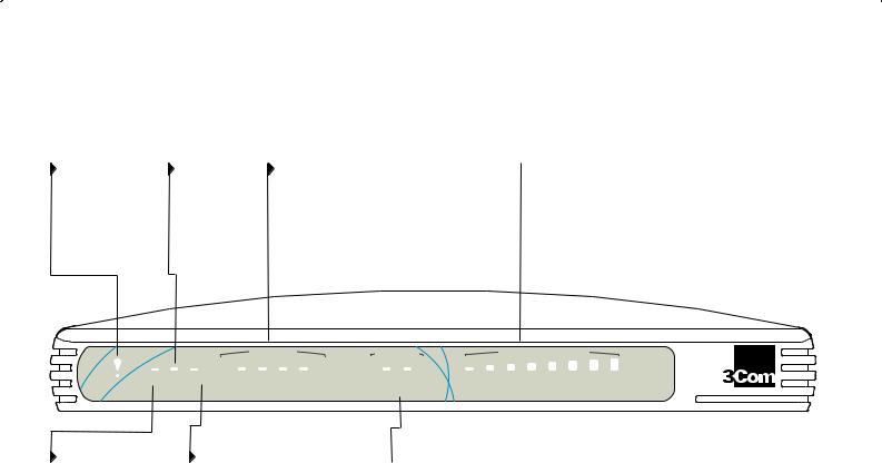
Ethernet Hub 4 and 4C—Front
Alert LED |
Activity LED |
10BASE-T Port Status LEDs |
orange |
(Hub 4 only) |
green/yellow |
Alerts you to excessive |
yellow |
Indicates the status of each 10BASE-T port. |
network use or an |
Flashes each time |
green — The link between the port and the next |
isolated (partitioned) |
a packet is |
piece of network equipment is OK. |
10BASE-T port. |
received on a |
yellow — The port has partitioned due to a fault on |
|
port. |
that segment. |
|
|
off — Nothing is connected to the port or the link |
|
|
has failed. |
 Network Utilization LEDs (Hub 4C only) green/yellow/orange
Indicates how much your network is being used.
|
|
|
Port Status |
|
AUI/COAX |
Network Utilization |
||
Alert |
Power ActivityCollision |
1 |
2 |
3 |
4 |
Green=AUI |
Partitioned |
1% 2% 3% 6% 12% 25% 50% 80% |
|
|
Green = OK, Yellow = Partitioned |
|
|||||
|
|
off=COAX |
|
OfficeConnect Ethernet Hub 4C |
||||
Power LED |
Collision LED |
green |
yellow |
Indicates that the hub is |
Flashes each time a collision is detected |
powered on. |
on the network. Collisions are part of |
|
normal network operation. |
 AUI/COAX Status LEDs (Hub 4C only) green/off=media, yellow=partition
Indicates the status of the AUI or 10BASE-2 port, depending on which one is in use. green/off — The left-hand status LED is green if the AUI port is in use, and off if either the 10BASE-2 port is being used or nothing is connected to the port.
yellow — If the right-hand status LED is yellow, the port in use has been partitioned.
10
Ethernet Hub 4 and 4C—Rear
Power Adapter socket |
AUI port (Hub 4C only) |
Four 10BASE-T RJ-45 ports |
Only use the power adapter that is supplied with |
Allows 10Mbps transceivers of different media types |
Use 10BASE-T cable with RJ-45 |
this OfficeConnect hub. Do not use any other |
to be connected to the hub. Connecting a |
connectors. You can connect the |
adapter. |
transceiver automatically disables the 10BASE-2 |
OfficeConnect hub to any workstation |
|
port. |
or piece of equipment that has a |
|
|
10BASE-T port. Refer to “Connecting |
|
|
Hubs Using 10BASE-T” on page 14. |
|
|
Uplink |
|
|
|
Normal |
1x |
|
|
4 |
|
POWER |
COAX |
AUI |
|
10BASE-2 port (Hub 4C only) |
Uplink/Normal switch |
Can be used to connect your hub to other OfficeConnect hubs and equipment with 10BASE-2 cabling.
If used, it is effectively a fifth port. Refer to “Connecting Hubs Using 10BASE-2” on page 13.
Affects the operation of port 4. For correct usage, refer to “Connecting Hubs Using 10BASE-T” on page 14.
11

Connecting Workstations and Other Equipment to Your Hub
WARNING: Please read the ‘Important Safety Information’ section before you start.
WARNHINWEIS: Bitte lesen Sie den Abschnitt ‘Wichtige Sicherheitsinformationen’ sorgfältig durch, bevor Sie das Gerät einschalten.
AVERTISSEMENT: Veuillez lire attentivement la section “Consignes importantes de sécurité” avant de mettre en route.
CAUTION: Do not power the hub off and on quickly. Wait about five seconds between power cycles.
Connect workstations and other equipment to any of the hub’s 10BASE-T RJ-45 ports using 10BASE-T cables.
To connect a 10BASE-T cable, simply slot the connector into the relevant RJ-45 port. When the connector is fully in, its latch locks it into place. To disconnect the cable, push the connector’s latch in and remove it.
If you are using port 4 to connect to a workstation using a straight-through TP cable, ensure the Uplink/Normal switch is set to Normal (out).
The hub detects all port connections, so you can start using your network immediately. When you need more ports, simply add more OfficeConnect hubs.
Connecting Transceivers to the AUI Port
You can connect a 10Mbps Ethernet transceiver to your hub (Hub 4C only), using a standard AUI cable. Connect one end of the cable to the transceiver and the other end to the AUI port on the hub’s rear panel. This automatically disables the 10BASE-2 port, and activates the AUI/COAX LED to show the external transceiver is in use. Engage the slide locks at both ends of the AUI cable.
Connecting OfficeConnect Ethernet Hubs
Together
You can increase the number of workstations that can connect to your network by adding more OfficeConnect hubs. You can use either 10BASE-T or 10BASE-2 (Hub 4C only) to do this.
Do not connect the same two hubs together using both 10BASE-T and 10BASE-2. This causes a network loop.
If you do not use the 10BASE-2 port, you do not need to connect a terminator (end piece) to it. If the AUI port is not used and a terminator is not connected to the 10BASE-2 port, the port partitions and the Coax Status LED lights yellow. This is correct operation.
12
 Loading...