


 Loading...
Switch 7750
Configuration Guide
Version 3.1.5
http://www.3com.com/
Published August 2005
Part No.10014298
3Com Corporation |
Copyright © 2005, 3Com Corporation. All rights reserved. No part of this documentation may be reproduced |
350 Campus Drive |
in any form or by any means or used to make any derivative work (such as translation, transformation, or |
Marlborough, MA |
adaptation) without written permission from 3Com Corporation. |
01752-3064 |
3Com Corporation reserves the right to revise this documentation and to make changes in content from time |
|
|
|
to time without obligation on the part of 3Com Corporation to provide notification of such revision or change. |
|
3Com Corporation provides this documentation without warranty, term, or condition of any kind, either |
|
implied or expressed, including, but not limited to, the implied warranties, terms or conditions of |
|
merchantability, satisfactory quality, and fitness for a particular purpose. 3Com may make improvements or |
|
changes in the product(s) and/or the program(s) described in this documentation at any time. |
|
If there is any software on removable media described in this documentation, it is furnished under a license |
|
agreement included with the product as a separate document, in the hard copy documentation, or on the |
|
removable media in a directory file named LICENSE.TXT or !LICENSE.TXT. If you are unable to locate a copy, |
|
please contact 3Com and a copy will be provided to you. |
|
UNITED STATES GOVERNMENT LEGEND |
|
If you are a United States government agency, then this documentation and the software described herein |
|
are provided to you subject to the following: |
|
All technical data and computer software are commercial in nature and developed solely at private expense. |
|
Software is delivered as “Commercial Computer Software” as defined in DFARS 252.227-7014 (June 1995) |
|
or as a “commercial item” as defined in FAR 2.101(a) and as such is provided with only such rights as are |
|
provided in 3Com’s standard commercial license for the Software. Technical data is provided with limited |
|
rights only as provided in DFAR 252.227-7015 (Nov 1995) or FAR 52.227-14 (June 1987), whichever is |
|
applicable. You agree not to remove or deface any portion of any legend provided on any licensed program |
|
or documentation contained in, or delivered to you in conjunction with, this User Guide. |
|
Unless otherwise indicated, 3Com registered trademarks are registered in the United States and may or may |
|
not be registered in other countries. |
|
3Com, the 3Com logo, are registered trademarks of 3Com Corporation. |
|
Intel and Pentium are registered trademarks of Intel Corporation. Microsoft, MS-DOS, Windows, and |
|
Windows NT are registered trademarks of Microsoft Corporation. UNIX is a registered trademark in the United |
|
States and other countries, licensed exclusively through X/Open Company, Ltd. |
|
All other company and product names may be trademarks of the respective companies with which they are |
|
associated. |

CONTENTS
ABOUT THIS GUIDE
Conventions 9
SYSTEM ACCESS
Product Overview |
11 |
|
|
|
|
|
Features 11 |
|
|
|
|
|
|
Configuring the Switch 7750 |
12 |
|
|
|
||
Setting Terminal Parameters |
13 |
|
|
|
||
Configuring Through Telnet |
16 |
|
|
|||
Configuring Through a Dial-up Modem |
18 |
|||||
Configuring the User Interface |
20 |
|
|
|||
Command Line Interface |
28 |
|
|
|
|
|
Command Line View |
28 |
|
|
|
|
|
Features and Functions of the Command Line 31 |
||||||
|
|
|
|
|
||
PORT CONFIGURATION |
|
|
|
|
||
Ethernet Port Overview |
35 |
|
|
|
|
|
Configuring Ethernet Ports |
35 |
|
|
|
||
Troubleshooting VLAN Port Configuration |
42 |
|||||
Configuring Link Aggregation |
42 |
|
|
|
||
Types of Link Aggregation |
43 |
|
|
|
||
Load Sharing |
45 |
|
|
|
|
|
Configuring Link Aggregation |
46 |
|
|
|||
|
|
|
|
|
||
VLAN CONFIGURATION |
|
|
|
|
||
VLAN Overview |
53 |
|
|
|
|
|
Configuring VLANs 53 |
|
|
|
|
|
|
Common VLAN Configuration Tasks |
54 |
|
||||
Configuring Port-Based VLANs |
57 |
|
|
|||
Configuring Protocol-Based VLANs |
57 |
|
||||
Configuring GARP/GVRP |
61 |
|
|
|
|
|
Configuring GVRP |
63 |
|
|
|
|
|
|
|
|
||||
NETWORK PROTOCOL OPERATION |
|
|
||||
Configuring IP Address |
67 |
|
|
|
|
|
Subnet and Mask |
68 |
|
|
|
|
||
Configuring an IP Address |
68 |
|
|
||||
Troubleshooting an IP Address Configuration |
70 |
||||||
Configuring Address Resolution Protocol (ARP) |
70 |
||||||
Configuring ARP |
71 |
|
|
|
|
||
DHCP Relay |
72 |
|
|
|
|
|
|
Configuring DHCP Relay |
73 |
|
|
||||
Troubleshooting a DHCP Relay Configuration |
76 |
||||||
IP Performance |
|
77 |
|
|
|
|
|
Configuring TCP Attributes |
77 |
|
|
||||
Configuring Special IP Packet Transmission to the CPU 77 |
|||||||
Configuring L3 Broadcast Forwarding 78 |
|
||||||
Displaying and Debugging IP Performance |
78 |
||||||
Troubleshooting IP Performance |
79 |
|
|||||
|
|
||||||
IP ROUTING PROTOCOL OPERATION |
|
||||||
IP Routing Protocol Overview |
81 |
|
|
||||
Selecting Routes Through the Routing Table |
82 |
||||||
Routing Management Policy |
83 |
|
|||||
Static Routes |
84 |
|
|
|
|
|
|
Configuring Static Routes |
85 |
|
|
||||
Troubleshooting Static Routes |
88 |
|
|||||
RIP 89 |
|
|
|
|
|
|
|
Configuring RIP 90 |
|
|
|
|
|||
Troubleshooting RIP |
98 |
|
|
|
|||
IP Routing Policy |
99 |
|
|
|
|
|
|
Routing Information Filters |
99 |
|
|
||||
Configuring an IP Routing Policy |
100 |
|
|||||
Troubleshooting Routing Policies |
104 |
|
|||||
Route Capacity |
105 |
|
|
|
|
|
|
Configuring Route Capacity |
105 |
|
|||||
|
|
|
|
|
|||
MULTICAST PROTOCOL |
|
|
|
|
|||
IP Multicast Overview |
109 |
|
|
|
|||
Multicast Addresses |
110 |
|
|
|
|||
IP Multicast Protocols |
112 |
|
|
|
|||
Forwarding IP Multicast Packets |
113 |
|
|||||
Applying Multicast |
114 |
|
|
|
|||
Configuring Common Multicast |
114 |
|
|||||
Configuring Common Multicast |
114 |
|
|||||
Configuring IGMP |
116 |
|
|
|
|
||
Configuring IGMP |
117 |
|
|
|
|||
IGMP Snooping |
124 |
|
|
|
|
|
|
Configuring IGMP Snooping |
127 |
|
|||||
Troubleshooting IGMP Snooping |
129 |
|
|||||
Configuring PIM-DM |
130 |
|
|
|
|||
Configuring PIM-DM |
131 |
|
|
|
|
|||
Configuring PIM-SM |
136 |
|
|
|
|
|
||
PIM-SM Operating Principles |
136 |
|
|
|
||||
Preparing to Configure PIM-SM |
137 |
|
|
|
||||
Configuring PIM-SM |
138 |
|
|
|
|
|||
GMRP 146 |
|
|
|
|
|
|
|
|
Configuring GMRP |
146 |
|
|
|
|
|
||
|
|
|
|
|
|
|
||
QOS/ OPERATION |
|
|
|
|
|
|
||
ACL Overview |
149 |
|
|
|
|
|
|
|
Filtering or Classifying Data Transmitted by the Hardware |
149 |
|||||||
Filtering or Classifying Data Transmitted by the Software |
150 |
|||||||
ACL Support on the Switch 7750 150 |
|
|
||||||
Configuring ACLs |
151 |
|
|
|
|
|
|
|
Configuring the Time Range |
151 |
|
|
|
||||
Selecting the ACL Mode |
151 |
|
|
|
|
|||
Defining an ACL |
151 |
|
|
|
|
|
||
Activating an ACL 154 |
|
|
|
|
|
|||
ACL Configuration Examples |
155 |
|
|
|
||||
Access Control |
155 |
|
|
|
|
|
|
|
Basic ACL |
156 |
|
|
|
|
|
|
|
Link ACL 157 |
|
|
|
|
|
|
|
|
Configuring QoS 157 |
|
|
|
|
|
|
||
Qos Concepts |
158 |
|
|
|
|
|
|
|
Configuring QoS |
161 |
|
|
|
|
|
||
QoS Configuration Examples |
168 |
|
|
|
||||
Configuring ACL Control |
175 |
|
|
|
|
|||
Configuring ACL Control for TELNET Users |
176 |
|
||||||
Configuring ACL Control for SNMP Users |
177 |
|
||||||
|
|
|
|
|
|
|
|
|
STP OPERATION |
|
|
|
|
|
|
|
|
STP Overview |
181 |
|
|
|
|
|
|
|
Configuring STP |
181 |
|
|
|
|
|
|
|
Designating Switches and Ports |
182 |
|
|
|
||||
Calculating the STP Algorithm |
182 |
|
|
|
||||
Generating the Configuration BPDU |
183 |
|
|
|||||
Selecting the Optimum Configuration BPDU |
183 |
|
||||||
Designating the Root Port |
183 |
|
|
|
||||
Configuring the BPDU Forwarding Mechanism 185 |
|
|||||||
MSTP Overview |
186 |
|
|
|
|
|
|
|
MSTP Concepts |
186 |
|
|
|
|
|
||
MSTP Principles |
189 |
|
|
|
|
|
||
Configuring MSTP |
189 |
|
|
|
|
|
|
|
Configuring the MST Region for a Switch |
190 |
|
||||||
Specifying the Switch as Primary or Secondary Root Switch |
191 |
|||||||
Configuring the MSTP Running Mode |
192 |
|
||||||
Configuring the Bridge Priority for a Switch |
193 |
|
|
|||||||
Configuring the Max Hops in an MST Region |
194 |
|
|
|||||||
Configuring the Switching Network Diameter |
194 |
|
|
|||||||
Configuring the Time Parameters of a Switch |
195 |
|
|
|||||||
Configuring the Max Transmission Speed on a Port 196 |
|
|
||||||||
Configuring a Port as an Edge Port |
197 |
|
|
|
||||||
Configuring the Path Cost of a Port |
|
198 |
|
|
|
|||||
Configuring the Priority of a Port |
200 |
|
|
|
||||||
Configuring the Port Connection with the Point-to-Point Link |
201 |
|
||||||||
Configuring the mCheck Variable of a Port |
202 |
|
|
|||||||
Configuring the Switch Security Function 202 |
|
|
||||||||
Enabling MSTP on the Device |
204 |
|
|
|
|
|||||
Enabling or Disabling MSTP on a Port |
204 |
|
|
|
||||||
Displaying and Debugging MSTP |
205 |
|
|
|
||||||
Digest Snooping |
205 |
|
|
|
|
|
|
|
||
Configuring Digest Snooping |
205 |
|
|
|
|
|||||
|
|
|
|
|
||||||
AAA AND RADIUS OPERATION |
|
|
|
|
||||||
IEEE 802.1x |
207 |
|
|
|
|
|
|
|
|
|
802.1x System Architecture |
207 |
|
|
|
|
|
||||
Configuring 802.1x |
209 |
|
|
|
|
|
|
|||
Implementing the AAA and RADIUS Protocols |
215 |
|
|
|||||||
Configuring AAA |
217 |
|
|
|
|
|
|
|
||
Configuring the RADIUS Protocol |
220 |
|
|
|
|
|||||
Configuring HWTACACS |
230 |
|
|
|
|
|
|
|||
Displaying and Debugging the AAA, RADIUS, and HWTACACS Protocols |
237 |
|||||||||
AAA, RADIUS, and HWTACACS Protocol Configuration Examples |
238 |
|
||||||||
Configuring FTP/Telnet User Authentication at Remote RADIUS Server |
238 |
|||||||||
Configuring FTP/Telnet User Authentication at the Local RADIUS Server |
239 |
|||||||||
Configuring the FTP/Telnet User Authentication at a Remote TACACS Server 239 |
||||||||||
Dynamic VLAN with RADIUS Server Configuration Example |
240 |
|
||||||||
Troubleshooting AAA, RADIUS, and HWTACACS Configurations |
241 |
|
||||||||
|
|
|
|
|
|
|
||||
SYSTEM MANAGEMENT |
|
|
|
|
|
|
||||
File System |
243 |
|
|
|
|
|
|
|
|
|
Using a Directory 243 |
|
|
|
|
|
|
||||
Managing Files |
244 |
|
|
|
|
|
|
|
||
Formatting Storage Devices |
244 |
|
|
|
|
|
||||
Setting the Prompt Mode of the File System |
244 |
|
|
|||||||
Configuring File Management |
245 |
|
|
|
|
|||||
FTP |
246 |
|
|
|
|
|
|
|
|
|
TFTP |
248 |
|
|
|
|
|
|
|
|
|
Managing the MAC Address Table 249 |
|
|
|
|
||||||
Configuring the MAC Address Table |
250 |
|
|
|
||||||
Managing Devices |
253 |
|
|
|
|
|
|
|
||
Designating the APP for the Next Boot |
254 |
|
|
|||||||
Displaying Devices |
255 |
|
|
|
Maintaining and Debugging the System |
255 |
|||
Configuring System Basics |
256 |
|
||
Displaying System Information and State 257 |
||||
Debugging the System 257 |
|
|||
Testing Tools for Network Connection |
259 |
|||
Logging Function |
260 |
|
|
|
SNMP |
265 |
|
|
|
SNMP Versions and Supported MIB |
266 |
|||
Configuring SNMP |
267 |
|
|
|
RMON |
274 |
|
|
|
Configuring RMON |
274 |
|
|
|
NTP |
278 |
|
|
|
Configuring NTP |
279 |
|
|
|
NTP Configuration Examples |
286 |
|
||
ABOUT THIS GUIDE
This guide describes the 3Com® Switch 7750 and how to configure it in version 3.0 of the software.
Conventions |
Table 1 lists icon conventions that are used throughout this book. |
||
|
Table 1 |
Notice Icons |
|
|
|
|
|
|
Icon |
Notice Type |
Description |
|
|
|
|
|
|
Information |
Information that describes important features or |
|
|
note |
instructions. |
|
|
Caution |
Information that alerts you to potential loss of data |
|
|
|
or potential damage to an application, system, or |
|
|
|
device. |
|
|
Warning |
Information that alerts you to potential personal |
|
|
|
injury. |
|
|
|
|
Table 2 lists the text conventions used in this book.
Table 2 Text Conventions
Convention |
Description |
|
|
Screen displays |
This typeface represents information as |
|
it appears on the screen. |
Keyboard key names |
If you must press two or more keys |
|
simultaneously, the key names are |
|
linked with a plus sign (+), for example: |
|
Press Ctrl+Alt+Del |
The words “enter” and type” |
When you see the word “enter” in this |
|
guide, you must type something, and |
|
then press Return or Enter. Do not |
|
press Return or Enter when an |
|
instruction simply says “type.” |

10 ABOUT THIS GUIDE
Table 2 Text Conventions
Convention |
Description |
|
|
|
|
Words in italics |
Italics are used to: |
|
|
■ |
Emphasize a point. |
|
■ Denote a new term at the place |
|
|
|
where it is defined in the text. |
|
■ |
Identify command variables. |
|
■ Identify menu names, menu |
|
|
|
commands, and software button |
|
|
names. Examples: |
|
|
From the Help menu, select |
|
|
Contents. |
|
|
Click OK. |
Words in bold |
Boldface type is used to highlight |
|
|
command names. For example, “Use |
|
|
the display user-interface |
|
|
command to...” |
|
|
|
|
SYSTEM ACCESS
1
|
This chapter covers the following topics: |
|
|
■ |
Product Overview |
|
■ Configuring the Switch 7750 |
|
|
■ |
Setting Terminal Parameters |
|
■ |
Command Line Interface |
|
|
|
Product Overview |
The 3Com Switch 7750 is a large capacity, modularized wire speed Layer 2/Layer 3 |
|
|
switch. It is designed for IP metropolitan area networks (MAN), large-sized |
|
|
enterprise networks, and campus network users. |
|
The Switch 7750 has an integrated chassis structure. The chassis contains a card area, fan area, power supply area, and a power distribution area. In the card area, there are seven slots. Slot 0 is prepared specially for the switch Fabric module. The remaining slots are for interface modules. You can install different interface modules for different networks; the slots support a mixed set of modules.
The Switch 7750 supports the following services:
■MAN, enterprise/campus networking
■Multicast service and multicast routing functions and audio and video multicast service.
Features Table 3 lists and describes the function features that the Switch 7750 supports.
Table 3 Function Features
Features |
Support |
|
|
VLAN |
VLANs compliant with IEEE 802.1Q standard |
|
Port-based VLAN |
|
Protocol-based VLAN |
|
GARP VLAN Registration Protocol (GVRP) |
STP protocol |
Spanning Tree Protocol (STP) |
|
Multiple Spanning Tree Protocol (MSTP), compliant with IEEE |
|
802.1D/IEEE 802.1s Standard |
Flow control |
IEEE 802.3x flow control (full-duplex) |
|
Back-pressure based flow control (half-duplex) |
Broadcast suppression |
Broadcast suppression |
Multicast |
GARP Multicast Registration Protocol (GMRP) |
|
Internet Group Management Protocol (IGMP) Snooping |
|
Internet Group Management Protocol (IGMP) |
|
Protocol-Independent Multicast-Dense Mode (PIM-DM) |
|
Protocol-Independent Multicast-Sparse Mode (PIM-SM) |
12 CHAPTER 1: SYSTEM ACCESS
Table 3 Function Features (continued)
Features |
Support |
|
|
IP routing |
Static route |
|
RIP V1/v2 |
|
IP routing policy |
DHCP Relay |
Dynamic Host Configuration Protocol (DHCP) Relay |
Link aggregation |
Link aggregation |
Mirror |
Port-based mirroring |
Security features |
Multi-level user management and password protection |
|
802.1X authentication |
|
Packet filtering |
|
AAA and RADIUS/HWTACACS |
Quality of Service (QoS) |
Traffic classification |
|
Bandwidth control |
|
Priority |
|
Queues of different priority on the port |
|
Queue scheduling: supports Strict Priority Queueing (SP) |
Management and |
Command line interface configuration |
maintenance |
Configuration through the console port |
|
Remote configuration by Telnet |
|
Configuration through dialing the modem |
|
SNMP |
|
System log |
|
Level alarms |
|
Output of the debugging information |
|
PING and Tracert |
|
Remote maintenance with Telnet, modem |
Loading and updating |
Loading and upgrading software using the XModem protocol |
|
Loading and upgrading software using the File Transfer Protocol |
|
(FTP) and Trivial File Transfer Protocol (TFTP) |
|
|
Configuring the |
On the Switch 7750, you can set up the configuration environment through the |
Switch 7750 |
console port. To set up the local configuration environment: |
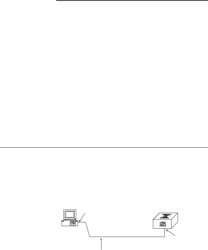
1Plug the DB-9 or DB-25 female plug of the console cable into the serial port of the PC or the terminal where the switch is to be configured.
2Connect the RJ-45 connector of the console cable to the console port of the switch, as shown in Figure 1.
Figure 1 Setting Up the Local Configuration Environment Through the Console Port
RS-232 Serial port
Console port
Console cable

Setting Terminal Parameters |
13 |
Setting Terminal |
To set terminal parameters: |
Parameters |
|
|
1 Start the PC and select Start > Programs > Accessories > Communications > |
|
HyperTerminal. The HyperTerminal window displays the Connection Description |
|
dialog box, as shown in Figure 2. |
|
Figure 2 Set Up the New Connection |
2Enter the name of the new connection in the Name field and click OK. The dialog box, shown in Figure 3 displays.
3Select the serial port to be used from the Connect using dropdown menu.
Figure 3 Properties Dialog Box
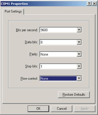
4Click OK. The Port Settings tab, shown in Figure 4, displays and you can set serial port parameters. Set the following parameters:
14 CHAPTER 1: SYSTEM ACCESS
■Baud rate = 9600
■Databit = 8
■Parity check = none
■Stopbit = 1
■Flow control = none
Figure 4 Set Communication Parameters
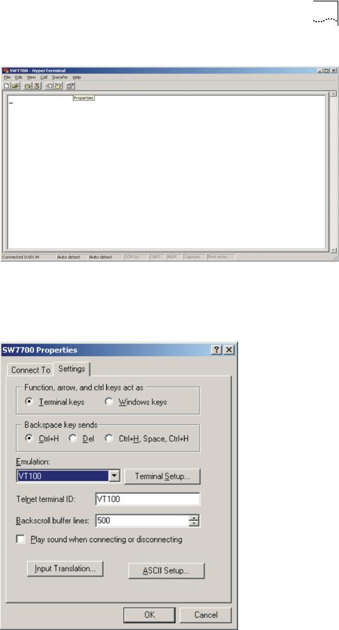
5Click OK. The HyperTerminal dialogue box displays, as shown in Figure 5.
6Select Properties.
Setting Terminal Parameters |
15 |
Figure 5 HyperTerminal Window
7In the Properties dialog box, select the Settings tab, as shown in Figure 6.
8Select VT100 in the Emulation dropdown menu.
9Click OK.
Figure 6 Settings Tab
16 CHAPTER 1: SYSTEM ACCESS
Setting the Terminal Parameters is described in the following sections:
■Configuring Through Telnet
■Configuring Through a Dial-up Modem
■Configuring the User Interface
Configuring Through Before you can telnet to a Switch 7750 and configure it, you must:
Telnet
1Configure the IP address of a VLAN interface for the Switch 7750 through the console port (using the ip address command in VLAN interface view)
2Add the port (that connects to a terminal) to this VLAN (using the port command in VLAN view)
3Log in to the Switch 7750
Tasks for Configuring through Telnet are described in the following sections:
■Connecting the PC to the Switch 7750
■Connecting Two Switch 7750 Systems
Connecting the PC to the Switch 7750
To connect the PC and Switch 7750 through Telnet:
1Authenticate the Telnet user through the console port before the user logs in by Telnet.
By default, a password is required for authenticating the Telnet user to log in the Switch 7750. If a user logs in by Telnet without a password, the user sees the message: Login password has not been set!
2 Enter system view, return to user view by pressing Ctrl+Z.
<SW7750>system-view
[SW7750]user-interface vty 0 4
[SW7750-ui-vty0]set authentication password simple/cipher xxxx
(xxxx is the preset login password of Telnet user)
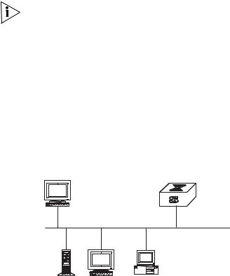
3To set up the configuration environment, connect the Ethernet port of the PC to that of the Switch 7750 through the LAN. See Figure 7.
Figure 7 Setting Up the Configuration Environment Through Telnet
Workstation
Ethernet port
Ethernet
Server Workstation |
PC (for configuring |
|
the switch through Telnet) |
Setting Terminal Parameters |
17 |
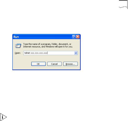
4Run Telnet on the PC by selecting Start > Run from the Windows desktop and entering Telnet in the Open field, as shown in Figure 8. Click OK.
Figure 8 Run Telnet
The terminal displays Login authentication and prompts you for the logon password.
5 Enter the password. The terminal displays the command line prompt (<SW7750>).
If the message, All user interfaces are used, please try later! appears, try to reconnect later. At most, 5 Telnet users are allowed to log on to a Switch 7750 simultaneously.
6Use the appropriate commands to configure the Switch 7750 or to monitor the operational state. Enter ? to get immediate help. For details on specific commands, refer to the chapters in this guide.
When configuring the Switch 7750 by Telnet, do not modify the IP address unless necessary, because the modification might terminate the Telnet connection. By default, after passing the password authentication and logging on, a Telnet user can access the commands at login level 0.
Connecting Two Switch 7750 Systems
Before you can telnet the Switch 7750 to another Switch 7750, as shown in Figure 9, you must:
1Configure the IP address of a VLAN interface for the Switch 7750 through the console port (using the ip address command in VLAN interface view)
2Add the port (that connects to a terminal) to this VLAN (using the port command in VLAN view)
3Log in to the Switch 7750
After you telnet to a Switch 7750, you can run the telnet command to log in and configure another Switch 7750.
18 CHAPTER 1: SYSTEM ACCESS
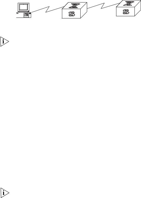
Figure 9 Provide Telnet Client Service
PC |
Telnet server |
Telnet client |
1Authenticate the Telnet user through the console port on the Telnet Server (Switch 7750) before login.
By default, a password is required for authenticating the Telnet user to log in the Switch 7750. If a user logs into Telnet without password, the system displays the following message: Login password has not been set!
2 Enter system view, return to user view by pressing Ctrl+Z.
<SW7750>system-view
[SW7750]user-interface vty 0
[SW7750-ui-vty0]set authentication password simple/cipher xxxx (xxxx
is the preset login password of Telnet user)
3Log in to the Telnet client (Switch 7750). For the login process, see “Connecting the PC to the Switch 7750”.
4Perform the following operations on the Telnet client:
<SW7750>telnet xxxx
(XXXX can be the hostname or IP address of the Telnet Server. If it is the hostname, you must use the ip host command to specify it.
5 Enter the preset login password. The Switch 7750 prompt (<SW7750>) displays. If the message, All user interfaces are used, please try later! displays, try to connect later.
6Use the appropriate commands to configure the Switch 7750 or view its operational state. Enter ? to get immediate help. For details on a specific command, refer to the appropriate chapter in this guide.
Configuring Through a To configure your router through a dial-up modem:
Dial-up Modem
1Authenticate the modem user through the console port of the Switch 7750 before the user logs in to the switch through a dial-up modem.
By default, a password is required for authenticating the modem user to log in to the Switch 7750. If a user logs in through the modem without a password, the user sees an error message.
<SW7750>system-view
[SW7750]user-interface aux 0
[SW7750-ui-aux0]set authentication password simple/cipher xxxx (xxxx
is the preset login password of the Modem user.)
2 Using the modem command, you can configure the console port to modem mode.
[SW7750-ui-aux0]modem
3To set up the remote configuration environment, connect the modems to a PC (or a terminal) serial port and to the Switch 7750 console port, as shown in Set Up Remote Configuration Environment.
Setting Terminal Parameters |
19 |
Figure 10 Set Up Remote Configuration Environment
Modem serial port line
Modem
Telephone line
PST
Modem
Console port |
Remote telephone: |
|
555-5555 |
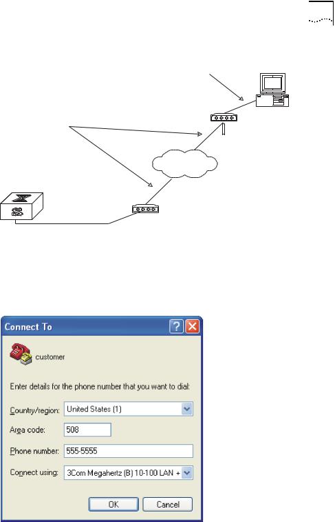
4Dial for a connection to the switch, using the terminal emulator and modem on the remote end. Dial the telephone number of the modem connected to the Switch 7750. See Figure 11 and Figure 12.
Figure 11 Set the Dialed Number
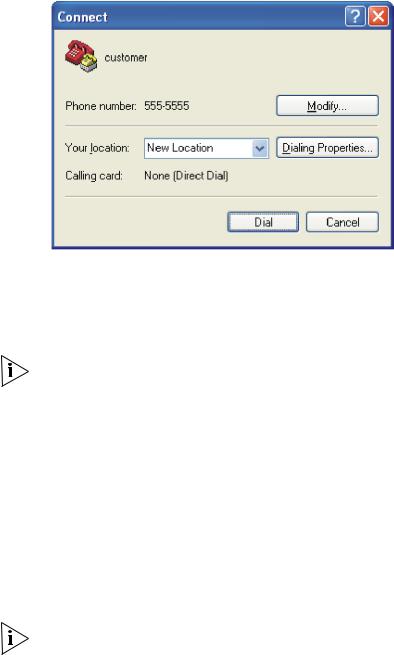
20 CHAPTER 1: SYSTEM ACCESS
Figure 12 Dial the Remote PC
5Enter the preset login password on the remote terminal emulator and wait for the
<SW7750> prompt.
6Use the appropriate commands to configure the Switch 7750 or view its operational state. Enter ? to get immediate help. For details on a specific command, refer to the appropriate chapter in this guide.
By default, after login, a modem user can access the commands at Level 0.
Configuring the User User interface configuration is another way to configure and manage port data.
Interface
The Switch 7750 supports the following configuration methods:
■Local configuration through the console port
■Remote configuration through Telnet on the Ethernet port
■Remote configuration through a modem through the console port.
There are two types of user interfaces:
■AUX user interface is used to log in the Switch 7750 through a dial-up modem. A Switch 7750 can only have one AUX port.
■VTY user interface is used to telnet the Switch 7750.
For the Switch 7750, the AUX port and Console port are the same port. There is only the type of AUX user interface.
The user interface is numbered by absolute number or relative number.
To number the user interface by absolute number:
■The AUX user interface is the first interface — user interface 0.
■The VTY is numbered after the AUX user interface. The absolute number of the first VTY is the AUX user interface number plus 1.
Setting Terminal Parameters |
21 |
To number the user interface by relative number, represented by interface + number assigned to each type of user interface:
■AUX user interface = AUX 0.
■The first VTY interface = VTY 0, the second one = VTY 1, and so on.
Tasks for configuring the user interface are described in the following sections:
■Entering the User Interface View
■Configuring the Attributes of the AUX (Console) Port
■Configuring the Terminal Attributes
■Managing Users
■Configuring the Attributes of a Modem
■Configuring Redirection
■Displaying and Debugging User Interface
Entering the User Interface View
Use the user-interface command (see Table 4) to enter a user interface view. You can enter a single user interface view or multi-user interface view to configure one or more user interfaces.
Perform the following configuration in system view.
Table 4 Enter User Interface View
Operation |
Command |
|
|
Enter a single user interface view or multi user |
user-interface [ type ] first-number [ |
interface views |
last-number ] |
|
|
Configuring the Attributes of the AUX (Console) Port
Use the speed, flow control, parity, stop bit, and data bit commands (see Table 5) to configure these attributes of the AUX (Console) port.
Perform the following configurations in user interface (AUX user interface only) view.
Table 5 Configure the Attributes of the AUX (Console) Port
Operation |
Command |
|
|
Configure the transmission speed on AUX |
speed speed-value |
(Console) port. By default, the transmission |
|
speed is 9600bps |
|
Restore the default transmission speed on |
undo speed |
AUX (Console) port |
|
Configure the flow control on AUX (Console) port. By default, no flow control is performed on the AUX (Console) port
flow-control { hardware | none | software }
Restore the default flow control mode on AUX |
undo flow-control |
(Console) port |
|
Configure parity mode on the AUX (Console) |
parity { even | mark | none | odd | space } |
port. By default, there is no parity bit on the |
|
AUX (Console) port |
|
Restore the default parity mode |
undo parity |

22 CHAPTER 1: SYSTEM ACCESS
Table 5 Configure the Attributes of the AUX (Console) Port
Operation |
Command |
|
|
Configure the stop bit of AUX (Console) port. |
stopbits { 1 | 1.5 | 2 } |
By default, AUX (Console) port supports 1 |
|
stop bit |
|
Restore the default stop bit of AUX (Console) |
undo stopbits |
port |
|
Configure the data bit of AUX (Console) port. |
databits { 7 | 8 } |
By default, AUX (Console) port supports 8 |
|
data bits. |
|
Restore the default data bit of AUX (Console) |
undo databits |
port |
|
|
|
Configuring the Terminal Attributes
The following commands can be used for configuring the terminal attributes, including enabling/disabling terminal service, disconnection upon timeout, lockable user interface, configuring terminal screen length and history command buffer size.
Perform the following configuration in user interface view. Perform the lock command in user view.
Enabling and Disabling Terminal Service After the terminal service is disabled on a user interface, you cannot log in to the Switch 7750 through the user interface. However, if a user is logged in through the user interface before disabling the terminal service, the user can continue operation. After the user logs out, the user cannot log in again. In this case, the user can log in to the Switch through the user interface only when the terminal service is enabled again. Use the commands described in Table 6 to enable or disable terminal service.
Table 6 Enabling and Disabling Terminal Service
Operation |
Command |
|
|
Enable terminal service |
shell |
Disable terminal service |
undo shell |
|
|
By default, terminal service is enabled on all the user interfaces.
Note the following points:
■For the sake of security, the undo shell command can only be used on the user interfaces other than the AUX user interface.
■You cannot use this command on the user interface through which you log in.
■You must confirm your privilege before using the undo shell command in any legal user interface.

Setting Terminal Parameters |
23 |
Configuring idle-timeout By default, idle-timeout is enabled and set to 10 minutes on all the user interfaces. The idle-timeout command is described in Table 7.
Table 7 Idle Timeout
Operation |
Command |
|
|
Configure idle-timeout |
idle-timeout minutes [ seconds ] |
|
(idle-timeout 0 means disabling |
|
idle-timeout.) |
Restore the default idle-timeout |
undo idle-timeout |
|
|
Locking the User Interface The lock command locks the current user interface and prompts the user to enter a password. This makes it impossible for others to operate in the interface after the user leaves. The lock command is described in Table 8.
Table 8 Lock User Interface
Operation |
Command |
|
|
Lock user interface |
lock |
|
|
Setting the Screen Length If a command displays more than one screen of information, you can use the screen length command to determine how many lines are displayed on a screen so that information can be separated in different screens and you can view it more conveniently. The screen-length command is described in Table 9.
Table 9 Setting Screen Length
Operation |
Command |
|
|
Set the screen length |
screen-length screen-length |
|
(screen-length 0 indicates to disable |
|
screen display separation function.) |
Restore the default screen length |
undo screen-length |
|
|
By default, the terminal screen length is 24 lines.
Setting the History Command Buffer Size
Table 10 describes the history-command max-size command. By default, the size of the history command buffer is 10.
Table 10 Set the History Command Buffer Size
Operation |
Command |
|
|
Set the history command buffer size |
history-command max-size value |
Restore the default history command buffer |
undo history-command max-size |
size |
|
|
|
Managing Users
The management of users includes: the setting of the user logon authentication method, the level of command a user can use after logging on, the level of command a user can use after logging on from the specific user interface, and the command level.

24 CHAPTER 1: SYSTEM ACCESS
Configuring the Authentication Method The authentication-mode command configures the user login authentication method that allows access to an unauthorized user. Table 11 describes the authentication-mode command.
Perform the following configuration in user interface view.
Table 11 Configure Authentication Method
Operation |
Command |
|
|
Configure the authentication method |
authentication-mode { password | |
|
scheme [ command-authorization ] |
|
} |
Configure no authentication |
authentication-mode none |
|
|
By default, terminal authentication is not required for users who log in through the console port, whereas a password is required for authenticating modem and Telnet users when they log in.
To configure authentication for modem and Telnet users:
1Configure local password authentication for the user interface.
When you set the password authentication mode, you must also configure a login password to log in successfully. Table 12 describes the set authentication password command.
Perform the following configuration in user interface view.
Table 12 Configure the Local Authentication Password
Operation |
Command |
|
|
Configure the local authentication password |
set authentication password { |
|
cipher | simple } password |
Remove the local authentication password |
undo set authentication password |
|
|
Configure for password authentication when a user logs in through a VTY 0 user interface and set the password to 3Com:
[SW7750]user-interface vty 0
[SW7750-ui-vty0]authentication-mode password
[SW7750-ui-vty0]set authentication password simple 3Com
2Configure the local or remote authentication username and password.
Use the authentication-mode scheme command to perform local or remote authentication of username and password. The type of the authentication depends on your configuration. For detailed information, see “AAA and RADIUS Operation”
Perform username and password authentication when a user logs in through the VTY 0 user interface and set the username and password to zbr and 3Com respectively:
[SW7750-ui-vty0]authentication-mode scheme
[SW7750-ui-vty0]quit
[SW7750]local-user zbr
[SW7750-luser-zbr]service-type telnet
3Authorize users to use the command lines
The authentication-mode scheme command-authorization command indicates that you must be authorized to use the command lines on the TACACS
Setting Terminal Parameters |
25 |
authentication server before executing the other commands. Commands that different users can execute are defined on the TACACS authentication server.
For example, the user tel@hwtac passes the authentication of the TACACS server 192.168.6.1 and logs into the switch through the port vty0. As the authentication-mode scheme command-authorization command is configured for the vty0 port on the switch, the NAS sends a request for authorization to the AAA server when you perform the display current-configuration command. If the reply indicates that the authorization succeeds, the user can execute the command.
4 Set the Switch 7750 to allow user access without authentication.
[SW7750-ui-vty0]authentication-mode none
By default, the password is required for authenticating the modem and Telnet users when they log in. If the password has not been set, when a user logs in, the following message displays,
If the authentication-mode none command is used, the modem and Telnet users are not required to enter a password.
Set the Command Level after Login The following command is used for setting the command level used after a user logs in.
Perform the following configuration in local-user view.
Table 13 Set Command Level Used After a User Logs In
Operation |
Command |
|
|
Set command level used after a user logging |
service-type { [ level level | |
in |
telnet [ level level ] ] | telnet |
|
[ level level | [ level level ] ] } |
Restore the default command level used after a user logging in
undo service-type { [ level | telnet [ level ] ] | telnet [ level | [ level ] ] }
By default, a Telnet user can access the commands at Level 1 after logon.
Setting the Command Level Used after a User Logs in from a User Interface
Use the user privilege level command to set the command level, after a user logs in from a specific user interface, so that a user is able to execute the commands at that command level. Table 14 describes the user privilege level command.
Perform the following configuration in user interface view.
Table 14 Set Command Level After User Login
Operation |
Command |
|
|
|
|
Set command level used after a user logging |
user |
privilege level level |
in from a user interface |
|
|
Restore the default command level used after |
undo |
user privilege level |
a user logging in from a user interface |
|
|
|
|
|

26 CHAPTER 1: SYSTEM ACCESS
By default, a user can access the commands at Level 3 after logging in through the AUX user interface, and the commands at Level 0 after logging in through the VTY user interface.
When a user logs in to the switch, the command level that the user can access depends on two points. One is the command level that the user can access, the other is the set command level of the user interface. If the two levels are different, the former is taken. For example, the command level of VTY 0 user interface is 1, however, user Tom has the right to access commands of level 3; if Tom logs in from VTY 0 user interface, he can access commands of level 3 and lower.
Setting Command Priority The command-privilege level command sets the priority of a specified command in a certain view. The command levels include visit, monitoring, configuration, and management, which are identified with command level 0 through 3, respectively. An administrator assigns authority according to user requirements. See Table 15.
Perform the following configuration in system view.
Table 15 Set Command Priority
Operation |
Command |
|
|
Set the command priority in a specified view. |
command-privilege level level view view |
|
command |
Restore the default command level in a |
undo command-privilege view view |
specified view. |
command |
|
|
Configuring the Attributes of a Modem
You can use the commands described in Table 16 to configure the attributes of a modem when logging in to the Switch through the modem.
Perform the following configuration in user interface view.
Table 16 Configure Modem
Operation |
Command |
|
|
Set the interval since the system receives the |
modem timer answer seconds |
RING until CD_UP |
|
Restore the default interval since the system |
undo modem timer answer |
receives the RING until CD_UP |
|
Configure auto answer |
modem auto-answer |
Configure manual answer |
undo modem auto-answer |
Configure to allow call-in |
modem call-in |
Configure to bar call-in |
undo modem call-in |
Configure to permit call-in and call-out. |
modem both |
Configure to disable call-in and call-out |
undo modem both |
|
|
Configuring Redirection
The send Command can be used for sending messages between user interfaces. See Table 17.

Setting Terminal Parameters |
27 |
Perform the following configuration in user view.
Table 17 Configure to Send Messages Between User Interfaces
Operation |
Command |
|
|
Configure to send messages between |
send { all | number | type number } |
different user interfaces. |
|
|
|
The auto-execute Command is used to run a command automatically after you log in. The command is automatically executed when you log in again. See Table 18.
This command is usually used to execute the telnet command automatically on a terminal, which connects the user to a designated device.
Perform the following configuration in user interface view.
Table 18 Configure Automatic Command Execution
Operation |
Command |
|
|
Configure to automatically run the command |
auto-execute command text |
Configure not to automatically run the |
undo auto-execute command |
command |
|
|
|
CAUTION: After applying the auto-execute command, the user interface can no longer be used to carry out the routine configurations for the local system.
Make sure that you will be able to log in to the system in some other way and cancel the configuration before you use the auto-execute command and save the configuration.
Telnet 10.110.100.1 after the user logs in through VTY0 automatically.:
[SW7750-ui-vty0]auto-execute command telnet 10.110.100.1
When a user logs on by VTY 0, the system will run telnet 10.110.100.1 automatically.
Displaying and Debugging User Interface
After creating the previous configuration, execute the display command in all views to display the user interface configuration, and to verify the effect of the configuration. Execute the free command in user view to clear a specified user interface.
Table 19 Display and Debug User Interface
Operation |
Command |
|
|
|
|
Clear a specified user interface |
free user-interface |
[ type ] |
|
number |
|
Display the user application information of the |
display users [ all |
] |
user interface |
|
|
Display the physical attributes and some |
display user-interface [ type |
|
configurations of the user interface |
number ] [ number ] |
[summary] |
|
|
|

28 CHAPTER 1: SYSTEM ACCESS
Command Line |
The Switch 7750 provides a series of configuration commands and command line |
Interface |
interfaces for configuring and managing the Switch 7750. The command line |
|
interface has the following features. |
|
■ Local configuration through the console port. |
|
■ Local or remote configuration through Telnet. |
|
■ Remote configuration through a dial-up Modem to log in to the Switch 7750. |
|
■ Hierarchy command protection to prevent unauthorized users from accessing |
|
the switch. |
|
■ Access to online Help by entering ?. |
|
■ Network test commands, such as Tracert and Ping, for rapid troubleshooting of |
|
the network. |
|
■ Detailed debugging information to help with network troubleshooting. |
|
■ Ability to log in and manage other Switch 7750s directly, using the telnet |
|
command. |
|
■ FTP service for the users to upload and download files. |
|
■ Ability to view previously executed commands. |
|
■ The command line interpreter that searches for a target not fully matching the |
|
keywords. You can enter the whole keyword or part of it, as long as it is unique |
|
and not ambiguous. |
Configuring a Command Line Interface is described in the following sections:
■Command Line View
■Features and Functions of the Command Line
Command Line View The Switch 7750 provides hierarchy protection for the command lines to prevent unauthorized users from accessing the switch illegally.
There are four levels of commands:
■Visit level — involves commands for network diagnosis tools (such as ping and tracert), command of the switch between different language environments of user interface (language-mode) and the telnet command. Saving the configuration file is not allowed on this level of commands.
■Monitoring level — includes the display command and the debugging command for system maintenance, service fault diagnosis, and so on. Saving the configuration file is not allowed on this level of commands.
■Configuration level — provides service configuration command, such as the routing command and commands on each network layer that are used to provide direct network service to the user.
■Management level — influences the basic operation of the system and the system support module which plays a support role for service. Commands at this level involve file system commands, FTP commands, TFTP commands, XModem downloading commands, user management commands, and level setting commands.

Command Line Interface 29
Login users are also classified into four levels that correspond to the four command levels. After users of different levels log in, they can only use commands at their own, or lower, levels.
To prevent unauthorized users from illegal intrusion, users are identified when switching from a lower level to a higher level with the super [ level ] command. User ID authentication is performed when users at a lower level switch to users at a higher level. Only when the correct password is entered three times, can the user switch to the higher level. Otherwise, the original user level remains unchanged.
Command views are implemented according to requirements that are related to one another. For example, after logging in to the Switch 7750, you enter user view, in which you can only use some basic functions, such as displaying the operating state and statistics information. In user view, key in system-view to enter system view, in which you can key in different configuration commands and enter the corresponding views.
The command line provides the following views:
■User view
■System view
■Ethernet Port view
■VLAN view
■VLAN interface view
■Local-user view
■User interface view
■FTP client view
■Cluster view
■PIM view
■RIP view
■Route policy view
■Basic ACL view
■Advanced ACL view
■Layer-2 ACL view
■RADIUS server group view
■HWTACACS view
■ISP domain view
Table 20 describes the function features of different views.

30 CHAPTER 1: SYSTEM ACCESS
For all views, use the quit command to return to system view and use the return command to return to user view.
Table 20 Function Feature of Command View
Command view |
Function |
Prompt |
Command to enter |
|
|
|
|
User view |
Show basic infor- |
<SW7750> |
Enter immediately |
|
mation about |
|
after connecting the |
|
operation and |
|
switch |
|
statistics |
|
|
System view |
Configure system |
[SW7750] |
Enter system-view |
|
parameters |
|
in user view |
Ethernet Port view |
Configure Ethernet |
[SW7750-Etherne |
100M Ethernet port |
|
port parameters |
t1/0/1] |
view |
|
|
|
Enter interface |
|
|
|
ethernet1/0/1 in |
|
|
|
system view |
|
|
[SW7750-Gigabit |
Gigabit Ethernet port |
|
|
Ethernet1/0/1] |
view |
|
|
|
Enter interface |
|
|
|
gigabitethernet |
|
|
|
1/0/1 in system view |
VLAN view |
Configure VLAN |
[SW7750- |
Enter vlan 1 in |
|
parameters |
Vlan1] |
System view |
VLAN interface view |
Configure IP interface |
[SW7750-Vlan-in |
Enter interface |
|
parameters for a |
terface1] |
vlan-interface |
|
VLAN or a VLAN |
|
1 in System view |
|
aggregation |
|
|
Local-user view |
Configure local user |
[SW7750-user- |
Enter local-user |
|
parameters |
user1] |
user1 in System view |
User interface view |
Configure user |
[SW7750-ui0] |
Enter |
|
interface parameters |
|
user-interface |
|
|
|
0 in System view |
FTP Client view |
Configure FTP Client |
[ftp] |
Enter ftp in user view |
|
parameters |
|
|
PIM view |
Configure PIM |
[SW7750-PIM] |
Enter pim in system |
|
parameters |
|
view |
RIP view |
Configure RIP |
[SW7750-rip] |
Enter rip in system |
|
parameters |
|
view |
Route policy view |
Configure route policy |
[SW7750-route- |
Enter |
|
parameters |
policy] |
route-policy |
|
|
|
policy1 permit |
|
|
|
node 10 in System |
|
|
|
view |
Basic ACL view |
Define the rule of |
[SW7750-acl- |
Enter acl number |
|
basic ACL |
basic-2000] |
2000 in System view |
Advanced ACL view |
Define the rule of |
[SW7750-acl-adv |
Enter acl number |
|
advanced ACL |
-3000] |
3000 in system view |
Layer-2 ACL view |
Define the rule of |
[SW7750-acl- |
Enter acl number |
|
layer-2 ACL |
link-4000] |
4000 in system view |
RADIUS scheme view |
Configure radius |
[SW7750-radius- |
Enter radius |
|
parameters |
1] |
scheme 1 in system |
|
|
|
view |
HWTACACS view |
Configure |
[SW7750-hwtacacs-1] |
Enter hwtacacs |
|
HWTACACS |
|
scheme1 in system |
|
parameters |
|
view |
Loading...