


2816-SFP
Table of contents
 Loading...
www.3com.com
Baseline Switch
2816-SFP/2824-SFP Plus
User Guide
3C Number: 3C16485A/3C16487
Part No. DUA1648-5AAA03
Published August 2005

3Com Corporation • 350 Campus Drive • Marlborough • MA USA 01752-3064
Copyright © 2004-2005, 3Com Corporation. All rights reserved. No part of this
documentation may be reproduced in any form or by any means or used to
make any derivative work (such as translation, transformation, or adaptation)
without written permission from 3Com Corporation.
3Com Corporation reserves the right to revise this documentation and to make
changes in content from time to time without obligation on the part of 3Com
Corporation to provide notification of such revision or change.
3Com Corporation provides this documentation without warranty, term, or
condition of any kind, either implied or expressed, including, but not limited to,
the implied warranties, terms or conditions of merchantability, satisfactory
quality, and fitness for a particular purpose. 3Com may make improvements or
changes in the product(s) and/or the program(s) described in this documentation
at any time.
If there is any software on removable media described in this documentation, it
is furnished under a license agreement included with the product as a separate
document, in the hard copy documentation, or on the removable media in a
directory file named LICENSE.TXT or !LICENSE.TXT. If you are unable to locate a
copy, please contact 3Com and a copy will be provided to you.
UNITED STATES GOVERNMENT LEGEND
If you are a United States government agency, then this documentation and the
software described herein are provided to you subject to the following:
All technical data and computer software are commercial in nature and
developed solely at private expense. Software is delivered as “Commercial
Computer Software” as defined in DFARS 252.227-7014 (June 1995) or as a
“commercial item” as defined in FAR 2.101(a) and as such is provided with only
such rights as are provided in 3Com’s standard commercial license for the
Software. Technical data is provided with limited rights only as provided in DFAR
252.227-7015 (Nov 1995) or FAR 52.227-14 (June 1987), whichever is
applicable. You agree not to remove or deface any portion of any legend
provided on any licensed program or documentation contained in, or delivered
to you in conjunction with, this User Guide.
Unless otherwise indicated, 3Com registered trademarks are registered in the
United States and may or may not be registered in other countries.
3Com and the 3Com logo are registered trademarks of 3Com Corporation.
Microsoft, MS-DOS, Windows, and Windows NT are registered trademarks of
Microsoft Corporation.
IEEE and 802 are registered trademarks of the Institute of Electrical and
Electronics Engineers, Inc.
Netscape Navigator is a registered trademark of Netscape Communications.
JavaScript is a trademark of Sun Microsystems.
All other company and product names may be trademarks of the respective
companies with which they are associated.
ENVIRONMENTAL STATEMENT
It is the policy of 3Com Corporation to be environmentally-friendly in all
operations. To uphold our policy, we are committed to:
■ Establishing environmental performance standards that comply with national
legislation and regulations.
■ Conserving energy, materials and natural resources in all operations.
■ Reducing the waste generated by all operations. Ensuring that all waste
conforms to recognized environmental standards. Maximizing the recyclable
and reusable content of all products.
■ Ensuring that all products can be recycled, reused and disposed of safely.
■ Ensuring that all products are labelled according to recognized
environmental standards.
■ Improving our environmental record on a continual basis.
End of Life Statement
3Com processes allow for the recovery, reclamation and safe disposal of all
end-of-life electronic components.
Regulated Materials Statement
3Com products do not contain any hazardous or ozone-depleting material.
Environmental Statement about the Documentation
The documentation for this product is printed on paper that comes from
sustainable, managed forests; it is fully biodegradable and recyclable, and is
completely chlorine-free. The varnish is environmentally-friendly, and the inks are
vegetable-based with a low heavy-metal content.

CONTENTS
ABOUT THIS GUIDE
Naming Convention 5
Conventions 5
Related Documentation 6
Documentation Comments 6
Product Registration 6
1 INTRODUCING THE BASELINE SWITCH
Overview of the Baseline Switch 7
Features and Capabilities 7
Autosensing of MDI/MDIX Connections 7
Autonegotiating 10/100/1000 Mbps Ports 7
SFP Ports 7
Physical Features 8
Front Panel 8
Rear Panel 11
Package Contents 11
2 INSTALLING THE SWITCH
Before You Begin 13
Positioning the Switch 13
Rack-Mounting or Free-Standing 14
Using the Mounting Kit 14
Montagesatz Anweisungen 15
Placing Units On Top of Each Other 15
Supplying Power to the Switch 16
Checking for Correct Operation 16
Connecting a Network Device 17
Using SFP Transceivers 18
Approved SFP Transceivers 18
Inserting an SFP Transceiver 18
Removing an SFP Transceiver 19
Performing Spot Checks 19
3 CONNECTING TO THE WEB INTERFACE
Requirements for Accessing the Web Interface 21
Running the Discovery Application 21
Logging On to the Web Interface 22
Navigating Around the Web Interface 23
Menu 23
Buttons 24
Device Mimic 24
Accessing the Interface Without Using Discovery 25
DHCP Assigned IP Address 25
Manually Assigned (Static) IP Address 25
4 CONFIGURING THE SWITCH
Configuration Overview 27
Viewing Switch Information 27

Changing the Admin Password 28
Modifying the IP Address Settings 29
Automatic IP Configuration 29
Setting the IP Address 30
Configuring Port Settings 31
Basic Port Configuration 31
Advanced Port Configuration 33
Configuring VLANs 33
Creating a VLAN 34
Sample VLAN Configurations 35
Removing a VLAN 37
Configuring Link Aggregation 37
Guidelines for Creating Aggregated Links 38
Defining the Members of an Aggregated Link 38
Modifying Settings and Deleting an Aggregated
Link 39
Viewing the Trunk Summary 39
Viewing Statistics 40
Mirroring Port Traffic 41
Running Cable Diagnostic 42
Using the System Tools 42
Restart 42
Configuration 43
Resetting to Factory Defaults 43
Backing Up and Restoring Configuration 44
Upgrade 44
Spanning Tree 45
802.1p Prioritization 46
Viewing Support Information 47
5 TROUBLESHOOTING
Forgotten Password 49
Forgotten Static IP Address 49
Solving LED Issues 49
If the Problem Persists 52
A OBTAINING SUPPORT FOR YOUR PRODUCT
Register Your Product 53
Purchase Value-Added Services 53
Troubleshoot Online 53
Access Software Downloads 53
Telephone Technical Support and Repair 54
Contact Us 54
B TECHNICAL INFORMATION
Related Standards 57
Environmental 57
Physical 57
Electrical 57
C SAFETY INFORMATION
Important Safety Information 59
L'Information De Sécurité Importante 60
Wichtige Sicherheitinformationen 61
GLOSSARY
REGULATORY NOTICES
INDEX
ABOUT THIS GUIDE
This guide is intended for use by those responsible for
installing and setting up network equipment.
Consequently, it assumes a basic working knowledge of
local area networks (LANs).
If a release note is shipped with this 3Com Baseline
Switch 2816-SFP/2824-SFP Plus and contains
information that differs from the information in this
guide, follow the information in the release note.
Most user guides and release notes are available in
Adobe Acrobat Reader Portable Document Format (PDF)
on the 3Com World Wide Web site:
www.3com.com
Conventions
Table 1 and Table 2 list conventions that are used
throughout this guide.
Tabl e 1 Notice Icons
Icon Notice Type Description
Information note Information that describes important
Caution Information that alerts you to poten-
Warning Information that alerts you to poten-
features or instructions
tial loss of data or potential damage
to an application, system, or device
tial personal injury
Naming Convention
Throughout this guide, the 3Com Baseline Switch
2816/2824-SFP Plus is referred to as the Switch.
Category 3 and Category 5 Twisted Pair Cables are
referred to as Twisted Pair Cables throughout this guide.
Tabl e 2 Text Conventions
Convention Description
The words “enter”
and “type”
Keyboard key names If you must press two or more keys simulta-
When you see the word “enter” in this guide,
you must type something, and then press Return
or Enter. Do not press Return or Enter when an
instruction simply says “type.”
neously, the key names are linked with a plus
sign (+). Example:
Press Ctrl+Alt+Del
6 ABOUT THIS GUIDE
Tab l e 2 Text Conventions (continued)
Convention Description
Words in italics Italics are used to:
■ Emphasize a point.
■ Denote a new term at the place where it is
defined in the text.
■ Identify menu names, menu commands, and
software button names. Examples:
From the Help menu, select Contents.
Click OK.
Related Documentation
In addition to this guide, each 3Com Baseline Switch
2816-SFP/2824-SFP Plus documentation set includes the
following:
■ Online Help – Accessible from the Web interface,
provides information that helps you perform tasks
using the Web interface.
■ Release Notes – Provide information about the
current software release, including new features,
modifications, and known problems.
Documentation Comments
Your suggestions are very important to us. They will
help make our documentation more useful to you.
Please e-mail comments about this document to 3Com
at:
pddtechpubs_comments@3com.com
Please include the following information when commenting:
■ Document title
■ Document part number (on the title page)
■ Page number (if appropriate)
Example:
■ 3Com Baseline Switch 2816-SFP/2824-SFP Plus User
Guide
■ Part Number DUA1648-5AAA03
■ Page 24
Do not use this e-mail address for technical support
questions. For information about contacting Technical
Support, please refer to “Viewing Support Information”
on page 47.
The Switch is part of the extensive Baseline range of
3Com products. This range includes hubs, switches,
power systems and other networking equipment, and is
continually being developed. Contact your supplier for
the latest product information and to order these products.
Product Registration
You can now register your Baseline Switch on the 3Com
Web site to receive up-to-date information on your
product:

1
INTRODUCING THE BASELINE SWITCH
This chapter provides an overview of the features and
capabilities of the 3Com
2816/2824-SFP Plus. It also identifies the contents of the
Switch package and helps you get to know the physical
features of the device.
®
Baseline Switch
Overview of the Baseline Switch
The 3Com Baseline Switch 2816-SFP/2824-SFP Plus is a
versatile, easy-to-use configurable Switch. It is ideal for
users who want the high-speed performance of
10/100/1000 switching with the added functionality of
Gigabit links, but do not need sophisticated
management capabilities. The Switch is shipped ready
for use. No configuration is necessary.
Features and Capabilities
The Switch has 16 (2816-SFP) or 24 (2824-SFP) shielded
RJ-45, 10/100/1000 Mbps auto-negotiating ports and
four Small Form Factor Pluggable (SFP) transceiver slots
on the front panel for easy, flexible connection to
fiber-based Gigabit media.
Autosensing of MDI/MDIX Connections
All ports on the Switch can autosense both medium
dependent interface (MDI) and medium dependent
interface crossover (MDIX) connections. This allows you
to connect network devices to each port using either a
normal straight-through TP (twisted pair) cable or a
‘crossover’ TP cable.
Any port can therefore be used to connect to another
switch port, server, or workstation without additional
configuration.
Autonegotiating 10/100/1000 Mbps Ports
Each 10/100/1000 Mbps port automatically determines
the speed and duplex mode of the connected
equipment and provides a suitable switched connection.
The 1000BASE-T ports also support automatic
10/100/1000 Mbps speed detection.
10/100 Mbps connections on these 1000BASE-T ports
can operate in either half-duplex or full-duplex mode.
1000 Mbps connections, on the other hand, only
operate in full duplex mode.
SFP Ports
The four SFP ports support fiber Gigabit Ethernet
short-wave (SX) and long-wave (LX) SFP transceivers in
8 CHAPTER 1: INTRODUCING THE BASELINE SWITCH
any combination. This offers you the flexibility of using
SFP transceivers to provide connectivity between the
Switch and a 1000 Mbps core network.
When an SFP port is in operation, the corresponding
10/100/1000BASE-T port is disabled.
Physical Features
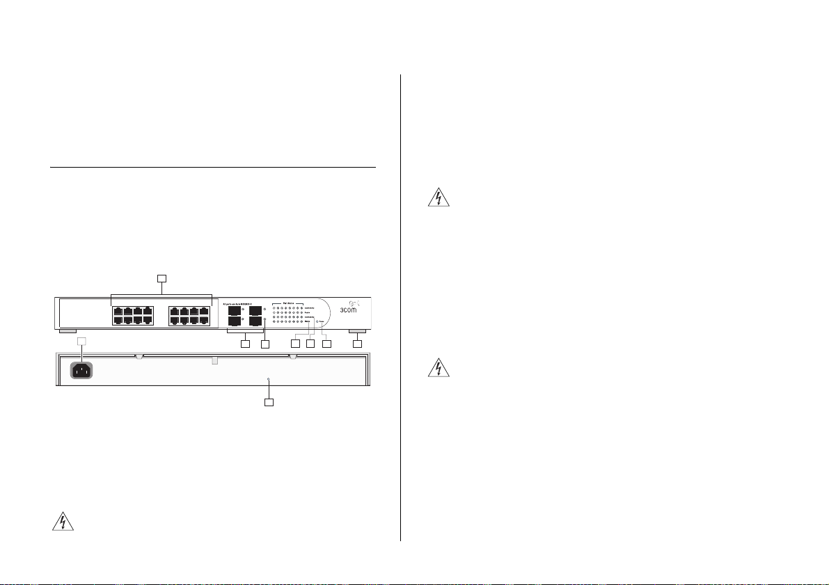
Figure 1 shows the front and rear panels of the Switch.
The numbers in this diagram refer to numbered sections
in “Front Panel” below and “Rear Panel” on page 11.
Figure 1 Front and Rear Panels (2816-SFP)
1
BaselineSwitch 2816-SFP Plus
1
9
8
5
4
13
12
8
16
Front Panel
The front panel of the Switch contains a series of
indicator lights (LEDs) that help describe the state of
various networking and connection operations.
(1) RJ-45 10/100/1000 Ports
WARNING: RJ-45 Ports. These are shielded RJ-45 data
sockets. They cannot be used as standard traditional
Module Present
Link/Activity : Green = 1000M, Yellow = 10/1000M,
Flash = Activity, Duplex : On = Full, Off = Half
5
4
2
9
telephone sockets, or to connect the unit to a
traditional PBX or public telephone network. Only
connect RJ-45 data connectors, network telephony
systems, or network telephones to these sockets.
Either shielded or unshielded data cables with shielded
or unshielded jacks can be connected to these data
sockets.
AVERTISSEMENT: Points d’accès RJ-45. Ceux-ci sont
protégés par des prises de données. Ils ne peuvent pas
être utilisés comme prises de téléphone conventionnelles
standard, ni pour la connection de l’unité à un réseau
téléphonique central privé ou public. Raccorder
seulement connecteurs de données RJ-45, systèmes de
réseaux de téléphonie ou téléphones de réseaux à ces
prises.
Il est possible de raccorder des câbles protégés ou non
3C16485A
3
6
7
protégés avec des jacks protégés ou non protégés à ces
prises de données.
WARNHINWEIS: RJ-45-Porte. Diese Porte sind
geschützte Datensteckdosen. Sie dürfen weder wie
normale traditionelle Telefonsteckdosen noch für die
Verbindung der Einheit mit einem traditionellem
privatem oder öffentlichem Telefonnetzwerk gebraucht
werden. Nur RJ-45-Datenanscluße, Telefonnetzsysteme
or Netztelefone an diese Steckdosen anschließen.
Entweder geschützte oder ungeschützte Buchsen dürfen
an diese Datensteckdosen angeschlossen werden.
The Switch has 16 (2816-SFP) or 24 (2824-SFP)
10/100/1000 Mbps auto-negotiating ports. Each port

Physical Features 9
supports automatic MDI/MDI-X detection and can be
connected to a 10BASE-T, 100BASE-TX, or a
1000BASE-T device.
Ports 1 to 16 (2816-SFP) or ports 1 to 24 (2824-SFP) are
auto-negotiating: their speed and duplex mode (half
duplex or full duplex for 10BASE-T and 100BASE-TX, full
duplex only for 1000BASE-T) are automatically
determined by the capabilities of the connected device.
CAUTION: The Switch supports full duplex
auto-negotiation. If auto-negotiation is disabled for
1000BASE-T, then the Switch uses the forced-mode
default of 100 full duplex mode. If the connected device
does not support auto-negotiation, the Switch will
operate in half duplex mode (even if the attached device
is operating in full duplex mode). In such a
configuration, you may notice some degradation of
network performance. 3Com recommends that you use
devices that are capable of auto-negotiation (and that
you ensure that auto-negotiation is enabled, if it is a
configurable option).
(2) SFP Ports
The Small Form Factor Pluggable (SFP) ports are
numbered 13 to 16. If an SFP transceiver (purchased
separately) is installed in a slot and is active, the
associated RJ-45 port of the same number is disabled.
SFP transceivers to provide connectivity between the
Switch and remote 1000 Mbps workgroups or to create
a high-capacity aggregated link backbone connection.
SFP ports are numbered 13 to 16 (2816-SFP) and 21 to
24 (2824-SFP) on the Switch. When an SFP port is
active, it has priority over the 10/100/1000 port of the
same number. The corresponding 10/100/1000 port is
disabled when an SFP transceiver is plugged in.
(3) Link/Activity Status LEDs
The following table lists LEDs visible on the front of the
Switch, and how to read their status according to color.
Tabl e 1 10BASE-T/100BASE-TX Ports
Status Meaning
Green The link is operating at 1000 Mbps.
Yellow The link is operating at 10 or 100 Mbps.
Flashing
Green
Flashing
Yellow
Packets are being received or transmitted on the
port at 1000 Mbps.
Packets are being received or transmitted on the
port at 10 or 100 Mbps.
The four SFP ports support fiber Gigabit Ethernet
short-wave (SX) and long-wave (LX) SFP transceivers in
any combination. This offers you the flexibility of using

10 CHAPTER 1: INTRODUCING THE BASELINE SWITCH
Tab l e 1 10BASE-T/100BASE-TX Ports
Flashing
Yellow to
Green
Off The link has not been established, either nothing is
Port disabled or link loopback error.
connected to the port, or there is a problem:
■ Check that the attached device is powered on.
■ Check that the cable or fiber is the correct type
and is not faulty.
■ For fiber connections, ensure that the receive
(RX) and transmit (TX) cable connectors are not
swapped.
If these checks do not identify the cause of the
problem, it may be that the unit or the device connected to the port is faulty. Contact your supplier
for further advice.
(4) Module Active LEDs
The Module Active LEDs shows the status of any SFP
modules that are installed.
Tab l e 2 Module Active LEDs
Status Meaning
Green Fiber SFP is inserted in the slot.
Off No fiber SFP is inserted in the slot.
(5) Port Duplex LEDs
The second and fourth (bottom) row of Status LEDs,
which are colored yellow, show the duplex status of the
related ports.
Tabl e 3 Duplex LEDs
Status Meaning
Off No link, not yet negotiated or the port is operating
in half-duplex mode.
Yellow The port is operating in full-duplex mode.
(6) Power LED
The Power LED shows the power status of the Switch:
Tabl e 4 Power LEDs
Status Meaning
Green The unit is powered on and ready for use.
Off ■ The unit is not receiving power:
Flashing
Green
Yell ow ■ Power-on self test or loopback test failed.
■ Check that the power cord is connected cor-
rectly.
■ If the unit still does not operate, contact your
supplier.
■ Power-on self test is in progress.
Switch is in failsafe mode.

(7) Self-Adhesive Pads
The unit is supplied with four self-adhesive rubber pads.
If you intend to rack-mount the Switch, do not apply
the pads.
If the unit is to be part of a free-standing stack, apply
the pads to each marked corner area on the underside
of the unit. Place the unit on top of the lower unit,
ensuring that the pads locate with the recesses of the
lower unit.
Rear Panel
(8) Power Supply
The Switch automatically adjusts to the supply voltage.
Only use the power cord that is supplied with the unit.
(9) Recovery button
The recovery button reinitializes the Switch. This returns
the Switch to the factory default settings if, for
example, you have forgotten the default IP address, or
forgotten your user name or password.
CAUTION: 3Com recommends that you back up your
configuration settings before you recover the Switch,
otherwise your configuration will be lost. Refer to
“Configuration” on page 43 for details.
Package Contents 11
Package Contents
Before installing and using the Switch, verify that your
Switch package is complete. The Switch comes with:
■ One power cord
■ Four standard height, self-adhesive rubber pads
■ One mounting kit
■ 3Com Installation CD
■ This User Guide
■ Warranty flyer
If any of the above items are damaged or missing,
contact your 3Com network supplier immediately.

12 CHAPTER 1: INTRODUCING THE BASELINE SWITCH

2
INSTALLING THE SWITCH
This chapter contains information that you need to
install and set up the Switch. It covers the following
topics:
■ Before You Begin
■ Positioning the Switch
■ Rack-Mounting or Free-Standing
■ Supplying Power to the Switch
■ Connecting a Network Device
■ Using SFP Transceivers
■ Performing Spot Checks
Before You Begin
WARNING: Safety Information. Before installing or
removing any components from the Switch or carrying
out any maintenance procedures, read the safety
information provided in Appendix C of this guide.
AVERTISSEMENT: Consignes de Sécurité. Avant
d'installer ou d'enlever tout composant du Switch ou
d'entamer une procédure de maintenance, lisez les
informations relatives à la sécurité qui se trouvent dans
l'Appendice B (Appendix C) de ce guide.
WARNHINWEIS: Sicherheitsinformationen. Bevor Sie
Komponenten aus dem Switch entfernen oder dem
Switch hinzufuegen oder Instandhaltungsarbeiten
verrichten, lesen Sie die Sicherheitsanweisungen, die in
Anhang B (Appendix C) in diesem Handbuch
aufgefuehrt sind.
ADVERTENCIA: Información de Seguridad. Antes de
instalar o extraer cualquier componente del product o
de realizar tareas de mantenimiento, debe leer la
información de seguridad facilitada en el Apéndice B
(Appendix C) de esta guía del usuario.
AVVERTENZA: Informazioni di Sicurezza. Prima di
installare o rimuovere qualsiasi componente dal product
o di eseguire qualsiasi procedura di manutenzione,
leggere le informazioni di sicurezza riportate
nell'Appendice B (Appendix C) della presente guida per
l'utente.
Positioning the Switch
The Switch is suitable for use in an office environment
where it can be free-standing or mounted in a standard
19-inch equipment rack.

14 CHAPTER 2: INSTALLING THE SWITCH
Alternatively, the Switch can be rack-mounted in a
wiring closet or equipment room. A mounting kit,
containing two mounting brackets and four screws, is
supplied with the Switch.
When deciding where to position the Switch, ensure
that:
■ It is accessible and cables can be connected easily.
■ Cabling is away from sources of electrical noise.
These include lift shafts, microwave ovens, and air
conditioning units. Electromagnetic fields can
interfere with the signals on copper cabling and
introduce errors, therefore slowing down your
network.
■ Water or moisture cannot enter the case of the unit.
■ Air flow around the unit and through the vents in
the side of the case is not restricted (3Com
recommends that you provide a minimum of 25 mm
(1 in.) clearance).
■ The air is as free of dust as possible.
■ Temperature operating limits are not likely to be
exceeded. It is recommended that the unit is
installed in a clean, air conditioned environment.
It is always good practice to wear an anti-static wrist
strap when installing network equipment, connected to
a ground point. If one is not available, try to keep in
contact with a grounded rack and avoid touching the
unit's ports and connectors, if possible. Static discharge
can cause reliability problems in your equipment.
Rack-Mounting or Free-Standing
The unit can be mounted in a 19-inch equipment rack
using the mounting kit or it can be free-standing. Do
not place objects on top of the unit or stack.
CAUTION: If installing the Switch in a free-standing
stack of different size Baseline or Superstack
the smaller units must be installed above the larger
ones. Do not have a free-standing stack of more than
six units.
Using the Mounting Kit
The Switch is supplied with two mounting brackets and
four screws. These are used for rack mounting the unit.
When mounting the unit, you should take note of the
guidelines given in “Positioning the Switch” on
page 13.
The Switch is 1U high and will fit in a standard 19-inch
rack.
CAUTION: Before continuing, disconnect all cables from
the unit. Remove the self-adhesive pads from the
underside of unit, if already fitted.
To rack-mount the Switch:
1 Place the unit the right way up on a hard, flat surface
with the front facing towards you.
2 Locate a mounting bracket over the mounting holes on
one side of the unit.
®
3 units,
Rack-Mounting or Free-Standing 15
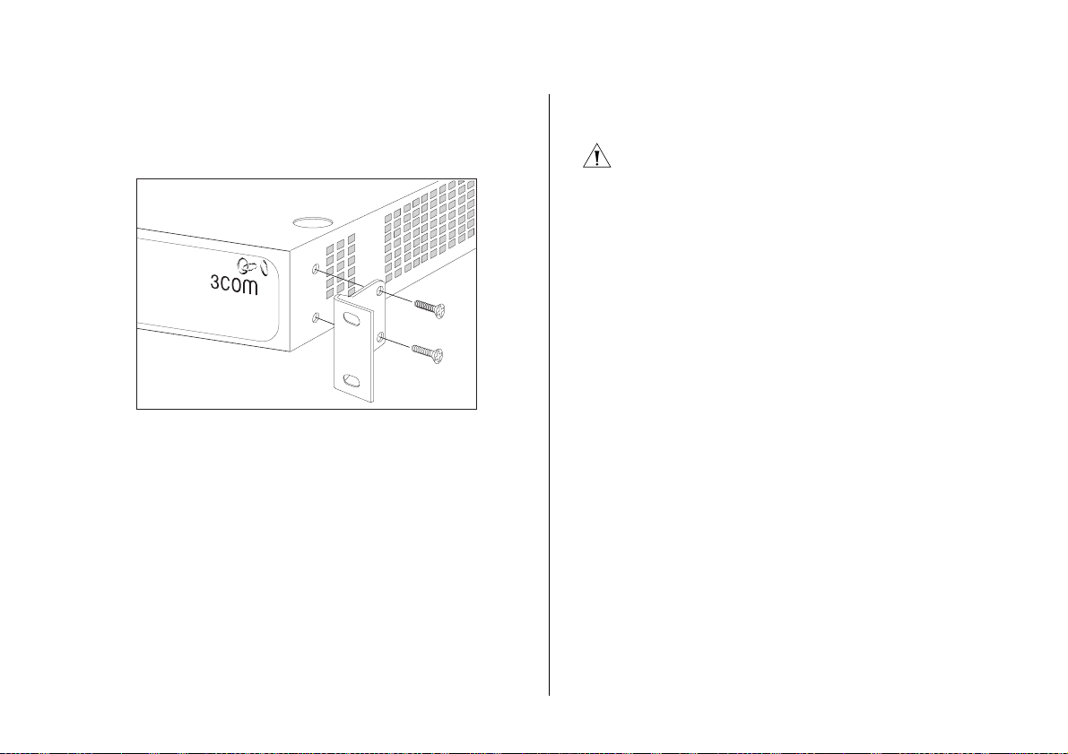
3 Insert the two screws supplied in the mounting kit, and
the fully tighten with a suitable screwdriver.
Figure 2 Inserting the Screws
Baseline Switch 2816-SFP Plus
4 Repeat the two previous steps for the other side of the
unit.
5 Insert the unit into the 19-inch rack and secure with
suitable screws (not provided).
6 Reconnect the cables.
Montagesatz Anweisungen
Der Switch wird mit zwei Halterungen und vier
Schrauben geliefert. Diese werde für den Einbau in
einen Baugruppenträger benutzt. Bei der Montage der
Baugruppe beachten Sie die Anweisungen aus
“Positioning the Switch” on page 13.
Der Switch ist eine Baueinheit hoch und passt in einen
Standard 19'' (Zoll) Baugruppenträger.
ACHTUNG: Entfernen Sie alle Kabel, bevor Sie
fortfahren. Entfernen Sie die selbstklebenden Polster
(Füße) von der Unterseite der Baugruppe, falls diese
bereits angebracht sind.
1 Plazieren Sie die Baugruppe aufrecht auf einer harten,
ebenen Fläche mit der Vorderseite zu Ihnen.
2 Ordnen Sie eine der Halterungen über den Löchern an
der Seite der Baugruppe an.
3 Stecken Sie zwei der mitgelieferten Schrauben in die
Löcher und drehen Sie diese mit einem geeigneten
Schraubendreher fest.
4 Widerholen Sie letzten beiden Schritte auf der anderen
Seite der Baugruppe.
5 Führen Sie die Baugruppe in den 19" (Zoll)
Baugruppenträger ein und sichern sie die Baugruppe mit
geeigneten Schrauben. (Nicht im Lieferumfang
enthalten.)
6 Schließen Sie alle Kabel wieder an.
Placing Units On Top of Each Other
If the Switch units are free-standing, up to four units
can be placed one on top of the other. If you are mixing
a variety of Baseline and SuperStack units, the smaller
units must be positioned at the top.
If you are placing Switch units one on top of the other,
you must use the self-adhesive rubber pads supplied.

16 CHAPTER 2: INSTALLING THE SWITCH
Apply the pads to the underside of each Switch, sticking
one in the marked area at each corner.
Place the Switch units on top of each other, ensuring
that the pads of the upper unit line up with the recesses
of the lower unit.
Supplying Power to the Switch
Power problems can be the cause of serious failures and
downtime in your network. Ensure that the power input
to your system is clean and free from sags and surges to
avoid unforeseen network outages. We recommend that
you install power conditioning, especially in areas prone
to black outs, power dips and electrical storms.
The unit is intended to be grounded. Ensure it is
connected to earth ground during normal use. Installing
proper grounding helps to avoid damage from lightning
and power surges.
Before powering on the Switch, verify that the network
cables and the power cable are securely connected.
CAUTION: The Switch has no ON/OFF switch. The only
way to power on and power off the Switch is by
connecting and disconnecting the power cord. This is
called “power cycling”.
To power on the Switch:
1 Plug the power cord into the power socket on the rear
panel of the Switch. Refer to “(8) Power Supply” on
page 11 for more information.
2 Plug the other end of the power cord into a power
outlet.
When the Switch is powered on, the Power LED lights
up. If the Power LED does not light up, refer to “(6)
Power LED” on page 10 for more information.
Checking for Correct Operation
After you power on the Switch, it automatically
performs a power-on self-test (POST). During POST, the
Power LED on the front panel of the Switch flashes
green.
When POST is complete, the Power LED turns green. If
the Power LED turns yellow after POST, it means that
POST failed and the Switch has entered fail-safe mode.
Table 5Table 5 summarizes the possible colors for the
Power LED after POST.
Tabl e 5 Possible Power LED Colors After POST
Color State
Green The unit is powered on and ready for use
Connecting a Network Device 17
Color State
Yellow Power-on self-test or loopback test failed. The
Switch is in fail-safe mode. This can happen if a
ports or ports fail when the Switch was powered
on.
Off The unit is not receiving power:
■ Verify that the power cord is connected cor-
rectly, and then try powering on the Switch
again
■ If the Switch still does not operate, contact
your 3Com network supplier
If POST fails, try the following:
■ Power off the Switch, and then power it on again.
Check the Power LED and see if POST was
successfully completed.
■ Reset the Switch. See “Resetting to Factory Defaults”
on page 43.
CAUTION: Resetting the Switch to its factory defaults
erases all your settings. You will need to reconfigure the
Switch after you reset it.
If these do not resolve the issue:
■ Check the 3Com Knowledgebase for a solution. To
visit the 3Com Knowledgebase Web site, start your
Web browser, and then enter
http://knowledgebase.3com.com.
■ Contact your 3Com network supplier for assistance.
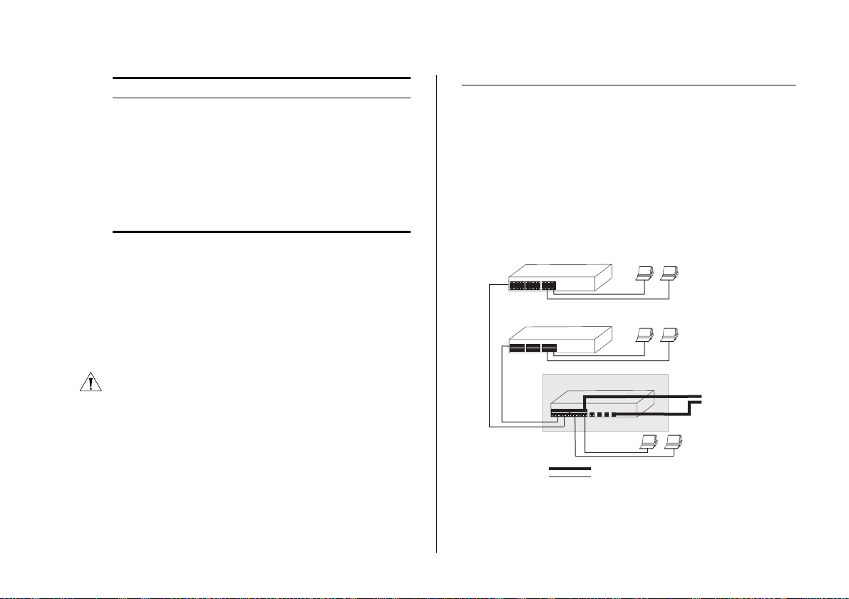
Connecting a Network Device
To connect a network device to the Switch, use
Category 5 unshielded or shielded (screened) 100 Ohm
TP cables (or Category 3 cables for 10 Mbps
connections).
For optimal connections, ensure that the cable length
for each connection is not longer than 100 m (328 ft).
Figure 3 Connecting Devices to the Switch
Baseline 10/100 Switch
Baseline 10/100 Switch
Baseline Switch 2250Baseline Switch 2816/2824-SFP Plus
1000 Mbps link
10 Mbps or 100 Mbps link
To connect a device to the Switch:
1 Connect one end of the cable to an RJ-45 port on the
Switch.
Endstations on switched
100 Mbps connections
Endstations on switched
100 Mbps connections
1000 Mbps copper or F iber
connection to backbone
or server/worksation
Endstations on
switched 100 Mbps or 1000 Mbps
connections

18 CHAPTER 2: INSTALLING THE SWITCH
2 Connect the other end to the appropriate RJ-45 port on
the connecting device.
For 1000BASE-T operation, 3Com recommends using
Category 5e or 6 cables.
Using SFP Transceivers
The following sections describe how to insert and
remove an SFP transceiver from an SFP slot.
SFP transceivers are hot-insertable and hot-swappable.
You can remove them from and insert them into any
SFP port without having to power off the Switch.
Approved SFP Transceivers
The following list of approved SFP transceivers is correct
at the time of publication:
■ 3CSFP91 SFP (SX)
■ 3CSFP92 SFP (LX)
To access the latest list of approved SFP transceivers for
the Switch on the 3Com Corporation World Wide Web
site, enter this URL into your Internet browser:
www.3com.com
3Com recommends using 3Com SFPs on the Switch. If
you insert an SFP transceiver that is not supported, the
Switch will not recognize it.
Inserting an SFP Transceiver
To be recognized as valid, the SFP transceiver must be
one of the following:
■ 1000BASE-SX SFP transceiver – Use this transceiver
to connect the Switch directly to a multimedia
fiber-optic cable.
■ 1000BASE-LX SFP transceiver – Use this transceiver
to connect the Switch directly to a single-mode
fiber-optic cable or to multimode fiber using a
conditioned launch cable.
If the SFP transceiver is faulty, it will not operate within
the Switch. See “Troubleshooting” starting on page 49.
To insert an SFP transceiver:
1 Hold the transceiver so that the fiber connector is
toward you and the product label is visible, as shown in
Figure 4. Ensure the wire release lever is closed (in the
upright position).
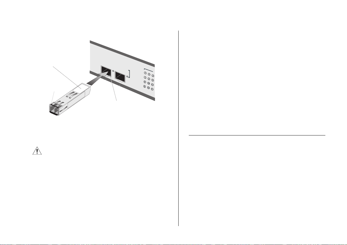
Performing Spot Checks 19
Figure 4 Inserting an SFP Transceiver
Product
label
Wire release
lever
Module Present
Suitable slot
n host Switcho
Link/Activity :
Flash = Act
2 Gently slide the transceiver into the SFP slot until it
clicks into place.
CAUTION: SFP transceivers are keyed and can be properly
inserted only one way. If the transceiver does not click
when you insert it, remove it, turn it over, and then re-insert it.
3 Remove the plastic protective cover, if fitted.
4 Connect the fiber cable.
5 The transceiver connects to the network using a duplex
LC connector. Attach a male duplex LC connector on
the network cable into the duplex LC connector on the
transceiver.
6 Connect the other end of the cable to a device fitted
with an appropriate Gigabit Ethernet connection.
7 Check the Module Active LEDs on the front of the
Switch to ensure that it is operating correctly.
Removing an SFP Transceiver
Removing an SFP transceiver does not require powering
off the Switch.
To remove an SFP transceiver:
1 Disconnect the cable from the transceiver.
2 Move the wire release lever downwards until it is
pointing toward you.
3 Pull the wire release lever toward you to release the
catch mechanism.
The SFP transceiver should slide out easily.
Performing Spot Checks
At frequent intervals, you should visually check the
Switch. Regular checks can give you an early warning of
a possible failure; any problems can then be attended to
when there will be least effect on users.
3Com recommends periodically checking the items listed
in Table 6.

20 CHAPTER 2: INSTALLING THE SWITCH
Tab l e 6 Items to Check
Item Verify That
Cabling All external cabling connections are secure and
Cooling Fan Where possible, check that the cooling fan is
that no cables are pulled taut
operating by listening to the unit. The fan is fitted on the right side of the unit (when viewed
from the front).
If you experience any problems operating the Switch,
refer to “Troubleshooting” on page 49.

3
The Switch has a built-in Web interface that you can
use to set the admin password, change the IP address
that is assigned to the Switch, and configure its
advanced settings.
If you only want the Switch to function as a basic layer
2 switch, you do not need to access the Web interface
and configure the Switch.
This chapter provides information on how the gain
access to the Web interface using the Discovery
application. It also introduces the menu items and
buttons that are available on the Web interface.
CONNECTING TO THE WEB INTERFACE
Requirements for Accessing the Web Interface
To connect to the Web interface, you need the
following:
■ The Discovery application, which is included on
3Com Baseline Switch 2816-SFP/2824-SFP Plus
CD-ROM that is supplied with your Switch
■ A computer that is connected to the Switch and that
has a Web browser
The following topics are covered:
■ Requirements for Accessing the Web Interface
■ Running the Discovery Application
■ Logging On to the Web Interface
■ Navigating Around the Web Interface
■ Accessing the Interface Without Using Discovery
Running the Discovery Application
The 3Com Baseline Switch 2816-SFP/2824-SFP Plus
CD-ROM contains, among others, the Discovery
application.
To use Discovery to connect to the Web interface, do
the following:
1 On a computer that is connected to the Switch, insert
the CD-ROM into its CD drive.
Discovery should start automatically. If it does not start
automatically, go to the
CD-ROM, and then double-click
\Discovery folder on the
discovery.exe.
22 CHAPTER 3: CONNECTING TO THE WEB INTERFACE
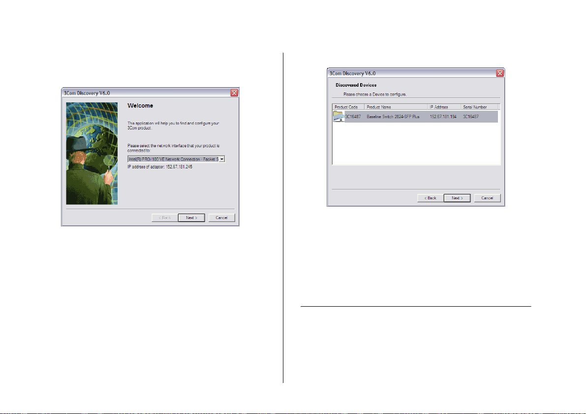
The Welcome screen of Discovery appears.
Figure 5 Welcome Screen of Discovery
2 If the computer has multiple network adapters, select
the adapter that connects the computer to the Switch,
and then click Next.
If the computer has only one adapter, click Next.
Discovery searches the network for 3Com devices.
When detection is complete, the Discovered Devices
screen displays detected network devices.
Figure 6 Discovered Devices Screen
3 On the Discovered Devices screen, click Baseline Switch
2816-SFP/2824-SFP Plus, and then click Next.
The Completing the 3Com Discovery Application screen
appears.
4 Click Finish.
The Web interface loads in your Web browser.
Logging On to the Web Interface
After the Web interface loads in your Web browser, the
first page that appears is the logon page. On this page,
you need to enter the administration user name and
password to gain access to the Web interface.
Loading...