


 Loading...
Router 3000 Family
Installation Guide
Router 3012 (3C13612)
Router 3013 (3C13613)
Router 3015 (3C13615)
Router 3016 (3C13616)
Router 3018 (3C13618)
http://www.3com.com/
Part No. 10014206
Published March 2004
3Com Corporation |
Copyright © 2004, 3Com Corporation. All rights reserved. No part of this documentation may be reproduced |
350 Campus Drive |
in any form or by any means or used to make any derivative work (such as translation, transformation, or |
Marlborough, MA |
adaptation) without written permission from 3Com Corporation. |
01752-3064 |
3Com Corporation reserves the right to revise this documentation and to make changes in content from time |
|
|
|
to time without obligation on the part of 3Com Corporation to provide notification of such revision or change. |
|
3Com Corporation provides this documentation without warranty, term, or condition of any kind, either |
|
implied or expressed, including, but not limited to, the implied warranties, terms or conditions of |
|
merchantability, satisfactory quality, and fitness for a particular purpose. 3Com may make improvements or |
|
changes in the product(s) and/or the program(s) described in this documentation at any time. |
|
If there is any software on removable media described in this documentation, it is furnished under a license |
|
agreement included with the product as a separate document, in the hard copy documentation, or on the |
|
removable media in a directory file named LICENSE.TXT or !LICENSE.TXT. If you are unable to locate a copy, |
|
please contact 3Com and a copy will be provided to you. |
|
UNITED STATES GOVERNMENT LEGEND |
|
If you are a United States government agency, then this documentation and the software described herein |
|
are provided to you subject to the following: |
|
All technical data and computer software are commercial in nature and developed solely at private expense. |
|
Software is delivered as “Commercial Computer Software” as defined in DFARS 252.227-7014 (June 1995) |
|
or as a “commercial item” as defined in FAR 2.101(a) and as such is provided with only such rights as are |
|
provided in 3Com’s standard commercial license for the Software. Technical data is provided with limited |
|
rights only as provided in DFAR 252.227-7015 (Nov 1995) or FAR 52.227-14 (June 1987), whichever is |
|
applicable. You agree not to remove or deface any portion of any legend provided on any licensed program |
|
or documentation contained in, or delivered to you in conjunction with, this User Guide. |
|
Unless otherwise indicated, 3Com registered trademarks are registered in the United States and may or may |
|
not be registered in other countries. |
|
3Com and the 3Com logo are registered trademarks of 3Com Corporation. |
|
Intel and Pentium are registered trademarks of Intel Corporation. Microsoft, MS-DOS, Windows, and |
|
Windows NT are registered trademarks of Microsoft Corporation. |
|
All other company and product names may be trademarks of the respective companies with which they are |
|
associated. |

CONTENTS
ABOUT THIS GUIDE
Conventions 5
INTRODUCING THE ROUTER 3000 FAMILY
Router 3012 |
7 |
|
|
|
|
|
|
Router 3013 and Router 3015 |
10 |
|
|
|
|
||
Router 3016 and Router 3018 |
14 |
|
|
|
|
||
|
|
|
|
|
|
||
INSTALLING THE ROUTER |
|
|
|
|
|
||
Preparing to Install the Router |
19 |
|
|
|
|
||
Mounting the Router on a Vertical Surface |
22 |
|
|
||||
Installing the Router on a Workbench |
23 |
|
|
|
|||
Connecting the Protection Ground Wire |
23 |
|
|
||||
Connecting the Power Cable |
23 |
|
|
|
|
||
Connecting the Router to the Console Terminal |
24 |
|
|||||
Connecting the Router to the Ethernet |
24 |
|
|
||||
Connecting the Router to the WAN |
25 |
|
|
|
|||
Verifying the Installation |
27 |
|
|
|
|
|
|
|
|
||||||
BOOTING AND CONFIGURING THE ROUTER |
|
||||||
Connecting the Router to a Local Console Terminal |
29 |
||||||
Setting the Parameters of the Console Terminal |
29 |
|
|||||
Powering on the Router |
33 |
|
|
|
|
|
|
Startup Process |
33 |
|
|
|
|
|
|
Configuration Fundamentals of the Router |
34 |
|
|
||||
|
|
|
|
|
|||
MAINTAINING THE ROUTER |
|
|
|
|
|||
Software Maintenance |
37 |
|
|
|
|
|
|
Maintaining Router Hardware |
46 |
|
|
|
|
||
|
|
|
|
|
|
|
|
TROUBLESHOOTING |
|
|
|
|
|
|
|
The Power LED is Off. |
49 |
|
|
|
|
|
|
Nothing is Displayed on the Terminal after Power-On |
49 |
||||||
Illegible Characters Display on the Terminal after Power-On 50

OPTIONAL CABLE SPECIFICATIONS
Console Cable |
51 |
|
AUX Cable |
51 |
|
Ethernet Cable |
52 |
|
Serial Port Cable |
53 |
|
T1 Cable |
63 |
|
ISDN BRI Cables |
63 |
|
OBTAINING SUPPORT FOR YOUR ROUTER
Register Your Product to Gain Service Benefits 65
Purchase Value-Added Services |
65 |
Troubleshoot Online 65 |
|
Access Software Downloads |
65 |
Contact Us 66 |
|
Telephone Technical Support and Repair 66

Conventions 5
ABOUT THIS GUIDE
This guide describes the 3Com® Router 3000 Family of routers and how to install hardware, configure and boot software, and maintain software and hardware. This guide also provides troubleshooting and support information for your router.
This guide is intended for the system or network administrator who is responsible for configuring, using, and managing the routers. It asumes a working knowledge of wide area network (WAN) operations and familiarity with communication protocols that are used to interconnect WANs.
Always download the Release Notes for your product from the 3Com World Wide
Web site for the latest updates to product documentation:
http://www.3com.com
Conventions |
Table 1 and Table 2 list conventions that are used throughout this guide. |
||||||
|
Table 1 |
Notice Icons |
|
|
|||
|
|
|
|
|
|
|
|
|
Icon |
|
Notice Type |
Description |
|||
|
|
|
|
|
|
|
|
|
|
|
|
Information note |
Information that describes important features or |
||
|
|
|
|
|
|
|
instructions. |
|
|
|
|
|
|
|
|
|
|
|
|
Caution |
|
Information that alerts you to potential loss of data |
|
|
|
|
|
|
|||
|
|
|
|
|
|
|
or potential damage to an application, system, or |
|
|
|
|
|
|
|
device. |
|
|
|
|
|
|
|
|
|
|
|
|
|
|
|
|
|
|
|
|
Warning |
|
Information that alerts you to potential personal |
|
|
|
|
|
|
|
|
injury. |
|
|
|
|
|
|
|
|
|
Table 2 |
Text Conventions |
|
||||
|
|
|
|
|
|
||
|
Convention |
|
Description |
|
|||
|
|
|
|
|
|
|
|
|
Screen |
|
|
|
This typeface represents information as it appears on the screen. |
||
|
displays |
|
|
|
|||
|
|
|
|
|
|||
|
Keyboard key |
|
If you must press two or more keys simultaneously, the key names are |
||||
|
names |
|
|
|
linked with a plus sign (+), for example: |
||
|
|
|
|
|
|
Press Ctrl+Alt+Del |
|
|
|
|
|
|
|||
|
The words “enter” |
|
When you see the word “enter” in this guide, you must type |
||||
|
and type” |
|
something, and then press Return or Enter. Do not press Return or |
||||
|
|
|
|
|
|
Enter when an instruction simply says “type.” |
|
|
|
|
|
|
|
|
|

6 CHAPTER : ABOUT THIS GUIDE
Words in italics |
Italics are used to: |
|
Emphasize a point. |
|
Denote a new term at the place where it is defined in the text. |
|
Identify menu names, menu commands, and software button names. |
|
Examples: |
|
From the Help menu, select Contents. |
|
Click OK. |
|
|
Words in bold |
Boldface type is used to highlight command names. For example, |
|
“Use the display user-interface command to...” |
|
|
INTRODUCING THE ROUTER 3000
1 FAMILY
|
Routers in the 3Com® Router 3000 Family provides the following types of ports: |
|
|
■ |
Ethernet port |
|
■ |
Synchronous/asynchronous serial port |
|
■ |
Auxiliary (AUX) port |
|
■ ISDN BRI S/T and U port |
|
|
■ |
CT1/PRI port |
|
■ |
E1/CE1/PRI port |
|
These features allow you to combine the various networking technologies, such as |
|
|
PSTN/ISDN, FR (Frame Relay), X.25, leased line, and T1 line. These multiple ports |
|
|
also allow Router 3000 series routers to interoperate with the products of other |
|
|
manufacturers. |
|
|
Router 3000 routers use three types of memory: |
|
|
■ Synchronous Dynamic Random Access Memory (SDRAM) — Saves router |
|
|
|
operation system software |
|
■ Flash memory — Saves router program files, configuration files and so on |
|
|
■ Boot ROM — Saves the boot and initialization programs of the router |
|
|
|
|
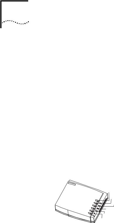
Router 3012 |
Figure 1 illustrates the Router 3012. |
|
|
Figure 1 Router 3012 |
|
Power LED
100M Ethernet LED
SERIAL0 LED
SERIAL1 LED
AUX LED
System LED

8 CHAPTER 1: INTRODUCING THE ROUTER 3000 FAMILY
Figure 2 illustrates the back panel of the Router 3012.
Figure 2 Back Panel of the Router 3012
Power |
Power |
AUX |
Grounding |
|
||
switch |
input |
|
port |
screw |
|
|
|
|
|
||||
|
socket |
Console 100M |
SERIAL0 |
SERIAL1 |
||
|
|
|
|
|
||
port |
Ethernet |
|
port |
||
|
System Specifications Table 3 lists system specifications for the Router 3012.
Table 3 System Specifications for the Router 3012
Item |
Description |
|
|
Fixed ports |
1 10/100 Mbps Ethernet port |
|
2 synchronous/asynchronous serial ports |
|
1 AUX port |
|
1 console port |
|
|
Processor |
MPC860T 50M Hz |
|
|
SDRAM |
64 MB |
|
|
Flash memory |
8 MB |
|
|
Maximum power |
20 W |
|
|
Power supply (external) |
Input voltage and frequency: 100 to 240V AC (the actual range can |
|
be 80 to 264 V) 50/60 Hz |
|
Input current: 0.5 A to 1 A |
|
|
|
Output voltage: 12 V |
|
Output current: 4 A |
|
|
Dimensions (W X H X |
251 X 42.5 X 187 mm (9.9X 1.7 X 7.4 in) |
D, highest arc points of |
|
the plastic panel) |
|
|
|
Weight |
0.75 kg (1.65 lb) |
|
|
Operating temperature |
0 to 400 C (32 to 1040 F) |
Relative humidity |
5 to 85% (noncondensing) |
|
|
LEDs Table 4 lists and describes the LEDs on the front panel of the Router 3012.
Table 4 Router 3012 LEDs
LED |
Description |
|
|
POWER |
Off —The power is off. |
|
Green — The power is on. |
|
|
100M ETH |
Off — The link is not connected. |
|
Flashing green — Data is being transmitted through the Ethernet |
|
port. |
|
|
SERIAL0 |
Off — The link is not connected. |
|
Green — The link is connected. |
|
Flashing green — Data is being transmitted through serial port 0. |
|
|

Router 3012 |
9 |
Table 4 Router 3012 LEDs (continued)
LED |
Description |
|
|
SERIAL1 |
Off — The link is not connected. |
|
Green — The link is connected. |
|
Flashing green — Data is being transmitted over serial port 1. |
|
|
AUX |
Off — The link is not connected. |
|
Green — The link is connected. |
|
Flashing green — Data is being transmitted over the AUX port. |
|
|
SYSTEM |
Flashing green — The system is operating normally. |
|
Always green or off — The system is not operating normally. |
|
|
Port Attributes The Router 3012 provides a console port, an AUX port, a 10/100M Ethernet port and a synchronous/asynchronous serial port. The attributes of these ports are described in the following sections.
Console Port
Table 5 lists attributes of the console port.
Table 5 Attributes of the Console Port
Attribute |
Description |
|
|
Connector |
RJ-45 |
|
|
Port standard |
Asynchronous EIA/TIA-232 |
|
|
Baud rate |
9.6 to 115.2 kbps (the default is 9.6 kbps) |
|
|
Services |
Connects with character terminal |
|
Connects with the serial ports of the local PCs and runs the terminal |
|
emulation program on the PCs |
|
Command line interface |
|
|
AUX Port
Table 6 lists attributes of the AUX port.
Table 6 Attributes of the AUX Port
Attribute |
Description |
|
|
Connector |
RJ-45 |
|
|
Port standard |
Asynchronous EIA/TIA-232 |
|
|
Baud rate |
300 bps to 115.2 kbps |
|
|
Services |
Modem dial-up |
|
Backup |
|
|
Protocols |
PPP (Point to Point Protocol) |
|
SLIP (Serial Line Internet Protocol) |
|
MP (Multilink PPP) |
|
|

10 CHAPTER 1: INTRODUCING THE ROUTER 3000 FAMILY
Ethernet Port
Table 7 lists attributes of the Ethernet port.
Table 7 Attributes of the Fast Ethernet Port
Attribute |
Description |
|
|
Connector |
RJ-45 |
|
|
Frame format |
Ethernet_II |
|
Ethernet_SNAP |
|
IEEE 802.2 |
|
IEEE 802.3 |
|
|
Operating mode |
10/100 Mbps autosensing |
|
Full duplex/half duplex |
|
|
Network protocol |
IP (Internet Protocol) |
|
Novell IPX (Internet Packet Exchange) |
|
|
Synchronous/Asynchronous Serial Port
Table 8 lists attributes of the serial port.
Table 8 Attributes of the Serial Port
|
Description |
|
|
|
|
|
|
|
|
|
|
Attribute |
Synchronous |
|
|
Asynchronous |
|
|
|
|
|
|
|
Connector |
DB50 |
|
|
|
|
|
|
|
|
|
|
Port standard and |
V.24 |
V.35 |
EIA/TIA-449, X.21 and |
V.24 (EIA/TIA-232) |
|
operating mode |
(EIA/TIA-23 |
|
EIA-530 |
|
|
|
2) |
|
|
|
|
|
|
|
|
|
|
|
DTE, DCE |
DTE, DCE |
DTE |
DCE |
|
|
|
|
|
|
|
Minimum baud |
1200 |
1200 |
1200 |
1200 |
300 |
rate (bps) |
|
|
|
|
|
|
|
|
|
|
|
Maximum baud |
64 k |
2.048 M |
2.048 M |
2.048 M |
115.2 K |
rate (bps) |
|
|
|
|
|
|
|
|
|
|
|
Services |
DDN leased line |
|
|
Modem dial-up |
|
|
Terminal access |
|
|
Backup |
|
|
Backup |
|
|
|
|
|
|
|
|
|
|
Protocols |
PPP |
|
|
|
PPP |
|
MP |
|
|
|
SLIP |
|
LAPB (Link Access Protocol-Balanced) |
|
MP |
||
|
HDLC (High-level Data Link Control) |
|
|
||
|
SDLC (Synchronous Data Link Control) |
|
|
||
|
X.25 |
|
|
|
|
|
Frame Relay |
|
|
|
|
|
|
|
|
|
|
Router 3013 and |
The Router 3013 and Router 3015 offer ISDN BRI support. The Router 3013 has an |
Router 3015 |
ISDN BRI S/T port and the Router 3015 has an ISDN BRI U port. |
|
Figure 3 illustrates the Router 3013 and Router 3015 routers. |
Router 3013 and Router 3015 11
Figure 3 Router 3013 and Router 3015
Power LED
100M Ethernet LED
Serial LED
BRI LED
AUX LED
System LED
Figure 4 illustrates the back panel of the Router 3013 and 3015.
Figure 4 Back Panel of the Router 3013 and Router 3015
|
CON AUX 100M ETH |
SERIAL |
BRI |
OFF |
ON DC12V |
|
|
|
|
|
|
CON |
|
|
|
|
BRI port |
|
|
|
|
|
|
|
|
||
Power |
|
|
|
100M |
Grounding |
||||
|
|
|
|
||||||
switch |
|
port |
Ethernet |
screw |
|
||||
Power |
|
AUX |
port |
SERIAL0 |
|
||||
|
|
||||||||
input |
|
port |
|
|
|
|
|
||
socket |
|
|
|
|
|
|
|||
|
|
|
|
|
|
|
|||
System Specifications Table 9 lists system specifications for the Router 3013 and Router 3015.
Table 9 System Specifications for the Router 3013 and Router 3015
Item |
Router 3013 Description |
Router 3015 Description |
|
|
|
Fixed ports |
1 console port |
1 console port |
|
1 10/100M Ethernet port |
1 10/100M Ethernet port |
|
1 AUX port |
1 AUX port |
|
1 synchronous/asynchronous |
1 synchronous/asynchronous serial port |
|
serial port |
1 ISDN BRI U port |
|
1 ISDN BRI S/T port |
|
|
|
|
|
|
|
Processor |
MPC860T 50 MHz |
|
|
|
|
SDRAM |
64 MB |
|
|
|
|
Flash memory |
8 MB |
|
|
|
|
Maximum |
20 W |
|
power |
|
|
|
|
|
Power supply |
Input voltage and frequency: 100 to 240V AC (the actual range can be 80 to |
|
(external) |
264 V) 50/60 Hz |
|
|
Input current: 0.5 A to 1A |
|
|
|
|
|
Output voltage: 12 V |
|
|
Output current: 4 A |
|
|
|
|
Dimensions (W |
251 X 42.5 X 187mm (9.9 X 1.7 X 7.4 in) |
|
X H X D, the |
|
|
highest arc |
|
|
points of the |
|
|
plastic panel) |
|
|
|
|
|
Weight |
0.75 kg (1.65 lb) |
|
|
|
|
Operating |
0 to 40 C (32 to 1040 F) |
|
temperature |
|
|
|
|
|

12 CHAPTER 1: INTRODUCING THE ROUTER 3000 FAMILY
Table 9 System Specifications for the Router 3013 and Router 3015 (continued)
Item |
Router 3013 Description |
Router 3015 Description |
|
|
|
Operating |
5 to 85% (noncondensing) |
|
humidity |
|
|
|
|
|
LEDs Table 10 lists and describes the LEDs on the front panel of the Router 3013 and Router 3015.
Table 10 Router 3013 and Router 3015 LEDs
LED |
Description |
|
|
POWER |
Off — The power is not on. |
|
Green — The power is on. |
|
|
100M ETH |
Off — The link is not connected. |
|
Flashing green — Data is being transmitted over the Ethernet port. |
|
|
SERIAL |
Off — The link is not connected. |
|
Green — The link is connected. |
|
Flashing green — Data is being transmitted over the serial port. |
|
|
BRI |
Off — No data is being transmitted over the ISDN BRI port and two B |
|
channels are free. |
|
Flashing green — Data is being transmitted over the ISDN BRI port. |
|
|
AUX |
Off — The link is not connected. |
|
Green means — The link is connected. |
|
Flashing green — Data is being transmitted over the AUX port. |
|
|
SYSTEM |
Flashing green — The system is operating normally. |
|
Always green or off — The system is not operating normally. |
|
|
Port Attributes The Router 3013 provides a console port, an AUX port, a 10/100M Ethernet port, a synchronous/asynchronous serial port, and an ISDN S/T port.
The Router 3015 provides a console port, an AUX port, a 10/100M Ethernet port, a synchronous/asynchronous serial port, and an ISDN U port.
Console Port
Table 11 lists attributes of the console port.
Table 11 Attributes of the Console Port
Attribute |
Description |
|
|
Connector |
RJ-45 |
|
|
Port standard |
Asynchronous EIA/TIA-232 |
|
|
Baud rate |
9.6 to 115.2 kbps (9.6 kbps is the default) |
|
|
Services |
Connects with terminal |
|
Connects with serial ports of the local PCs and runs the terminal |
|
emulation program on the PCs |
|
Command line interface |
|
|

Router 3013 and Router 3015 13
AUX Port
Table 12 lists attributes of the AUX port.
Table 12 Attributes of the AUX Port
Attribute |
Description |
|
|
Connector |
RJ-45 |
|
|
Port standard |
Asynchronous EIA/TIA-232 |
|
|
Baud rate |
300 bps to 115.2 kbps |
|
|
Services |
Modem dial-up |
|
Backup |
|
|
Protocols |
PPP (Point to Point Protocol) |
|
SLIP (Serial Line Internet Protocol) |
|
MP (Multilink PPP) |
|
|
Ethernet Port
Table 13 lists attributes of the Ethernet port.
Table 13 Attributes of the Fast Ethernet Port
Attribute |
Description |
|
|
Connector |
RJ-45 |
|
|
Frame format |
Ethernet_II |
|
Ethernet_SNAP |
|
IEEE 802.2 |
|
IEEE 802.3 |
|
|
Operating mode |
10/100 Mbps autosensing |
|
Full duplex/half duplex |
|
|
Network protocol |
IP (Internet Protocol) |
|
Novell IPX (Internet Packet Exchange) |
|
|
Synchronous/Asynchronous Serial Port
Table 14 lists attributes of the serial port.
Table 14 Attributes of the Serial Port
|
Description |
|
|
|
|
|
|
|
|
|
|
|
|
Attribute |
Synchronous |
|
|
|
Asynchronous |
|
|
|
|
|
|
|
|
Connector |
DB50 |
|
|
|
|
|
|
|
|
|
|
|
|
Port standard and |
V.24 |
V.35 |
EIA/TIA-449, |
X.21 and |
V.24 (EIA/TIA-232) |
|
operating mode |
(EIA/TIA-23 |
|
EIA-530 |
|
|
|
|
2) |
|
|
|
|
|
|
|
|
|
|
|
|
|
DTE, DCE |
DTE, DCE |
DTE |
|
DCE |
|
|
|
|
|
|
|
|
Minimum baud |
1200 |
1200 |
1200 |
|
1200 |
300 |
rate (bps) |
|
|
|
|
|
|
|
|
|
|
|
|
|
Maximum baud |
64 K |
2.048 M |
2.048 M |
|
2.048 M |
115.2 K |
rate (bps) |
|
|
|
|
|
|
|
|
|
|
|
|
|
Services |
DDN leased line |
|
|
|
Modem dial-up |
|
|
Terminal access |
|
|
|
Backup |
|
|
Backup |
|
|
|
|
|
|
|
|
|
|
|
|
14 CHAPTER 1: INTRODUCING THE ROUTER 3000 FAMILY
Table 14 Attributes of the Serial Port (continued)
|
Description |
|
|
|
|
Attribute |
Synchronous |
Asynchronous |
|
|
|
Protocols |
PPP |
PPP |
|
MP |
SLIP |
|
LAPB (Link Access Protocol-Balanced) |
MP |
|
HDLC (High-level Data Link Control) |
|
|
SDLC (Synchronous Data Link Control) |
|
|
X.25 |
|
|
Frame Relay |
|
|
|
|
ISDN S/T and ISDN U Ports
Table 15 lists attributes of the ISDN S/T and ISDN U ports.
Table 15 Attributes of ISDN S/T and U Ports
Attribute |
Description |
|
|
Connector |
RJ-45 |
|
|
Protocol standards |
Complies with ITU-T I.430, Q.921 and Q.931 recommendations |
|
|
Operating mode |
ISDN dial-up |
|
ISDN leased line |
|
|
Services |
ISDN |
|
ISDN additional services |
|
Multi-subscriber number |
|
Subaddress |
|
Backup |
|
|
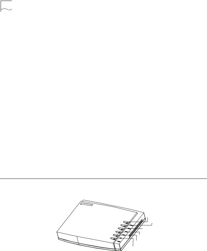
Router 3016 and |
Figure 5 illustrates the Router 3016. |
Router 3018 |
Figure 5 Router 3016 |
|
Power LED
Ethernet LED
T1-LNK LED
T1-ACT LED
AUX LED
System LED
Figure 6 illustrates the back panel of the Router 3016.

Router 3016 and Router 3018 15
Figure 6 Back Panel of the Router 3016
CON AUX 100METH |
|
CT1/PRI |
OFF ON |
|
|
Power |
CON |
100M |
Grounding |
switch |
|||
Power |
port |
Ethernet screw |
|
|
port |
CT1/PRI |
|
input |
AUX |
port |
|
socket |
|
||
|
port |
|
|
Figure 7 illustrates the Router 3018.
Figure 7 Router 3018
Power LED
Ethernet LED
E1 Link LED
E1 ACT LED
AUX LED
System LED
Figure 8 illustrates the back panel of the Router 3018.
Figure 8 Back Panel of the Router 3018
Power |
|
|
CON |
100M |
|
E1/CE1/PRI |
Port impedance |
|
|
||||||
switch |
port |
Ethernet |
port |
||||
Power |
|
port Grounding |
toggling button |
||||
|
|
||||||
input |
AUX |
screw |
|
|
|||
|
|
|
|
||||
socket port
System Specifications Table 16 lists system specifications for the Router 3016 and Router 3018.
Table 16 System Specifications for the Router 3016 and Router 3018
Item |
Router 3016 Description |
Router 3018 Description |
||
|
|
|
||
Fixed ports |
1 console port |
1 console port |
||
|
1 |
10/100 Mbps Ethernet port |
1 |
10/100 Mbps Ethernet port |
|
1 |
AUX port |
1 |
AUX port |
|
1 |
CT1/PRI port |
1 |
E1/CE1/PRI port |
|
|
|
|
|
Button |
|
|
1 |
E1/CE1/PRI port impedance |
|
|
|
toggling button |
|
|
|
|
|
|
Processor |
MPC860T 50 MHz |
|
|
|
|
|
|
|
|
SDRAM |
64 MB |
|
|
|
|
|
|
|
|
Flash memory |
8 |
MB |
|
|
|
|
|
|
|

16 CHAPTER 1: INTRODUCING THE ROUTER 3000 FAMILY
Table 16 System Specifications for the Router 3016 and Router 3018 (continued)
Item |
Router 3016 Description |
Router 3018 Description |
|
|
|
Maximum power |
20 W |
|
|
|
|
Power supply (external) |
Input voltage and frequency: 100 to 240V AC (the actual range can |
|
|
be 80 to 264 V) 50/60 Hz |
|
|
Input current: 0.5A to 1A |
|
|
Output voltage: 12 V |
|
|
Output current: 4 A |
|
|
|
|
Dimensions (W X H X D, |
251 X 42.5 X 187 mm (9.9 X 1.7 X 7.4 in) |
|
the highest arc points |
|
|
of the plastic panel) |
|
|
|
|
|
Weight |
0.75 kg (1.65 lb) |
|
|
|
|
Operating temperature |
0 to 400 C (32 to 1040 F) |
|
Operating humidity |
5 to 85% (noncondensing) |
|
|
|
|
LEDs Table 17 lists and describes the LEDs on the Router 3016 and Router 3018.
Table 17 Router 3016 LEDs
LED |
Description |
|
|
POWER |
Off — The power is not on. |
|
Green — The power is on. |
|
|
100M ETH |
Off — The link is not connected. |
|
Flashing green — Data is being being transmitted over the Ethernet |
|
port. |
|
|
T1-LNK/E1-LNK |
Off — The link is not set up. |
|
Green means — The link has been set up. |
|
|
T1-ACT/E1-ACT |
Off — No data is being transmitted through the port. |
|
Green — Data is being transmitted through the port. |
|
|
AUX |
Off — No data is being transmitted through the AUX port. |
|
Green — The link is connected. |
|
Flashing green — Data is being transmitted through the AUX port. |
|
|
SYSTEM |
Flashing green — The system is operating normally. |
|
On or off — The system is not operating normally. |
|
|
Port Attributes The Router 3016 provides a console port, an AUX port, a 10/100 Mbps Ethernet port, and a CT1/PRI port.
The Router 3018 provides a console port, an AUX port, a 10/100 Mbps Ethernet port, and a E1/CE1/PRI port.
Console Port
Table 18 lists attributes of the console port.
Table 18 Attributes of the Console Port
Attribute |
Description |
|
|
Connector |
RJ-45 |
|
|
Port standard |
Asynchronous EIA/TIA-232 |
|
|

Router 3016 and Router 3018 17
Table 18 Attributes of the Console Port (continued)
Attribute |
Description |
|
|
Baud rate |
9.6 to 115.2 kbps (the default is 9.6 kbps) |
|
|
Services |
Connects with character terminal |
|
Connects with serial ports of the local PCs and runs the terminal |
|
emulation program on the PCs |
|
Command line interface |
|
|
AUX Port
Table 19 lists attributes of the AUX port.
Table 19 Attributes of the AUX Port
Attribute |
Description |
|
|
Connector |
RJ-45 |
|
|
Port standard |
Asynchronous EIA/TIA-232 |
|
|
Baud rate |
300 bps to 115.2 kbps |
|
|
Services |
Modem dial-up |
|
Backup |
|
|
Protocols |
PPP (Point to Point Protocol) |
|
SLIP (Serial Line Internet Protocol) |
|
MP (Multilink PPP) |
|
|
Ethernet Port
Table 20 lists attributes of the Ethernet port.
Table 20 Attributes of the Ethernet Port
Attribute |
Description |
|
|
Connector |
RJ-45 |
|
|
Frame format |
Ethernet_II |
|
Ethernet_SNAP |
|
IEEE 802.2 |
|
IEEE 802.3 |
|
|
Operating mode |
10/100 Mbps autosensing |
|
Full duplex/half duplex |
|
|
Network protocol |
IP (Internet Protocol) |
|
Novell IPX (Internet Packet Exchange) |
|
|
CT1/PRI and E1/CE1/PRI Ports
Table 21 lists attributes of the CT1/PRI and and E1/CE1/PRI ports.
Table 21 Attributes of the CT1/PRI Port
Attribute |
CT1/PRI Description |
E1/CE1/PRI Description |
|
|
|
Connector |
RJ-45 |
DB15 |
|
|
|
Port standard |
G.703/T1 102 and G.704 |
|
|
|
|
Port rate |
1.544 Mbps |
2.048 Mbps |
|
|
|

18 CHAPTER 1: INTRODUCING THE ROUTER 3000 FAMILY
Table 21 Attributes of the CT1/PRI Port (continued)
Attribute |
CT1/PRI Description |
E1/CE1/PRI Description |
|
|
|
Operating mode |
Channelized T1 |
E1 |
|
Fractional T1 |
Channelized E1 |
|
ISDN PRI |
Fractional E1 |
|
|
ISDN PRI |
|
|
|
Services |
Backup |
|
|
Terminal access |
|
|
ISDN |
|
|
|
|
Protocols |
PPP |
|
|
MP |
|
|
HDLC |
|
|
LAPB |
|
|
X.25 (ITU-T X series Recommendations) |
|
|
Frame Relay |
|
|
Q.921 |
|
|
Q.931 |
|
|
Q.SIG |
|
|
|
|

INSTALLING THE ROUTER
2
There are two ways you can install your router:
■On a vertical surface
■On a workbench
The following sections describe how to prepare and install your router:
■Preparing to Install the Router
■Mounting the Router on a Vertical Surface
■Installing the Router on a Workbench
■Connecting the Protection Ground Wire
■Connecting the Power Cable
■Connecting the Router to the Console Terminal
■Connecting the Router to the Ethernet
■Connecting the Router to the WAN
■Verifying the Installation
Preparing to Install This section provides guidelines for preparing your site and router for installation. the Router
Safety Warnings Before installing your router, consider the following safety guidelines:
■Switch off the power supply before connecting the cables.
■Keep the router far away from any heat source.
■To ensure normal heat dissipation, do not stack routers.
■Do not keep a router in a damp place, and prevent liquid from getting into the router.
■Ensure that the neutral point of the power is grounded properly, to avoid personal injury.
■Ensure that the power is off before plugging or unplugging the interface cards, modules and cables of the router.
■Before removing the chassis, disconnect all the power cords and external cables.
■To avoid damage to the router, connect all the cables correctly. Never connect telephone cables (including the ISDN lines) to the console or AUX port.
20CHAPTER 2: INSTALLING THE ROUTER
■During the installation, wear an ESD (Electro-Static Discharge) preventive wrist strap and ESD-preventive gloves. See “Static Electricity” on page 20 for additional information on ESD prevention.
3Com recommends that you use an uninterrupted power supply (UPS) with your router.
General Site The environment of the installation site influences the performance and lifetime of Requirements the router. The installation site for your router should meet the following
requirements for temperature and humidity, dust, gases, static electricity, and electromagnetic discharge.
Temperature and Humidity
To ensure normal operation and to prolong the operational lifetime of the router, the temperature and humidity of the equipment room must be within controlled limits. The requirements for the temperature and humidity of the router installation site are listed in Table 22.
Table 22 Temperature and Humidity Requirements
Temperature |
Relative humidity |
|
|
00 to 400C (320 to 1040F) |
5% to 85% |
Dust
Dust is harmful to the safe operation of the router. The specifications for the dust content and diameter of the granule within the equipment room are listed in Table 23.
Table 23 Specification for Dust Content
Maximum diameter (µ m) |
0.5 |
1 |
3 |
5 |
|
|
|
|
|
Maximum density (the number |
1.4 x 10⁷ |
7 x 10⁵ |
2.4 x 10⁵ |
1.3 x 10⁵ |
of granules per cubic meter) |
|
|
|
|
|
|
|
|
|
Gases
The equipment room of the router must meet strict requirements for the content of salt, acid and sulfide. The specific limitation values of these harmful gases are given in Table 24.
Table 24 Harmful Gas Limitation Values in Equipment Room
Gas |
Average (mg/m3) |
Maximum (mg/m3) |
SO2 |
0.2 |
1.5 |
H2S |
0.0 |
0.03 |
NO2 |
0.04 |
0.15 |
NH3 |
0.05 |
0.15 |
Cl2 |
0.01 |
0.3 |
Static Electricity
To prevent damage caused by the static electricity, insure that:
■ The equipment is grounded
Preparing to Install the Router |
21 |
■The equipment room is dust-proof
■Adequate temperature and humidity conditions prevail
■The operator wears the ESD-preventive wrist strap, ESD-preventive gloves and ESD-preventive clothes while handling the circuit board.
■The dismantled circuit board is placed upward on the ESD preventive workbench, or put into an ESD preventive bag.
■You avoid direct contact with the elements of the circuit board.
Electromagnetic Discharge
To prevent damage by electromagnetic discharge, do the following:
■Take effective measures against electrical net interference for the power supply system.
■Separate the working ground of the router from the grounding device of the power equipment, or thunder proof grounding.
■Keep the router away from wireless launchers, radar launchers and other high frequency and high current equipment.
Lightning Damage
To minimize the risk of lightning damage do the following:
■Install a lightning arrester on the input end of a telephone cable, ISDN line or T1/E1 line.
■Ensure that the PGND wire of the chassis is well grounded
■Ensure that the neutral point of the socket of AC power supply is well grounded
■Install a lightning arrester at the input end of the power supply
Workbench Whether you install the router in a rack or place it directly on the workbench, it is Requirements necessary to ensure that:
■Airflow is not restricted around the router.
■The cabinet and workbench are strong enough to support the weight of the router and other installation accessories.
■The cabinet and workbench are well grounded.
Installation Checklist After you verify that the installation conditions comply with these requirements, open the packing case of the router and check the contents against the your order contract. Contact your Service representative if you find any discrepancies.
To install your router, you will need:
■Tools
■Phillips screwdriver
■Flat-head screwdriver
■ESD-preventive wrist strap and ESD-preventive gloves
■Flat-blade screws (used in wall mounting)
■Cables
Loading...