


2928

3Com Baseline Switch 2900 Family
User Guide
Baseline Switch 2920-SFP Plus
Baseline Switch 2928-SFP Plus
Baseline Switch 2952-SFP Plus
Baseline Switch 2928-PWR Plus
Baseline Switch 2928-HPWR Plus
Manual Version:
6W102-20090810
www.3com.com
3Com Corporation
350 Campus Drive, Marlborough,
MA, USA 01752 3064

Copyright © 2009, 3Com Corporation. All rights reserved. No part of this documentation may be reproduced in
any form or by any means or used to make any derivative work (such as translation, transformation, or
adaptation) without written permission from 3Com Corporation.
3Com Corporation reserves the right to revise this documentation and to make changes in content from time to
time without obligation on the part of 3Com Corporation to provide notification of such revision or change.
3Com Corporation provides this documentation without warranty, term, or condition of any kind, either implied
or expressed, including, but not limited to, the implied warranties, terms or conditions of merchantability,
satisfactory quality, and fitness for a particular purpose. 3Com may make improvements or changes in the
product(s) and/or the program(s) described in this documentation at any time.
If there is any software on removable media described in this documentation, it is furnished under a license
agreement included with the product as a separate document, in the hard copy documentation, or on the
removable media in a directory file named LICENSE.TXT or !LICENSE.TXT. If you are unable to locate a copy,
please contact 3Com and a copy will be provided to you.
UNITED STATES GOVERNMENT LEGEND
If you are a United States government agency, then this documentation and the software described herei n are
provided to you subject to the following:
All technical data and computer software are commercial in nature and developed solely at private expense.
Software is delivered as “Commercial Computer Software” as defined in DFARS 252.227-7014 (June 1995) or
as a “commercial item” as defined in FAR 2.101(a) and as such is provided with only such rights as are
provided in 3Com’s standard commercial license for the Software. Technical data is provided with limited rights
only as provided in DFAR 252.227-7015 (Nov 1995) or FAR 52.227-14 (June 1987), whichever is applicable.
You agree not to remove or deface any portion of any legend provided on any licensed program or
documentation contained in, or delivered to you in conjunction with, this User Guide.
Unless otherwise indicated, 3Com registered trademarks are registered in the United States and may or may
not be registered in other countries.
3Com and the 3Com logo are registered trademarks of 3Com Corporation.
All other company and product names may be trademarks of the respective companies with which they are
associated.
ENVIRONMENTAL STATEMENT
It is the policy of 3Com Corporation to be environmentally-friendly in all operations. To uphold our policy, we
are committed to:
Establishing environmental performance standards that comply with national legislation and regulations.
Conserving energy, materials and natural resources in all operations.
Reducing the waste generated by all operations. Ensuring that all waste conforms to recognized environmental
standards. Maximizing the recyclable and reusable content of all products.
Ensuring that all products can be recycled, reused and disposed of safely.
Ensuring that all products are labelled according to recognized environmental standards.
Improving our environmental record on a continual basis.
End of Life Statement
3Com processes allow for the recovery, reclamation and safe disposal of all end-of-life electronic components.
Regulated Materials Statement
3Com products do not contain any hazardous or ozone-depleting material.
Environmental Statement about the Documentation
The documentation for this product is printed on paper that comes from sustainable, managed forests; it is fully
biodegradable and recyclable, and is completely chlorine-free. The varnish is environmentally-friendly, and the
inks are vegetable-based with a low heavy-metal content.

About This Manual
Organization
3Com Baseline Switch 2900 Family User Guide is organized as follows:
Part Contents
1 Overview Perform overview of 3Com baseline switch 2900 family.
2 Configuration Wizard Perform quick configuration of the device.
3 IRF
Configure global parameters and stack ports, and display global
settings, port settings, and topology summary of a stack.
4 Summary
Display the basic system information, port information, system
resource state, and recent system operation logs.
5 Device Basic Information
Display and configure the system name and idle timeout period for
logged-in users.
6 System Time Display and configure the system date and time.
7 Log Management
Clear system logs, display and configure the loghost, display and
refresh system logs.
Display and configure the buffer capacity, and interval for refreshes
system logs.
8 Configuration
Management
Back up the configuration file or upload the configuration file to be
used at the next startup from the host of the current user to the device.
Save the current configuration to the configuration file to be used at
the next startup.
Restore the factory default settings.
9 Device Maintenance
Configure to upload upgrade file from local host, and upgrade the
system software.
Configure to reboot the device.
Display the electronic label of the device.
Generate diagnostic information file, and view or save the file to local
host.
10 File Management
Manage files on the device, such as displaying the file list,
downloading a file, uploading a file, and removing a file.
11 Port Management
Create, modify, delete, and enable/disable a port, and clear port
statistics.
12 Port Mirroring Create, remove, and configure a port mirroring group.
13 User Management
Create, modify, and remove an FTP or Telnet user, and display the
brief information of FTP and Telnet users.
14 Loopback Test Perform loopback tests on Ethernet interfaces.
15 VCT Check the status of the cables connected to Ethernet ports.
16 Flow Interval
Set an interval for collecting traffic statistics on interfaces, and display
the average rate at which the interface receives and sends packets
within a specified time interval.
17 Storm Constrain
Display, create, modify, and remove the port traffic threshold, and
display or set the interval for collecting storm constrain statistics.

Part Contents
18 RMON
Configure RMON, and dissplay, create, modify, and clear RMON
statistics.
19 Energy Saving Display and configure the energy saving settings of an interface.
20 SNMP
Configure SNMP, and dissplay, create, modify, and clear SNMP
statistics.
21 Interface Statistics Display and clear the statistics information of an interface.
22 VLAN Create VLANs, and display the VLAN-related details of a port.
23 VLAN Interface
Create VLAN interfaces, configure IP addresses for them, and Display
information about VLAN interfaces by address type.
24 Voice VLAN Configure the global voice VLAN or a voice VLAN on a port.
25 MAC Address
Create and remove MAC addresses, display MAC address
information.
26 MSTP Configure MSTP.
27 Link Aggregation and
LACP
Create, modify and remove link aggregation groups, and set LACP
priorities.
28 LLDP Configure LLDP.
29 IGMP Snooping Configure IGMP snooping globally or in a VLAN, or on a port.
30 Routing
Create an IPv4 static route, dlete the selected IPv4 static routes, and
display the IPv4 active route table.
31 DHCP Configure DHCP Relay or DHCP Snooping
32 Service Management
Enable or disable services, set related parameters, and displays the
states of services.
33 Diagnostic Tools Ping an IPv4 address, or perform trace route operations.
34 ARP
Add, modify, remove, and display ARP entries.
Configure and display gratuitous ARP.
35 802.1X
Configure 802.1X globally or on a port, and display 802.1X
configuration information globally or on a port.
36 AAA
Add and remove ISP domains, specify authentication /authorization
/accounting methods for an ISP domain.
37 RADIUS Display and configure RADIUS parameters.
38 User Create, modify and remove a local user or a user group.
39 PKI
Add, modify, and delete a PKI entity or a PKI domain.
Generate a key pair, destroy a key pair, retrieve a certificate, request a
certificate, and delete a certificate.
40 Port Isolation Group
Configure a port isolation group, and display port isolation group
information.
41 Authorized IP Configure and display authorized IP.
42 ACL-QoS Configure ACL rules and Qos Policy.
43 PoE
Configure a PoE interface, and display PSE information and PoE
interface information.
Conventions
The manual uses the following conventions:
Command conventions
Convention Description
Boldface
The keywords of a command line are in Boldface.
italic
Command arguments are in italic.
[ ] Items (keywords or arguments) in square brackets [ ] are optional.
{ x | y | ... }
Alternative items are grouped in braces and separated by vertical bars.
One is selected.
[ x | y | ... ]
Optional alternative items are grouped in square brackets and
separated by vertical bars. One or none is selected.
{ x | y | ... } *
Alternative items are grouped in braces and separated by vertical bars.
A minimum of one or a maximum of all can be selected.
[ x | y | ... ] *
Optional alternative items are grouped in square brackets and
separated by vertical bars. Many or none can be selected.
&<1-n>
The argument(s) before the ampersand (&) sign can be entered 1 to n
times.
# A line starting with the # sign is comments.
GUI conventions
Convention Description
< > Button names are inside angle brackets. For example, click <OK>.
[ ]
Window names, menu items, data table and field names are inside
square brackets. For example, pop up the [New User] window.
/
Multi-level menus are separated by forward slashes. For example,
[File/Create/Folder].
Symbols
Convention Description
Means reader be extremely careful. Improper operation may cause
bodily injury.
Means reader be careful. Improper operation may cause data loss or
damage to equipment.
Means a complementary description.

Related Documentation
In addition to this manual, each 3com Baseline Switch 2900 documentation set includes the following:
Manual Description
3Com Baseline Switch 2900 Family
Getting Started Guide
This guide provides all the information you need to install
and use the 3Com Baseline Switch 2900 Family.
Obtaining Documentation
You can access the most up-to-date 3Com product documentation on the World Wide Web at this URL:
http://www.3com.com.

i
Table of Contents
1 Overview·····················································································································································1-1
2 Configuration Through the Web Interface ······························································································2-1
Web-Based Network Management Operating Environment···································································2-1
Logging In to the Web Interface··············································································································2-1
Default Login Information ················································································································2-1
Example···········································································································································2-2
Logging Out of the Web Interface ···········································································································2-3
Introduction to the Web Interface············································································································2-3
Web User Level·······································································································································2-4
Introduction to the Web-Based NM Functions ························································································2-4
Introduction to the Controls on the Web Pages ····················································································2-11
Configuration Guidelines·······················································································································2-13
3 Configuration Through the Command Line Interface············································································3-1
Getting Started with the Command Line Interface··················································································3-1
Setting Up the Configuration Environment······················································································3-1
Setting Terminal Parameters···········································································································3-2
Logging In to the CLI ·······················································································································3-6
CLI Commands ·······································································································································3-6
initialize············································································································································3-6
ipsetup ·············································································································································3-7
password ·········································································································································3-8
ping··················································································································································3-8
quit···················································································································································3-9
reboot···············································································································································3-9
summary········································································································································3-10
upgrade ·········································································································································3-11
Configuration Example for Upgrading the Host Software Through the CLI··········································3-12

1-1
1 Overview
The 3Com baseline switch 2900 family can be configured through the command line interface (CLI),
web interface, and SNMP/MIB. These configuration methods are suitable for different application
scenarios.
z The web interface supports all switch 2900 series configurations.
z The CLI provides some configuration commands to facilitate your operation. To perform other
configurations not supported by the CLI, use the web interface.
2-1
2 Configuration Through the Web Interface
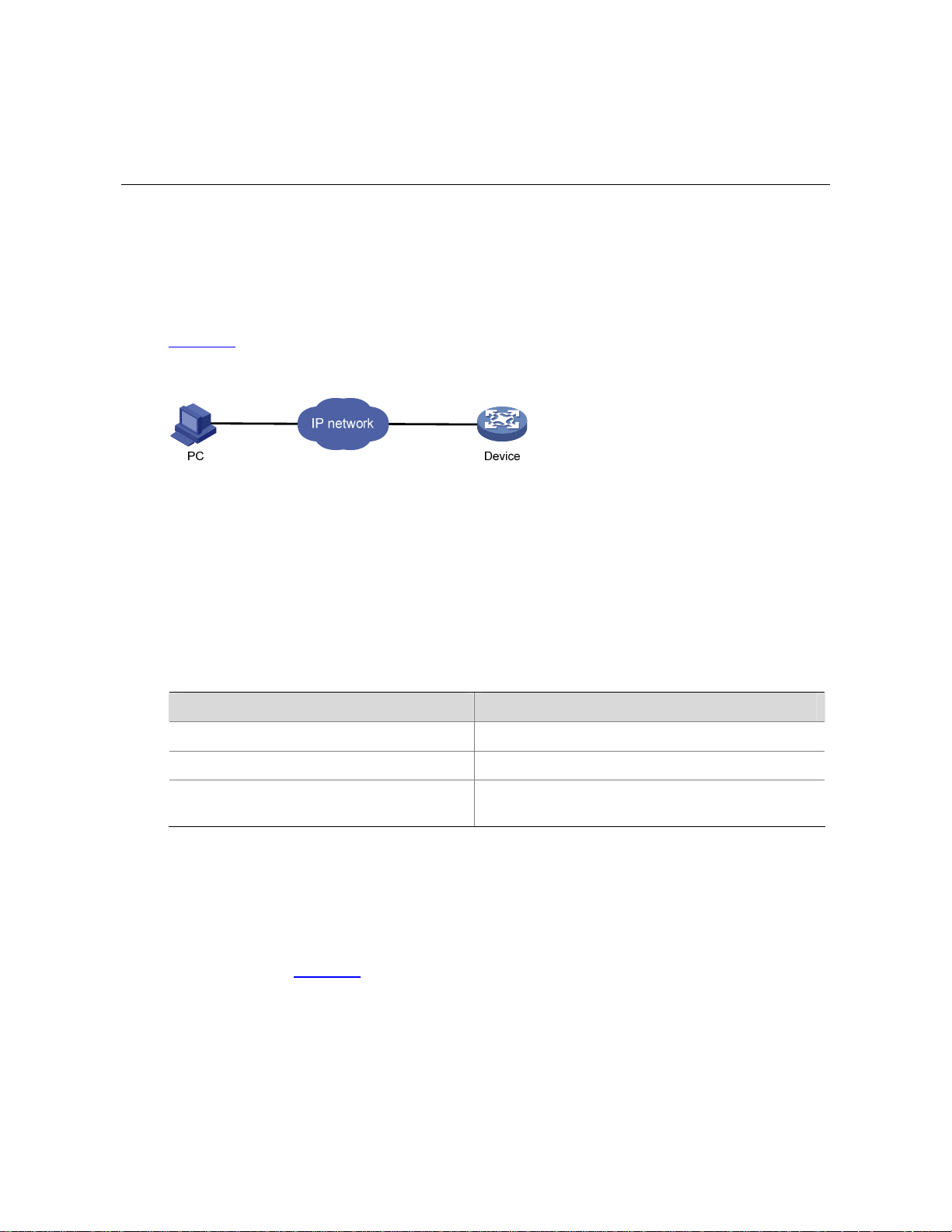
Web-Based Network Management Operating Environment
3Com provides the Web-based network management function to facilitate the operations and
maintenance on 3Com’s network devices. Through this function, the administrator can visually manage
and maintain network devices through the Web-based configuration interfaces.
Figure 2-1
shows a Web-based network management operating environment.
Figure 2-1 Web-based network management operating environment
Logging In to the Web Interface
Default Login Information
The device is provided with the default Web login information. You can use the default information to log
in to the Web interface.
Table 2-1 The default Web login information
Information needed at login Default value
Username admin
Password None
IP address of the device (VLAN-interface 1)
Default IP address of the device, depending on the
status of the network where the device resides.
1) The device is not connected to the network, or no DHCP server exists in the subnet where the
device resides
If the device is not connected to the network, or no DHCP server exists in the subnet where the device
resides, you can get the default IP address of the device on the label on the right of the device rear
panel, as shown in Figure 2-2
. The default subnet mask is 255.255.0.0.
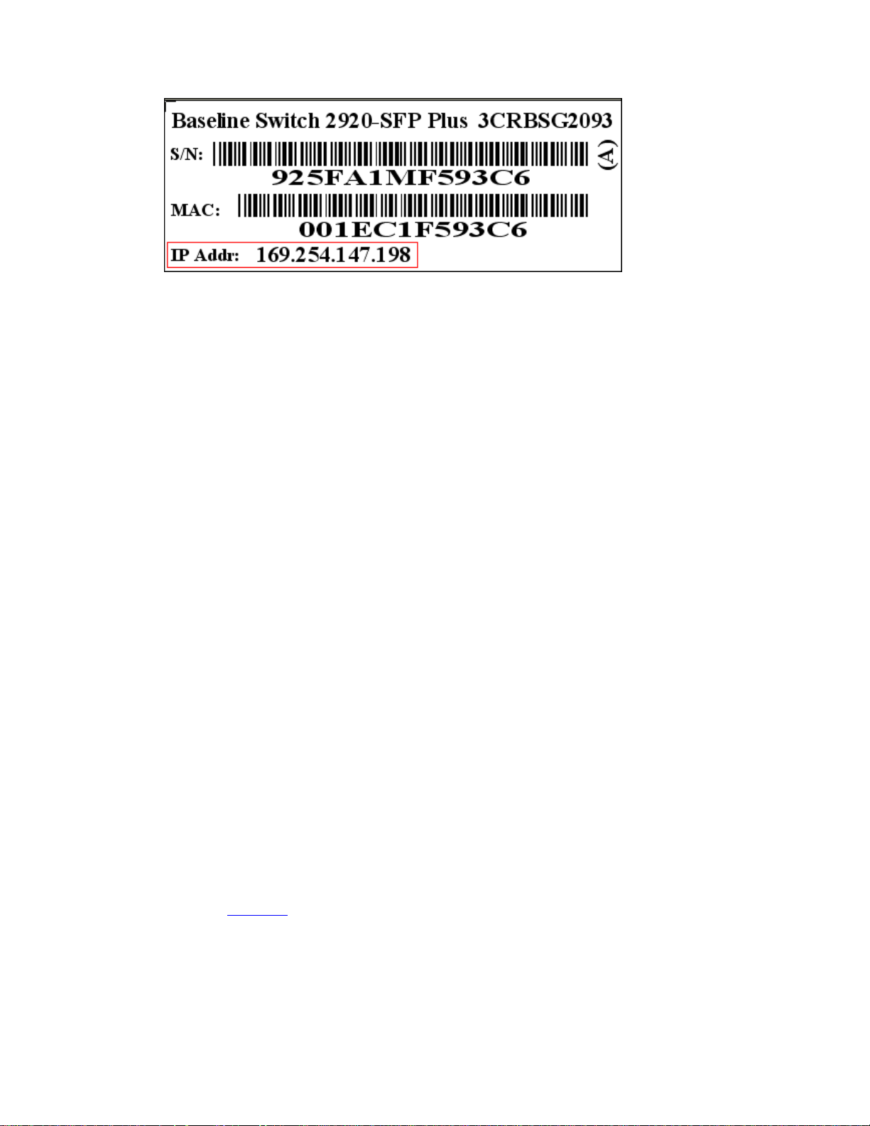
2-2
Figure 2-2 Default IP address of the device
2) A DHCP server exists in the subnet where the device resides
If a DHCP server exists in the subnet where the device resides, the device will dynamically obtain its
default IP address through the DHCP server. You can log in to the device through the console port, and
execute the summary command to view the information of its default IP address.
<Sysname> summary
Select menu option: Summary
IP Method: DHCP
IP address: 10.153.96.86
Subnet mask: 255.255.255.0
Default gateway: 0.0.0.0
<Omitted>
Example
Assuming that the default IP address of the device is 169.254.147.198, follow these steps to log in to the
device through the Web interface.
z Connect the device to a PC
Connect the GigabitEthernet interface of the device to a PC by using a crossover Ethernet cable (by
default, all interfaces belong to VLAN 1).
z Configure an IP address for the PC and ensure that the PC and device can communicate with each
other properly.
Select an IP address for the PC from network segment 169.254.0.0/16 (except for the default IP
address of the device), for example, 169.254.147.1.
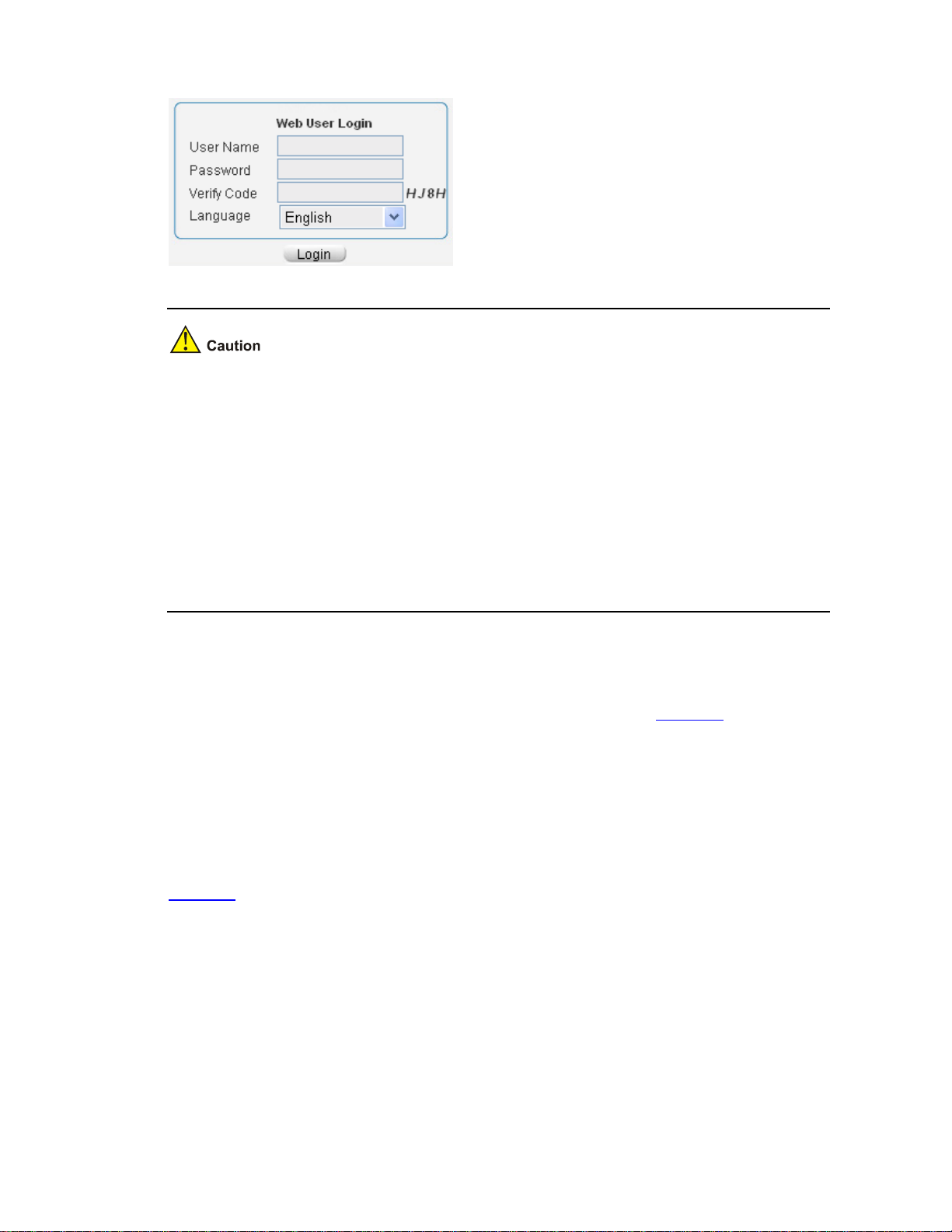
z Open the browser, and input the login information.
On the PC, open the browser (it is recommended to use IE 5.0 or later), type the IP address
http://169.254.147.198 in the address bar, and press Enter to enter the login page of the Web interface,
as shown in Figure 2-3
. Input the username admin and the verification code, leave the password blank,
select the language (English and Chinese are supported at present), and click Login.
2-3
Figure 2-3 Login page of the Web interface
z The PC where you configure the device is not necessarily a Web-based network management
terminal. A Web-based network management terminal is a PC used to log in to the Web interface
and is required to be reachable to the device.
z After logging in to the Web interface, you can select Device > Users from the navigation tree,
create a new user, and select Wizard or Network > VLAN interface to configure the IP address of
the VLAN interface acting as the management interface. For detailed configuration, refer to the
corresponding configuration manuals of these modules.
z If you click the verification code displayed on the Web login page, you can get a new verification
code.
z Up to five users can concurrently log in to the device through the Web interface.
Logging Out of the Web Interface
Click Logout in the upper-right corner of the Web interface, as shown in Figure 2-4 to quit the web
console.
The system does not save the current configuration automatically. Therefore, you are recommended to
save the current configuration before logout.
Introduction to the Web Interface
The Web interface is composed of three parts: navigation tree, title area, and body area, as shown in
Figure 2-4
.
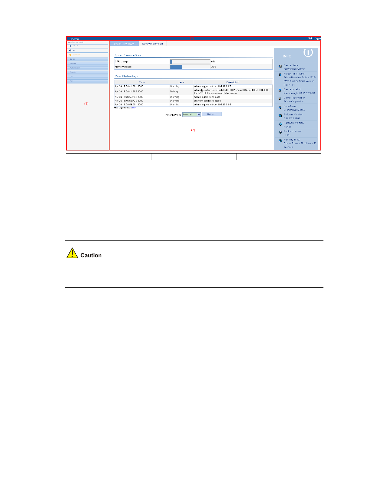
2-4
Figure 2-4 Web-based configuration interface
(1) Navigation tree (2) Body area (3) Title area
z Navigation tree: Organizes the Web-based NM functions as a navigation tree, where you can
select and configure functions as needed. The result is displayed in the body area.
z Body area: Allows you to configure and display features.
z Title area: Displays the path of the current configuration interface in the navigation tree; provides
the Help button to display the Web related help information, and the Logout button to log out of the
Web interface.
The Web network management functions not supported by the device will not be displayed in the
navigation tree.
Web User Level
Web user levels, from low to high, are visitor, monitor, configure, and management. A user with a
higher level has all the operating rights of a user with a lower level.
z Visitor: Users of this level can only use the network diagnostic tools ping and Trace Route. They
can neither access the device data nor configure the device.
z Monitor: Users of this level can only access the device data but cannot configure the device.
z Configure: Users of this level can access device data and configure the device, but they cannot
upgrade the host software, add/delete/modify users, or back up/restore configuration files.
z Management: Users of this level can perform any operations to the device.
Introduction to the Web-Based NM Functions
Table 2-2 describes the Web-based network management functions in detail.

2-5
User level in Table 2-2 indicates that users of this level or users of a higher level can perform the
corresponding operations.
Table 2-2 Description of Web-based NM functions
Function menu Description User level
Wizard IP Setup Perform quick configuration of the device. Management
Display global settings and port settings of a stack. Configure
Setup
Configure global parameters and stack ports. Management
Topology
Summary
Display the topology summary of a stack. Configure
IRF
Device
Summary
Display the control panels of stack members. Configure
System
Information
Display the basic system information, system
resource state, and recent system operation logs.
Monitor
Summary
Device
Information
Display the port information of the device. Monitor
System
Name
Display and configure the system name. Configure
Basic
Web Idle
Timeout
Display and configure the idle timeout period for
logged-in users.
Configure
Software
Upgrade
Configure to upload upgrade file from local host,
and upgrade the system software.
Management
Reboot Configure to reboot the device. Management
Electronic
Label
Display the electronic label of the device. Monitor
Device
Mainten
ance
Diagnostic
Information
Generate diagnostic information file, and view or
save the file to local host.
Management
System
Time
System
Time
Display and configure the system date and time. Configure
Display and refresh system logs. Monitor
Loglist
Clear system logs. Configure
Loghost Display and configure the loghost. Configure
Syslog
Log Setup
Display and configure the buffer capacity, and
interval for refreshes system logs.
Configure
Backup
Back up the configuration file to be used at the next
startup from the device to the host of the current
user.
Management
Devi
ce
Configur
ation
Restore
Upload the configuration file to be used at the next
startup from the host of the current user to the
device.
Management

2-6
Function menu Description User level
Save
Save the current configuration to the configuration
file to be used at the next startup.
Configure
Initialize Restore the factory default settings. Configure
File
Manage
ment
File
Manageme
nt
Manage files on the device, such as displaying the
file list, downloading a file, uploading a file, and
removing a file.
Management
Summary Display port information by features. Monitor
Detail
Displays feature information by ports. Monitor
Port
Manage
ment
Setup
Create, modify, delete, and enable/disable a port,
and clear port statistics.
Configure
Summary
Display the configuration information of a port
mirroring group.
Monitor
Create Create a port mirroring group. Configure
Remove Remove a port mirroring group. Configure
Port
Mirroring
Modify Port Configure ports for a mirroring group. Configure
Summary
Display the brief information of FTP and Telnet
users.
Monitor
Super
Password
Configure a password for a lower-level user to
switch from the current access level to the
management level.
Management
Create Create an FTP or Telnet user. Management
Modify Modify FTP or Telnet user information. Management
Remove Remove an FTP or a Telnet user. Management
Users
Switch To
Manageme
nt
Switch the current user level to the management
level.
Visitor
Loopbac
k
Loopback Perform loopback tests on Ethernet interfaces. Configure
VCT VCT
Check the status of the cables connected to
Ethernet ports.
Configure
Port Traffic
Statistics
Display the average rate at which the interface
receives and sends packets within a specified time
interval.
Monitor
Flow
Interval
Interval
Configurati
on
Set an interval for collecting traffic statistics on
interfaces.
Configure
Storm
Constrai
n
Storm
Constrain
Display and set the interval for collecting storm
constrain statistics.
Display, create, modify, and remove the port traffic
threshold.
Configure
Statistics Display, create, modify, and clear RMON statistics. Configure
History
Display, create, modify, and clear RMON history
sampling information.
Configure
RMON
Alarm View, create, modify, and clear alarm entries. Configure

2-7
Function menu Description User level
Event View, create, modify, and clear event entries. Configure
Log Display log information about RMON events. Configure
Energy
Saving
Energy
Saving
Display and configure the energy saving settings of
an interface.
Configure
Display and refresh SNMP configuration and
statistics information.
Monitor
Setup
Configure SNMP. Configure
Display SNMP community information. Monitor
Community
Create, modify and delete an SNMP community. Configure
Display SNMP group information. Monitor
Group
Create, modify and delete an SNMP group. Configure
Display SNMP user information. Monitor
User
Create, modify and delete an SNMP user. Configure
Display the status of the SNMP trap function and
information about target hosts.
Monitor
Trap
Enable or disable the SNMP trap function, or
create, modify and delete a target host.
Configure
Display SNMP view information. Monitor
SNMP
View
Create, modify and delete an SNMP view. Configure
Interface
Statistics
Interface
Statistics
Display and clear the statistics information of an
interface.
Configure
Select
VLAN
Select a VLAN range. Monitor
Create Create VLANs. Configure
Port Detail Display the VLAN-related details of a port. Monitor
Detail Displays the member port information of a VLAN. Monitor
Modify
VLAN
Modify the description and member ports of a
VLAN.
Configure
Modify Port Change the VLAN to which a port belongs. Configure
VLAN
Remove Remove VLANs. Configure
Summary
Display information about VLAN interfaces by
address type.
Monitor
Create
Create VLAN interfaces and configure IP
addresses for them.
Configure
Modify
Modify the IP addresses and status of VLAN
interfaces.
Configure
VLAN
Interface
Remove Remove VLAN interfaces. Configure
Summary
Display voice VLAN information globally or on a
port.
Monitor
Setup Configure the global voice VLAN. Configure
Net
work
Voice
VLAN
Port Setup Configure a voice VLAN on a port. Configure

2-8
Function menu Description User level
OUI
Summary
Display the addresses of the OUIs that can be
identified by voice VLAN.
Monitor
OUI Add
Add the address of an OUI that can be identified by
voice VLAN.
Configure
OUI
Remove
Remove the address of an OUI that can be
identified by voice VLAN.
Configure
Display MAC address information. Monitor
MAC
Create and remove MAC addresses. Configure
MAC
Setup
Display and configure MAC address aging time. Configure
Display information about MST regions. Monitor
Region
Modify MST regions. Configure
Global Set global MSTP parameters. Configure
Port
Summary
Displays the MSTP information of ports. Monitor
MSTP
Port Setup Set MSTP parameters on ports. Configure
Summary Display information about link aggregation groups. Monitor
Create Create link aggregation groups. Configure
Modify Modify link aggregation groups. Configure
Link
Aggrega
tion
Remove Remove link aggregation groups. Configure
Summary
Display information about LACP-enabled ports and
their partner ports.
Monitor
LACP
Setup Set LACP priorities. Configure
Display the LLDP configuration information, local
information, neighbor information, statistics
information, and status information of a port.
Monitor
Port Setup
Modify LLDP configuration on a port. Configure
Display global LLDP configuration information. Monitor
Global
Setup
Configure global LLDP parameters. Configure
Global
Summary
Display global LLDP local information and
statistics.
Monitor
LLDP
Neighbor
Summary
Displays global LLDP neighbor information. Monitor
Display global IGMP snooping configuration
information or the IGMP snooping configuration
information in a VLAN, and view the IGMP
snooping multicast entry information.
Monitor
Basic
Configure IGMP snooping globally or in a VLAN. Configure
Display the IGMP snooping configuration
information on a port.
Monitor
IGMP
Snoopin
g
Advanced
Configure IGMP snooping on a port. Configure
Summary Display the IPv4 active route table. Monitor IPv4
Routing
Create Create an IPv4 static route. Configure

2-9
Function menu Description User level
Remove Delete the selected IPv4 static routes. Configure
Display information about the DHCP status,
advanced configuration information of the DHCP
relay agent, DHCP server group configuration,
DHCP relay agent interface configuration, and the
DHCP client information.
Monitor
DHCP
Relay
Enable/disable DHCP, configure advanced DHCP
relay agent settings, configure a DHCP server
group, and enable/disable the DHCP relay agent
on an interface.
Configure
Display the status, trusted and untrusted ports and
DHCP client information of DHCP snooping.
Monitor
DHCP
DHCP
Snooping
Enable/disable DHCP snooping, and configure
DHCP snooping trusted and untrusted ports.
Configure
Displays the states of services: enabled or
disabled.
Configure
Service Service
Enable/disable services, and set related
parameters.
Management
Ping Ping an IPv4 address. Visitor
Diagnost
ic Tools
Trace
Route
Perform trace route operations. Visitor
Display ARP table information. Monitor
ARP Table
Add, modify, and remove ARP entries. Configure
Displays the configuration information of gratuitous
ARP.
Monitor
ARP
Manage
ment
Gratuitous
ARP
Configure gratuitous ARP. Configure
Display ARP detection configuration information. Monitor ARP
Anti-Atta
ck
ARP
Detection
Configure ARP detection. Configure
Display 802.1X configuration information globally
or on a port.
Monitor
802.1X 802.1X
Configure 802.1X globally or on a port. Configure
Display ISP domain configuration information. Monitor
Domain
Setup
Add and remove ISP domains. Management
Display the authentication configuration
information of an ISP domain.
Monitor
Authenticat
ion
Specify authentication methods for an ISP domain. Management
Display the authorization method configuration
information of an ISP domain.
Monitor
Authorizati
on
Specify authorization methods for an ISP domain. Management
Display the accounting method configuration
information of an ISP domain.
Monitor
AAA
Accounting
Specify accounting methods for an ISP domain. Management
Auth
entic
atio
n
RADIUS
RADIUS
Server
Display and configure RADIUS server information. Management

2-10
Function menu Description User level
RADIUS
Setup
Display and configure RADIUS parameters. Management
Display configuration information about local
users.
Monitor
Local User
Create, modify and remove a local user. Management
Display configuration information about user
groups.
Monitor
Users
User
Group
Create, modify and remove a user group. Management
Display information about PKI entities. Monitor
Entity
Add, modify, and delete a PKI entity. Configure
Display information about PKI domains. Monitor
Domain
Add, modify, and delete a PKI domain. Configure
Display the certificate information of PKI domains
and view the contents of a certificate.
Monitor
Certificate
Generate a key pair, destroy a key pair, retrieve a
certificate, request a certificate, and delete a
certificate.
Configure
Display the contents of the CRL. Monitor
PKI
CRL
Receive the CRL of a domain. Configure
Summary Display port isolation group information. Monitor Port
Isolate
Group
Modify Configure a port isolation group. Configure
Summary
Display the configurations of authorized IP, the
associated IPv4 ACL list, and the associated IPv6
ACL list.
Management
Sec
urity
Authoriz
ed IP
Setup Configure authorized IP. Management
Summary Display time range configuration information. Monitor
Create Create a time range. Configure
Time
Range
Remove Delete a time range. Configure
Summary Display IPv4 ACL configuration information. Monitor
Create Create an IPv4 ACL. Configure
Basic
Setup
Configure a rule for a basic IPv4 ACL. Configure
Advanced
Setup
Configure a rule for an advanced IPv4 ACL. Configure
Link Setup Create a rule for a link layer ACL. Configure
ACL
IPv4
Remove Delete an IPv4 ACL or its rules. Configure
Summary Display the queue information of a port. Monitor
Queue
Setup Configure a queue on a port. Configure
Summary Display line rate configuration information. Monitor
QoS
Line
Rate
Setup Configure the line rate. Configure

2-11
Function menu Description User level
Summary Display classifier configuration information. Monitor
Create Create a class. Configure
Setup Configure the classification rules for a class. Configure
Classifie
r
Remove Delete a class or its classification rules. Configure
Summary Display traffic behavior configuration information. Monitor
Create Create a traffic behavior. Configure
Setup Configure actions for a traffic behavior. Configure
Port Setup
Configuring traffic mirroring and traffic redirecting
for a traffic behavior
Configure
Behavior
Remove Delete a traffic behavior. Configure
Summary Display QoS policy configuration information. Monitor
Create Create a QoS policy. Configure
Setup
Configure the classifier-behavior associations for a
QoS policy.
Configure
QoS
Policy
Remove
Delete a QoS policy or its classifier-behavior
associations.
Configure
Summary Display the QoS policy applied to a port. Monitor
Setup Apply a QoS policy to a port. Configure
Port
Policy
Remove Remove the QoS policy from the port. Configure
Display priority mapping table information. Monitor
Priority
Mapping
Priority
Mapping
Modify the priority mapping entries. Configure
Display port priority and trust mode information. Monitor
Port
Priority
Port
Priority
Modify port priority and trust mode. Configure
Summary
Display PSE information and PoE interface
information.
Monitor
PoE PoE
Setup Configure a PoE interface. Configure
Introduction to the Controls on the Web Pages
Apply button
Click the button to submit and apply the input information.
Cancel button
Click the button to cancel the input information. The page changes to the display page of the function or
to the Device Info page.
Search button
Select an item to be queried, input the keyword, and click the Query button to display the items that
meet the requirements.
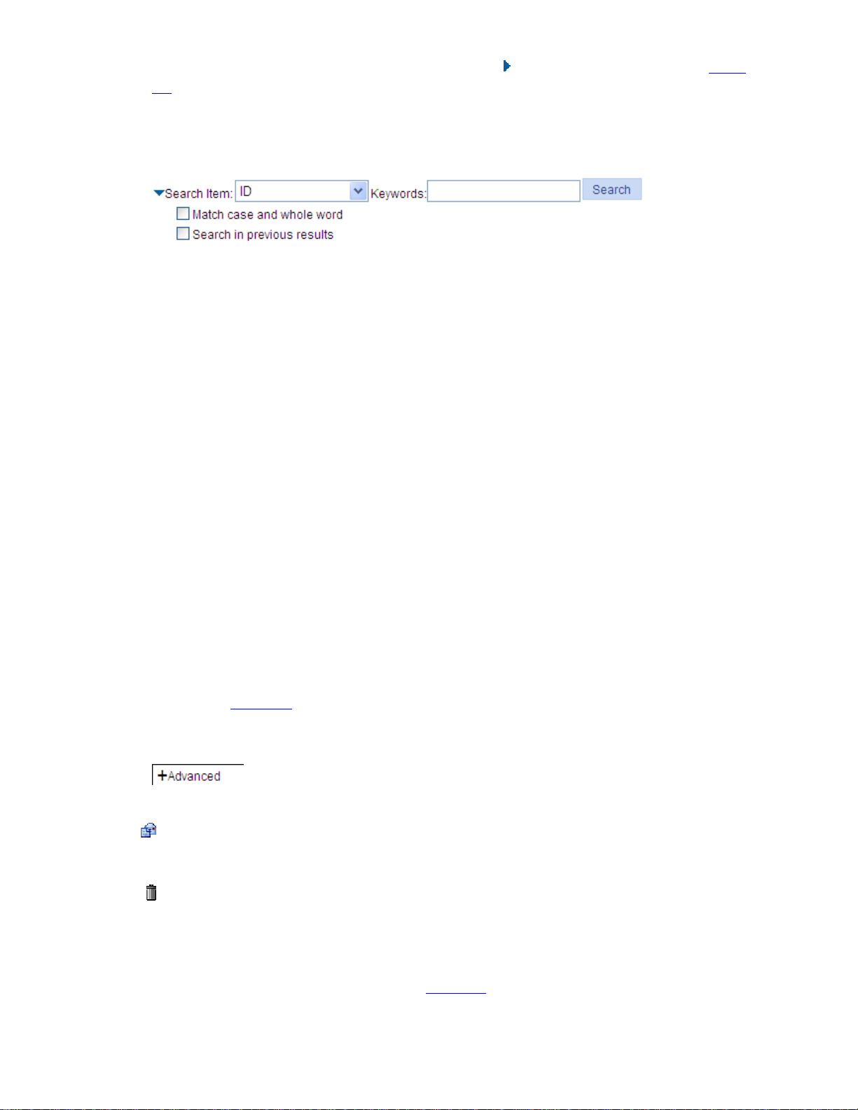
2-12
The advance search function is also provided. You can click before Search Item, as shown in Figure
2-5. You can select Match case and whole word, that is, the item to be searched must completely
match the keyword, or you can select Search in previous results. If you do not select exact search,
fuzzy search is performed.
Figure 2-5 Advanced search
Refresh button
Click the button to refresh the display information of the current page.
Clear button
Click the button to clear all the items in a list or all statistics.
Remove button
Click the button to remove the selected items.
Select All button
Click the button to select all the items in a list, or all the ports on the device panel.
Select None button
Click the button to deselect all the items in a list, or all the ports on the device panel.
Restore button
Click the button to restore all the items in the current configuration page to the system default.
Expand button
As shown in Figure 2-6, click the plus sign before a corresponding item. You can see the collapsed
contents.
Figure 2-6 Expand button
icon
Click the icon to enter the modification page of an item to modify the configurations of the item.
icon
Click the icon to delete the item corresponding to this icon.
Help button
Click the button to open the page, as shown in Figure 2-8.
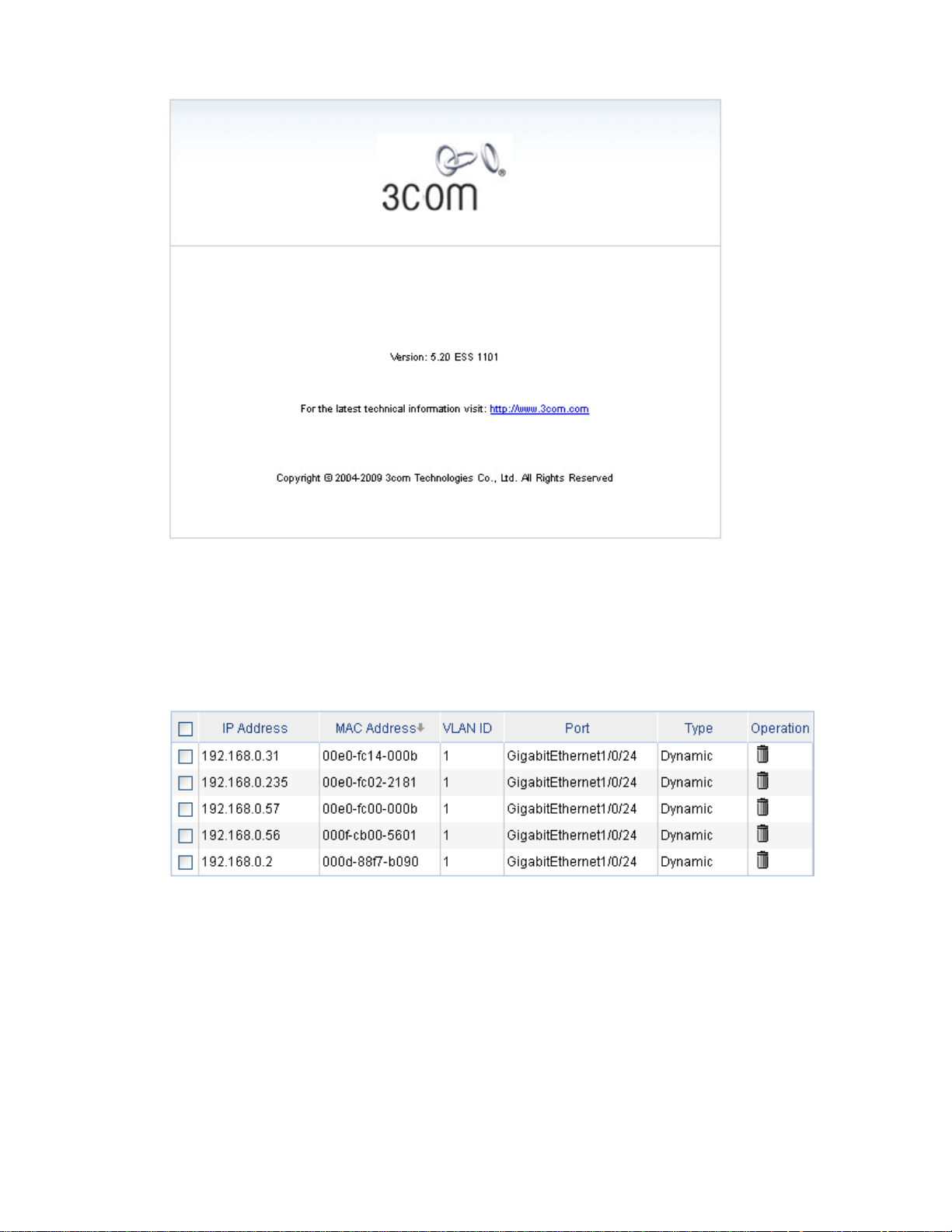
2-13
Figure 2-7 About
Sort display
On the page, you can click the blue items of each column to sort and display the records based on the
item you selected.
Figure 2-8 Sort display
Configuration Guidelines
z The Web-based console supports Microsoft Internet Explorer 6.0 SP2 and higher, but it does not
support the Back, Next, Refresh buttons provided by the browser. Using these buttons may result
in abnormal display of Web pages.
z When the device is performing spanning tree calculation, you cannot log in to or use the Web
interface.
z As the Windows firewall limits the number of TCP connections, when you use IE to log in to the
Web interface, sometimes you may be unable to open the Web interface. To avoid this problem, it
is recommended to turn off the Windows firewall before login.

2-14
z If the software version of the device changes, when you log in to the device through the Web
interface, you are recommended to delete the temporary Internet files of IE; otherwise, the Web
page content may not be displayed correctly.

3-1
3 Configuration Through the Command Line
Interface
z The 3Com baseline switch 2900 family can be configured through the command line interface (CLI),
web interface, and SNMP/MIB, among which the web interface supports all switch 2900 series
configurations. These configuration methods are suitable for different application scenarios. As a
supplementary to the web interface, the CLI provides some configuration commands to facilitate
your operation, which are described in this chapter. To perform other configurations not supported
by the CLI, use the web interface.
z You will enter user view directly after you log in to the device. Commands in the document are all
performed in user view.
Getting Started with the Command Line Interface
As a supplementary to the web interface, the CLI provides some configuration commands to facilitate
your operation. For example, if you forget the IP address of VLAN-interface 1 and cannot log in to the
device through the Web interface, you can connect the console port of the device to a PC, and
reconfigure the IP address of VLAN-interface 1 through the CLI.
This section describes using the CLI to manage the device.
Setting Up the Configuration Environment
Set up the configuration environment as follows:
Step1 Take the console cable out of the package. (A console cable is an 8-core shielded cable. One end of the
cable is a crimped RJ-45 connector, which is connected to the console port of the switch, and the other
end is a DB-9 female connector, which is connected to the serial port on the console terminal, as shown
below.)
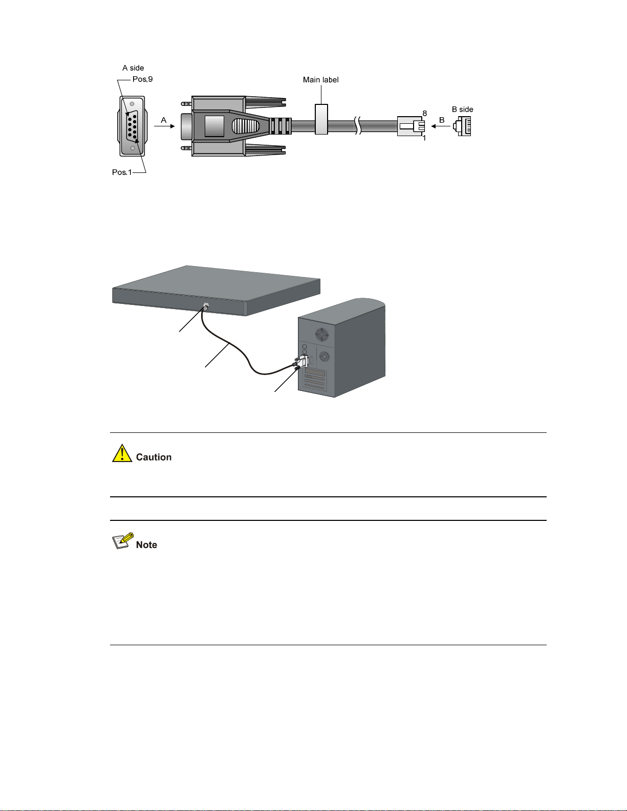
3-2
Figure 3-1 Console cable
Step2 Plug the DB-9 female connector of the console cable to the serial port of the console terminal or PC.
Step3 Connect the RJ-45 connector of the console cable to the console port of the switch. (as shown below)
Figure 3-2 Network diagram for configuration environment setup
Console port
Serial port
Console cable
Pay attention to the mark on the console port and be sure to plug the connector to the correct port.
z When connecting a PC to a powered-on switch, you are recommended to connect the DB-9
connector of the console cable to the PC before connecting the RJ-45 connector to the switch.
z When disconnecting a PC from a powered-on switch, you are recommended to disconnect the
DB-9 connector of the console cable from the PC after disconnecting the RJ-45 connector from the
switch.
Setting Terminal Parameters
When setting up the configuration environment through the console port, the terminal or PC can use the
terminal emulation program to communicate with the switch. You can run the HyperTerminal of the
Windows operating system to connect to other PCs, network devices, and Telnet sites. For detailed
3-3
information and the use of the HyperTerminal, refer to the HyperTerminal Help documentation in Help
and Support Center on the PC running the Windows operating system.
In the following configuration procedure, Windows XP HyperTerminal is used to communicate with the
switch.
1) Start the PC and run the terminal emulation program.
2) Set terminal parameters as follows:
z Bits per second: 38,400
z Data bits: 8
z Parity: None
z Stop bits: 1
z Flow control: None
z Emulation: VT100
The specific procedure is as follows:
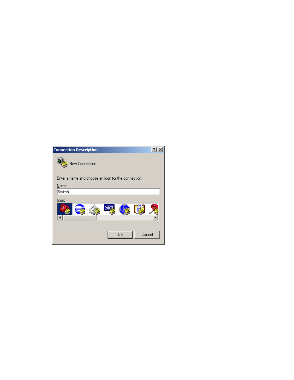
Step1 Select Start > Programs > Accessories > Communications > HyperTerminal to enter the
HyperTerminal window. The Connection Descriptio n dialog box appears, as shown below.
Figure 3-3 Connection description of the HyperTerminal
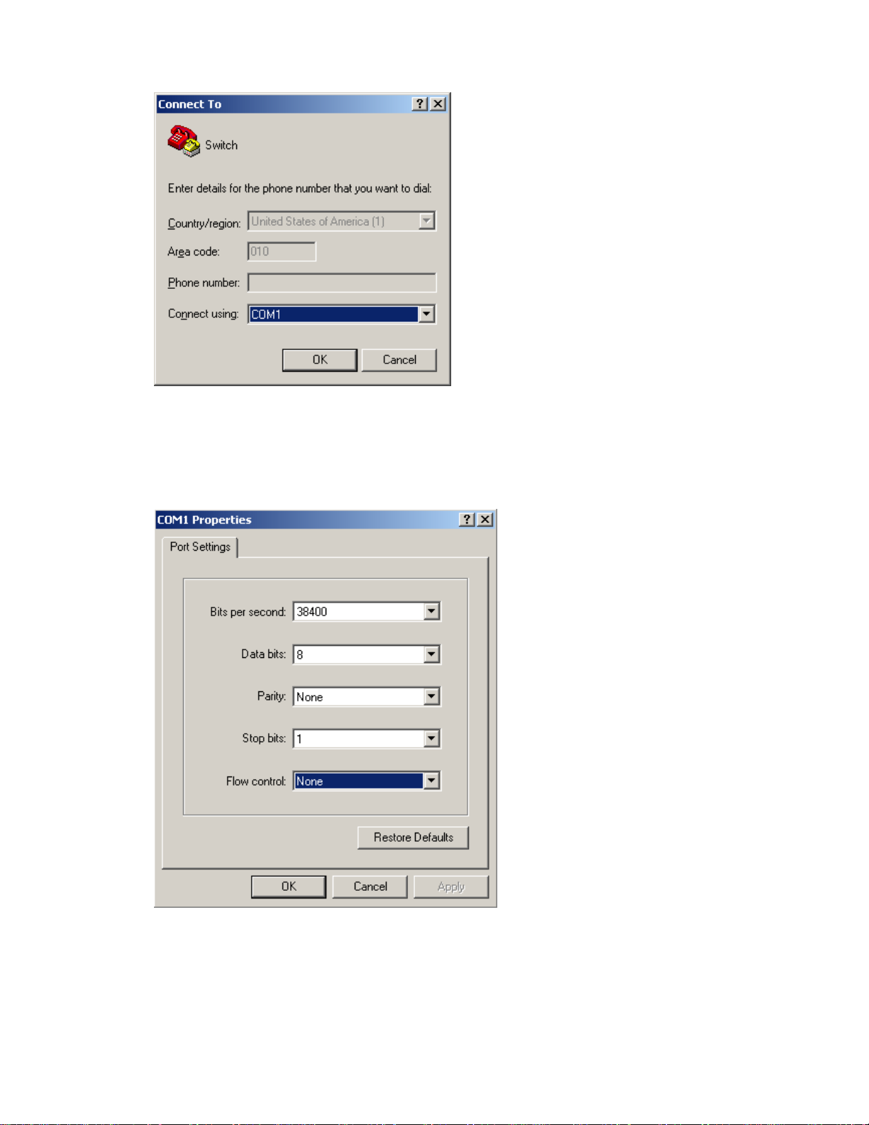
Step2 Type the name of the new connection in the Name text box and click OK. The following dialog box
appears. Select the serial port to be used from the Connect using drop-down list.
3-4
Figure 3-4 Set the serial port used by the HyperTerminal connection
Step3 Click OK after selecting a serial port. The following dialog box appears. Set Bits per second to 38400,
Data bits to 8, Parity to None, Stop bits to 1, and Flow control to None.
Figure 3-5 Set the serial port parameters
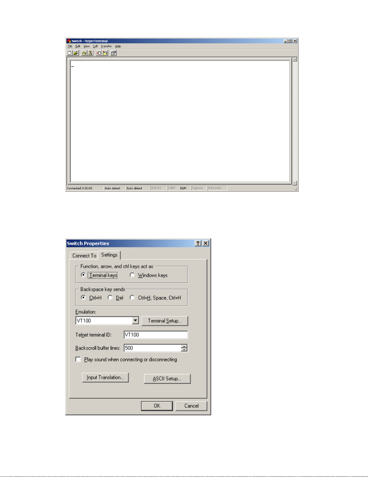
Step4 Click OK after setting the serial port parameters and the system enters the HyperTerminal window
shown below.
3-5
Figure 3-6 HyperTerminal window
Step5 Click Properties in the HyperTerminal window to enter the Switch Properties dialog box. Click the
Settings tab, set the emulation to VT100, and then click OK.
Figure 3-7 Set terminal emulation in Switch Properties dialog box

3-6
Logging In to the CLI
The login process requires a user name and password. The default user name for first time
configuration is admin, no password is required. User names and passwords are case sensitive.
To logon to the CLI Interface:
Step1 Press Enter. The Username prompt displays:
Login authentication
Username:
Step2 Enter your User Name at the Username prompt.
Username:admin
Step3 Press Enter. The Password prompt display
Password:
The login information is verified, and displays the following CLI menu:
<3Com Baseline Switch>
If the password is invalid, the following message appears and process restarts.
% Login failed!
CLI Commands
This Command section contains the following commands:
To do… Use the command…
Displays a list of CLI commands on the device
?
Reboot the device and run the default configuration
initialize
Specify VLAN-interface 1 to obtain an IP address
through DHCP or manual configuration
ipsetup { dhcp | ip address ip-address
{ mask | mask-length } [ default-gateway
ip-address ] }
Modify the login password of a user
password
Download the Boot ROM program or boot file from the
TFTP server and specify it to be used at the next startup
upgrade server-address source-filename
{ bootrom | runtime }
Reboot the device and run the main configuration file
reboot
View the summary information of the device
summary
Ping a specified destination
ping host
initialize
Syntax
initialize
Parameters
None

3-7
Description
Use the initialize command to delete the configuration file to be used at the next startup and reboot the
device with the default configuration being used during reboot.
Use the command with caution because this command deletes the configuration file to be used at the
next startup and restores the factory default settings.
Examples
# Delete the configuration file to be used at the next startup and reboot the device with the default
configuration being used during reboot.
<Sysname> initialize
The startup configuration file will be deleted and the system will be rebooted.Continue?
[Y/N]:y
Please wait...
ipsetup
Syntax
ipsetup { dhcp | ip address ip-address { mask | mask-length } [ default-gateway ip-address ] }
Parameters
dhcp: Specifies the interface to obtain an IP address through DHCP.
ip-address ip-address: Specifies an IP address for VLAN-interface 1 in dotted decimal notation.
mask: Subnet mask in dotted decimal notation.
mask-length: Subnet mask length, the number of consecutive ones in the mask, in the range of 0 to 32.
default-gateway ip-address: Specifies the IP address of the default gateway or the IP address of the
outbound interface. With this argument and keyword combination configured, the command not only
assigns an IP address to the interface, but also specifies a default route for the device.
Description
Use the ipsetup dhcp command to specify VLAN-interface 1 to obtain an IP address through DHCP.
Use the ipsetup ip address ip-address { mask | mask-length } command to assign an IP address to
VLAN-interface 1.
By default, the device automatically obtains its IP address through DHCP; if fails, it uses the assigned
default IP address. See
Figure 2-2
for details.
If there is no VLAN-interface 1, either command creates VLAN-interface 1 first, and then specifies its IP
address.
Examples
# Create VLAN-interface 1 and specify the interface to obtain an IP address through DHCP.
<Sysname> ipsetup dhcp
# Create VLAN-interface 1 and assign 192.168.1.2 to the interface, and specify 192.168.1.1 as the
default gateway.
<Sysname> ipsetup ip-address 192.168.1.2 24 default-gateway 192.168.1.1

3-8
password
Syntax
password
Parameters
None
Description
Use the password command to modify the login password of a user.
Examples
# Modify the login password of user admin.
<Sysname> password
Change password for user: admin
Old password: ***
Enter new password: **
Retype password: **
The password has been successfully changed.
ping
Syntax
ping host
Parameters
host: Destination IP address (in dotted decimal notation), URL, or host name (a string of 1 to 20
characters).
Description
Use the ping command to ping a specified destination.
You can enter Ctrl+C to terminate a ping operation.
Examples
# Ping IP address 1.1.2.2.
<Sysname> ping 1.1.2.2
PING 1.1.2.2: 56 data bytes, press CTRL_C to break
Reply from 1.1.2.2: bytes=56 Sequence=1 ttl=254 time=205 ms
Reply from 1.1.2.2: bytes=56 Sequence=2 ttl=254 time=1 ms
Reply from 1.1.2.2: bytes=56 Sequence=3 ttl=254 time=1 ms
Reply from 1.1.2.2: bytes=56 Sequence=4 ttl=254 time=1 ms
Reply from 1.1.2.2: bytes=56 Sequence=5 ttl=254 time=1 ms
--- 1.1.2.2 ping statistics ---
5 packet(s) transmitted
5 packet(s) received
0.00% packet loss
 Loading...