


PCI7621/PCI7611/PCI7421/PCI7411
Dual/Single Socket CardBus and UltraMedia Controller
With Integrated 1394a"2000 OHCI Two"Port
PHY/Link"Layer Controller With Dedicated Flash Media
Socket
Data Manual
June 2004 |
Connectivity Solutions |
SCPS081

IMPORTANT NOTICE
Texas Instruments Incorporated and its subsidiaries (TI) reserve the right to make corrections, modifications, enhancements, improvements, and other changes to its products and services at any time and to discontinue any product or service without notice. Customers should obtain the latest relevant information before placing orders and should verify that such information is current and complete. All products are sold subject to TI’s terms and conditions of sale supplied at the time of order acknowledgment.
TI warrants performance of its hardware products to the specifications applicable at the time of sale in accordance with TI’s standard warranty. Testing and other quality control techniques are used to the extent TI deems necessary to support this warranty. Except where mandated by government requirements, testing of all parameters of each product is not necessarily performed.
TI assumes no liability for applications assistance or customer product design. Customers are responsible for their products and applications using TI components. To minimize the risks associated with customer products and applications, customers should provide adequate design and operating safeguards.
TI does not warrant or represent that any license, either express or implied, is granted under any TI patent right, copyright, mask work right, or other TI intellectual property right relating to any combination, machine, or process in which TI products or services are used. Information published by TI regarding third-party products or services does not constitute a license from TI to use such products or services or a warranty or endorsement thereof. Use of such information may require a license from a third party under the patents or other intellectual property of the third party, or a license from TI under the patents or other intellectual property of TI.
Reproduction of information in TI data books or data sheets is permissible only if reproduction is without alteration and is accompanied by all associated warranties, conditions, limitations, and notices. Reproduction of this information with alteration is an unfair and deceptive business practice. TI is not responsible or liable for such altered documentation.
Resale of TI products or services with statements different from or beyond the parameters stated by TI for that product or service voids all express and any implied warranties for the associated TI product or service and is an unfair and deceptive business practice. TI is not responsible or liable for any such statements.
Following are URLs where you can obtain information on other Texas Instruments products and application solutions:
Products |
|
Applications |
|
Amplifiers |
amplifier.ti.com |
Audio |
www.ti.com/audio |
Data Converters |
dataconverter.ti.com |
Automotive |
www.ti.com/automotive |
DSP |
dsp.ti.com |
Broadband |
www.ti.com/broadband |
Interface |
interface.ti.com |
Digital Control |
www.ti.com/digitalcontrol |
Logic |
logic.ti.com |
Military |
www.ti.com/military |
Power Mgmt |
power.ti.com |
Optical Networking |
www.ti.com/opticalnetwork |
Microcontrollers |
microcontroller.ti.com |
Security |
www.ti.com/security |
|
|
Telephony |
www.ti.com/telephony |
|
|
Video & Imaging |
www.ti.com/video |
|
|
Wireless |
www.ti.com/wireless |
Mailing Address: |
Texas Instruments |
|
|
|
Post Office Box 655303 Dallas, Texas 75265 |
|
|
Copyright 2004, Texas Instruments Incorporated

Contents
Section |
Title |
Page |
1 Introduction . . . . . . . . . . . . . . . . . . . . |
. . . . . . . . . . . . . . . . . . . . . . . . . . . . . . . . . . |
1−1 |
1.1 Controller Functional Description . . . . . . . . . . . . . . . . . . . . . . . . . . . . . . 1−1
1.1.1 PCI7621 Controller . . . . . . . . . . . . . . . . . . . . . . . . . . . . . . . . . 1−1
1.1.2 PCI7421 Controller . . . . . . . . . . . . . . . . . . . . . . . . . . . . . . . . . 1−2
1.1.3 PCI7611 Controller . . . . . . . . . . . . . . . . . . . . . . . . . . . . . . . . . . 1−2
1.1.4 PCI7411 Controller . . . . . . . . . . . . . . . . . . . . . . . . . . . . . . . . . . 1−3
1.1.5 Multifunctional Terminals . . . . . . . . . . . . . . . . . . . . . . . . . . . . . 1−3
1.1.6 PCI Bus Power Management . . . . . . . . . . . . . . . . . . . . . . . . . 1−3
1.1.7 Power Switch Interface . . . . . . . . . . . . . . . . . . . . . . . . . . . . . . 1−3
1.2 Features . . . . . . . . . . . . . . . . . . . . . . . . . . . . . . . . . . . . . . . . . . . . . . . . . . . 1−4
1.3 Related Documents . . . . . . . . . . . . . . . . . . . . . . . . . . . . . . . . . . . . . . . . . . 1−5
1.4 Trademarks . . . . . . . . . . . . . . . . . . . . . . . . . . . . . . . . . . . . . . . . . . . . . . . . . 1−6
1.5 Terms and Definitions . . . . . . . . . . . . . . . . . . . . . . . . . . . . . . . . . . . . . . . . 1−7
1.6 Ordering Information . . . . . . . . . . . . . . . . . . . . . . . . . . . . . . . . . . . . . . . . . 1−7
2 |
Terminal Descriptions . . . . . . . . . . . . . . . . . . . . . . . . . . . . . . . . . . . . . . . . . . . . . |
2−1 |
|
|
2.1 |
Detailed Terminal Descriptions . . . . . . . . . . . . . . . . . . . . . . . . . . . . . . . . |
2−13 |
3 |
Feature/Protocol Descriptions . . . . . . . . . . . . . . . . . . . . . . . . . . . . . . . . . . . . . |
3−1 |
|
3.1 Power Supply Sequencing . . . . . . . . . . . . . . . . . . . . . . . . . . . . . . . . . . . . 3−1 3.2 I/O Characteristics . . . . . . . . . . . . . . . . . . . . . . . . . . . . . . . . . . . . . . . . . . . 3−2 3.3 Clamping Voltages . . . . . . . . . . . . . . . . . . . . . . . . . . . . . . . . . . . . . . . . . . . 3−2 3.4 Peripheral Component Interconnect (PCI) Interface . . . . . . . . . . . . . . 3−2 3.4.1 1394 PCI Bus Master . . . . . . . . . . . . . . . . . . . . . . . . . . . . . . . 3−2
3.4.2 Device Resets . . . . . . . . . . . . . . . . . . . . . . . . . . . . . . . . . . . . . . 3−3 3.4.3 Serial EEPROM I2C Bus . . . . . . . . . . . . . . . . . . . . . . . . . . . . . 3−3
3.4.4 Functions 0 and 1 (CardBus) Subsystem Identification . . . 3−4 3.4.5 Function 2 (OHCI 1394) Subsystem Identification . . . . . . . 3−5 3.4.6 Function 3 (Flash Media) Subsystem Identification . . . . . . 3−5 3.4.7 Function 4 (SD Host) Subsystem Identification . . . . . . . . . . 3−5 3.4.8 Function 5 (Smart Card) Subsystem Identification . . . . . . . 3−5
3.5 PC Card Applications . . . . . . . . . . . . . . . . . . . . . . . . . . . . . . . . . . . . . . . . 3−5 3.5.1 PC Card Insertion/Removal and Recognition . . . . . . . . . . . 3−6 3.5.2 Low Voltage CardBus Card Detection . . . . . . . . . . . . . . . . . 3−6 3.5.3 UltraMedia Card Detection . . . . . . . . . . . . . . . . . . . . . . . . . . . 3−6 3.5.4 Flash Media Card Detection . . . . . . . . . . . . . . . . . . . . . . . . . . 3−7 3.5.5 Power Switch Interface . . . . . . . . . . . . . . . . . . . . . . . . . . . . . . 3−8 3.5.6 Internal Ring Oscillator . . . . . . . . . . . . . . . . . . . . . . . . . . . . . . 3−8 3.5.7 Integrated Pullup Resistors for PC Card Interface . . . . . . . 3−9
iii

Section |
|
Title |
Page |
|
3.5.8 |
SPKROUT and CAUDPWM Usage . . . . . . . . . . . . . . . . . . . |
3−9 |
|
3.5.9 |
LED Socket Activity Indicators . . . . . . . . . . . . . . . . . . . . . . . . |
3−9 |
|
3.5.10 |
CardBus Socket Registers . . . . . . . . . . . . . . . . . . . . . . . . . . . |
3−10 |
|
3.5.11 |
48-MHz Clock Requirements . . . . . . . . . . . . . . . . . . . . . . . . . |
3−10 |
3.6 |
Serial EEPROM Interface . . . . . . . . . . . . . . . . . . . . . . . . . . . . . . . . . . . . . |
3−11 |
|
|
3.6.1 |
Serial-Bus Interface Implementation . . . . . . . . . . . . . . . . . . . |
3−11 |
|
3.6.2 |
Accessing Serial-Bus Devices Through Software . . . . . . . |
3−11 |
|
3.6.3 |
Serial-Bus Interface Protocol . . . . . . . . . . . . . . . . . . . . . . . . . |
3−11 |
|
3.6.4 |
Serial-Bus EEPROM Application . . . . . . . . . . . . . . . . . . . . . . |
3−13 |
3.7 |
Programmable Interrupt Subsystem . . . . . . . . . . . . . . . . . . . . . . . . . . . . |
3−16 |
|
3.7.1PC Card Functional and Card Status Change Interrupts . 3−17
3.7.2 Interrupt Masks and Flags . . . . . . . . . . . . . . . . . . . . . . . . . . . 3−18 3.7.3 Using Parallel IRQ Interrupts . . . . . . . . . . . . . . . . . . . . . . . . . 3−19 3.7.4 Using Parallel PCI Interrupts . . . . . . . . . . . . . . . . . . . . . . . . . 3−19 3.7.5 Using Serialized IRQSER Interrupts . . . . . . . . . . . . . . . . . . . 3−20 3.7.6 SMI Support in the PCI7x21/PCI7x11 Controller . . . . . . . . 3−20
3.8 Power Management Overview . . . . . . . . . . . . . . . . . . . . . . . . . . . . . . . . 3−20 3.8.1 1394 Power Management (Function 2) . . . . . . . . . . . . . . . . 3−21 3.8.2 Integrated Low-Dropout Voltage Regulator (LDO-VR) . . . . 3−22 3.8.3 CardBus (Functions 0 and 1) Clock Run Protocol . . . . . . . 3−22 3.8.4 CardBus PC Card Power Management . . . . . . . . . . . . . . . . 3−22 3.8.5 16-Bit PC Card Power Management . . . . . . . . . . . . . . . . . . . 3−23 3.8.6 Suspend Mode . . . . . . . . . . . . . . . . . . . . . . . . . . . . . . . . . . . . . 3−23 3.8.7 Requirements for Suspend Mode . . . . . . . . . . . . . . . . . . . . . 3−23 3.8.8 Ring Indicate . . . . . . . . . . . . . . . . . . . . . . . . . . . . . . . . . . . . . . . 3−24 3.8.9 PCI Power Management . . . . . . . . . . . . . . . . . . . . . . . . . . . . . 3−25
3.8.9.1CardBus Power Management
(Functions 0 and 1) . . . . . . . . . . . . . . . . . . . . . . 3−25
3.8.9.2OHCI 1394 (Function 2)
Power Management . . . . . . . . . . . . . . . . . . . . . . 3−26
3.8.9.3Flash Media (Function 3)
Power Management . . . . . . . . . . . . . . . . . . . . . . 3−26
3.8.9.4SD Host (Function 4)
Power Management . . . . . . . . . . . . . . . . . . . . . . 3−26
|
3.8.9.5 |
Smart Card (Function 5) |
|
|
|
Power Management . . . . . . . . . . . . . . . . . . . . . . |
3−26 |
3.8.10 |
CardBus Bridge Power Management . . . . . . . . . . . . . . . . . . |
3−26 |
|
3.8.11 |
ACPI Support . . . . . . . . . . . . . . . . . . . . . . . . . . . . . . . . . . . . . . |
3−27 |
|
3.8.12Master List of PME Context Bits and Global Reset-Only
Bits . . . . . . . . . . . . . . . . . . . . . . . . . . . . . . . . . . . . . . . . . . . . . . . 3−27
3.9 IEEE 1394 Application Information . . . . . . . . . . . . . . . . . . . . . . . . . . . . . 3−30
3.9.1 PHY Port Cable Connection . . . . . . . . . . . . . . . . . . . . . . . . . . 3−30
3.9.2 Crystal Selection . . . . . . . . . . . . . . . . . . . . . . . . . . . . . . . . . . . 3−31
3.9.3 Bus Reset . . . . . . . . . . . . . . . . . . . . . . . . . . . . . . . . . . . . . . . . . 3−32
iv

Section |
Title |
Page |
4 PC Card Controller Programming Model . . . . . . . . . . . . . . . . . . . . . . . . . . . . 4−1
4.1 PCI Configuration Register Map (Functions 0 and 1) . . . . . . . . . . . . . 4−1 4.2 Vendor ID Register . . . . . . . . . . . . . . . . . . . . . . . . . . . . . . . . . . . . . . . . . . 4−2 4.3 Device ID Register Functions 0 and 1 . . . . . . . . . . . . . . . . . . . . . . . . . . 4−3 4.4 Command Register . . . . . . . . . . . . . . . . . . . . . . . . . . . . . . . . . . . . . . . . . . 4−4 4.5 Status Register . . . . . . . . . . . . . . . . . . . . . . . . . . . . . . . . . . . . . . . . . . . . . . 4−5 4.6 Revision ID Register . . . . . . . . . . . . . . . . . . . . . . . . . . . . . . . . . . . . . . . . . 4−6 4.7 Class Code Register . . . . . . . . . . . . . . . . . . . . . . . . . . . . . . . . . . . . . . . . . 4−6 4.8 Cache Line Size Register . . . . . . . . . . . . . . . . . . . . . . . . . . . . . . . . . . . . . 4−6 4.9 Latency Timer Register . . . . . . . . . . . . . . . . . . . . . . . . . . . . . . . . . . . . . . . 4−7 4.10 Header Type Register . . . . . . . . . . . . . . . . . . . . . . . . . . . . . . . . . . . . . . . . 4−7 4.11 BIST Register . . . . . . . . . . . . . . . . . . . . . . . . . . . . . . . . . . . . . . . . . . . . . . . 4−7 4.12 CardBus Socket Registers/ExCA Base Address Register . . . . . . . . . 4−8 4.13 Capability Pointer Register . . . . . . . . . . . . . . . . . . . . . . . . . . . . . . . . . . . . 4−8 4.14 Secondary Status Register . . . . . . . . . . . . . . . . . . . . . . . . . . . . . . . . . . . 4−9 4.15 PCI Bus Number Register . . . . . . . . . . . . . . . . . . . . . . . . . . . . . . . . . . . . 4−10 4.16 CardBus Bus Number Register . . . . . . . . . . . . . . . . . . . . . . . . . . . . . . . . 4−10 4.17 Subordinate Bus Number Register . . . . . . . . . . . . . . . . . . . . . . . . . . . . . 4−10 4.18 CardBus Latency Timer Register . . . . . . . . . . . . . . . . . . . . . . . . . . . . . . 4−11 4.19 CardBus Memory Base Registers 0, 1 . . . . . . . . . . . . . . . . . . . . . . . . . . 4−11 4.20 CardBus Memory Limit Registers 0, 1 . . . . . . . . . . . . . . . . . . . . . . . . . . 4−12 4.21 CardBus I/O Base Registers 0, 1 . . . . . . . . . . . . . . . . . . . . . . . . . . . . . . 4−12 4.22 CardBus I/O Limit Registers 0, 1 . . . . . . . . . . . . . . . . . . . . . . . . . . . . . . 4−13 4.23 Interrupt Line Register . . . . . . . . . . . . . . . . . . . . . . . . . . . . . . . . . . . . . . . 4−13 4.24 Interrupt Pin Register . . . . . . . . . . . . . . . . . . . . . . . . . . . . . . . . . . . . . . . . 4−14 4.25 Bridge Control Register . . . . . . . . . . . . . . . . . . . . . . . . . . . . . . . . . . . . . . 4−15 4.26 Subsystem Vendor ID Register . . . . . . . . . . . . . . . . . . . . . . . . . . . . . . . . 4−16 4.27 Subsystem ID Register . . . . . . . . . . . . . . . . . . . . . . . . . . . . . . . . . . . . . . . 4−17 4.28 PC Card 16-Bit I/F Legacy-Mode Base-Address Register . . . . . . . . . 4−17 4.29 System Control Register . . . . . . . . . . . . . . . . . . . . . . . . . . . . . . . . . . . . . . 4−18 4.30 MC_CD Debounce Register . . . . . . . . . . . . . . . . . . . . . . . . . . . . . . . . . . 4−20 4.31 General Control Register . . . . . . . . . . . . . . . . . . . . . . . . . . . . . . . . . . . . . 4−21 4.32 General-Purpose Event Status Register . . . . . . . . . . . . . . . . . . . . . . . . 4−23 4.33 General-Purpose Event Enable Register . . . . . . . . . . . . . . . . . . . . . . . 4−24 4.34 General-Purpose Input Register . . . . . . . . . . . . . . . . . . . . . . . . . . . . . . . 4−24 4.35 General-Purpose Output Register . . . . . . . . . . . . . . . . . . . . . . . . . . . . . 4−25 4.36 Multifunction Routing Status Register . . . . . . . . . . . . . . . . . . . . . . . . . . 4−26 4.37 Retry Status Register . . . . . . . . . . . . . . . . . . . . . . . . . . . . . . . . . . . . . . . . 4−27 4.38 Card Control Register . . . . . . . . . . . . . . . . . . . . . . . . . . . . . . . . . . . . . . . . 4−28 4.39 Device Control Register . . . . . . . . . . . . . . . . . . . . . . . . . . . . . . . . . . . . . . 4−29 4.40 Diagnostic Register . . . . . . . . . . . . . . . . . . . . . . . . . . . . . . . . . . . . . . . . . . 4−30 4.41 Capability ID Register . . . . . . . . . . . . . . . . . . . . . . . . . . . . . . . . . . . . . . . . 4−31
v

Section |
Title |
Page |
4.42 |
Next Item Pointer Register . . . . . . . . . . . . . . . . . . . . . . . . . . . . . . . . . . . . |
4−31 |
4.43 |
Power Management Capabilities Register . . . . . . . . . . . . . . . . . . . . . . |
4−32 |
4.44 |
Power Management Control/Status Register . . . . . . . . . . . . . . . . . . . . |
4−33 |
4.45Power Management Control/Status Bridge Support Extensions
Register . . . . . . . . . . . . . . . . . . . . . . . . . . . . . . . . . . . . . . . . . . . . . . . . . . . . 4−34 4.46 Power-Management Data Register . . . . . . . . . . . . . . . . . . . . . . . . . . . . 4−34 4.47 Serial Bus Data Register . . . . . . . . . . . . . . . . . . . . . . . . . . . . . . . . . . . . . 4−35 4.48 Serial Bus Index Register . . . . . . . . . . . . . . . . . . . . . . . . . . . . . . . . . . . . . 4−35 4.49 Serial Bus Slave Address Register . . . . . . . . . . . . . . . . . . . . . . . . . . . . . 4−36 4.50 Serial Bus Control/Status Register . . . . . . . . . . . . . . . . . . . . . . . . . . . . . 4−37
5 ExCA Compatibility Registers (Functions 0 and 1) . . . . . . . . . . . . . . . . . . 5−1
5.1 ExCA Identification and Revision Register . . . . . . . . . . . . . . . . . . . . . . 5−5 5.2 ExCA Interface Status Register . . . . . . . . . . . . . . . . . . . . . . . . . . . . . . . . 5−6 5.3 ExCA Power Control Register . . . . . . . . . . . . . . . . . . . . . . . . . . . . . . . . . 5−7 5.4 ExCA Interrupt and General Control Register . . . . . . . . . . . . . . . . . . . 5−8 5.5 ExCA Card Status-Change Register . . . . . . . . . . . . . . . . . . . . . . . . . . . 5−9 5.6 ExCA Card Status-Change Interrupt Configuration Register . . . . . . . 5−10 5.7 ExCA Address Window Enable Register . . . . . . . . . . . . . . . . . . . . . . . . 5−11 5.8 ExCA I/O Window Control Register . . . . . . . . . . . . . . . . . . . . . . . . . . . . 5−12
5.9ExCA I/O Windows 0 and 1 Start-Address Low-Byte Registers . . . . 5−13
5.10 ExCA I/O Windows 0 and 1 Start-Address High-Byte Registers . . . . 5−13
5.11ExCA I/O Windows 0 and 1 End-Address Low-Byte Registers . . . . . 5−14
5.12ExCA I/O Windows 0 and 1 End-Address High-Byte Registers . . . . 5−14
5.13 ExCA Memory Windows 0−4 Start-Address Low-Byte Registers . . . 5−15
5.14ExCA Memory Windows 0−4 Start-Address High-Byte Registers . . . 5−16
5.15ExCA Memory Windows 0−4 End-Address Low-Byte Registers . . . . 5−17
5.16 ExCA Memory Windows 0−4 End-Address High-Byte Registers . . . 5−18
5.17ExCA Memory Windows 0−4 Offset-Address Low-Byte Registers . . 5−19
5.18 |
ExCA Memory Windows 0−4 Offset-Address High-Byte Registers |
. 5−20 |
5.19 |
ExCA Card Detect and General Control Register . . . . . . . . . . . . . . . |
. 5−21 |
5.20 |
ExCA Global Control Register . . . . . . . . . . . . . . . . . . . . . . . . . . . . . . . . |
. 5−22 |
5.21ExCA I/O Windows 0 and 1 Offset-Address Low-Byte Registers . . . 5−23
5.22 |
ExCA I/O Windows 0 and 1 Offset-Address High-Byte Registers . . . |
5−23 |
5.23 |
ExCA Memory Windows 0−4 Page Registers . . . . . . . . . . . . . . . . . . . |
5−24 |
6 CardBus Socket Registers (Functions 0 and 1) . . . . . . . . . . . . . . . . . . . . . . |
6−1 |
|
6.1 Socket Event Register . . . . . . . . . . . . . . . . . . . . . . . . . . . . . . . . . . . . . . . 6−2 6.2 Socket Mask Register . . . . . . . . . . . . . . . . . . . . . . . . . . . . . . . . . . . . . . . . 6−3 6.3 Socket Present State Register . . . . . . . . . . . . . . . . . . . . . . . . . . . . . . . . 6−4 6.4 Socket Force Event Register . . . . . . . . . . . . . . . . . . . . . . . . . . . . . . . . . . 6−5 6.5 Socket Control Register . . . . . . . . . . . . . . . . . . . . . . . . . . . . . . . . . . . . . . 6−7 6.6 Socket Power Management Register . . . . . . . . . . . . . . . . . . . . . . . . . . . 6−8
vi

Section |
Title |
Page |
7 OHCI Controller Programming Model . . . . . . . . . . . . . . . . . . . . . . . . . . . . . . . 7−1
7.1 Vendor ID Register . . . . . . . . . . . . . . . . . . . . . . . . . . . . . . . . . . . . . . . . . . 7−2 7.2 Device ID Register . . . . . . . . . . . . . . . . . . . . . . . . . . . . . . . . . . . . . . . . . . . 7−2 7.3 Command Register . . . . . . . . . . . . . . . . . . . . . . . . . . . . . . . . . . . . . . . . . . 7−3 7.4 Status Register . . . . . . . . . . . . . . . . . . . . . . . . . . . . . . . . . . . . . . . . . . . . . . 7−4 7.5 Class Code and Revision ID Register . . . . . . . . . . . . . . . . . . . . . . . . . . 7−5 7.6 Latency Timer and Class Cache Line Size Register . . . . . . . . . . . . . . 7−5 7.7 Header Type and BIST Register . . . . . . . . . . . . . . . . . . . . . . . . . . . . . . . 7−6 7.8 OHCI Base Address Register . . . . . . . . . . . . . . . . . . . . . . . . . . . . . . . . . 7−6 7.9 TI Extension Base Address Register . . . . . . . . . . . . . . . . . . . . . . . . . . . 7−7 7.10 CardBus CIS Base Address Register . . . . . . . . . . . . . . . . . . . . . . . . . . . 7−8 7.11 CardBus CIS Pointer Register . . . . . . . . . . . . . . . . . . . . . . . . . . . . . . . . . 7−8 7.12 Subsystem Identification Register . . . . . . . . . . . . . . . . . . . . . . . . . . . . . 7−9 7.13 Power Management Capabilities Pointer Register . . . . . . . . . . . . . . . 7−9 7.14 Interrupt Line Register . . . . . . . . . . . . . . . . . . . . . . . . . . . . . . . . . . . . . . . 7−10 7.15 Interrupt Pin Register . . . . . . . . . . . . . . . . . . . . . . . . . . . . . . . . . . . . . . . . 7−10 7.16 Minimum Grant and Maximum Latency Register . . . . . . . . . . . . . . . . . 7−11 7.17 OHCI Control Register . . . . . . . . . . . . . . . . . . . . . . . . . . . . . . . . . . . . . . . 7−11 7.18 Capability ID and Next Item Pointer Registers . . . . . . . . . . . . . . . . . . . 7−12 7.19 Power Management Capabilities Register . . . . . . . . . . . . . . . . . . . . . . 7−13 7.20 Power Management Control and Status Register . . . . . . . . . . . . . . . . 7−14 7.21 Power Management Extension Registers . . . . . . . . . . . . . . . . . . . . . . . 7−14 7.22 PCI PHY Control Register . . . . . . . . . . . . . . . . . . . . . . . . . . . . . . . . . . . . 7−15 7.23 PCI Miscellaneous Configuration Register . . . . . . . . . . . . . . . . . . . . . . 7−16 7.24 Link Enhancement Control Register . . . . . . . . . . . . . . . . . . . . . . . . . . . . 7−17 7.25 Subsystem Access Register . . . . . . . . . . . . . . . . . . . . . . . . . . . . . . . . . . 7−18 7.26 GPIO Control Register . . . . . . . . . . . . . . . . . . . . . . . . . . . . . . . . . . . . . . . 7−19
8 OHCI Registers . . . . . . . . . . . . . . . . . . . . . . . . . . . . . . . . . . . . . . . . . . . . . . . . . . . |
8−1 |
8.1 OHCI Version Register . . . . . . . . . . . . . . . . . . . . . . . . . . . . . . . . . . . . . . . 8−4 8.2 GUID ROM Register . . . . . . . . . . . . . . . . . . . . . . . . . . . . . . . . . . . . . . . . . 8−5 8.3 Asynchronous Transmit Retries Register . . . . . . . . . . . . . . . . . . . . . . . 8−6 8.4 CSR Data Register . . . . . . . . . . . . . . . . . . . . . . . . . . . . . . . . . . . . . . . . . . 8−6 8.5 CSR Compare Register . . . . . . . . . . . . . . . . . . . . . . . . . . . . . . . . . . . . . . 8−7 8.6 CSR Control Register . . . . . . . . . . . . . . . . . . . . . . . . . . . . . . . . . . . . . . . . 8−7 8.7 Configuration ROM Header Register . . . . . . . . . . . . . . . . . . . . . . . . . . . 8−8 8.8 Bus Identification Register . . . . . . . . . . . . . . . . . . . . . . . . . . . . . . . . . . . . 8−8 8.9 Bus Options Register . . . . . . . . . . . . . . . . . . . . . . . . . . . . . . . . . . . . . . . . 8−9 8.10 GUID High Register . . . . . . . . . . . . . . . . . . . . . . . . . . . . . . . . . . . . . . . . . . 8−10 8.11 GUID Low Register . . . . . . . . . . . . . . . . . . . . . . . . . . . . . . . . . . . . . . . . . . 8−10 8.12 Configuration ROM Mapping Register . . . . . . . . . . . . . . . . . . . . . . . . . . 8−11 8.13 Posted Write Address Low Register . . . . . . . . . . . . . . . . . . . . . . . . . . . . 8−11 8.14 Posted Write Address High Register . . . . . . . . . . . . . . . . . . . . . . . . . . . 8−12
vii

Section |
Title |
Page |
8.15 Vendor ID Register . . . . . . . . . . . . . . . . . . . . . . . . . . . . . . . . . . . . . . . . . . 8−12 8.16 Host Controller Control Register . . . . . . . . . . . . . . . . . . . . . . . . . . . . . . . 8−13 8.17 Self-ID Buffer Pointer Register . . . . . . . . . . . . . . . . . . . . . . . . . . . . . . . . 8−14 8.18 Self-ID Count Register . . . . . . . . . . . . . . . . . . . . . . . . . . . . . . . . . . . . . . . 8−15 8.19 Isochronous Receive Channel Mask High Register . . . . . . . . . . . . . . 8−16 8.20 Isochronous Receive Channel Mask Low Register . . . . . . . . . . . . . . . 8−17 8.21 Interrupt Event Register . . . . . . . . . . . . . . . . . . . . . . . . . . . . . . . . . . . . . . 8−18 8.22 Interrupt Mask Register . . . . . . . . . . . . . . . . . . . . . . . . . . . . . . . . . . . . . . 8−20 8.23 Isochronous Transmit Interrupt Event Register . . . . . . . . . . . . . . . . . . 8−22 8.24 Isochronous Transmit Interrupt Mask Register . . . . . . . . . . . . . . . . . . . 8−23 8.25 Isochronous Receive Interrupt Event Register . . . . . . . . . . . . . . . . . . . 8−24 8.26 Isochronous Receive Interrupt Mask Register . . . . . . . . . . . . . . . . . . . 8−25 8.27 Initial Bandwidth Available Register . . . . . . . . . . . . . . . . . . . . . . . . . . . . 8−25 8.28 Initial Channels Available High Register . . . . . . . . . . . . . . . . . . . . . . . . 8−26 8.29 Initial Channels Available Low Register . . . . . . . . . . . . . . . . . . . . . . . . . 8−26 8.30 Fairness Control Register . . . . . . . . . . . . . . . . . . . . . . . . . . . . . . . . . . . . 8−27 8.31 Link Control Register . . . . . . . . . . . . . . . . . . . . . . . . . . . . . . . . . . . . . . . . . 8−28 8.32 Node Identification Register . . . . . . . . . . . . . . . . . . . . . . . . . . . . . . . . . . . 8−29 8.33 PHY Layer Control Register . . . . . . . . . . . . . . . . . . . . . . . . . . . . . . . . . . . 8−30 8.34 Isochronous Cycle Timer Register . . . . . . . . . . . . . . . . . . . . . . . . . . . . . 8−31 8.35 Asynchronous Request Filter High Register . . . . . . . . . . . . . . . . . . . . . 8−32 8.36 Asynchronous Request Filter Low Register . . . . . . . . . . . . . . . . . . . . . 8−34 8.37 Physical Request Filter High Register . . . . . . . . . . . . . . . . . . . . . . . . . . 8−35 8.38 Physical Request Filter Low Register . . . . . . . . . . . . . . . . . . . . . . . . . . 8−37 8.39 Physical Upper Bound Register (Optional Register) . . . . . . . . . . . . . . 8−37 8.40 Asynchronous Context Control Register . . . . . . . . . . . . . . . . . . . . . . . . 8−38 8.41 Asynchronous Context Command Pointer Register . . . . . . . . . . . . . . 8−39 8.42 Isochronous Transmit Context Control Register . . . . . . . . . . . . . . . . . . 8−40 8.43 Isochronous Transmit Context Command Pointer Register . . . . . . . . 8−41 8.44 Isochronous Receive Context Control Register . . . . . . . . . . . . . . . . . . 8−41 8.45 Isochronous Receive Context Command Pointer Register . . . . . . . . 8−43 8.46 Isochronous Receive Context Match Register . . . . . . . . . . . . . . . . . . . 8−44
9 TI Extension Registers . . . . . . . . . . . . . . . . . . . . . . . . . . . . . . . . . . . . . . . . . . . . |
9−1 |
|
9.1 |
DV and MPEG2 Timestamp Enhancements . . . . . . . . . . . . . . . . . . . . . |
9−1 |
9.2 |
Isochronous Receive Digital Video Enhancements . . . . . . . . . . . . . . . |
9−2 |
9.3 |
Isochronous Receive Digital Video Enhancements Register . . . . . . . |
9−2 |
9.4 |
Link Enhancement Register . . . . . . . . . . . . . . . . . . . . . . . . . . . . . . . . . . . |
9−4 |
9.5 |
Timestamp Offset Register . . . . . . . . . . . . . . . . . . . . . . . . . . . . . . . . . . . |
9−5 |
10 PHY Register Configuration . . . . . . . . . . . . . . . . . . . . . . . . . . . . . . . . . . . . . . . |
10−1 |
|
10.1 Base Registers . . . . . . . . . . . . . . . . . . . . . . . . . . . . . . . . . . . . . . . . . . . . . . 10−1 10.2 Port Status Register . . . . . . . . . . . . . . . . . . . . . . . . . . . . . . . . . . . . . . . . . 10−4 10.3 Vendor Identification Register . . . . . . . . . . . . . . . . . . . . . . . . . . . . . . . . . 10−5
viii

Section |
Title |
Page |
10.4 |
Vendor-Dependent Register . . . . . . . . . . . . . . . . . . . . . . . . . . . . . . . . . . |
10−6 |
10.5 |
Power-Class Programming . . . . . . . . . . . . . . . . . . . . . . . . . . . . . . . . . . . |
10−7 |
11 Flash Media Controller Programming Model . . . . . . . . . . . . . . . . . . . . . . . . |
11−1 |
|
11.1 Vendor ID Register . . . . . . . . . . . . . . . . . . . . . . . . . . . . . . . . . . . . . . . . . . 11−2 11.2 Device ID Register . . . . . . . . . . . . . . . . . . . . . . . . . . . . . . . . . . . . . . . . . . . 11−2 11.3 Command Register . . . . . . . . . . . . . . . . . . . . . . . . . . . . . . . . . . . . . . . . . . 11−3 11.4 Status Register . . . . . . . . . . . . . . . . . . . . . . . . . . . . . . . . . . . . . . . . . . . . . . 11−4 11.5 Class Code and Revision ID Register . . . . . . . . . . . . . . . . . . . . . . . . . . 11−5 11.6 Latency Timer and Class Cache Line Size Register . . . . . . . . . . . . . . 11−5 11.7 Header Type and BIST Register . . . . . . . . . . . . . . . . . . . . . . . . . . . . . . . 11−6 11.8 Flash Media Base Address Register . . . . . . . . . . . . . . . . . . . . . . . . . . . 11−6 11.9 Subsystem Vendor Identification Register . . . . . . . . . . . . . . . . . . . . . . . 11−7 11.10 Subsystem Identification Register . . . . . . . . . . . . . . . . . . . . . . . . . . . . . 11−7 11.11 Capabilities Pointer Register . . . . . . . . . . . . . . . . . . . . . . . . . . . . . . . . . . 11−7 11.12 Interrupt Line Register . . . . . . . . . . . . . . . . . . . . . . . . . . . . . . . . . . . . . . . 11−8 11.13 Interrupt Pin Register . . . . . . . . . . . . . . . . . . . . . . . . . . . . . . . . . . . . . . . . 11−8 11.14 Minimum Grant Register . . . . . . . . . . . . . . . . . . . . . . . . . . . . . . . . . . . . . 11−9 11.15 Maximum Latency Register . . . . . . . . . . . . . . . . . . . . . . . . . . . . . . . . . . . 11−9 11.16 Capability ID and Next Item Pointer Registers . . . . . . . . . . . . . . . . . 11−10 11.17 Power Management Capabilities Register . . . . . . . . . . . . . . . . . . . . 11−11 11.18 Power Management Control and Status Register . . . . . . . . . . . . . . 11−12 11.19 Power Management Bridge Support Extension Register . . . . . . . . 11−12 11.20 Power Management Data Register . . . . . . . . . . . . . . . . . . . . . . . . . . 11−13 11.21 General Control Register . . . . . . . . . . . . . . . . . . . . . . . . . . . . . . . . . . . 11−13 11.22 Subsystem Access Register . . . . . . . . . . . . . . . . . . . . . . . . . . . . . . . . 11−14 11.23 Diagnostic Register . . . . . . . . . . . . . . . . . . . . . . . . . . . . . . . . . . . . . . . . 11−15
12 SD Host Controller Programming Model . . . . . . . . . . . . . . . . . . . . . . . . . . . . 12−1
12.1 Vendor ID Register . . . . . . . . . . . . . . . . . . . . . . . . . . . . . . . . . . . . . . . . . . 12−2 12.2 Device ID Register . . . . . . . . . . . . . . . . . . . . . . . . . . . . . . . . . . . . . . . . . . . 12−2 12.3 Command Register . . . . . . . . . . . . . . . . . . . . . . . . . . . . . . . . . . . . . . . . . . 12−3 12.4 Status Register . . . . . . . . . . . . . . . . . . . . . . . . . . . . . . . . . . . . . . . . . . . . . . 12−4 12.5 Class Code and Revision ID Register . . . . . . . . . . . . . . . . . . . . . . . . . . 12−5 12.6 Latency Timer and Class Cache Line Size Register . . . . . . . . . . . . . . 12−6 12.7 Header Type and BIST Register . . . . . . . . . . . . . . . . . . . . . . . . . . . . . . . 12−6 12.8 SD Host Base Address Register . . . . . . . . . . . . . . . . . . . . . . . . . . . . . . . 12−7 12.9 Subsystem Vendor Identification Register . . . . . . . . . . . . . . . . . . . . . . . 12−7 12.10 Subsystem Identification Register . . . . . . . . . . . . . . . . . . . . . . . . . . . . . 12−8 12.11 Capabilities Pointer Register . . . . . . . . . . . . . . . . . . . . . . . . . . . . . . . . . . 12−8 12.12 Interrupt Line Register . . . . . . . . . . . . . . . . . . . . . . . . . . . . . . . . . . . . . . . 12−8 12.13 Interrupt Pin Register . . . . . . . . . . . . . . . . . . . . . . . . . . . . . . . . . . . . . . . . 12−9 12.14 Minimum Grant Register . . . . . . . . . . . . . . . . . . . . . . . . . . . . . . . . . . . . . 12−9 12.15 Maximum Latency Register . . . . . . . . . . . . . . . . . . . . . . . . . . . . . . . . . 12−10
ix

Section |
Title |
Page |
12.16 Slot Information Register . . . . . . . . . . . . . . . . . . . . . . . . . . . . . . . . . . . 12−10 12.17 Capability ID and Next Item Pointer Registers . . . . . . . . . . . . . . . . . 12−11 12.18 Power Management Capabilities Register . . . . . . . . . . . . . . . . . . . . 12−12 12.19 Power Management Control and Status Register . . . . . . . . . . . . . . 12−13 12.20 Power Management Bridge Support Extension Register . . . . . . . . 12−13 12.21 Power Management Data Register . . . . . . . . . . . . . . . . . . . . . . . . . . 12−14 12.22 General Control Register . . . . . . . . . . . . . . . . . . . . . . . . . . . . . . . . . . . 12−14 12.23 Subsystem Access Register . . . . . . . . . . . . . . . . . . . . . . . . . . . . . . . . 12−15 12.24 Diagnostic Register . . . . . . . . . . . . . . . . . . . . . . . . . . . . . . . . . . . . . . . . 12−15 12.25 Slot 0 3.3-V Maximum Current Register . . . . . . . . . . . . . . . . . . . . . . 12−16 12.26 Slot 1 3.3-V Maximum Current Register . . . . . . . . . . . . . . . . . . . . . . 12−16 12.27 Slot 2 3.3-V Maximum Current Register . . . . . . . . . . . . . . . . . . . . . . 12−16 12.28 Slot 3 3.3-V Maximum Current Register . . . . . . . . . . . . . . . . . . . . . . 12−17 12.29 Slot 4 3.3-V Maximum Current Register . . . . . . . . . . . . . . . . . . . . . . 12−17 12.30 Slot 5 3.3-V Maximum Current Register . . . . . . . . . . . . . . . . . . . . . . 12−17
13 Smart Card Controller Programming Model . . . . . . . . . . . . . . . . . . . . . . . . . 13−1
13.1 Vendor ID Register . . . . . . . . . . . . . . . . . . . . . . . . . . . . . . . . . . . . . . . . . . 13−2 13.2 Device ID Register . . . . . . . . . . . . . . . . . . . . . . . . . . . . . . . . . . . . . . . . . . . 13−2 13.3 Command Register . . . . . . . . . . . . . . . . . . . . . . . . . . . . . . . . . . . . . . . . . . 13−3 13.4 Status Register . . . . . . . . . . . . . . . . . . . . . . . . . . . . . . . . . . . . . . . . . . . . . . 13−4 13.5 Class Code and Revision ID Register . . . . . . . . . . . . . . . . . . . . . . . . . . 13−5 13.6 Latency Timer and Class Cache Line Size Register . . . . . . . . . . . . . . 13−5 13.7 Header Type and BIST Register . . . . . . . . . . . . . . . . . . . . . . . . . . . . . . . 13−6 13.8 Smart Card Base Address Register 0 . . . . . . . . . . . . . . . . . . . . . . . . . . 13−6 13.9 Smart Card Base Address Register 1−4 . . . . . . . . . . . . . . . . . . . . . . . . 13−7 13.10 Subsystem Vendor Identification Register . . . . . . . . . . . . . . . . . . . . . . . 13−7 13.11 Subsystem Identification Register . . . . . . . . . . . . . . . . . . . . . . . . . . . . . 13−8 13.12 Capabilities Pointer Register . . . . . . . . . . . . . . . . . . . . . . . . . . . . . . . . . . 13−8 13.13 Interrupt Line Register . . . . . . . . . . . . . . . . . . . . . . . . . . . . . . . . . . . . . . . 13−8 13.14 Interrupt Pin Register . . . . . . . . . . . . . . . . . . . . . . . . . . . . . . . . . . . . . . . . 13−9 13.15 Minimum Grant Register . . . . . . . . . . . . . . . . . . . . . . . . . . . . . . . . . . . . . 13−9 13.16 Maximum Latency Register . . . . . . . . . . . . . . . . . . . . . . . . . . . . . . . . . 13−10 13.17 Capability ID and Next Item Pointer Registers . . . . . . . . . . . . . . . . . 13−10 13.18 Power Management Capabilities Register . . . . . . . . . . . . . . . . . . . . 13−11 13.19 Power Management Control and Status Register . . . . . . . . . . . . . . 13−12 13.20 Power Management Bridge Support Extension Register . . . . . . . . 13−12 13.21 Power Management Data Register . . . . . . . . . . . . . . . . . . . . . . . . . . 13−13 13.22 General Control Register . . . . . . . . . . . . . . . . . . . . . . . . . . . . . . . . . . . 13−13 13.23 Subsystem ID Alias Register . . . . . . . . . . . . . . . . . . . . . . . . . . . . . . . . 13−14 13.24 Class Code Alias Register . . . . . . . . . . . . . . . . . . . . . . . . . . . . . . . . . . 13−14 13.25 Smart Card Configuration 1 Register . . . . . . . . . . . . . . . . . . . . . . . . . 13−15 13.26 Smart Card Configuration 2 Register . . . . . . . . . . . . . . . . . . . . . . . . . 13−17
x
Section |
Title |
Page |
14 Electrical Characteristics . . . . . . . . . . . . . . . . . . . . . . . . . . . . . . . . . . . . . . . . . . 14−1
14.1Absolute Maximum Ratings Over Operating Temperature Ranges . 14−1
14.2 Recommended Operating Conditions . . . . . . . . . . . . . . . . . . . . . . . . . . 14−1
14.3Electrical Characteristics Over Recommended Operating
Conditions . . . . . . . . . . . . . . . . . . . . . . . . . . . . . . . . . . . . . . . . . . . . . . . . . . 14−4
14.4Electrical Characteristics Over Recommended Ranges of Operating
Conditions . . . . . . . . . . . . . . . . . . . . . . . . . . . . . . . . . . . . . . . . . . . . . . . . . . 14−5
14.4.1 Device . . . . . . . . . . . . . . . . . . . . . . . . . . . . . . . . . . . . . . . . . . . . 14−5
14.4.2 Driver . . . . . . . . . . . . . . . . . . . . . . . . . . . . . . . . . . . . . . . . . . . . . 14−5
14.4.3 Receiver . . . . . . . . . . . . . . . . . . . . . . . . . . . . . . . . . . . . . . . . . . . 14−5
14.5PCI Clock/Reset Timing Requirements Over Recommended Ranges
of Supply Voltage and Operating Free-Air Temperature . . . . . . . . . . . 14−6 14.6 Switching Characteristics for PHY Port Interface . . . . . . . . . . . . . . . . . 14−6 14.7 Operating, Timing, and Switching Characteristics of XI . . . . . . . . . . . 14−6
14.8PCI Timing Requirements Over Recommended Ranges of Supply
Voltage and Operating Free-Air Temperature . . . . . . . . . . . . . . . . . . . . 14−6
15 Mechanical Information . . . . . . . . . . . . . . . . . . . . . . . . . . . . . . . . . . . . . . . . . . . |
15−1 |
xi

List of Illustrations
Figure |
|
|
Title |
Page |
2−1 |
PCI7621 GHK/ZHK-Package Terminal Diagram . . . . . . . . . . . . . . . . . . . . |
. 2−1 |
||
2−2 |
PCI7421 GHK/ZHK-Package Terminal Diagram . . . . . . . . . . . . . . . . . . . . . |
2−2 |
||
2−3 |
PCI7611 GHK/ZHK-Package Terminal Diagram . . . . . . . . . . . . . . . . . . . . . |
2−3 |
||
2−4 |
PCI7411 GHK/ZHK-Package Terminal Diagram . . . . . . . . . . . . . . . . . . . . . |
2−4 |
||
3−1 |
PCI7x21/PCI7x11 System Block Diagram . . . . . . . . . . . . . . . . . . . . . . . . . . |
3−1 |
||
3−2 |
3-State Bidirectional Buffer . . . . . . . . . . . . . . . . . . . . . . . . . . . . . . . . . . . . . . . |
3−2 |
||
3−3 |
PCI Reset Requirement . . . . . . . . . . . . . . . . . . . . . . . . . . . . . . . . . . . . . . . . . |
3−3 |
||
3−4 |
Serial ROM Application . . . . . . . . . . . . . . . . . . . . . . . . . . . . . . . . . . . . . . . . . . |
3−4 |
||
3−5 |
SPKROUT Connection to Speaker Driver . . . . . . . . . . . . . . . . . . . . . . . . . . |
3−9 |
||
3−6 |
Two Sample LED Circuits . . . . . . . . . . . . . . . . . . . . . . . . . . . . . . . . . . . . . . . . |
3−10 |
||
3−7 |
Serial-Bus Start/Stop Conditions and Bit Transfers . . . . . . . . . . . . . . . . . . |
3−12 |
||
3−8 |
Serial-Bus Protocol Acknowledge . . . . . . . . . . . . . . . . . . . . . . . . . . . . . . . . . |
3−12 |
||
3−9 |
Serial-Bus Protocol—Byte Write . . . . . . . . . . . . . . . . . . . . . . . . . . . . . . . . . . |
3−12 |
||
3−10 |
Serial-Bus Protocol—Byte Read . . . . . . . . . . . . . . . . . . . . . . . . . . . . . . . . . . |
3−13 |
||
3−11 |
EEPROM Interface Doubleword Data Collection . . . . . . . . . . . . . . . . . . . . |
3−13 |
||
3−12 |
IRQ Implementation . . . . . . . . . . . . . . . . . . . . . . . . . . . . . . . . . . . . . . . . . . . . . |
3−19 |
||
3−13 |
System Diagram Implementing CardBus Device Class Power |
|
||
|
|
Management . . . . . . . . . . . . . . . . . . . . . . . . . . . . . . . . . . . . . . . . . . . . . . . . . . . |
3−21 |
|
3−14 |
Signal Diagram of Suspend Function . . . . . . . . . . . . . . . . . . . . . . . . . . . . . . |
3−23 |
||
3−15 |
|
|
Functional Diagram |
3−24 |
RI_OUT |
||||
3−16 |
Block Diagram of a Status/Enable Cell . . . . . . . . . . . . . . . . . . . . . . . . . . . . . |
3−27 |
||
3−17 |
TP Cable Connections . . . . . . . . . . . . . . . . . . . . . . . . . . . . . . . . . . . . . . . . . . |
3−30 |
||
3−18 |
Typical Compliant DC Isolated Outer Shield Termination . . . . . . . . . . . . . |
3−30 |
||
3−19 |
Non-DC Isolated Outer Shield Termination . . . . . . . . . . . . . . . . . . . . . . . . . |
3−31 |
||
3−20 |
Load Capacitance for the PCI7x21/PCI7x11 PHY . . . . . . . . . . . . . . . . . . . |
3−32 |
||
3−21 |
Recommended Crystal and Capacitor Layout . . . . . . . . . . . . . . . . . . . . . . . |
3−32 |
||
5−1 |
ExCA Register Access Through I/O . . . . . . . . . . . . . . . . . . . . . . . . . . . . . . . |
5−2 |
||
5−2 |
ExCA Register Access Through Memory . . . . . . . . . . . . . . . . . . . . . . . . . . . |
5−2 |
||
6−1 |
Accessing CardBus Socket Registers Through PCI Memory . . . . . . . . . . |
6−1 |
||
14−1 |
Test Load Diagram . . . . . . . . . . . . . . . . . . . . . . . . . . . . . . . . . . . . . . . . . . . . . . |
14−5 |
||
xii

List of Tables
Table |
Title |
Page |
1−1 |
Terms and Definitions . . . . . . . . . . . . . . . . . . . . . . . . . . . . . . . . . . . . . . |
. . . . . 1−7 |
2−1 |
Signal Names by GHK Terminal Number . . . . . . . . . . . . . . . . . . . . . . |
. . . . . 2−5 |
2−2 |
CardBus PC Card Signal Names Sorted Alphabetically . . . . . . . . . |
. . . . . 2−9 |
2−3 |
16-Bit PC Card Signal Names Sorted Alphabetically . . . . . . . . . . . . |
. . . . . 2−11 |
2−4 |
Power Supply Terminals . . . . . . . . . . . . . . . . . . . . . . . . . . . . . . . . . . . . |
. . . . . 2−14 |
2−5 |
PC Card Power Switch Terminals . . . . . . . . . . . . . . . . . . . . . . . . . . . . |
. . . . . 2−15 |
2−6 |
PCI System Terminals . . . . . . . . . . . . . . . . . . . . . . . . . . . . . . . . . . . . . . |
. . . . . 2−15 |
2−7 |
PCI Address and Data Terminals . . . . . . . . . . . . . . . . . . . . . . . . . . . . |
. . . . . 2−16 |
2−8 |
PCI Interface Control Terminals . . . . . . . . . . . . . . . . . . . . . . . . . . . . . . |
. . . . . 2−17 |
2−9 |
Multifunction and Miscellaneous Terminals . . . . . . . . . . . . . . . . . . . . |
. . . . . 2−18 |
2−10 |
16-Bit PC Card Address and Data Terminals . . . . . . . . . . . . . . . . . . |
. . . . . 2−19 |
2−11 |
16-Bit PC Card Interface Control Terminals . . . . . . . . . . . . . . . . . . . . |
. . . . . 2−20 |
2−12 |
CardBus PC Card Interface System Terminals . . . . . . . . . . . . . . . . . |
. . . . . 2−22 |
2−13 |
CardBus PC Card Address and Data Terminals . . . . . . . . . . . . . . . . |
. . . . . 2−23 |
2−14 |
CardBus PC Card Interface Control Terminals . . . . . . . . . . . . . . . . . |
. . . . . 2−24 |
2−15 |
IEEE 1394 Physical Layer Terminals . . . . . . . . . . . . . . . . . . . . . . . . . |
. . . . . 2−26 |
2−16 |
SD/MMC Terminals . . . . . . . . . . . . . . . . . . . . . . . . . . . . . . . . . . . . . . . . |
. . . . . 2−27 |
2−17 |
Memory Stick/PRO Terminals . . . . . . . . . . . . . . . . . . . . . . . . . . . . . . . |
. . . . . 2−27 |
2−18 |
Smart Media/XD Terminals . . . . . . . . . . . . . . . . . . . . . . . . . . . . . . . . . . |
. . . . . 2−28 |
2−19 |
Smart Card Terminals . . . . . . . . . . . . . . . . . . . . . . . . . . . . . . . . . . . . . . |
. . . . . 2−29 |
3−1 |
PCI Bus Support . . . . . . . . . . . . . . . . . . . . . . . . . . . . . . . . . . . . . . . . . . . |
. . . . . 3−2 |
3−2 |
PC Card—Card Detect and Voltage Sense Connections . . . . . . . . |
. . . . . 3−7 |
3−3 |
TPS2228 Control Logic—xVPP/VCORE . . . . . . . . . . . . . . . . . . . . . . |
. . . . . 3−8 |
3−4 |
TPS2228 Control Logic—xVCC . . . . . . . . . . . . . . . . . . . . . . . . . . . . . . |
. . . . . 3−8 |
3−5 |
TPS2226 Control Logic—xVPP . . . . . . . . . . . . . . . . . . . . . . . . . . . . . . |
. . . . . 3−8 |
3−6 |
TPS2226 Control Logic—xVCC . . . . . . . . . . . . . . . . . . . . . . . . . . . . . . |
. . . . . 3−8 |
3−7 |
CardBus Socket Registers . . . . . . . . . . . . . . . . . . . . . . . . . . . . . . . . . . |
. . . . . 3−10 |
3−8 |
PCI7x21/PCI7x11 Registers Used to Program Serial-Bus Devices |
. . . . . 3−11 |
3−9 |
EEPROM Loading Map . . . . . . . . . . . . . . . . . . . . . . . . . . . . . . . . . . . . . |
. . . . . 3−14 |
3−10 |
Interrupt Mask and Flag Registers . . . . . . . . . . . . . . . . . . . . . . . . . . . |
. . . . . 3−17 |
3−11 |
PC Card Interrupt Events and Description . . . . . . . . . . . . . . . . . . . . . |
. . . . . 3−18 |
3−12 |
Interrupt Pin Register Cross Reference . . . . . . . . . . . . . . . . . . . . . . . |
. . . . . 3−20 |
3−13 |
SMI Control . . . . . . . . . . . . . . . . . . . . . . . . . . . . . . . . . . . . . . . . . . . . . . . |
. . . . . 3−20 |
3−14 |
Requirements for Internal/External 1.5-V Core Power Supply . . . . |
. . . . . 3−22 |
3−15 |
Power-Management Registers . . . . . . . . . . . . . . . . . . . . . . . . . . . . . . |
. . . . . 3−25 |
3−16 |
Function 2 Power-Management Registers . . . . . . . . . . . . . . . . . . . . . |
. . . . . 3−26 |
3−17 |
Function 3 Power-Management Registers . . . . . . . . . . . . . . . . . . . . . |
. . . . . 3−26 |
xiii

Table |
Title |
Page |
3−18 |
Function 4 Power-Management Registers . . . . . . . . . . . . . . . . . . . . . |
. . . . . 3−26 |
3−19 |
Function 5 Power-Management Registers . . . . . . . . . . . . . . . . . . . . . |
. . . . . 3−26 |
4−1 |
Bit Field Access Tag Descriptions . . . . . . . . . . . . . . . . . . . . . . . . . . . . |
. . . . . 4−1 |
4−2 |
Functions 0 and 1 PCI Configuration Register Map . . . . . . . . . . . . . |
. . . . . 4−1 |
4−3 |
Command Register Description . . . . . . . . . . . . . . . . . . . . . . . . . . . . . . |
. . . . . 4−4 |
4−4 |
Status Register Description . . . . . . . . . . . . . . . . . . . . . . . . . . . . . . . . . |
. . . . . 4−5 |
4−5 |
Secondary Status Register Description . . . . . . . . . . . . . . . . . . . . . . . |
. . . . . 4−9 |
4−6 |
Interrupt Pin Register Cross Reference . . . . . . . . . . . . . . . . . . . . . . . |
. . . . . 4−15 |
4−7 |
Bridge Control Register Description . . . . . . . . . . . . . . . . . . . . . . . . . . |
. . . . . 4−15 |
4−8 |
System Control Register Description . . . . . . . . . . . . . . . . . . . . . . . . . |
. . . . . 4−18 |
4−9 |
General Control Register Description . . . . . . . . . . . . . . . . . . . . . . . . . |
. . . . . 4−22 |
4−10 |
General-Purpose Event Status Register Description . . . . . . . . . . . . |
. . . . . 4−23 |
4−11 |
General-Purpose Event Enable Register Description . . . . . . . . . . . |
. . . . . 4−24 |
4−12 |
General-Purpose Input Register Description . . . . . . . . . . . . . . . . . . . |
. . . . . 4−24 |
4−13 |
General-Purpose Output Register Description . . . . . . . . . . . . . . . . . |
. . . . . 4−25 |
4−14 |
Multifunction Routing Status Register Description . . . . . . . . . . . . . . |
. . . . . 4−26 |
4−15 |
Retry Status Register Description . . . . . . . . . . . . . . . . . . . . . . . . . . . . |
. . . . . 4−27 |
4−16 |
Card Control Register Description . . . . . . . . . . . . . . . . . . . . . . . . . . . . |
. . . . . 4−28 |
4−17 |
Device Control Register Description . . . . . . . . . . . . . . . . . . . . . . . . . . |
. . . . . 4−29 |
4−18 |
Diagnostic Register Description . . . . . . . . . . . . . . . . . . . . . . . . . . . . . . |
. . . . . 4−30 |
4−19 |
Power Management Capabilities Register Description . . . . . . . . . . |
. . . . . 4−32 |
4−20 |
Power Management Control/Status Register Description . . . . . . . . |
. . . . . 4−33 |
4−21 |
Power Management Control/Status Bridge Support Extensions Register |
|
|
Description . . . . . . . . . . . . . . . . . . . . . . . . . . . . . . . . . . . . . . . . . . . . . . . |
. . . . . 4−34 |
4−22 |
Serial Bus Data Register Description . . . . . . . . . . . . . . . . . . . . . . . . . |
. . . . . 4−35 |
4−23 |
Serial Bus Index Register Description . . . . . . . . . . . . . . . . . . . . . . . . |
. . . . . 4−35 |
4−24 |
Serial Bus Slave Address Register Description . . . . . . . . . . . . . . . . |
. . . . . 4−36 |
4−25 |
Serial Bus Control/Status Register Description . . . . . . . . . . . . . . . . . |
. . . . . 4−37 |
5−1 |
ExCA Registers and Offsets . . . . . . . . . . . . . . . . . . . . . . . . . . . . . . . . . |
. . . . . 5−3 |
5−2 |
ExCA Identification and Revision Register Description . . . . . . . . . . |
. . . . . 5−5 |
5−3 |
ExCA Interface Status Register Description . . . . . . . . . . . . . . . . . . . |
. . . . . 5−6 |
5−4 |
ExCA Power Control Register Description—82365SL Support . . . |
. . . . . 5−7 |
5−5 |
ExCA Power Control Register Description—82365SL-DF Support |
. . . . . 5−7 |
5−6 |
ExCA Interrupt and General Control Register Description . . . . . . . |
. . . . . 5−8 |
5−7 |
ExCA Card Status-Change Register Description . . . . . . . . . . . . . . . |
. . . . . 5−9 |
5−8 |
ExCA Card Status-Change Interrupt Configuration Register |
|
|
Description . . . . . . . . . . . . . . . . . . . . . . . . . . . . . . . . . . . . . . . . . . . . . . . |
. . . . . 5−10 |
5−9 |
ExCA Address Window Enable Register Description . . . . . . . . . . . |
. . . . . 5−11 |
5−10 |
ExCA I/O Window Control Register Description . . . . . . . . . . . . . . . . |
. . . . . 5−12 |
5−11 |
ExCA Memory Windows 0−4 Start-Address High-Byte Registers |
|
|
Description . . . . . . . . . . . . . . . . . . . . . . . . . . . . . . . . . . . . . . . . . . . . . . . |
. . . . . 5−16 |
5−12 |
ExCA Memory Windows 0−4 End-Address High-Byte Registers |
|
|
Description . . . . . . . . . . . . . . . . . . . . . . . . . . . . . . . . . . . . . . . . . . . . . . . |
. . . . . 5−18 |
xiv

Table |
Title |
Page |
5−13 |
ExCA Memory Windows 0−4 Offset-Address High-Byte Registers |
|
|
Description . . . . . . . . . . . . . . . . . . . . . . . . . . . . . . . . . . . . . . . . . . . . . . . . . . . |
. 5−20 |
5−14 |
ExCA Card Detect and General Control Register Description . . . . . . . . |
. 5−21 |
5−15 |
ExCA Global Control Register Description . . . . . . . . . . . . . . . . . . . . . . . . . |
5−22 |
6−1 |
CardBus Socket Registers . . . . . . . . . . . . . . . . . . . . . . . . . . . . . . . . . . . . . . . |
6−1 |
6−2 |
Socket Event Register Description . . . . . . . . . . . . . . . . . . . . . . . . . . . . . . . . |
6−2 |
6−3 |
Socket Mask Register Description . . . . . . . . . . . . . . . . . . . . . . . . . . . . . . . . |
6−3 |
6−4 |
Socket Present State Register Description . . . . . . . . . . . . . . . . . . . . . . . . . |
6−4 |
6−5 |
Socket Force Event Register Description . . . . . . . . . . . . . . . . . . . . . . . . . . |
6−6 |
6−6 |
Socket Control Register Description . . . . . . . . . . . . . . . . . . . . . . . . . . . . . . . |
6−7 |
6−7 |
Socket Power Management Register Description . . . . . . . . . . . . . . . . . . . |
6−8 |
7−1 |
Function 2 Configuration Register Map . . . . . . . . . . . . . . . . . . . . . . . . . . . . |
7−1 |
7−2 |
Command Register Description . . . . . . . . . . . . . . . . . . . . . . . . . . . . . . . . . . . |
7−3 |
7−3 |
Status Register Description . . . . . . . . . . . . . . . . . . . . . . . . . . . . . . . . . . . . . . |
7−4 |
7−4 |
Class Code and Revision ID Register Description . . . . . . . . . . . . . . . . . . . |
7−5 |
7−5 |
Latency Timer and Class Cache Line Size Register Description . . . . . . . |
7−5 |
7−6 |
Header Type and BIST Register Description . . . . . . . . . . . . . . . . . . . . . . . . |
7−6 |
7−7 |
OHCI Base Address Register Description . . . . . . . . . . . . . . . . . . . . . . . . . . |
7−6 |
7−8 |
TI Base Address Register Description . . . . . . . . . . . . . . . . . . . . . . . . . . . . . |
7−7 |
7−9 |
CardBus CIS Base Address Register Description . . . . . . . . . . . . . . . . . . . |
7−8 |
7−10 |
Subsystem Identification Register Description . . . . . . . . . . . . . . . . . . . . . . |
7−9 |
7−11 |
Interrupt Line Register Description . . . . . . . . . . . . . . . . . . . . . . . . . . . . . . . . |
7−10 |
7−12 |
PCI Interrupt Pin Register—Read-Only INTPIN Per Function . . . . . . . . . |
7−10 |
7−13 |
Minimum Grant and Maximum Latency Register Description . . . . . . . . . |
7−11 |
7−14 |
OHCI Control Register Description . . . . . . . . . . . . . . . . . . . . . . . . . . . . . . . . |
7−11 |
7−15 |
Capability ID and Next Item Pointer Registers Description . . . . . . . . . . . . |
7−12 |
7−16 |
Power Management Capabilities Register Description . . . . . . . . . . . . . . . |
7−13 |
7−17 |
Power Management Control and Status Register Description . . . . . . . . . |
7−14 |
7−18 |
Power Management Extension Registers Description . . . . . . . . . . . . . . . . |
7−14 |
7−19 |
PCI PHY Control Register Description . . . . . . . . . . . . . . . . . . . . . . . . . . . . . |
7−15 |
7−20 |
PCI Miscellaneous Configuration Register Description . . . . . . . . . . . . . . . |
7−16 |
7−21 |
Link Enhancement Control Register Description . . . . . . . . . . . . . . . . . . . . |
7−17 |
7−22 |
Subsystem Access Register Description . . . . . . . . . . . . . . . . . . . . . . . . . . . |
7−18 |
8−1 |
OHCI Register Map . . . . . . . . . . . . . . . . . . . . . . . . . . . . . . . . . . . . . . . . . . . . . |
8−1 |
8−2 |
OHCI Version Register Description . . . . . . . . . . . . . . . . . . . . . . . . . . . . . . . . |
8−4 |
8−3 |
GUID ROM Register Description . . . . . . . . . . . . . . . . . . . . . . . . . . . . . . . . . . |
8−5 |
8−4 |
Asynchronous Transmit Retries Register Description . . . . . . . . . . . . . . . . |
8−6 |
8−5 |
CSR Control Register Description . . . . . . . . . . . . . . . . . . . . . . . . . . . . . . . . . |
8−7 |
8−6 |
Configuration ROM Header Register Description . . . . . . . . . . . . . . . . . . . . |
8−8 |
8−7 |
Bus Options Register Description . . . . . . . . . . . . . . . . . . . . . . . . . . . . . . . . . |
8−9 |
8−8 |
Configuration ROM Mapping Register Description . . . . . . . . . . . . . . . . . . . |
8−11 |
8−9 |
Posted Write Address Low Register Description . . . . . . . . . . . . . . . . . . . . |
8−11 |
8−10 |
Posted Write Address High Register Description . . . . . . . . . . . . . . . . . . . . |
8−12 |
xv

Table |
Title |
Page |
8−11 |
Host Controller Control Register Description . . . . . . . . . . . . . . . . . . . . . . . . |
8−13 |
8−12 |
Self-ID Count Register Description . . . . . . . . . . . . . . . . . . . . . . . . . . . . . . . . |
8−15 |
8−13 |
Isochronous Receive Channel Mask High Register Description . . . . . . . |
8−16 |
8−14 |
Isochronous Receive Channel Mask Low Register Description . . . . . . . . |
8−17 |
8−15 |
Interrupt Event Register Description . . . . . . . . . . . . . . . . . . . . . . . . . . . . . . . |
8−18 |
8−16 |
Interrupt Mask Register Description . . . . . . . . . . . . . . . . . . . . . . . . . . . . . . . |
8−20 |
8−17 |
Isochronous Transmit Interrupt Event Register Description . . . . . . . . . . . |
8−22 |
8−18 |
Isochronous Receive Interrupt Event Register Description . . . . . . . . . . . |
8−24 |
8−19 |
Initial Bandwidth Available Register Description . . . . . . . . . . . . . . . . . . . . . |
8−25 |
8−20 |
Initial Channels Available High Register Description . . . . . . . . . . . . . . . . . |
8−26 |
8−21 |
Initial Channels Available Low Register Description . . . . . . . . . . . . . . . . . |
8−26 |
8−22 |
Fairness Control Register Description . . . . . . . . . . . . . . . . . . . . . . . . . . . . . |
8−27 |
8−23 |
Link Control Register Description . . . . . . . . . . . . . . . . . . . . . . . . . . . . . . . . . |
8−28 |
8−24 |
Node Identification Register Description . . . . . . . . . . . . . . . . . . . . . . . . . . . |
8−29 |
8−25 |
PHY Control Register Description . . . . . . . . . . . . . . . . . . . . . . . . . . . . . . . . . |
8−30 |
8−26 |
Isochronous Cycle Timer Register Description . . . . . . . . . . . . . . . . . . . . . . |
8−31 |
8−27 |
Asynchronous Request Filter High Register Description . . . . . . . . . . . . . |
8−32 |
8−28 |
Asynchronous Request Filter Low Register Description . . . . . . . . . . . . . . |
8−34 |
8−29 |
Physical Request Filter High Register Description . . . . . . . . . . . . . . . . . . . |
8−35 |
8−30 |
Physical Request Filter Low Register Description . . . . . . . . . . . . . . . . . . . |
8−37 |
8−31 |
Asynchronous Context Control Register Description . . . . . . . . . . . . . . . . . |
8−38 |
8−32 |
Asynchronous Context Command Pointer Register Description . . . . . . . |
8−39 |
8−33 |
Isochronous Transmit Context Control Register Description . . . . . . . . . . |
8−40 |
8−34 |
Isochronous Receive Context Control Register Description . . . . . . . . . . . |
8−41 |
8−35 |
Isochronous Receive Context Match Register Description . . . . . . . . . . . . |
8−44 |
9−1 |
TI Extension Register Map . . . . . . . . . . . . . . . . . . . . . . . . . . . . . . . . . . . . . . . |
9−1 |
9−2 |
Isochronous Receive Digital Video Enhancements Register |
|
|
Description . . . . . . . . . . . . . . . . . . . . . . . . . . . . . . . . . . . . . . . . . . . . . . . . . . . . |
9−2 |
9−3 |
Link Enhancement Register Description . . . . . . . . . . . . . . . . . . . . . . . . . . . |
9−4 |
9−4 |
Timestamp Offset Register Description . . . . . . . . . . . . . . . . . . . . . . . . . . . . |
9−5 |
10−1 |
Base Register Configuration . . . . . . . . . . . . . . . . . . . . . . . . . . . . . . . . . . . . . |
10−1 |
10−2 |
Base Register Field Descriptions . . . . . . . . . . . . . . . . . . . . . . . . . . . . . . . . . |
10−2 |
10−3 |
Page 0 (Port Status) Register Configuration . . . . . . . . . . . . . . . . . . . . . . . . |
10−4 |
10−4 |
Page 0 (Port Status) Register Field Descriptions . . . . . . . . . . . . . . . . . . . . |
10−4 |
10−5 |
Page 1 (Vendor ID) Register Configuration . . . . . . . . . . . . . . . . . . . . . . . . . |
10−5 |
10−6 |
Page 1 (Vendor ID) Register Field Descriptions . . . . . . . . . . . . . . . . . . . . . |
10−5 |
10−7 |
Page 7 (Vendor-Dependent) Register Configuration . . . . . . . . . . . . . . . . . |
10−6 |
10−8 |
Page 7 (Vendor-Dependent) Register Field Descriptions . . . . . . . . . . . . . |
10−6 |
10−9 |
Power Class Descriptions . . . . . . . . . . . . . . . . . . . . . . . . . . . . . . . . . . . . . . . . |
10−7 |
11−1 |
Function 3 Configuration Register Map . . . . . . . . . . . . . . . . . . . . . . . . . . . . |
11−1 |
11−2 |
Command Register Description . . . . . . . . . . . . . . . . . . . . . . . . . . . . . . . . . . . |
11−3 |
11−3 |
Status Register Description . . . . . . . . . . . . . . . . . . . . . . . . . . . . . . . . . . . . . . |
11−4 |
11−4 |
Class Code and Revision ID Register Description . . . . . . . . . . . . . . . . . . . |
11−5 |
xvi

Table |
Title |
Page |
11−5 |
Latency Timer and Class Cache Line Size Register Description . . . . . . |
. 11−5 |
11−6 |
Header Type and BIST Register Description . . . . . . . . . . . . . . . . . . . . . . . |
. 11−6 |
11−7 |
Flash Media Base Address Register Description . . . . . . . . . . . . . . . . . . . |
. 11−6 |
11−8 |
PCI Interrupt Pin Register . . . . . . . . . . . . . . . . . . . . . . . . . . . . . . . . . . . . . . . |
. 11−8 |
11−9 |
Minimum Grant Register Description . . . . . . . . . . . . . . . . . . . . . . . . . . . . . |
. 11−9 |
11−10 |
Maximum Latency Register Description . . . . . . . . . . . . . . . . . . . . . . . . . . . |
. 11−9 |
11−11 |
Capability ID and Next Item Pointer Registers Description . . . . . . . . . . . |
11−10 |
11−12 |
Power Management Capabilities Register Description . . . . . . . . . . . . . . |
11−11 |
11−13 |
Power Management Control and Status Register Description . . . . . . . . |
11−12 |
11−14 |
General Control Register . . . . . . . . . . . . . . . . . . . . . . . . . . . . . . . . . . . . . . . |
11−13 |
11−15 |
Subsystem Access Register Description . . . . . . . . . . . . . . . . . . . . . . . . . . |
11−14 |
11−16 |
Diagnostic Register Description . . . . . . . . . . . . . . . . . . . . . . . . . . . . . . . . . . |
11−15 |
12−1 |
Function 4 Configuration Register Map . . . . . . . . . . . . . . . . . . . . . . . . . . . |
. 12−1 |
12−2 |
Command Register Description . . . . . . . . . . . . . . . . . . . . . . . . . . . . . . . . . . |
. 12−3 |
12−3 |
Status Register Description . . . . . . . . . . . . . . . . . . . . . . . . . . . . . . . . . . . . . |
. 12−4 |
12−4 |
Class Code and Revision ID Register Description . . . . . . . . . . . . . . . . . . |
. 12−5 |
12−5 |
Latency Timer and Class Cache Line Size Register Description . . . . . . |
. 12−6 |
12−6 |
Header Type and BIST Register Description . . . . . . . . . . . . . . . . . . . . . . . |
. 12−6 |
12−7 |
SD host Base Address Register Description . . . . . . . . . . . . . . . . . . . . . . . |
. 12−7 |
12−8 |
PCI Interrupt Pin Register . . . . . . . . . . . . . . . . . . . . . . . . . . . . . . . . . . . . . . . |
. 12−9 |
12−9 |
Minimum Grant Register Description . . . . . . . . . . . . . . . . . . . . . . . . . . . . . |
. 12−9 |
12−10 |
Maximum Latency Register Description . . . . . . . . . . . . . . . . . . . . . . . . . . . |
12−10 |
12−11 |
Maximum Latency Register Description . . . . . . . . . . . . . . . . . . . . . . . . . . . |
12−10 |
12−12 |
Capability ID and Next Item Pointer Registers Description . . . . . . . . . . . |
12−11 |
12−13 |
Power Management Capabilities Register Description . . . . . . . . . . . . . . |
12−12 |
12−14 |
Power Management Control and Status Register Description . . . . . . . . |
12−13 |
12−15 |
General Control Register . . . . . . . . . . . . . . . . . . . . . . . . . . . . . . . . . . . . . . . |
12−14 |
12−16 |
Subsystem Access Register Description . . . . . . . . . . . . . . . . . . . . . . . . . . |
12−15 |
12−17 |
Diagnostic Register Description . . . . . . . . . . . . . . . . . . . . . . . . . . . . . . . . . . |
12−15 |
13−1 |
Function 5 Configuration Register Map . . . . . . . . . . . . . . . . . . . . . . . . . . . |
. 13−1 |
13−2 |
Command Register Description . . . . . . . . . . . . . . . . . . . . . . . . . . . . . . . . . . |
. 13−3 |
13−3 |
Status Register Description . . . . . . . . . . . . . . . . . . . . . . . . . . . . . . . . . . . . . |
. 13−4 |
13−4 |
Class Code and Revision ID Register Description . . . . . . . . . . . . . . . . . . |
. 13−5 |
13−5 |
Latency Timer and Class Cache Line Size Register Description . . . . . . |
. 13−5 |
13−6 |
Header Type and BIST Register Description . . . . . . . . . . . . . . . . . . . . . . . |
. 13−6 |
13−7 |
PCI Interrupt Pin Register . . . . . . . . . . . . . . . . . . . . . . . . . . . . . . . . . . . . . . . |
. 13−9 |
13−8 |
Minimum Grant Register Description . . . . . . . . . . . . . . . . . . . . . . . . . . . . . |
. 13−9 |
13−9 |
Maximum Latency Register Description . . . . . . . . . . . . . . . . . . . . . . . . . . . |
13−10 |
13−10 |
Capability ID and Next Item Pointer Registers Description . . . . . . . . . . . |
13−10 |
13−11 |
Power Management Capabilities Register Description . . . . . . . . . . . . . . |
13−11 |
13−12 |
Power Management Control and Status Register Description . . . . . . . . |
13−12 |
13−13 |
General Control Register . . . . . . . . . . . . . . . . . . . . . . . . . . . . . . . . . . . . . . . |
13−13 |
13−14 |
Subsystem ID Alias Register Description . . . . . . . . . . . . . . . . . . . . . . . . . . |
13−14 |
xvii

Table |
Title |
Page |
13−15 Smart Card Configuration 1 Register Description . . . . . . . . . . . . . . . . . . . 13−16 13−16 Smart Card Configuration 2 Register Description . . . . . . . . . . . . . . . . . . . 13−17
xviii

1 Introduction
The Texas Instruments PCI7621 controller is an integrated dual-socket UltraMedia PC Card controller, Smart Card controller, IEEE 1394 open HCI host controller and PHY, and flash media controller. This high-performance integrated solution provides the latest in PC Card, Smart Card, IEEE 1394, Secure Digital (SD), MultiMediaCard (MMC), Memory Stick/PRO, SmartMedia, and XD technology.
The Texas Instruments PCI7421 controller is an integrated dual-socket UltraMedia PC Card controller, IEEE 1394 Open HCI host controller and PHY, and flash media controller. This high-performance integrated solution provides the latest in PC Card, IEEE 1394, SD, MMC, Memory Stick/PRO, SmartMedia, and XD technology.
The Texas Instruments PCI7611 controller is an integrated single-socket UltraMedia PC Card controller, Smart Card controller, IEEE 1394 open HCI host controller and PHY, and flash media controller. This high-performance integrated solution provides the latest in PC Card, Smart Card, IEEE 1394, SD, MMC, Memory Stick/PRO, SmartMedia, and XD technology.
The Texas Instruments PCI7411 controller is an integrated single-socket UltraMedia PC Card controller, IEEE 1394 open HCI host controller and PHY, and flash media controller. This high-performance integrated solution provides the latest in PC Card, IEEE 1394, SD, MMC, Memory Stick/PRO, SmartMedia, and XD technology.
For the remainder of this document, the PCI7x21 controller refers to the PCI7621 and PCI7421 controllers, and the PCI7x11 controller refers to the PCI7611 and PCI7411 controllers.
1.1 Controller Functional Description
1.1.1PCI7621 Controller
The PCI7621 controller is a six-function PCI controller compliant with PCI Local Bus Specification, Revision 2.3.
Functions 0 and 1 provide the independent PC Card socket controllers compliant with the PC Card Standard (Release 8.1). The PCI7621 controller provides features that make it the best choice for bridging between the PCI bus and PC Cards, and supports any combination of Smart Card, Flash Media, 16-bit, CardBus, and USB custom card interface PC Cards in the two sockets, powered at 5 V or 3.3 V, as required.
All card signals are internally buffered to allow hot insertion and removal without external buffering. The PCI7621 controller is register compatible with the Intel 82365SL-DF ExCA controller. The PCI7621 internal data path logic allows the host to access 8-, 16-, and 32-bit cards using full 32-bit PCI cycles for maximum performance. Independent buffering and a pipeline architecture provide an unsurpassed performance level with sustained bursting. The PCI7621 controller can be programmed to accept posted writes to improve bus utilization.
Function 2 of the PCI7621 controller is compatible with IEEE Std 1394a-2000 and the latest 1394 Open Host Controller Interface Specification. The chip provides the IEEE1394 link and 2-port PHY function and is compatible with data rates of 100, 200, and 400 Mbits per second. Deep FIFOs are provided to buffer 1394 data and accommodate large host bus latencies. The PCI7621 controller provides physical write posting and a highly tuned physical data path for SBP-2 performance.
Function 3 of the PCI7621 controller is a PCI-based Flash Media controller that supports Memory Stick, Memory Stick-Pro, SmartMedia, XD, SD, and MMC cards. This function controls communication with these Flash Media cards through a passive PC Card adapter or through a dedicated Flash Media socket. In addition, this function includes DMA capabilities for improved Flash Media performance.
Function 4 of the PCI7621 controller is a PCI-based SD host controller that supports MMC, SD, and SDIO cards. This function controls communication with these Flash Media cards through a passive PC Card adapter or through a dedicated Flash Media socket. In addition, this function is compliant with the SD Host Controller Standard Specification and includes both DMA capabilities and support for SD suspend/resume.
1−1

Function 5 of the PCI7621 controller is a PCI-based Smart Card controller used for communication with Smart Cards inserted in PC Card adapters. Utilizing Smart Card technology from Gemplus, this function provides compatibility with many different types of Smart Cards.
1.1.2PCI7421 Controller
The PCI7421 controller is a five-function PCI controller compliant with PCI Local Bus Specification, Revision 2.3.
Functions 0 and 1 provide the independent PC Card socket controllers compliant with the PC Card Standard (Release 8.1). The PCI7421 controller provides features that make it the best choice for bridging between the PCI bus and PC Cards, and supports any combination of Smart Card, Flash Media, 16-bit, CardBus, and USB custom card interface PC Cards in the two sockets, powered at 5 V or 3.3 V, as required.
All card signals are internally buffered to allow hot insertion and removal without external buffering. The PCI7421 controller is register compatible with the Intel 82365SL-DF ExCA controller. The PCI7421 internal data path logic allows the host to access 8-, 16-, and 32-bit cards using full 32-bit PCI cycles for maximum performance. Independent buffering and a pipeline architecture provide an unsurpassed performance level with sustained bursting. The PCI7421 controller can be programmed to accept posted writes to improve bus utilization.
Function 2 of the PCI7421 controller is compatible with IEEE Std 1394a-2000 and the latest 1394 Open Host Controller Interface Specification. The chip provides the IEEE1394 link and 2-port PHY function and is compatible with data rates of 100, 200, and 400 Mbits per second. Deep FIFOs are provided to buffer 1394 data and accommodate large host bus latencies. The PCI7421 provides physical write posting and a highly tuned physical data path for SBP-2 performance.
Function 3 of the PCI7421 controller is a PCI-based Flash Media controller that supports Memory Stick, Memory Stick-Pro, SmartMedia, XD, SD, and MMC cards. This function controls communication with these Flash Media cards through a passive PC Card adapter or through a dedicated Flash Media socket. In addition, this function includes DMA capabilities for improved Flash Media performance.
Function 4 of the PCI7421 controller is a PCI-based SD host controller that supports MMC, SD, and SDIO cards. This function controls communication with these Flash Media cards through a passive PC Card adapter or through a dedicated Flash Media socket. In addition, this function is compliant with the SD Host Controller Standard Specification and includes both DMA capabilities and support for SD suspend/resume.
1.1.3PCI7611 Controller
The PCI7611 controller is a five-function PCI controller compliant with PCI Local Bus Specification, Revision 2.3.
Function 0 provides an independent PC Card socket controller compliant with the PC Card Standard (Release 8.1). The PCI7611 controller provides features that make it the best choice for bridging between the PCI bus and PC Cards, and supports Smart Card, Flash Media, 16-bit, CardBus or USB custom card interface PC Cards, powered at 5 V or 3.3 V, as required.
All card signals are internally buffered to allow hot insertion and removal without external buffering. The PCI7611 controller is register compatible with the Intel 82365SL-DF ExCA controller. The PCI7611 internal data path logic allows the host to access 8-, 16-, and 32-bit cards using full 32-bit PCI cycles for maximum performance. Independent buffering and a pipeline architecture provide an unsurpassed performance level with sustained bursting. The PCI7611 controller can be programmed to accept posted writes to improve bus utilization.
Function 2 of the PCI7611 controller is compatible with IEEE Std 1394a-2000 and the latest 1394 Open Host Controller Interface Specification. The chip provides the IEEE1394 link and 2-port PHY function and is compatible with data rates of 100, 200, and 400 Mbits per second. Deep FIFOs are provided to buffer 1394 data and accommodate large host bus latencies. The PCI7611 controller provides physical write posting and a highly tuned physical data path for SBP-2 performance.
Function 3 of the PCI7611 controller is a PCI-based Flash Media controller that supports Memory Stick, Memory Stick-Pro, SmartMedia, XD, SD, and MMC cards. This function controls communication with these Flash Media cards
1−2
through a passive PC Card adapter or through a dedicated Flash Media socket. In addition, this function includes DMA capabilities for improved Flash Media performance.
Function 4 of the PCI7611 controller is a PCI-based SD host controller that supports MMC, SD, and SDIO cards. This function controls communication with these Flash Media cards through a passive PC Card adapter or through a dedicated Flash Media socket. In addition, this function is compliant with the SD Host Controller Standard Specification and includes both DMA capabilities and support for SD suspend/resume.
Function 5 of the PCI7611 controller is a PCI-based Smart Card controller used for communication with Smart Cards inserted in PC Card adapters. Utilizing Smart Card technology from Gemplus, this function provides compatibility with many different types of Smart Cards.
1.1.4PCI7411 Controller
The PCI7411 controller is a four-function PCI controller compliant with PCI Local Bus Specification, Revision 2.3.
Function 0 provides an independent PC Card socket controller compliant with the PC Card Standard (Release 8.1). The PCI7411 controller provides features that make it the best choice for bridging between the PCI bus and PC Cards, and supports Smart Card, Flash Media, 16-bit, CardBus or USB custom card interface PC Cards, powered at 5 V or 3.3 V, as required.
All card signals are internally buffered to allow hot insertion and removal without external buffering. The PCI7411 controller is register compatible with the Intel 82365SL-DF ExCA controller. The PCI7411 internal data path logic allows the host to access 8-, 16-, and 32-bit cards using full 32-bit PCI cycles for maximum performance. Independent buffering and a pipeline architecture provide an unsurpassed performance level with sustained bursting. The PCI7411 controller can be programmed to accept posted writes to improve bus utilization.
Function 2 of the PCI7411 controller is compatible with IEEE Std 1394a-2000 and the latest 1394 Open Host Controller Interface Specification. The chip provides the IEEE1394 link and 2-port PHY function and is compatible with data rates of 100, 200, and 400 Mbits per second. Deep FIFOs are provided to buffer 1394 data and accommodate large host bus latencies. The PCI7411 controller provides physical write posting and a highly tuned physical data path for SBP-2 performance.
Function 3 of the PCI7411 controller is a PCI-based Flash Media controller that supports Memory Stick, Memory Stick-Pro, SmartMedia, XD, SD, and MMC cards. This function controls communication with these Flash Media cards through a passive PC Card adapter or through a dedicated Flash Media socket. In addition, this function includes DMA capabilities for improved Flash Media performance.
Function 4 of the PCI7411 controller is a PCI-based SD host controller that supports MMC, SD, and SDIO cards. This function controls communication with these Flash Media cards through a passive PC Card adapter or through a dedicated Flash Media socket. In addition, this function is compliant with the SD Host Controller Standard Specification and includes both DMA capabilities and support for SD suspend/resume.
1.1.5Multifunctional Terminals
Various implementation-specific functions and general-purpose inputs and outputs are provided through eight multifunction terminals. These terminals present a system with options in PC/PCI DMA, serial and parallel interrupts, PC Card activity indicator LEDs, flash media LEDs, and other platform-specific signals. PCI complaint general-purpose events may be programmed and controlled through the multifunction terminals, and an ACPI-compliant programming interface is included for the general-purpose inputs and outputs.
1.1.6PCI Bus Power Management
The PCI7x21/PCI7x11 controller is compliant with the latest PCI Bus Power Management Specification, and provides several low-power modes, which enable the host power system to further reduce power consumption.
1.1.7Power Switch Interface
The PCI7x21/PCI7x11 controller also has a three-pin serial interface compatible with the Texas Instruments TPS2228 (default), TPS2226, TPS2224, and TPS2223A power switches. All four power switches provide power to the CardBus socket(s) on the PCI7x21/PCI7x11 controller. The power to each dedicated socket is controlled through separate power control pins. Each of these power control pins can be connected to an external 3.3-V power switch.
1−3

1.2 Features
The PCI7x21/PCI7x11 controller supports the following features:
•PC Card Standard 8.1 compliant
•PCI Bus Power Management Interface Specification 1.1 compliant
•Advanced Configuration and Power Interface (ACPI) Specification 2.0 compliant
•PCI Local Bus Specification Revision 2.3 compliant
•PC 98/99 and PC2001 compliant
•Windows Logo Program 2.0 compliant
•PCI Bus Interface Specification for PCI-to-CardBus Bridges
•Fully compliant with provisions of IEEE Std 1394-1995 for a high-performance serial bus and IEEE Std 1394a-2000
•Fully compliant with 1394 Open Host Controller Interface Specification 1.1
•1.5-V core logic and 3.3-V I/O cells with internal voltage regulator to generate 1.5-V core VCC
•Universal PCI interfaces compatible with 3.3-V and 5-V PCI signaling environments
•Supports PC Card or CardBus with hot insertion and removal
•Supports 132-MBps burst transfers to maximize data throughput on both the PCI bus and the CardBus
•Supports serialized IRQ with PCI interrupts
•Programmable multifunction terminals
•Many interrupt modes supported
•Serial ROM interface for loading subsystem ID and subsystem vendor ID
•ExCA-compatible registers are mapped in memory or I/O space
•Intel 82365SL-DF register compatible
•Supports ring indicate, SUSPEND, and PCI CLKRUN protocols
•Provides VGA/palette memory and I/O, and subtractive decoding options, LED activity terminals
•Fully interoperable with FireWire and i.LINK implementations of IEEE Std 1394
•Compliant with Intel Mobile Power Guideline 2000
•Full IEEE Std 1394a-2000 support includes: connection debounce, arbitrated short reset, multispeed concatenation, arbitration acceleration, fly-by concatenation, and port disable/suspend/resume
•Power-down features to conserve energy in battery-powered applications include: automatic device power down during suspend, PCI power management for link-layer, and inactive ports powered down, ultralow-power sleep mode
•Two IEEE Std 1394a-2000 fully compliant cable ports at 100M bits/s, 200M bits/s, and 400M bits/s
•Cable ports monitor line conditions for active connection to remote node
•Cable power presence monitoring
•Separate cable bias (TPBIAS) for each port
•Physical write posting of up to three outstanding transactions
•PCI burst transfers and deep FIFOs to tolerate large host latency
1−4

•External cycle timer control for customized synchronization
•Extended resume signaling for compatibility with legacy DV components
•PHY-Link logic performs system initialization and arbitration functions
•PHY-Link encode and decode functions included for data-strobe bit level encoding
•PHY-Link incoming data resynchronized to local clock
•Low-cost 24.576-MHz crystal provides transmit and receive data at 100M bits/s, 200M bits/s, and 400M bits/s
•Node power class information signaling for system power management
•Register bits give software control of contender bit, power class bits, link active control bit, and IEEE Std 1394a-2000 features
•Isochronous receive dual-buffer mode
•Out-of-order pipelining for asynchronous transmit requests
•Register access fail interrupt when the PHY SCLK is not active
•PCI power-management D0, D1, D2, and D3 power states
•Initial bandwidth available and initial channels available registers
•PME support per 1394 Open Host Controller Interface Specification
•Advanced submicron, low-power CMOS technology
1.3Related Documents
•Advanced Configuration and Power Interface (ACPI) Specification (Revision 2.0)
•1394 Open Host Controller Interface Specification (Release 1.1)
•IEEE Standard for a High Performance Serial Bus (IEEE Std 1394-1995)
•IEEE Standard for a High Performance Serial Bus—Amendment 1 (IEEE Std 1394a-2000)
•PC Card Standard (Release 8.1)
•PCI Bus Power Management Interface Specification (Revision 1.1)
•Serial Bus Protocol 2 (SBP-2)
•Serialized IRQ Support for PCI Systems
•PCI Mobile Design Guide
•PCI Bus Power Management Interface Specification for PCI to CardBus Bridges
•PCI14xx Implementation Guide for D3 Wake-Up
•PCI to PCMCIA CardBus Bridge Register Description
•Texas Instruments TPS2224 and TPS2226 product data sheet, SLVS317
•Texas Instruments TPS2223A product data sheet, SLVS428
•Texas Instruments TPS2228 product data sheet, SLVS419
•PCI Local Bus Specification (Revision 2.3)
•PCMCIA Proposal (262)
•The Multimedia Card System Specification, Version 3.31
1−5

•SD Memory Card Specifications, SD Group, March 2000
•Memory Stick Format Specification, Version 2.0 (Memory Stick-Pro)
•ISO Standards for Identification Cards ISO/IEC 7816
•SD Host Controller Standard Specification, rev. 1.0
•Memory Stick Format Specification, Sony Confidential, ver. 2.0
•SmartMedia Standard 2000, May 19, 2000
1.4Trademarks
Intel is a trademark of Intel Corporation.
TI and MicroStar BGA are trademarks of Texas Instruments.
FireWire is a trademark of Apple Computer, Inc.
i.LINK is a trademark of Sony Corporation of America.
Memory Stick is a trademark of Sony Kabushiki Kaisha TA Sony Corporation, Japan. Other trademarks are the property of their respective owners.
1−6

1.5 Terms and Definitions
Terms and definitions used in this document are given in Table 1−1.
|
Table 1−1. Terms and Definitions |
TERM |
DEFINITIONS |
|
|
AT |
AT (advanced technology, as in PC AT) attachment interface |
|
|
ATA driver |
An existing host software component that loads when any flash media adapter and card is inserted into a PC Card |
|
socket. This driver is logically attached to a predefined CIS provided by the PCI7x21/PCI7x11 controller when the |
|
adapter and media are both inserted. |
|
|
CIS |
Card information structure. Tuple list defined by the PC Card standard to communicate card information to the host |
|
computer |
|
|
CSR |
Control and status register |
|
|
Flash Media |
SmartMedia, Memory Stick, MS/PRO, xD, MMC, or SD/MMC Flash operating in an ATA compatible mode |
|
|
ISO/IEC 7816 |
The Smart Card standard |
|
|
Memory Stick |
A small-form-factor flash interface that is defined, promoted, and licensed by Sony |
|
|
Memory Stick Pro |
Memory Stick Version 2.0, same physical dimensions of MS with higher speed data exchange and higher data |
|
capacity than conventional Memory Stick. |
|
|
MMC |
MultiMediaCard. Specified by the MMC Association, and scope is encompassed by the SD Flash specification. |
|
|
OHCI |
Open host controller interface |
|
|
PCMCIA |
Personal Computer Memory Card International Association. Standards body that governs the PC Card standards |
|
|
RSVD |
Reserved for future use |
|
|
SD Flash |
Secure Digital Flash. Standard governed by the SD Association |
|
|
Smart Card |
The name applied to ID cards containing integrated circuits, as defined by ISO/IEC 7816-1 |
|
|
SPI |
Serial peripheral interface, a general-purpose synchronous serial interface. For more information, see the |
|
Multimedia Card System Specification, version 3.2. |
|
|
SSFDC |
Solid State Floppy Disk Card. The SSFDC Forum specifies SmartMedia |
|
|
TI Smart Card driver |
A qualified software component provided by Texas Instruments that loads when an UltraMedia-based Smart Card |
|
adapter is inserted into a PC Card slot. This driver is logically attached to a CIS provided by the PCI7621 when the |
|
adapter and media are both inserted. |
|
|
UltraMedia |
De facto industry standard promoted by Texas Instruments that integrates CardBus, Smart Card, Memory Stick, |
|
MultiMediaCard/Secure Digital and SmartMedia functionality into one controller. |
|
|
xD |
Extreme Digital, small form factor flash based on SmartMedia cards, developed by Fuji Film and Olympus Optical. |
1.6 Ordering Information
ORDERING NUMBER |
NAME |
VOLTAGE |
PACKAGE |
|
|
|
|
PCI7621 |
Dual Socket CardBus and UltraMedia Controller with |
3.3-V, 5-V tolerant I/Os |
288-ball PBGA |
|
Integrated 1394a-2000 OHCI Two-Port PHY/Link-Layer |
|
(GHK or ZHK) |
|
Controller with Dedicated Flash Media Socket |
|
|
|
|
|
|
PCI7421 |
Dual Socket CardBus and UltraMedia Controller with |
3.3-V, 5-V tolerant I/Os |
288-ball PBGA |
|
Integrated 1394a-2000 OHCI Two-Port PHY/Link-Layer |
|
(GHK or ZHK) |
|
Controller with Dedicated Flash Media Socket |
|
|
|
|
|
|
PCI7611 |
Single Socket CardBus and UltraMedia Controller with |
3.3-V, 5-V tolerant I/Os |
288-ball PBGA |
|
Integrated 1394a-2000 OHCI Two-Port PHY/Link-Layer |
|
(GHK or ZHK) |
|
Controller with Dedicated Flash Media Socket |
|
|
|
|
|
|
PCI7411 |
Single Socket CardBus and UltraMedia Controller with |
3.3-V, 5-V tolerant I/Os |
288-ball PBGA |
|
Integrated 1394a-2000 OHCI Two-Port PHY/Link-Layer |
|
(GHK or ZHK) |
|
Controller with Dedicated Flash Media Socket |
|
|
|
|
|
|
1−7

1−8

2 Terminal Descriptions
The PCI7x21/PCI7x11 controller is available in the 288-terminal MicroStar BGA package (GHK) or the 288-terminal lead-free (Pb, atomic number 82) MicroStar BGA package (ZHK). Figure 2−1 is a pin diagram of the PCI7621 package. Figure 2−2 is a pin diagram of the PCI7421 package. Figure 2−3 is a pin diagram of the PCI7611 package. Figure 2−4 is a pin diagram of the PCI7411 package.
W |
|
AD27 |
VCCP |
C/BE3 |
IDSEL |
AD19 |
C/BE2 |
STOP |
C/BE1 |
VCCP |
C/BE0 |
AD4 |
AD0 |
TPB0N |
TPA0N |
TPB1N |
NC |
TPA1N |
|
|
V |
AD30 |
AD29 |
AD26 |
AD24 |
AD23 |
AD18 |
FRAME |
PERR |
AD15 |
AD11 |
AD7 |
AD3 |
PC2 |
TPB0P |
TPA0P |
TPB1P |
AVDD |
TPA1P |
VDPLL_ |
|
|
|
|
|
|
|
|
|
|
|
|
|
|
(TEST3) |
|
|
|
|
|
33 |
|
U |
REQ |
AD31 |
AD28 |
AD25 |
AD22 |
AD17 |
IRDY |
SERR |
AD14 |
AD10 |
AD6 |
AD2 |
PC1 |
AGND |
TPBIAS0 |
AGND |
TPBIAS1 |
R0 |
R1 |
|
(TEST2) |
||||||||||||||||||||
|
|
|
|
|
|
|
|
|
|
|
|
|
|
|
|
|
|
|
||
T |
GRST |
GNT |
RI_OUT |
|
|
|
|
|
|
|
|
|
|
|
|
|
VSSPLL |
VDPLL_ |
RSVD |
|
|
|
|
//PME |
|
|
|
|
|
|
|
|
|
|
|
|
|
|
15 |
|
|
R |
|
|
|
|
|
|
|
|
|
|
|
PC0 |
|
|
|
|
PHY_ |
XI |
|
|
MFUNC6 SUSPEND |
PRST |
|
|
AD21 |
AD16 |
TRDY |
AD13 |
AD9 |
AD5 |
AVDD |
AVDD |
|
|
TEST_ |
XO |
|||||
|
|
(TEST1) |
|
|
||||||||||||||||
|
|
|
|
|
|
|
|
|
|
|
|
|
|
|
|
MA |
|
|
||
|
|
|
|
|
|
|
|
|
|
|
|
|
|
|
|
|
|
|
||
P |
MFUNC2 MFUNC3 MFUNC4 |
|
PCLK |
AD20 |
|
|
PAR |
|
|
TEST0 |
|
VSSPLL |
CNA |
|
B_CAD1 |
B_CAD2 |
B_CAD0 |
|||
|
|
|
|
|
|
|
//B_D4 |
//B_D11 |
//B_D3 |
|||||||||||
|
|
|
|
|
|
|
|
|
|
|
|
|
|
|
|
|
||||
N |
DATA |
LATCH MFUNC0 |
|
MFUNC5 |
|
VCC |
DEVSEL |
AD12 |
AD8 |
AD1 |
AGND |
B_CCD1 |
|
B_CAD4 |
|
B_RSVD |
B_CAD5 |
B_CAD6 |
||
|
|
//B_CD1 |
|
//B_D12 |
|
//B_D14 |
//B_D6 |
//B_D13 |
||||||||||||
|
|
|
|
|
|
|
|
|
|
|
|
|
|
|
||||||
M |
CLK_48 |
SDA |
SCL |
|
MFUNC1 |
|
VCC |
GND |
VCC |
VCC |
CPS |
VCC |
B_CAD3 |
B_CAD8 |
B_CAD7 |
|
B_CAD9 |
B_CC/BE0 |
VR_ |
|
|
|
//B_D5 |
//B_D15 |
//B_D7 |
|
//B_A10 |
//B_CE1 |
PORT |
||||||||||||
|
|
|
|
|
|
|
|
|
|
|
|
|
|
|||||||
L |
SC_ |
|
|
|
SC_ |
|
|
|
|
|
|
|
B_CAD15 |
|
B_CAD13 |
|
B_CAD12 |
B_CAD11 B_CAD10 |
||
SC_CD |
SC_OC |
|
PWR_ |
CLOCK SPKROUT |
GND |
GND |
GND |
GND |
GND |
|
|
|||||||||
DATA |
|
//B_IOWR |
|
//B_IORD |
|
//B_A11 |
//B_OE |
//B_CE2 |
||||||||||||
|
|
|
|
CTRL |
|
|
|
|
|
|
|
|
|
|||||||
|
|
|
|
|
|
|
|
|
|
|
|
|
|
|
|
|
|
|
||
K |
SM_R/B// |
SM_PHYS |
|
|
|
|
SC_VCC |
|
GND |
|
|
|
B_CPAR |
B_CC/BE1 B_RSVD |
|
B_CAD16 B_CAD14 |
|
|||
_WP// |
SC_RST |
|
SC_CLK |
|
VCC |
GND |
GND |
VCC |
|
VCCB |
||||||||||
|
|
//B_A13 |
//B_A8 |
//B_A18 |
|
|||||||||||||||
|
SC_RFU |
SC_FCB |
|
|
|
|
_5V |
|
|
|
|
|
|
//B_A17 |
//B_A9 |
|
||||
|
|
|
|
|
|
|
|
|
|
|
|
|
|
|
|
|
|
|
||
J |
SD_DAT2 SD_DAT3 |
SD_CMD// |
|
SD_CLK// SD_DAT1// SM_CLE// |
VCC |
GND |
GND |
GND |
VCC |
B_CIRDY |
|
B_CGNT |
|
B_CSTOP B_CPERR |
B_CBLOCK |
|||||
//SM_D6// |
//SM_D7// |
SM_ALE// |
|
SM_RE// |
SM_D5// |
|
//B_A15 |
|
//B_WE |
|
//B_A20 |
//B_A14 |
//B_A19 |
|||||||
|
SC_GPIO4 |
SC_GPIO3 SC_GPIO2 |
|
SC_GPIO1 SC_GPIO5 SC_GPIO0 |
|
|
|
|
|
|
|
|
||||||||
|
|
|
|
|
|
|
|
|
|
|
|
|
|
|||||||
H |
VR_ |
|
SD_DAT0// |
|
MS_DATA3// |
|
SD_WP// |
VCC |
VCC |
|
|
|
|
B_CAD19 |
B_CAD18 |
|
B_CTRDY B_CCLK |
B_CDEVSEL |
||
VR_EN |
SM_D4// |
|
SD_DAT3 |
|
VCC |
VCC |
VCC |
GND |
|
|||||||||||
PORT |
|
|
SM_CE |
//B_A25 |
//B_A7 |
|
//B_A22 |
//B_A16 |
//B_A21 |
|||||||||||
|
//SM_D3 |
|
|
|||||||||||||||||
|
|
SC_GPIO6 |
|
|
|
|
|
|
|
|
|
|
|
|||||||
|
|
|
|
|
|
|
|
|
|
|
|
|
|
|
|
|
|
|
||
G |
MS_SDIO |
MS_DATA1 MS_DATA2 |
|
MS_CLK// |
|
|
|
A_CAD20 |
A_CPAR |
A_CAD14 A_CC/BE0 |
|
|
B_CAD21 |
|
B_CAD17 B_CC/BE2B_CFRAME |
|||||
(DATA0)// |
//SD_DAT1 |
//SD_DAT2 |
|
SD_CLK// |
|
GND |
GND |
GND |
|
|
||||||||||
|
|
|
|
//B_A24 |
//B_A12 |
//B_A23 |
||||||||||||||
|
SD_DAT0// |
//SM_D1 |
//SM_D2 |
|
SM_EL_WP |
|
|
|
//A_A6 |
//A_A13 |
//A_A9 |
//A_CE1 |
|
|
//B_A5 |
|
|
|||
|
SM_D0 |
|
|
|
|
|
|
|
|
|
|
|
|
|
|
|
||||
F |
MC_PWR MC_PWR |
MS_BS// |
|
MS_CD |
SM_CD |
|
|
A_CC/BE2 |
A_CPERR |
|
A_CAD6 |
|
B_CSTSCHG B_CC/BE3 |
|
B_CRST |
B_CAD20 B_CVS2 |
||||
_CTRL_0 |
_CTRL_1 |
SD_CMD |
|
|
|
//A_A12 |
//A_A14 |
|
//A_D13 |
|
//B_BVD1 |
//B_REG |
|
//B_RESET |
//B_A6 |
//B_VS2 |
||||
|
//SM_WE |
|
|
|
|
|
|
|
(STSCHG/RI) |
|
|
|
|
|||||||
|
|
|
|
|
|
|
|
|
|
|
|
|
|
|
|
|
|
|||
E |
B_USB_EN A_USB_EN |
SD_CD |
|
A_CCD2 A_CAD24 |
A_CREQ |
A_CVS2 |
A_CCLK |
A_CBLOCK A_CAD15 |
A_CAD8 |
A_CAD3 A_CAD0 |
|
|
B_CAD23 |
B_CREQ B_CAD22 |
||||||
|
//A_CD2 |
//A_A2 |
//A_INPACK |
//A_VS2 |
//A_A16 |
//A_A19 |
//A_IOWR |
//A_D15 |
//A_D5 |
//A_D3 |
|
|
//B_A3 |
//B_INPACK |
//B_A4 |
|||||
|
|
|
|
|
|
|
|
|
|
|
|
|||||||||
D |
A_CAD31 |
A_RSVD |
A_CAD29 |
|
|
|
|
|
|
|
|
|
|
|
|
|
B_CAD26 B_CAD24 |
VCCB |
||
|
//A_D10 |
//A_D2 |
//A_D1 |
|
|
|
|
|
|
|
|
|
|
|
|
|
//B_A0 |
//B_A2 |
|
|
C |
A_CAD30 |
A_CAD28 |
A_CCLKRUN A_CINT// |
A_CC/BE3 A_CAD22 A_CAD19 A_CFRAME A_CDEVSEL |
A_RSVD |
A_CAD13 A_CAD11 |
A_CAD7 |
A_CAD4 |
A_CCD1 |
B_CAD27 |
B_CAUDIO |
B_CVS1 B_CAD25 |
||||||||
//A_WP A_READY |
//B_BVD2 |
|||||||||||||||||||
|
//A_D9 |
//A_D8 |
(IOIS16) |
(IREQ) |
//A_REG |
//A_A4 |
//A_A25 |
//A_A23 |
//A_A21 |
//A_A18 |
//A_IORD |
//A_OE |
//A_D7 |
//A_D12 |
//A_CD1 |
//B_D0 |
(SPKR) |
//B_VS1 |
//B_A1 |
|
B |
A_CAD27 |
A_CSTSCHG |
A_CSERR A_CAD26 |
A_CAD23 A_CAD21 A_CAD18 |
A_CIRDY |
A_CGNT A_CC/BE1 A_CAD12 A_CAD10 |
A_RSVD |
A_CAD1 B_CAD31 B_CAD29 B_CCD2 |
|
B_CINT |
||||||||||
//A_BVD1 |
B_CSERR //B_READY |
|||||||||||||||||||
|
//A_D0 |
(STSCHG/RI) |
//A_WAIT |
//A_A0 |
//A_A3 |
//A_A5 |
//A_A7 |
//A_A15 |
//A_WE |
//A_A8 |
//A_A11 |
//A_CE2 |
//A_D14 |
//A_D4 |
//B_D10 |
//B_D1 |
//B_CD2 |
//B_WAIT |
(IREQ) |
|
|
|
|
|
|
|
|
|
|
|
|
|
|
|
|
|
|
|
|||
A |
|
A_CAUDIO |
A_CVS1 |
A_CAD25 |
VCCA |
A_CRST |
A_CAD17 A_CTRDY A_CSTOP A_CAD16 |
|
A_CAD9 |
A_CAD5 |
A_CAD2 |
B_RSVD |
B_CAD30 B_CAD28 B_CCLKRUN |
|
||||||
|
//A_BVD2 |
//A_VS1 |
//A_A1 |
//A_RESET |
//A_A24 |
//A_A22 |
//A_A20 |
//A_A17 |
VCCA |
//A_A10 |
//A_D6 |
//A_D11 |
//B_D2 |
//B_D9 |
//B_D8 |
//B_WP |
|
|||
|
(IOIS16) |
|
||||||||||||||||||
|
|
(SPKR) |
|
|
|
|
|
|
|
|
|
|
|
|
|
|
|
|
||
|
1 |
2 |
3 |
4 |
5 |
6 |
7 |
8 |
9 |
10 |
11 |
12 |
13 |
14 |
15 |
16 |
17 |
18 |
19 |
|
Figure 2−1. PCI7621 GHK/ZHK-Package Terminal Diagram
2−1
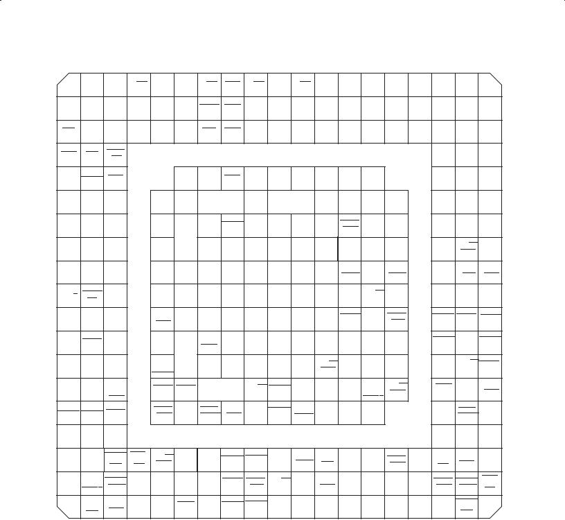
W |
|
AD27 |
VCCP |
C/BE3 |
IDSEL |
AD19 |
C/BE2 |
STOP |
C/BE1 |
VCCP |
C/BE0 |
AD4 |
AD0 |
TPB0N |
TPA0N |
TPB1N |
NC |
TPA1N |
|
|
V |
AD30 |
AD29 |
AD26 |
AD24 |
AD23 |
AD18 |
FRAME |
PERR |
AD15 |
AD11 |
AD7 |
AD3 |
PC2 |
TPB0P |
TPA0P |
TPB1P |
AVDD |
TPA1P |
VDPLL |
|
(TEST3) |
_33 |
|||||||||||||||||||
|
|
|
|
|
|
|
|
|
|
|
|
|
|
|
|
|
|
|||
U |
REQ |
AD31 |
AD28 |
AD25 |
AD22 |
AD17 |
IRDY |
SERR |
AD14 |
AD10 |
AD6 |
AD2 |
PC1 |
AGND |
TPBIAS0 |
AGND |
TPBIAS1 |
R0 |
R1 |
|
(TEST2) |
||||||||||||||||||||
|
|
|
|
|
|
|
|
|
|
|
|
|
|
|
|
|
|
|
||
T |
GRST |
GNT |
RI_OUT |
|
|
|
|
|
|
|
|
|
|
|
|
|
VSSPLL |
VDPLL |
RSVD |
|
//PME |
|
|
|
|
|
|
|
|
|
|
|
|
|
|||||||
|
|
|
|
|
|
|
|
|
|
|
|
|
|
|
|
|
_15 |
|
||
R |
|
|
|
|
|
|
|
|
|
|
|
PC0 |
|
|
|
|
PHY_ |
XI |
|
|
MFUNC6 SUSPEND |
PRST |
|
|
AD21 |
AD16 |
TRDY |
AD13 |
AD9 |
AD5 |
AVDD |
AVDD |
|
|
TEST_ |
XO |
|||||
|
|
(TEST1) |
|
|
||||||||||||||||
|
|
|
|
|
|
|
|
|
|
|
|
|
|
|
|
MA |
|
|
||
|
|
|
|
|
|
|
|
|
|
|
|
|
|
|
|
|
|
|
||
P |
MFUNC2 MFUNC3 MFUNC4 |
|
PCLK |
AD20 |
|
|
PAR |
|
|
TEST0 |
|
VSSPLL |
CNA |
|
B_CAD1 |
B_CAD2 |
B_CAD0 |
|||
|
|
|
|
|
|
|
//B_D4 |
//B_D11 |
//B_D3 |
|||||||||||
|
|
|
|
|
|
|
|
|
|
|
|
|
|
|
|
|
||||
N |
DATA |
LATCH MFUNC0 |
|
MFUNC5 |
|
VCC |
DEVSEL |
AD12 |
AD8 |
AD1 |
AGND |
B_CCD1 |
|
B_CAD4 |
|
B_RSVD |
B_CAD5 |
B_CAD6 |
||
|
|
//B_CD1 |
|
//B_D12 |
|
//B_D14 |
//B_D6 |
//B_D13 |
||||||||||||
|
|
|
|
|
|
|
|
|
|
|
|
|
|
|
||||||
M |
CLK_48 |
SDA |
SCL |
|
MFUNC1 |
|
VCC |
GND |
VCC |
VCC |
CPS |
VCC |
B_CAD3 |
B_CAD8 |
B_CAD7 |
|
B_CAD9 |
B_CC/BE0 |
VR_ |
|
|
|
//B_D5 |
//B_D15 |
//B_D7 |
|
//B_A10 |
//B_CE1 |
PORT |
||||||||||||
|
|
|
|
|
|
|
|
|
|
|
|
|
|
|||||||
L |
RSVD |
RSVD |
RSVD |
|
RSVD |
CLOCK SPKROUT |
GND |
GND |
GND |
GND |
GND |
B_CAD15 |
|
B_CAD13 |
|
B_CAD12 |
B_CAD11 B_CAD10 |
|||
|
//B_IOWR |
|
//B_IORD |
|
//B_A11 |
//B_OE |
//B_CE2 |
|||||||||||||
|
|
|
|
|
|
|
|
|
|
|
|
|
|
|
||||||
K |
SM_R/B |
SM_PHYS |
RSVD |
|
RSVD |
|
RSVD |
VCC |
GND |
GND |
GND |
VCC |
B_CPAR |
B_CC/BE1 B_RSVD |
|
B_CAD16 B_CAD14 |
VCCB |
|||
_WP |
|
|
//B_A13 |
//B_A8 |
//B_A18 |
|
//B_A17 |
//B_A9 |
||||||||||||
|
|
|
|
|
|
|
|
|
|
|
|
|
|
|||||||
J |
SD_DAT2 |
SD_DAT3 |
SD_CMD// |
|
SD_CLK |
SD_DAT1 SM_CLE |
VCC |
GND |
GND |
GND |
VCC |
B_CIRDY |
|
B_CGNT |
|
B_CSTOP B_CPERR |
B_CBLOCK |
|||
|
|
//B_WE |
|
|||||||||||||||||
|
//SM_D6 |
//SM_D7 |
SM_ALE |
|
//SM_RE //SM_D5 |
|
|
|
|
|
|
//B_A15 |
|
|
//B_A20 |
//B_A14 |
//B_A19 |
|||
H |
VR_ |
|
SD_DAT0 |
|
MS_DATA3// |
|
SD_WP// |
|
|
|
|
|
|
B_CAD19 |
B_CAD18 |
|
B_CTRDY B_CCLK |
B_CDEVSEL |
||
VR_EN |
|
SD_DAT3 |
|
VCC |
VCC |
VCC |
VCC |
VCC |
GND |
|
||||||||||
PORT |
//SM_D4 |
|
|
SM_CE |
//B_A25 |
//B_A7 |
|
//B_A22 |
//B_A16 |
//B_A21 |
||||||||||
|
//SM_D3 |
|
|
|||||||||||||||||
|
|
|
|
|
|
|
|
|
|
|
|
|
||||||||
|
|
|
|
|
|
|
|
|
|
|
|
|
|
|
|
|
|
|
||
|
MS_SDIO |
MS_DATA1 |
MS_DATA2 |
|
MS_CLK// |
|
|
|
A_CAD20 A_CPAR |
A_CAD14 A_CC/BE0 |
|
|
B_CAD21 |
|
B_CAD17 B_CC/BE2B_CFRAME |
|||||
G |
(DATA0)// |
|
|
GND |
GND |
GND |
|
|
||||||||||||
//SD_DAT1 |
//SD_DAT2 |
|
SD_CLK// |
|
|
|
||||||||||||||
|
|
|
|
//B_A24 |
//B_A12 |
//B_A23 |
||||||||||||||
|
SD_DAT0// |
//SM_D1 |
//SM_D2 |
|
SM_EL_WP |
|
|
|
//A_A6 |
//A_A13 |
//A_A9 |
//A_CE1 |
|
|
//B_A5 |
|
|
|||
|
SM_D0 |
|
|
|
|
|
|
|
|
|
|
|
|
|
|
|
||||
F |
MC_PWR MC_PWR |
MS_BS// |
|
MS_CD SM_CD |
|
|
A_CC/BE2 A_CPERR |
|
A_CAD6 |
|
B_CSTSCHG B_CC/BE3 |
|
B_CRST |
B_CAD20 B_CVS2 |
||||||
_CTRL_0 |
_CTRL_1 |
SD_CMD |
|
|
|
//A_A12 |
//A_A14 |
|
//A_D13 |
|
//B_BVD1 |
//B_REG |
|
//B_RESET |
//B_A6 |
//B_VS2 |
||||
|
//SM_WE |
|
|
|
|
|
|
|
(STSCHG/RI) |
|
|
|
|
|||||||
|
|
|
|
|
|
|
|
|
|
|
|
|
|
|
|
|
|
|||
E |
B_USB_EN A_USB_EN |
SD_CD |
|
A_CCD2 A_CAD24 |
A_CREQ |
A_CVS2 |
A_CCLK |
A_CBLOCK A_CAD15 |
A_CAD8 |
A_CAD3 |
A_CAD0 |
|
|
B_CAD23 B_CREQ |
B_CAD22 |
|||||
|
//A_CD2 |
//A_A2 |
//A_INPACK |
//A_VS2 |
//A_A16 |
//A_A19 |
//A_IOWR |
//A_D15 |
//A_D5 |
//A_D3 |
|
|
//B_A3 |
//B_INPACK |
//B_A4 |
|||||
|
|
|
|
|
|
|
|
|
|
|
|
|||||||||
D |
A_CAD31 |
A_RSVD |
A_CAD29 |
|
|
|
|
|
|
|
|
|
|
|
|
|
B_CAD26 B_CAD24 |
VCCB |
||
|
//A_D10 |
//A_D2 |
//A_D1 |
|
|
|
|
|
|
|
|
|
|
|
|
|
//B_A0 |
//B_A2 |
|
|
C |
A_CAD30 |
A_CAD28 |
A_CCLKRUN A_CINT// |
A_CC/BE3 A_CAD22 A_CAD19 A_CFRAME A_CDEVSEL A_RSVD |
A_CAD13 A_CAD11 |
A_CAD7 |
A_CAD4 |
A_CCD1 |
B_CAD27 |
B_CAUDIO |
B_CVS1 B_CAD25 |
|||||||||
//A_WP A_READY |
//B_BVD2 |
|||||||||||||||||||
|
//A_D9 |
//A_D8 |
(IOIS16) |
(IREQ) |
//A_REG |
//A_A4 |
//A_A25 |
//A_A23 |
//A_A21 |
//A_A18 |
//A_IORD |
//A_OE |
//A_D7 |
//A_D12 |
//A_CD1 |
//B_D0 |
(SPKR) |
//B_VS1 |
//B_A1 |
|
B |
A_CAD27 A_CSTSCHG A_CSERR A_CAD26 |
A_CAD23 A_CAD21 A_CAD18 A_CIRDY |
A_CGNT A_CC/BE1 A_CAD12 A_CAD10 |
A_RSVD |
A_CAD1 |
B_CAD31 |
B_CAD29 |
B_CCD2 |
B_CSERR |
B_CINT |
||||||||||
//A_D0 |
//A_BVD1 |
//A_WAIT |
//A_A0 |
//A_A3 |
//A_A5 |
//A_A7 |
//A_A15 |
//A_WE |
//A_A8 |
//A_A11 |
//A_CE2 |
//A_D14 |
//A_D4 |
//B_D10 |
//B_D1 |
//B_CD2 |
//B_WAIT |
//B_READY |
||
|
(STSCHG/RI) |
(IREQ) |
||||||||||||||||||
|
|
|
|
|
|
|
|
|
|
|
|
|
|
|
|
|
|
|||
A |
|
A_CAUDIO |
A_CVS1 |
A_CAD25 |
VCCA |
A_CRST |
A_CAD17 A_CTRDY A_CSTOP A_CAD16 |
|
A_CAD9 |
A_CAD5 |
A_CAD2 |
B_RSVD |
B_CAD30 B_CAD28 B_CCLKRUN |
|
||||||
|
//A_BVD2 |
//A_VS1 |
//A_A1 |
//A_RESET |
//A_A24 |
//A_A22 |
//A_A20 |
//A_A17 |
VCCA |
//A_A10 |
//A_D6 |
//A_D11 |
//B_D2 |
//B_D9 |
//B_D8 |
//B_WP |
|
|||
|
(IOIS16) |
|
||||||||||||||||||
|
|
(SPKR) |
|
|
|
|
|
|
|
|
|
|
|
|
|
|
|
|
||
|
1 |
2 |
3 |
4 |
5 |
6 |
7 |
8 |
9 |
10 |
11 |
12 |
13 |
14 |
15 |
16 |
17 |
18 |
19 |
|
Figure 2−2. PCI7421 GHK/ZHK-Package Terminal Diagram
2−2
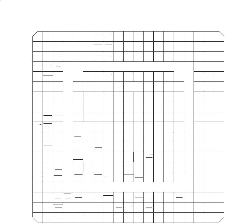
W |
|
AD27 |
VCCP |
C/BE3 |
IDSEL |
AD19 |
C/BE2 |
STOP |
C/BE1 |
VCCP |
C/BE0 |
AD4 |
AD0 |
TPB0N |
TPA0N |
TPB1N |
NC |
TPA1N |
|
|
V |
AD30 |
AD29 |
AD26 |
AD24 |
AD23 |
AD18 |
FRAME |
PERR |
AD15 |
AD11 |
AD7 |
AD3 |
PC2 |
TPB0P |
TPA0P |
TPB1P |
AVDD |
TPA1P |
VDPLL |
|
(TEST3) |
_33 |
|||||||||||||||||||
|
|
|
|
|
|
|
|
|
|
|
|
|
|
|
|
|
|
|||
U |
REQ |
AD31 |
AD28 |
AD25 |
AD22 |
AD17 |
IRDY |
SERR |
AD14 |
AD10 |
AD6 |
AD2 |
PC1 |
AGND |
TPBIAS0 |
AGND |
TPBIAS1 |
R0 |
R1 |
|
(TEST2) |
||||||||||||||||||||
|
|
|
|
|
|
|
|
|
|
|
|
|
|
|
|
|
|
|
||
T |
GRST |
GNT |
RI_OUT |
|
|
|
|
|
|
|
|
|
|
|
|
|
VSSPLL |
VDPLL |
RSVD |
|
//PME |
|
|
|
|
|
|
|
|
|
|
|
|
|
_15 |
||||||
|
|
|
|
|
|
|
|
|
|
|
|
|
|
|
|
|
|
|||
R |
|
|
|
|
|
|
|
|
|
|
|
PC0 |
|
|
|
|
PHY_ |
XI |
|
|
MFUNC6 SUSPEND |
PRST |
|
|
AD21 |
AD16 |
TRDY |
AD13 |
AD9 |
AD5 |
AVDD |
AVDD |
|
|
TEST_ |
XO |
|||||
|
|
(TEST1) |
|
|
||||||||||||||||
|
|
|
|
|
|
|
|
|
|
|
|
|
|
|
|
MA |
|
|
||
|
|
|
|
|
|
|
|
|
|
|
|
|
|
|
|
|
|
|
||
P |
MFUNC2 MFUNC3 MFUNC4 |
|
PCLK |
AD20 |
|
|
PAR |
|
|
TEST0 |
|
VSSPLL |
CNA |
|
RSVD |
RSVD |
RSVD |
|||
N |
DATA |
LATCH MFUNC0 |
|
MFUNC5 |
|
VCC |
DEVSEL |
AD12 |
AD8 |
AD1 |
AGND |
RSVD |
|
RSVD |
|
RSVD |
RSVD |
RSVD |
||
M |
CLK_48 |
SDA |
SCL |
|
MFUNC1 |
|
VCC |
GND |
VCC |
VCC |
CPS |
VCC |
RSVD |
RSVD |
RSVD |
|
RSVD |
RSVD |
VR_ |
|
|
|
|
PORT |
|||||||||||||||||
|
|
|
|
|
|
|
|
|
|
|
|
|
|
|
|
|
|
|
||
L |
SC_ |
|
|
|
SC_ |
|
|
GND |
|
|
|
|
|
|
|
|
|
|
|
|
SC_CD |
SC_OC |
|
PWR_ |
CLOCK SPKROUT |
GND |
GND |
GND |
GND |
RSVD |
|
RSVD |
|
RSVD |
RSVD |
RSVD |
|||||
DATA |
|
|
|
|||||||||||||||||
|
|
|
|
CTRL |
|
|
|
|
|
|
|
|
|
|
|
|
|
|
||
|
|
|
|
|
|
|
|
|
|
|
|
|
|
|
|
|
|
|
||
K |
SM_R/B// SM_PHYS |
SC_RST |
|
SC_CLK |
|
SC_VCC |
VCC |
GND |
GND |
GND |
VCC |
RSVD |
RSVD |
RSVD |
|
RSVD |
RSVD |
RSVD |
||
|
_WP// |
|
|
_5V |
|
|||||||||||||||
|
SC_RFU SC_FCB |
|
|
|
|
|
|
|
|
|
|
|
|
|
|
|
|
|||
J |
SD_DAT2 |
SD_DAT3 |
SD_CMD// |
|
SD_CLK// |
SD_DAT1// |
SM_CLE// |
|
|
|
|
VCC |
|
|
|
|
|
|
|
|
//SM_D6// |
//SM_D7// |
SM_ALE// |
|
SM_RE// SM_D5// |
VCC |
GND |
GND |
GND |
RSVD |
|
RSVD |
|
RSVD |
RSVD |
RSVD |
|||||
|
|
|
|
|||||||||||||||||
|
SC_GPIO4 SC_GPIO3 SC_GPIO2 |
|
SC_GPIO1 SC_GPIO5 SC_GPIO0 |
|
|
|
|
|
|
|
|
|
|
|
|
|||||
H |
VR_ |
|
SD_DAT0// |
|
MS_DATA3// |
|
SD_WP// |
|
|
|
|
|
GND |
|
|
|
|
|
|
|
VR_EN |
SM_D4// |
|
SD_DAT3 |
|
VCC |
VCC |
VCC |
VCC |
VCC |
RSVD |
RSVD |
|
RSVD |
RSVD |
RSVD |
|||||
PORT |
|
|
SM_CE |
|
||||||||||||||||
|
|
SC_GPIO6 |
|
//SM_D3 |
|
|
|
|
|
|
|
|
|
|
|
|
|
|||
|
|
|
|
|
|
|
|
|
|
|
|
|
|
|
|
|
|
|
||
|
MS_SDIO |
MS_DATA1 |
MS_DATA2 |
|
MS_CLK// |
|
|
|
A_CAD20 A_CPAR |
A_CAD14 A_CC/BE0 |
|
|
|
|
|
|
|
|||
G |
(DATA0)// |
|
|
GND |
GND |
GND |
|
RSVD |
|
RSVD |
RSVD |
RSVD |
||||||||
//SD_DAT1 |
//SD_DAT2 |
|
SD_CLK// |
|
|
|
||||||||||||||
SD_DAT0// |
|
|
//A_A6 |
//A_A13 |
//A_A9 |
//A_CE1 |
|
|
||||||||||||
|
SM_D0 |
//SM_D1 |
//SM_D2 |
|
SM_EL_WP |
|
|
|
|
|
|
|
|
|
|
|
|
|
|
|
F |
MC_PWR MC_PWR |
MS_BS// |
|
MS_CD SM_CD |
|
|
A_CC/BE2 A_CPERR |
|
A_CAD6 |
|
|
|
|
|
|
|
||||
SD_CMD |
|
|
|
|
|
RSVD |
RSVD |
|
RSVD |
RSVD |
RSVD |
|||||||||
_CTRL_0 |
_CTRL_1 |
|
|
|
//A_A12 |
//A_A14 |
|
//A_D13 |
|
|
||||||||||
|
//SM_WE |
|
|
|
|
|
|
|
|
|
|
|
|
|
||||||
|
|
|
|
|
|
|
|
|
|
|
|
|
|
|
|
|
|
|
||
E |
B_USB_EN A_USB_EN |
SD_CD |
|
A_CCD2 A_CAD24 |
A_CREQ |
A_CVS2 A_CCLK |
A_CBLOCK A_CAD15 |
A_CAD8 |
A_CAD3 |
A_CAD0 |
|
|
RSVD |
RSVD |
RSVD |
|||||
|
//A_CD2 |
//A_A2 |
//A_INPACK |
//A_VS2 |
//A_A16 |
//A_A19 |
//A_IOWR |
//A_D15 |
//A_D5 |
//A_D3 |
|
|
||||||||
|
|
|
|
|
|
|
|
|
|
|
|
|
|
|||||||
D |
A_CAD31 A_RSVD |
A_CAD29 |
|
|
|
|
|
|
|
|
|
|
|
|
|
RSVD |
RSVD |
RSVD |
||
//A_D10 |
//A_D2 |
//A_D1 |
|
|
|
|
|
|
|
|
|
|
|
|
|
|||||
|
|
|
|
|
|
|
|
|
|
|
|
|
|
|
|
|
||||
C |
A_CAD30 A_CAD28 |
A_CCLKRUN A_CINT// |
A_CC/BE3 A_CAD22 A_CAD19 A_CFRAME A_CDEVSEL |
A_RSVD |
A_CAD13 A_CAD11 |
A_CAD7 |
A_CAD4 |
A_CCD1 |
RSVD |
RSVD |
RSVD |
RSVD |
||||||||
//A_D9 |
//A_D8 |
//A_WP |
A_READY |
//A_REG |
//A_A4 |
//A_A25 |
//A_A23 |
//A_A21 |
//A_A18 |
//A_IORD |
//A_OE |
//A_D7 |
//A_D12 |
//A_CD1 |
||||||
|
(IOIS16) |
(IREQ) |
|
|
|
|
||||||||||||||
|
|
|
|
|
|
|
|
|
|
|
|
|
|
|
|
|
|
|||
B |
A_CAD27 A_CSTSCHG A_CSERR A_CAD26 |
A_CAD23 A_CAD21 A_CAD18 |
A_CIRDY |
A_CGNT A_CC/BE1 A_CAD12 A_CAD10 |
A_RSVD |
A_CAD1 |
RSVD |
RSVD |
RSVD |
RSVD |
RSVD |
|||||||||
//A_D0 |
//A_BVD1 |
//A_WAIT |
//A_A0 |
//A_A3 |
//A_A5 |
//A_A7 |
//A_A15 |
//A_WE |
//A_A8 |
//A_A11 |
//A_CE2 |
//A_D14 |
//A_D4 |
|||||||
(STSCHG/RI) |
||||||||||||||||||||
|
|
|
|
|
|
|||||||||||||||
A |
|
A_CAUDIO |
A_CVS1 A_CAD25 |
VCCA |
A_CRST |
A_CAD17 A_CTRDY A_CSTOP A_CAD16 |
|
A_CAD9 A_CAD5 |
A_CAD2 |
RSVD |
RSVD |
RSVD |
RSVD |
|
||||||
|
//A_BVD2 |
//A_VS1 |
//A_A1 |
//A_RESET |
//A_A24 |
//A_A22 |
//A_A20 |
//A_A17 |
VCCA |
//A_A10 |
//A_D6 |
//A_D11 |
|
|||||||
|
|
(SPKR) |
|
|
|
|
|
|
|
|
|
|
|
|
|
|
|
|
|
|
|
1 |
2 |
3 |
4 |
5 |
6 |
7 |
8 |
9 |
10 |
11 |
12 |
13 |
14 |
15 |
16 |
17 |
18 |
19 |
|
Figure 2−3. PCI7611 GHK/ZHK-Package Terminal Diagram
2−3
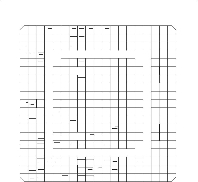
W |
|
AD27 |
VCCP |
C/BE3 |
IDSEL |
AD19 |
C/BE2 |
STOP |
C/BE1 |
VCCP |
C/BE0 |
AD4 |
AD0 |
TPB0N |
TPA0N |
TPB1N |
NC |
TPA1N |
|
|
V |
AD30 |
AD29 |
AD26 |
AD24 |
AD23 |
AD18 |
FRAME |
PERR |
AD15 |
AD11 |
AD7 |
AD3 |
PC2 |
TPB0P |
TPA0P |
TPB1P |
AVDD |
TPA1P |
VDPLL_ |
|
|
|
|
|
|
|
|
|
|
|
|
|
|
(TEST3) |
|
|
|
|
|
33 |
|
U |
REQ |
AD31 |
AD28 |
AD25 |
AD22 |
AD17 |
IRDY |
SERR |
AD14 |
AD10 |
AD6 |
AD2 |
PC1 |
AGND |
TPBIAS0 |
AGND |
TPBIAS1 |
R0 |
R1 |
|
(TEST2) |
||||||||||||||||||||
|
|
|
|
|
|
|
|
|
|
|
|
|
|
|
|
|
|
|
||
T |
GRST |
GNT |
RI_OUT |
|
|
|
|
|
|
|
|
|
|
|
|
|
VSSPLL VDPLL_ |
RSVD |
||
|
|
|
//PME |
|
|
|
|
|
|
|
|
|
|
|
|
|
|
15 |
|
|
R |
|
|
|
|
|
|
|
|
|
|
|
PC0 |
|
|
|
|
PHY_ |
XI |
|
|
MFUNC6 SUSPEND |
PRST |
|
|
AD21 |
AD16 |
TRDY |
AD13 |
AD9 |
AD5 |
AVDD |
AVDD |
|
|
TEST_ |
XO |
|||||
|
|
(TEST1) |
|
|
||||||||||||||||
|
|
|
|
|
|
|
|
|
|
|
|
|
|
|
|
MA |
|
|
||
|
|
|
|
|
|
|
|
|
|
|
|
|
|
|
|
|
|
|
||
P |
MFUNC2 MFUNC3 MFUNC4 |
|
PCLK |
AD20 |
|
|
PAR |
|
|
TEST0 |
|
VSSPLL |
CNA |
|
RSVD |
RSVD |
RSVD |
|||
N |
DATA |
LATCH MFUNC0 |
|
MFUNC5 |
|
VCC |
DEVSEL |
AD12 |
AD8 |
AD1 |
AGND |
RSVD |
|
RSVD |
|
RSVD |
RSVD |
RSVD |
||
M |
CLK_48 |
SDA |
SCL |
|
MFUNC1 |
|
VCC |
GND |
VCC |
VCC |
CPS |
VCC |
RSVD |
RSVD |
RSVD |
|
RSVD |
RSVD |
VR_ |
|
|
|
|
PORT |
|||||||||||||||||
|
|
|
|
|
|
|
|
|
|
|
|
|
|
|
|
|
|
|
||
L |
RSVD |
RSVD |
RSVD |
|
RSVD |
CLOCK SPKROUT |
GND |
GND |
GND |
GND |
GND |
RSVD |
|
RSVD |
|
RSVD |
RSVD |
RSVD |
||
K |
SM_R/B SM_PHYS |
RSVD |
|
RSVD |
|
RSVD |
VCC |
GND |
GND |
GND |
VCC |
RSVD |
RSVD |
RSVD |
|
RSVD |
RSVD |
RSVD |
||
|
|
_WP |
|
|
|
|
|
|
|
|
|
|
|
|
|
|
|
|
|
|
J |
SD_DAT2 |
SD_DAT3 |
SD_CMD// |
|
SD_CLK// |
SD_DAT1 SM_CLE |
VCC |
GND |
GND |
GND |
VCC |
RSVD |
|
RSVD |
|
RSVD |
RSVD |
RSVD |
||
|
//SM_D6 |
//SM_D7 |
SM_ALE |
|
SM_RE //SM_D5 |
|
|
|
|
|
|
|
|
|
|
|
|
|
||
H |
VR_ |
|
SD_DAT0 |
|
MS_DATA3// |
|
SD_WP// |
|
|
|
|
|
|
|
|
|
|
|
|
|
VR_EN |
|
SD_DAT3 |
|
VCC |
VCC |
VCC |
VCC |
VCC |
GND |
RSVD |
RSVD |
|
RSVD |
RSVD |
RSVD |
|||||
PORT |
//SM_D4 |
|
|
SM_CE |
|
|||||||||||||||
|
|
|
//SM_D3 |
|
|
|
|
|
|
|
|
|
|
|
|
|
||||
|
MS_SDIO |
MS_DATA1 |
MS_DATA2 |
|
MS_CLK// |
|
|
|
A_CAD20 A_CPAR |
A_CAD14 A_CC/BE0 |
|
|
|
|
|
|
|
|||
G |
(DATA0)// |
|
|
GND |
GND |
GND |
|
RSVD |
|
RSVD |
RSVD |
RSVD |
||||||||
//SD_DAT1 |
//SD_DAT2 |
|
SD_CLK// |
|
|
|
||||||||||||||
SD_DAT0// |
|
|
//A_A6 |
//A_A13 |
//A_A9 |
//A_CE1 |
|
|
||||||||||||
|
SM_D0 |
//SM_D1 |
//SM_D2 |
|
SM_EL_WP |
|
|
|
|
|
|
|
|
|
|
|
|
|
|
|
F |
MC_PWR MC_PWR |
MS_BS// |
|
MS_CD |
SM_CD |
|
|
A_CC/BE2 A_CPERR |
|
A_CAD6 |
|
|
|
|
|
|
|
|||
SD_CMD |
|
|
|
|
|
RSVD |
RSVD |
|
RSVD |
RSVD |
RSVD |
|||||||||
_CTRL_0 |
_CTRL_1 |
|
|
|
//A_A12 |
//A_A14 |
|
//A_D13 |
|
|
||||||||||
|
//SM_WE |
|
|
|
|
|
|
|
|
|
|
|
|
|
||||||
|
|
|
|
|
|
|
|
|
|
|
|
|
|
|
|
|
|
|
||
E |
B_USB_EN A_USB_EN |
SD_CD |
|
A_CCD2 |
A_CAD24 |
A_CREQ |
A_CVS2 |
A_CCLK |
A_CBLOCK |
A_CAD15 |
A_CAD8 |
A_CAD3 |
A_CAD0 |
|
|
RSVD |
RSVD |
RSVD |
||
|
//A_CD2 |
//A_A2 |
//A_INPACK |
//A_VS2 |
//A_A16 |
//A_A19 |
//A_IOWR |
//A_D15 |
//A_D5 |
//A_D3 |
|
|
||||||||
|
|
|
|
|
|
|
|
|
|
|||||||||||
D |
A_CAD31 A_RSVD |
A_CAD29 |
|
|
|
|
|
|
|
|
|
|
|
|
|
RSVD |
RSVD |
RSVD |
||
//A_D10 |
//A_D2 |
//A_D1 |
|
|
|
|
|
|
|
|
|
|
|
|
|
|||||
|
|
|
|
|
|
|
|
|
|
|
|
|
|
|
|
|
||||
C |
A_CAD30 |
A_CAD28 A_CCLKRUN |
A_CINT// |
A_CC/BE3 A_CAD22 A_CAD19 A_CFRAME A_CDEVSEL A_RSVD |
A_CAD13 A_CAD11 |
A_CAD7 |
A_CAD4 |
A_CCD1 |
RSVD |
RSVD |
RSVD |
RSVD |
||||||||
//A_D9 |
//A_D8 |
//A_WP |
A_READY |
//A_REG |
//A_A4 |
//A_A25 |
//A_A23 |
//A_A21 |
//A_A18 |
//A_IORD |
//A_OE |
//A_D7 |
//A_D12 |
//A_CD1 |
||||||
|
(IOIS16) |
(IREQ) |
|
|
|
|
||||||||||||||
|
|
|
|
|
|
|
|
|
|
|
|
|
|
|
|
|
|
|||
B |
A_CAD27 A_CSTSCHG A_CSERR A_CAD26 |
A_CAD23 A_CAD21 A_CAD18 |
A_CIRDY |
A_CGNT A_CC/BE1 A_CAD12 A_CAD10 |
A_RSVD |
A_CAD1 |
RSVD |
RSVD |
RSVD |
RSVD |
RSVD |
|||||||||
//A_D0 |
//A_BVD1 |
//A_WAIT |
//A_A0 |
//A_A3 |
//A_A5 |
//A_A7 |
//A_A15 |
//A_WE |
//A_A8 |
//A_A11 |
//A_CE2 |
//A_D14 |
//A_D4 |
|||||||
(STSCHG/RI) |
||||||||||||||||||||
|
|
|
|
|
|
|||||||||||||||
A |
|
A_CAUDIO |
A_CVS1 A_CAD25 |
VCCA |
A_CRST |
A_CAD17 A_CTRDY A_CSTOP A_CAD16 |
|
A_CAD9 A_CAD5 |
A_CAD2 |
RSVD |
RSVD |
RSVD |
RSVD |
|
||||||
|
//A_BVD2 |
//A_VS1 |
//A_A1 |
//A_RESET |
//A_A24 |
//A_A22 |
//A_A20 |
//A_A17 |
VCCA |
//A_A10 |
//A_D6 |
//A_D11 |
|
|||||||
|
|
(SPKR) |
|
|
|
|
|
|
|
|
|
|
|
|
|
|
|
|
|
|
|
1 |
2 |
3 |
4 |
5 |
6 |
7 |
8 |
9 |
10 |
11 |
12 |
13 |
14 |
15 |
16 |
17 |
18 |
19 |
|
Figure 2−4. PCI7411 GHK/ZHK-Package Terminal Diagram
Table 2−1 lists the terminal assignments arranged in terminal-number order, with corresponding signal names for both CardBus and 16-bit PC Cards for the PCI7421 and PCI7621 GHK packages. Table 2−2 and Table 2−3 list the terminal assignments arranged in alphanumerical order by signal name, with corresponding terminal numbers for the GHK package; Table 2−2 is for CardBus signal names and Table 2−3 is for 16-bit PC Card signal names.
Terminal E5 on the GHK package is an identification ball used for device orientation.
2−4
 Loading...