


10/100 Switches
Use this guide to install the following products:
5-Port 10/100 Switch |
SD205 |
8-Port 10/100 Switch |
SD208 |
16-Port 10/100 Switch |
SD216 |
User Guide
Table of Contents
English |
3 |
Français |
15 |
Deutsch |
27 |
Italiano |
39 |
Portuguese |
51 |
Español |
63 |
1
COPYRIGHT & TRADEMARKS
Specifications are subject to change without notice. Copyright © 2003 Cisco Systems,
Inc. All rights reserved. Linksys is a registered trademark of Cisco Systems, Inc. Other brands and product names are trademarks or registered trademarks of their respective
holders.
FCC STATEMENT
Every 10/100 Switch has been tested and complies with the limits for a Class B digital device, pursuant to Part 15 of the FCC Rules. These limits are designed to provide
reasonable protection against harmful interference in a residential installation. This equipment generates, uses, and can radiate radio frequency energy and, if not installed and used according to the instructions, may cause harmful interference to radio
communications. However, there is no guarantee that interference will not occur in a particular installation. If this equipment does cause harmful interference to radio or
television reception, which is found by turning the equipment off and on, the user is encouraged to try to correct the interference by one or more of the following measures:
•Reorient or relocate the receiving antenna
•Increase the separation between the equipment or devices
•Connect the equipment to an outlet other than the receiver’s
•Consult a dealer or an experienced radio/TV technician for assistance
EC Declaration of Conformity (Europe)
In compliance with the EMC Directive 89/336/EEC, Low Voltage Directive 73/23/EEC, and Amendment Directive 93/68/EEC, this product meets the requirements of the following standards:
•EN55022 Emission
•EN55024 Immunity
Table of Contents
Chapter 1: Introduction |
4 |
The 10/100 Switch |
4 |
Features |
4 |
Chapter 2: Getting to Know the 10/100 Switch |
5 |
Overview |
5 |
Front Panel LEDs |
5 |
Back and Side Panel Features |
5 |
Chapter 3: Connecting the 10/100 Switch |
7 |
Overview |
7 |
Connecting Network Devices |
8 |
Placement Options |
9 |
Appendix A: Specifications |
10 |
Environmental |
11 |
Appendix B: Warranty Information |
12 |
SD205_SD208_SD216-EU-UG-30606NC JL
2 |
3 |

Chapter 1: Introduction
The 10/100 Switch
This newly redesigned Linksys 5-, 8-, or 16-Port 10/100 Switch can significantly increase your network traffic’s speed. A switch serves the same function as a hub in a network design—tying your network equipment together. But unlike a simple-minded hub which divides the network’s bandwidth among all the attached devices, a switch delivers full network speeds at each port. Installing this cost-effective 5-, 8-, or 16-Port 10/100 Switch can potentially increase your network speed by five, eight, or sixteen times!
It's the perfect way of integrating 10Mbps Ethernet and 100Mbps Fast Ethernet devices, too. All ports are auto speed negotiating, and have automatic MDI/MDI-X crossover detection, so you don’t have to worry about the cable type. Each port independently negotiates for best speed and halfor full-duplex mode, for up to 200Mbps of bandwidth per port. Fast store-and-forward switching prevents damaged packets from being passed on into the network.
The new, ultra-compact case design is sure to fit into your workgroup environment. Let the Linksys 5-, 8-, or 16-Port 10/100 Switch kick your 10/100 network into high gear.
Features
•Ideal for Integrating Your 10BaseT and 100BaseTX Network Hardware
•5, 8, or 16 10/100 Ports Provide Dedicated Bandwidth in Halfor FullDuplex Modes
•Each Port Supports Auto MDI/MDI-X Cable Detection
•Compatible with All Major Network Operating Systems
•Advanced Store-and-Forward Packet Switching Optimizes Data Transfers
•Auto Partitioning Protects PCs from Downed Network Lines
•Signal Regeneration Ensures Data Transfer Integrity
•Limited Lifetime Warranty
Chapter 2: Getting to Know the 10/100 Switch
Overview
The 5-, 8-, and 16-Port 10/100 Switches differ in number of LEDs and ports. Pictured here is the 5-Port 10/100 Switch; however, the other Switches are similar in form.
Front Panel LEDs
Figure 2-1
System Green. The System LED will light up when the Switch is powered on.
1-5, 1-8, or 1-16 Green. Each LED will light up when there is a connection made through its corresponding port. It will flash when there is activity on its corresponding port.
Back and Side Panel Features
Figure 2-2
The network ports are located on the back panel of the Switch.
1-5, 1-8, or 1-16 These ports are connection points for PCs and other network devices, such as additional switches.
4 |
5 |

Figure 2-3
The power port is located on the side panel of the Switch (see Figure 2-3).
(power) |
The power port is where you will connect the included power |
|
adapter. |
Figure 2-4
The security slot is located on the other side panel (see Figure 2-4).
(security slot) The security slot is where you can attach a lock so the Switch will be protected from theft.
Chapter 3: Connecting the
10/100 Switch
Overview
This chapter will explain how to connect network devices to the Switch. For an example of a typical network configuration, see the application diagram shown in Figure 3-1.
|
Cable/DSL |
Broadband |
|
|
|
Internet |
Modem |
Router |
Desktop PC |
Notebook |
Access Point |
Figure 3-1
When you connect your network devices, make sure you don’t exceed the maximum cabling distances, which are listed in the following table:
Maximum Cabling Distances
From |
To |
Maximum Distance |
Switch |
Switch or Hub* |
100 meters (328 feet) |
Switch or Hub |
Computer |
100 meters (328 feet) |
*A hub refers to any type of 100Mbps hub, including regular hubs and stackable hubs. A 10Mbps hub connected to another 10Mbps hub can span up to 100 meters (328 feet).
6 |
7 |
Connecting Network Devices
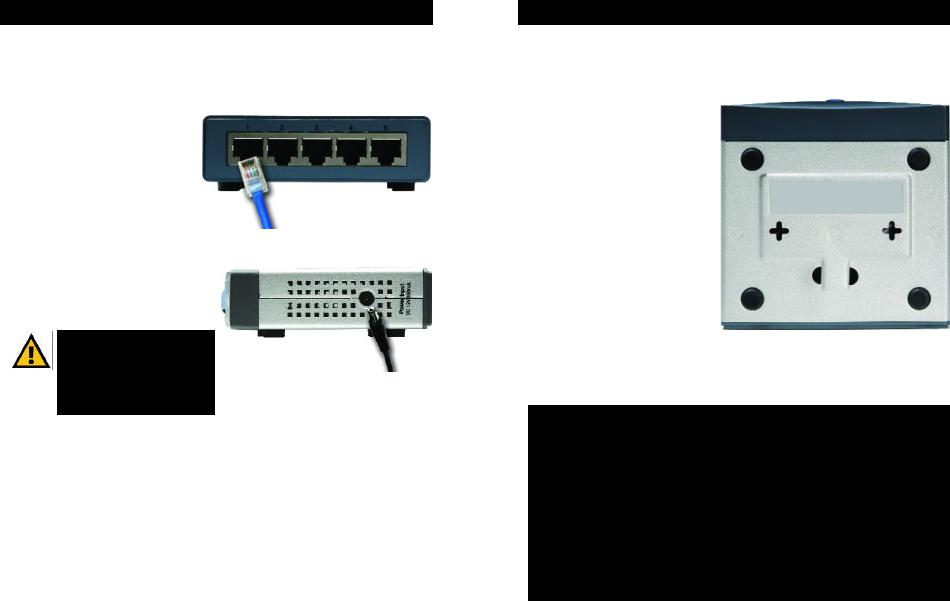
Follow these instructions for the 5-, 8-, and 16-Port 10/100 Switches (the 5-Port 10/100 Switch is shown in Figures 3-2 and 3-3).
1. Make sure all the devices you will connect to the Switch are powered off.
2.Connect a Category 5 Ethernet network cable to one of the numbered ports on the Switch.
3.Connect the other end to a PC or other network device.
4.Repeat steps 2 and 3 to connect additional devices.
5.Connect the supplied power adapter to the power port on the Switch’s side panel.
Note: Make sure you use the power adapter included with the Switch. Using a different power adapter may result in damage to the Switch.
Figure 3-2
Figure 3-3
6.Plug the other end of the adapter into a power outlet.
7.Power on the devices connected to the Switch. Each active port’s corresponding LED will light up on the Switch.
Proceed to the following section, “Placement Options.”
Placement Options
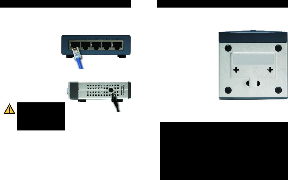
Set the Switch on its four rubber feet. For the 8- or 16-Port 10/100 Switch, you can choose to hang it on a wall using its wall-mount slots. To use this option, follow these instructions:
1.The wall-mount slots are two crisscross slots on the Switch’s bottom panel, as shown in Figure 3-4. Attach two screws to the wall, so that the Switch’s wall-mount slots line up with the two screws.
2.Maneuver the Switch so the screws are inserted into the two slots.
Congratulations! |
|
The installation of the 10/100 |
Figure 3-4 |
Switch is complete. |
|
For help with the installation or operation of the 10/100 Switch, contact Linksys Technical Support at one of the phone numbers listed on the Technical Support insert or one of the Internet addresses below:
E-mail: Europe |
europe-support@linksys.com |
United Kingdom & Ireland |
uks@linksys.com |
Latin America |
latam-soporte@linksys.com |
For unlisted regions or the most up-to-date contact information, please visit the website below:
Website |
http://www.linksys.com/international |
8 |
9 |

Appendix A: Specifications
Model Number |
SD205 |
5-Port 10/100 Switch |
|
SD208 |
8-Port 10/100 Switch |
|
SD216 |
16-Port 10/100 Switch |
Standards |
IEEE 802.3, IEEE 802.3u |
|
Ports |
|
|
SD205 |
5 RJ-45 10/100, Power |
|
SD208 |
8 RJ-45 10/100, Power |
|
SD216 |
16 RJ-45 10/100, Power |
|
Cabling Type |
Category 5 Ethernet |
|
LEDs |
|
|
SD205 |
System, Port Status 1, 2, 3, 4, and 5 |
|
SD208 |
System, Port Status 1, 2, 3, 4, 5, 6, 7, and 8 |
|
SD216 |
System, Port Status 1, 2, 3, 4, 5, 6, 7, 8, 9, 10, |
|
|
11, 12, 13, 14, 15, and 16 |
|
Environmental
Dimensions
SD205 |
93 mm x 30 mm x 90 mm |
|
(3,66" x 1,18" x 3,54") |
SD208 |
130 mm x 30 mm x 127 mm |
|
(5,12" x 1,18" x 5,00") |
SD216 |
130 mm x 40 mm x 127 mm |
|
(5,12" x 1,57" x 5,00") |
Unit Weight
SD205 |
0,23 kg |
(8 oz.) |
SD208 |
0,43 kg |
(15 oz.) |
SD216 |
0,54 kg |
(19 oz.) |
Power
SD205 |
DC 12V, 500 mA |
SD208 |
DC 12V, 500 mA |
SD216 |
DC 12V, 1,5 A |
Certifications |
FCC Class B, CE Mark |
Operating Temp. |
0ºC to 50ºC (32ºF to 122ºF) |
Storage Temp. |
-40ºC to 70ºC (-40ºF to 158ºF) |
Operating Humidity |
20% to 95%, Non-Condensing |
Storage Humidity |
5% to 90%, Non-Condensing |
10 |
11 |
Appendix B: Warranty Information
LIMITED WARRANTY
Linksys warrants to the original end user purchaser (“You”) that, for a period of the product’s lifetime, (the “Warranty Period”) Your Linksys product will be free of defects in materials and workmanship under normal use. Your exclusive remedy and Linksys’s entire liability under this warranty will be for Linksys at its option to repair or replace the product or refund Your purchase price less any rebates.
If the product proves defective during the Warranty Period call Linksys Technical Support in order to obtain a Return Authorization Number. BE SURE TO HAVE YOUR PROOF OF PURCHASE ON HAND WHEN CALLING. When returning a product, mark the Return
Authorization Number clearly on the outside of the package and include a copy of your original proof of purchase. RETURN REQUESTS CANNOT BE PROCESSED WITHOUT
PROOF OF PURCHASE. You are responsible for shipping defective products to Linksys. Linksys pays for UPS Ground shipping from Linksys back to You only. Customers located outside of the United States of America and Canada are responsible for all shipping and handling charges.
ALL IMPLIED WARRANTIES AND CONDITIONS OF MERCHANTABILITY OR FITNESS FOR A PARTICULAR PURPOSE ARE LIMITED TO THE DURATION OF THE WARRANTY PERIOD. ALL OTHER EXPRESS OR IMPLIED CONDITIONS, REPRESENTATIONS AND
WARRANTIES, INCLUDING ANY IMPLIED WARRANTY OF NON-INFRINGEMENT, ARE DISCLAIMED. Some jurisdictions do not allow limitations on how long an implied
warranty lasts, so the above limitation may not apply to You. This warranty gives You specific legal rights, and You may also have other rights which vary by jurisdiction.
TO THE EXTENT NOT PROHIBITED BY LAW, IN NO EVENT WILL LINKSYS BE LIABLE FOR ANY LOST DATA, REVENUE OR PROFIT, OR FOR SPECIAL, INDIRECT,
CONSEQUENTIAL, INCIDENTAL OR PUNITIVE DAMAGES, HOWEVER CAUSED REGARDLESS OF THE THEORY OF LIABILITY, ARISING OUT OF OR RELATED TO THE USE OF OR INABILITY TO USE THE PRODUCT, EVEN IF LINKSYS HAS BEEN ADVISED
OF THE POSSIBILITY OF SUCH DAMAGES. IN NO EVENT WILL LINKSYS' LIABILITY EXCEED THE AMOUNT PAID BY YOU FOR THE PRODUCT.
The foregoing limitations will apply even if any warranty or remedy provided under this
Section fails of its essential purpose. Some jurisdictions do not allow the exclusion or limitation of incidental or consequential damages, so the above limitation or exclusion
may not apply to You.
This Warranty is valid and may be processed only in the country of purchase.
Please direct all inquiries to: Linksys, P.O. Box 18558, Irvine, CA 92623.
12 |
13 |
COPYRIGHT & MARQUES DE COMMERCE
Les spécifications peuvent être modifiées sans préavis. Copyright © 2003 Cisco
Systems, Inc. Tous droits réservés. Linksys est une marque déposée de Cisco Systems, Inc. Les autres noms de marque et de produit sont des marques commerciales ou
déposées de leur détenteur respectif.
Déclaration de conformité CE (Europe)
Conformément aux directives 89/336/EEC sur la compatibilité électromagnétique, 73/23/EEC sur les basses tensions et 93/68/EEC sur les modifications, ce produit satisfait
aux exigences des normes suivantes :
•Norme EN55022 sur les émissions
•Norme EN55024 sur l’immunité
Table des matières
Chapitre 1 : Introduction |
16 |
Commutateur 10/100 |
16 |
Caractéristiques techniques |
16 |
Chapitre 2 : Présentation du |
|
commutateur 10/100 |
17 |
Présentation |
17 |
Voyants du panneau avant |
17 |
Fonctionnalités des panneaux arrière et latéraux |
17 |
Chapitre 3 : Branchement du |
|
commutateur 10/100 |
19 |
Présentation |
19 |
Branchement des périphériques réseau |
20 |
Options d’emplacement |
21 |
Annexe A : Spécifications |
22 |
Conditions environnementales |
23 |
Annexe B : Garantie |
24 |
SD205_SD208_SD216-EU-UG-30606NC JL
14 |
15 |

Chapitre 1 : Introduction
Commutateur 10/100
Remodelé dernièrement, ce commutateur 10/100 5, 8 ou 16 ports de Linksys peut augmenter de façon significative le débit du trafic sur votre réseau. Un commutateur tient le même rôle qu’un concentrateur au sein d’un réseau : il relie les périphériques du réseau entre eux. Toutefois, au lieu d’agir « naïvement » comme un concentrateur qui divise la bande passante du réseau entre tous les périphériques connectés, un commutateur fournit un haut débit réseau à chaque port. L’installation de ce commutateur 10/100 5, 8 ou 16 ports, qui offre un excellent rapport coût/efficacité, peut potentiellement multiplier le débit de votre réseau par 5, 8 ou 16 !
En outre, il permet également d’intégrer des périphériques Ethernet 10 Mbit/s et Fast Ethernet 100 Mbit/s. Comme tous les ports peuvent négocier le débit et détecter la liaison MDI/MDI-X automatiquement, vous n’avez plus à vous préoccuper du type de câble. Chaque port négocie indépendamment le débit le mieux adapté et le mode Full ou Semi Duplex pour une bande passante atteignant 200 Mbit/s par port. La commutation rapide en différé empêche la transmission des paquets endommagés sur le réseau.
Le nouveau boîtier ultra-compact ne peut que convenir à l’environnement de votre groupe de travail. Permettez à votre réseau 10/100 de « passer la cinquième » grâce au commutateur 10/100 5, 8 ou 16 ports de Linksys.
Caractéristiques techniques :
•Idéal pour intégrer vos périphériques réseau 10BaseT et 100BaseTX
•5, 8 ou 16 ports 10/100 offrant une bande passante dédiée en mode Full et Semi Duplex
•Chaque port prend en charge la détection automatique des câbles MDI/MDI-X
•Compatible avec tous les principaux systèmes d’exploitation de réseau
•La commutation avancée de paquets en différé optimise les transferts de données
•Partitionnement automatique protégeant les PC des lignes réseau défectueuses
•La régénération du signal garantit l’intégrité du transfert des données
•Garantie à durée limitée
Chapitre 2 : Présentation du commutateur 10/100
Présentation
Les commutateurs 10/100 5, 8 et 16 ports ne possèdent pas le même nombre de voyants et de ports. L’illustration ci-après représente un commutateur 10/100 5 ports. Les autres commutateurs ont une forme similaire.
Voyants du panneau avant
Figure 2-1
System Vert. Le voyant System (Système) s’allume lorsque le commutateur est mis sous tension.
1-5, 1-8 ou 1-16 Vert. Chaque voyant s’allume en cas de connexion via le port correspondant. Il clignote lorsque le port correspondant est utilisé.
Fonctionnalités des panneaux arrière et latéraux
Figure 2-2
Les ports réseau sont situés sur le panneau arrière du commutateur.
1-5, 1-8 ou 1-16 Ces ports représentent les points de connexion des PC et autres périphériques réseau, comme les commutateurs supplémentaires.
16 |
17 |
Figure 2-3
Le port d’alimentation est situé sur le panneau latéral du commutateur (voir figure 2-3).
(alimentation) Le port d’alimentation permet de brancher l’adaptateur électrique fourni.
Figure 2-4
Le connecteur de sécurité est situé sur l’autre panneau latéral (voir figure 2-4).
(connecteur de sécurité) Le connecteur de sécurité permet de fixer un verrou afin de protéger le commutateur contre le vol.
Chapitre 3 : Branchement du commutateur 10/100
Planification de la configuration du réseau
Présentation
Ce chapitre décrit comment relier les périphériques réseau au commutateur. La schématisation de l’application de la figure 3-1 est un exemple de configuration réseau type.
|
Modem |
Routeur |
ordinateur |
Ordinateur |
|
Internet |
câble/DSL |
haut débit |
de bureau |
portable |
Point d’accès |
Figure 3-1
Lorsque vous branchez vos périphériques réseau, veillez à ne pas dépasser les distances maximales de câblage énumérées dans le tableau suivant :
Distances maximales de câblage
De |
A |
Distance maximale |
|
|
100 mètres 1 |
Commutateur |
Commutateur ou concentrateur* |
|
Commutateur ou concentrateur |
Ordinateur |
100 mètres 1 |
*Concentrateur signifie tout type de concentrateur 100 Mbit/s, y compris les concentrateurs directs et les concentrateurs empilables. Deux concentrateurs 10 Mbit/s reliés entre eux peuvent couvrir une distance maximale de 100 mètres.
18 |
19 |
Branchement des périphériques réseau
Procédez comme suit pour les commutateurs 10/100 5, 8 et 16 ports (les figures 3-2 et 3-3 représentent le commutateur 10/100 5 ports).
1.Veillez à ce que tous les périphériques à connecter au commutateur soient hors tension.
2.Reliez un câble réseau Ethernet de catégorie 5 à l’un des ports numérotés du commutateur.
3.Reliez l’autre extrémité du câble à un PC ou à un autre périphérique réseau.
4.Répétez les étapes 2 et 3 pour brancher d’autres périphériques.
5.Reliez l’adaptateur électrique fourni au port d’alimentation situé sur le panneau latéral du commutateur.
Remarque : Veillez à utiliser l’adaptateur électrique fourni avec le commutateur.
L’utilisation d’un autre adaptateur électrique pourrait endommager le commutateur.
Figure 3-2
Figure 3-3
6.Branchez l’autre extrémité de l’adaptateur sur une prise d’alimentation.
7.Mettez sous tension les périphériques connectés au commutateur. Le voyant correspondant à chaque port actif s’allume sur le commutateur.
Passez à la section « Options d’emplacement ».
Options d’emplacement
Posez le commutateur sur ses quatre pieds en caoutchouc. Si vous le souhaitez, vous pouvez monter le commutateur 10/100 8 ou 16 ports au mur au moyen des
orifices de montage mural. Pour ce faire, procédez comme suit :
1.Les orifices de montage mural
sont deux orifices en forme de croix situés sur le panneau inférieur du commutateur
comme illustré dans la figure 3-4. Fixez deux vis au mur de sorte de pouvoir les aligner
avec les orifices de montage mural du commutateur.
2.Manoeuvrez le commutateur de
sorte d’insérer les vis dans les deux orifices.
Félicitations !
L’installation du
commutateur 10/100 est Figure 3-4 terminée.
Pour toute assistance relative à l’installation ou au fonctionnement du
commutateur 10/100, veuillez contacter le support technique de Linksys à l’un des numéros de téléphone mentionnés dans l’encart Support technique ou en envoyant un message à l’une des adresses Internet ci-après :
E-mail : Europe |
europe-support@linksys.com |
Royaume-Uni et |
|
Irlande |
uks@linksys.com |
Amérique latine |
latam-soporte@linksys.com |
Si votre région n’est pas mentionnée ou si vous souhaitez mettre à jour les données relatives au contact, veuillez visiter le site Web ci-après :
Site Web |
http://www.linksys.com/international |
20 |
21 |
 Loading...