


WRV200
Table of contents
 Loading...
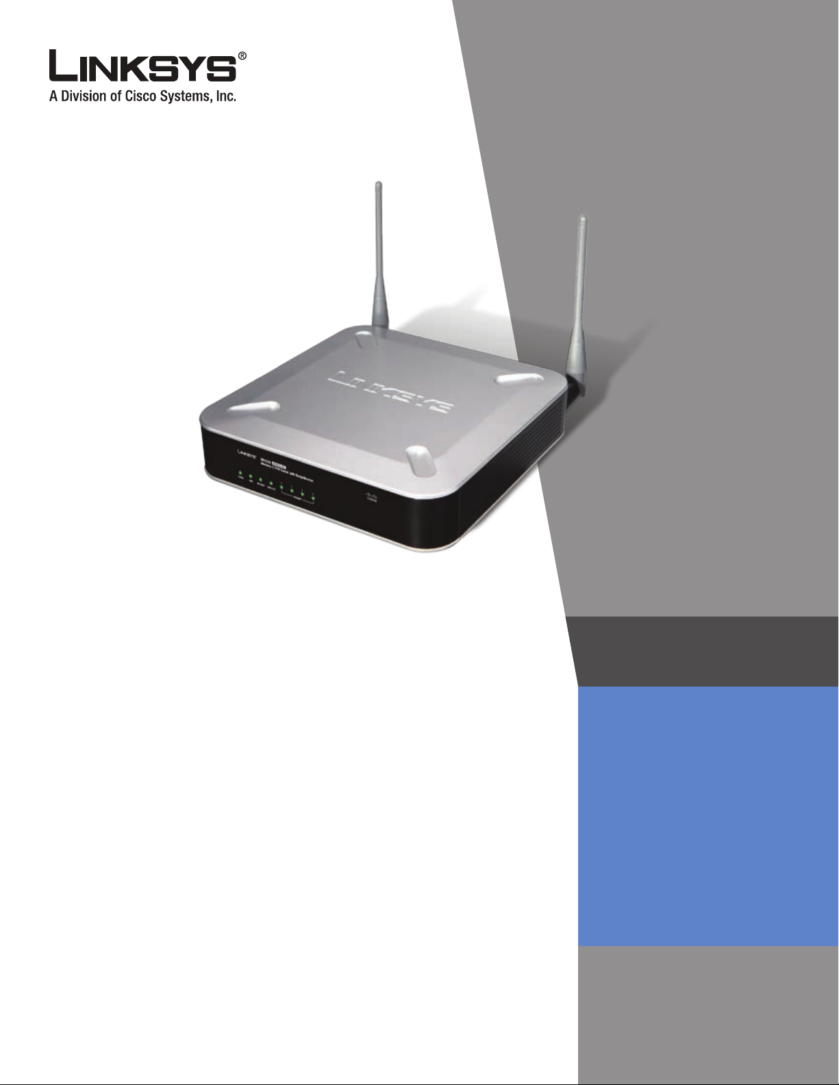
Wireless-G VPN Router
with RangeBooster
USER GUIDE
BUSINESS SERIES
v
Model: WRV200

About This Guide
About This Guide
Icon Descriptions
While reading through the User Guide you may see
various icons that call attention to specific items. Below is
a description of these icons:
NOTE: This check mark indicates that there is
a note of interest and is something that you
should pay special attention to while using the
product.
WARNING: This exclamation point indicates
that there is a caution or warning and it is
something that could damage your property or
product.
WEB: This globe icon indicates a noteworthy
website address or e-mail address.
Open Source
This product may contain material licensed to you under
the GNU General Public License or other open-source
software licenses. Upon request, open-source software
source code is available at cost from Linksys for at least
three years from the product purchase date.
WEB: For detailed license terms and additional
information visit: www.linksys.com/gpl
Online Resources
Website addresses in this document are listed without
http:// in front of the address because most current web
browsers do not require it. If you use an older web browser,
you may have to add http:// in front of the web address.
Resource Website
Linksys www.linksys.com
Linksys International www.linksys.com/international
Glossary www.linksys.com/glossary
Network Security www.linksys.com/security
Copyright and Trademarks
Linksys is a registered trademark or
trademark of Cisco Systems, Inc. and/
or its affiliates in the U.S. and certain
other countries. Copyright © 2007
Cisco Systems, Inc. All rights reserved.
Other brands and product names are
trademarks or registered trademarks
of their respective holders.
Wireless-G VPN Router with RangeBooster
ii

Table of Contents
Chapter 1: Introduction 1
Chapter 2: Planning Your Wireless Network
Network Topology . . . . . . . . . . . . . . . . . . . . . . . . . . . . . . . . . . . . . . . . . . . . . 2
Ad-Hoc versus Infrastructure Mode . . . . . . . . . . . . . . . . . . . . . . . . . . . . . . . . . . 2
Network Layout. . . . . . . . . . . . . . . . . . . . . . . . . . . . . . . . . . . . . . . . . . . . . . . 2
Chapter 3: Planning Your Virtual Private Network (VPN) 3
Why do I need a VPN?. . . . . . . . . . . . . . . . . . . . . . . . . . . . . . . . . . . . . . . . . . . 3
1) MAC Address Spoong . . . . . . . . . . . . . . . . . . . . . . . . . . . . . . . . . . . . . 3
2) Data Sning . . . . . . . . . . . . . . . . . . . . . . . . . . . . . . . . . . . . . . . . . . . . 3
3) Man in the middle attacks. . . . . . . . . . . . . . . . . . . . . . . . . . . . . . . . . . . . 3
What is a VPN? . . . . . . . . . . . . . . . . . . . . . . . . . . . . . . . . . . . . . . . . . . . . . . . 3
VPN Router to VPN Router . . . . . . . . . . . . . . . . . . . . . . . . . . . . . . . . . . . . . 4
Computer (using the Linksys VPN client software) to VPN Router . . . . . . . . . . . . 4
Chapter 4: Product Overview 5
Front Panel. . . . . . . . . . . . . . . . . . . . . . . . . . . . . . . . . . . . . . . . . . . . . . . . . . 5
Back Panel . . . . . . . . . . . . . . . . . . . . . . . . . . . . . . . . . . . . . . . . . . . . . . . . . . 5
Chapter 5: Conguring the Wireless-G VPN Router 6
Overview . . . . . . . . . . . . . . . . . . . . . . . . . . . . . . . . . . . . . . . . . . . . . . . . . . . 6
How to Access the Web-based Utility . . . . . . . . . . . . . . . . . . . . . . . . . . . . . . . . . 7
Setup . . . . . . . . . . . . . . . . . . . . . . . . . . . . . . . . . . . . . . . . . . . . . . . . . . . . . 7
Setup > Basic Settings. . . . . . . . . . . . . . . . . . . . . . . . . . . . . . . . . . . . . . . . 7
Setup > VLAN . . . . . . . . . . . . . . . . . . . . . . . . . . . . . . . . . . . . . . . . . . . . .10
Setup > DDNS. . . . . . . . . . . . . . . . . . . . . . . . . . . . . . . . . . . . . . . . . . . . .10
Setup > MAC Address Clone. . . . . . . . . . . . . . . . . . . . . . . . . . . . . . . . . . . .11
Setup > Advanced Routing . . . . . . . . . . . . . . . . . . . . . . . . . . . . . . . . . . . .12
Wireless. . . . . . . . . . . . . . . . . . . . . . . . . . . . . . . . . . . . . . . . . . . . . . . . . . . .13
Wireless > Basic Wireless Settings . . . . . . . . . . . . . . . . . . . . . . . . . . . . . . . .13
Wireless > Wireless Security . . . . . . . . . . . . . . . . . . . . . . . . . . . . . . . . . . . .13
Wireless > Wireless Network Access . . . . . . . . . . . . . . . . . . . . . . . . . . . . . . .16
Wireless > Advanced Wireless Settings . . . . . . . . . . . . . . . . . . . . . . . . . . . . .17
Wireless > WDS . . . . . . . . . . . . . . . . . . . . . . . . . . . . . . . . . . . . . . . . . . . .17
Firewall . . . . . . . . . . . . . . . . . . . . . . . . . . . . . . . . . . . . . . . . . . . . . . . . . . . .18
Firewall > General . . . . . . . . . . . . . . . . . . . . . . . . . . . . . . . . . . . . . . . . . .18
Firewall > Port Forwarding . . . . . . . . . . . . . . . . . . . . . . . . . . . . . . . . . . . . .18
Firewall > Port Triggering. . . . . . . . . . . . . . . . . . . . . . . . . . . . . . . . . . . . . .19
Firewall > DMZ . . . . . . . . . . . . . . . . . . . . . . . . . . . . . . . . . . . . . . . . . . . .19
Firewall > Access Restriction. . . . . . . . . . . . . . . . . . . . . . . . . . . . . . . . . . . .20
Firewall > URL Filtering . . . . . . . . . . . . . . . . . . . . . . . . . . . . . . . . . . . . . . .20
VPN . . . . . . . . . . . . . . . . . . . . . . . . . . . . . . . . . . . . . . . . . . . . . . . . . . . . . .20
VPN > VPN Client Access . . . . . . . . . . . . . . . . . . . . . . . . . . . . . . . . . . . . . .20
2
Wireless-G VPN Router with RangeBooster
i

Table of Contents
VPN > VPN Passthrough . . . . . . . . . . . . . . . . . . . . . . . . . . . . . . . . . . . . . .21
VPN > IPSec VPN . . . . . . . . . . . . . . . . . . . . . . . . . . . . . . . . . . . . . . . . . . .22
VPN > VPN Summary . . . . . . . . . . . . . . . . . . . . . . . . . . . . . . . . . . . . . . . .24
QoS . . . . . . . . . . . . . . . . . . . . . . . . . . . . . . . . . . . . . . . . . . . . . . . . . . . . . .25
QoS > Application-Based QoS. . . . . . . . . . . . . . . . . . . . . . . . . . . . . . . . . . .25
QoS > Port-Based QoS. . . . . . . . . . . . . . . . . . . . . . . . . . . . . . . . . . . . . . . .25
Administration . . . . . . . . . . . . . . . . . . . . . . . . . . . . . . . . . . . . . . . . . . . . . . .26
Administration > Management . . . . . . . . . . . . . . . . . . . . . . . . . . . . . . . . . .26
Administration > Log . . . . . . . . . . . . . . . . . . . . . . . . . . . . . . . . . . . . . . . .27
Administration > Diagnostics. . . . . . . . . . . . . . . . . . . . . . . . . . . . . . . . . . .28
Administration > Factory Default. . . . . . . . . . . . . . . . . . . . . . . . . . . . . . . . .28
Administration > Firmware Upgrade . . . . . . . . . . . . . . . . . . . . . . . . . . . . . .28
Administration > Reboot . . . . . . . . . . . . . . . . . . . . . . . . . . . . . . . . . . . . . .29
Status . . . . . . . . . . . . . . . . . . . . . . . . . . . . . . . . . . . . . . . . . . . . . . . . . . . . .29
Status > Router . . . . . . . . . . . . . . . . . . . . . . . . . . . . . . . . . . . . . . . . . . . .29
Status > Local Network . . . . . . . . . . . . . . . . . . . . . . . . . . . . . . . . . . . . . . .30
Status > Wireless . . . . . . . . . . . . . . . . . . . . . . . . . . . . . . . . . . . . . . . . . . .30
Status > System Performance . . . . . . . . . . . . . . . . . . . . . . . . . . . . . . . . . . .30
Status > VPN Clients . . . . . . . . . . . . . . . . . . . . . . . . . . . . . . . . . . . . . . . . .31
Appendix A: Troubleshooting 32
Frequently Asked Questions. . . . . . . . . . . . . . . . . . . . . . . . . . . . . . . . . . . . . . .37
Appendix B: Wireless Security Checklist 39
General Network Security Guidelines . . . . . . . . . . . . . . . . . . . . . . . . . . . . . . . . .39
Additional Security Tips . . . . . . . . . . . . . . . . . . . . . . . . . . . . . . . . . . . . . . . . .39
Appendix C:
Overview . . . . . . . . . . . . . . . . . . . . . . . . . . . . . . . . . . . . . . . . . . . . . . . . . . .40
Before You Begin . . . . . . . . . . . . . . . . . . . . . . . . . . . . . . . . . . . . . . . . . . . . . .40
Installing the Linksys QuickVPN Software . . . . . . . . . . . . . . . . . . . . . . . . . . . . . .40
Using the Linksys QuickVPN Software . . . . . . . . . . . . . . . . . . . . . . . . . . . . . . . .41
Distributing Certicates to QuickVPN Users . . . . . . . . . . . . . . . . . . . . . . . . . . . . .42
Appendix D: Conguring
Introduction. . . . . . . . . . . . . . . . . . . . . . . . . . . . . . . . . . . . . . . . . . . . . . . . .43
Environment . . . . . . . . . . . . . . . . . . . . . . . . . . . . . . . . . . . . . . . . . . . . . . . .43
How to Establish a Secure IPSec Tunnel . . . . . . . . . . . . . . . . . . . . . . . . . . . . . . .43
Using Linksys QuickVPN for Windows 2000, XP, or Vista 40
Installing from the CD-ROM . . . . . . . . . . . . . . . . . . . . . . . . . . . . . . . . . . . .40
Downloading and Installing from the Internet . . . . . . . . . . . . . . . . . . . . . . . .40
Version Number of the QuickVPN Client . . . . . . . . . . . . . . . . . . . . . . . . . . . .41
IPSec with a Windows 2000 or XP Computer 43
Step 1: Create an IPSec Policy . . . . . . . . . . . . . . . . . . . . . . . . . . . . . . . . . . .43
Step 2: Build Filter Lists . . . . . . . . . . . . . . . . . . . . . . . . . . . . . . . . . . . . . . .43
Step 3: Congure Individual Tunnel Rules . . . . . . . . . . . . . . . . . . . . . . . . . . .45
Wireless-G VPN Router with RangeBooster
ii

Table of Contents
Step 4: Assign New IPSec Policy. . . . . . . . . . . . . . . . . . . . . . . . . . . . . . . . . .48
Step 5: Create a Tunnel Through the Web-Based Utility . . . . . . . . . . . . . . . . . . .48
Appendix E: Gateway-to-Gateway VPN Tunnel 49
Overview . . . . . . . . . . . . . . . . . . . . . . . . . . . . . . . . . . . . . . . . . . . . . . . . . . .49
Before You Begin . . . . . . . . . . . . . . . . . . . . . . . . . . . . . . . . . . . . . . . . . . . . . .49
Conguration when the Remote Gateway Uses a Static IP Address . . . . . . . . . . . . . .49
Conguration of the WRV200 . . . . . . . . . . . . . . . . . . . . . . . . . . . . . . . . . . .49
Conguration of the RV082 . . . . . . . . . . . . . . . . . . . . . . . . . . . . . . . . . . . .50
Conguration of PC 1 and PC 2 . . . . . . . . . . . . . . . . . . . . . . . . . . . . . . . . . .50
Conguration when the Remote Gateway Uses a Dynamic IP Address. . . . . . . . . . . .51
Conguration of the WRV200 . . . . . . . . . . . . . . . . . . . . . . . . . . . . . . . . . . .51
Conguration of the RV082 . . . . . . . . . . . . . . . . . . . . . . . . . . . . . . . . . . . .51
Conguration of PC 1 and PC 2 . . . . . . . . . . . . . . . . . . . . . . . . . . . . . . . . . .52
Conguration when Both Gateways Use Dynamic IP Addresses . . . . . . . . . . . . . . . .52
Conguration of the WRV200 . . . . . . . . . . . . . . . . . . . . . . . . . . . . . . . . . . .52
Conguration of the RV082 . . . . . . . . . . . . . . . . . . . . . . . . . . . . . . . . . . . .53
Conguration of PC 1 and PC 2 . . . . . . . . . . . . . . . . . . . . . . . . . . . . . . . . . .53
Appendix F: Glossary 54
Appendix G: Specications 5
Appendix H: Warranty Information 5
Exclusions and Limitations. . . . . . . . . . . . . . . . . . . . . . . . . . . . . . . . . . . . . . . .59
Obtaining Warranty Service . . . . . . . . . . . . . . . . . . . . . . . . . . . . . . . . . . . . . . .59
Technical Support . . . . . . . . . . . . . . . . . . . . . . . . . . . . . . . . . . . . . . . . . . . . .60
Appendix I: Regulatory Information 61
FCC Statement . . . . . . . . . . . . . . . . . . . . . . . . . . . . . . . . . . . . . . . . . . . . . . .61
FCC Radiation Exposure Statement . . . . . . . . . . . . . . . . . . . . . . . . . . . . . . . . . .61
Safety Notices. . . . . . . . . . . . . . . . . . . . . . . . . . . . . . . . . . . . . . . . . . . . . . . .61
Industry Canada Statement . . . . . . . . . . . . . . . . . . . . . . . . . . . . . . . . . . . . . . .61
Industry Canada Radiation Exposure Statement: . . . . . . . . . . . . . . . . . . . . . . .61
Avis d’Industrie Canada. . . . . . . . . . . . . . . . . . . . . . . . . . . . . . . . . . . . . . . . . .62
Avis d’Industrie Canada concernant l’exposition aux radiofréquences :. . . . . . . . .62
Wireless Disclaimer . . . . . . . . . . . . . . . . . . . . . . . . . . . . . . . . . . . . . . . . . . . .62
Avis de non-responsabilité concernant les appareils sans l . . . . . . . . . . . . . . . . . .62
User Information for Consumer Products Covered by EU Directive 2002/96/EC on Waste
Electric and Electronic Equipment (WEEE) . . . . . . . . . . . . . . . . . . . . . . . . . . . . . .63
7
9
Appendix J: Contact Information 67
Wireless-G VPN Router with RangeBooster
iii

Chapter 1
Chapter 1: Introduction
Thank you for choosing the Wireless-G VPN Router
with RangeBooster. The WRV200 is a VPN router with a
Wireless-G access point for small offices and home offices.
The 10/100 Ethernet WAN interface connects directly
to your broadband DSL or Cable modem. For the LAN
interface, there is a built-in 4-port, full-duplex 10/100
Ethernet switch that can connect up to four devices.
The wireless AP supports 802.11b/g and incorporates
Linksys RangeBooster technology, which utilizes a MIMO
antennae configuration to provide increased coverage
and reliability over standard 802.11g.
The WRV200 has the advanced security functions needed
for business networking. It has a SPI based firewall with
DoS prevention, but also a Virtual Private Networking
(VPN) engine for secure communication between mobile
or remote workers and branch offices. For your wired and
wireless local area network, there is support for multiple
SSIDs and VLANs for traffic separation. The WRV200’s
Wireless AP implements WPA2-PSK, WPA2-ENT, and WEP
encryption, along with other security features including
enabling/disabling SSID Broadcasts and MAC-based
filtering.
Introduction
Wireless networking in business environments requires
additional flexibility. The WRV200 has the capability to
expand or reduce the area of your wireless network.
There is support for Wireless Distribution System (WDS),
which allows the wireless coverage to be expanded
without wires through wireless bridging between it and
select Linksys stand alone access points. That, along with
the ability to increase or decrease the RF output power,
allows for optimal wireless coverage.
To support VoIP, the WRV200 has a SIP application layer
gateway (ALG) and advanced QoS functionality. SIP based
VoIP data has problems traversing through standard
firewalls with NAT, especially when you deploy multiple SIP
clients. The SIP ALG allows SIP traffic from multiple clients
to pass through the router’s firewall. QoS functionality
can improve the quality of your voice or video over IP.
With support for Wireless QoS (WMM) and wired QoS
(port prioritization), consistent voice and video quality is
maintained throughout your business.
Wireless-G VPN Router with RangeBooster
1
Chapter 2
Networking and Security Basics
Chapter 2: Planning Your Wireless Network
Network Topology
A wireless local area network (WLAN) is exactly like a regular
local area network (LAN), except that each computer in the
WLAN uses a wireless device to connect to the network.
Computers in a WLAN share the same frequency channel
and SSID, which is an identification name shared by the
wireless devices belonging to the same wireless network.
Ad-Hoc versus Infrastructure Mode
Unlike wired networks, wireless networks have two
different modes in which they may be set up: infrastructure
and ad-hoc. An infrastructure configuration is a WLAN
and wired LAN communicating to each other through
an access point. An ad-hoc configuration is wirelessequipped computers communicating directly with each
other. Choosing between these two modes depends on
whether or not the wireless network needs to share data
or peripherals with a wired network or not.
Network Layout
The Wireless-G VPN Router has been specifically designed
for use with both your 802.11b and 802.11g products.
Now, products using these standards can communicate
with each other.
The Wireless-G VPN Router is compatible with all 802.11g
and 802.11n adapters, such as the Notebook Adapters
(WPC4400N, WPC200) for your laptop computers, PCI
Adapter (WMP200) for your desktop PC, and USB Adapter
(WUSB200, USB1000) when you want to enjoy USB
connectivity. The Router will also communicate with
Wireless Ethernet Bridges (WET200).
When you wish to connect your wireless network with
your wired network, you can use the Router’s four LAN
ports. To add more ports, any of the Router’s LAN ports
can be connected to any Linksys Business Series switch
(such as the SLM series or SRW series switches).
With these, and many other, Linksys products, your
networking options are limitless. Go to the Linksys
website at www.linksys.com for more information about
products that work with the Wireless-G VPN Router with
RangeBooster.
If the computers on the wireless network need to be
accessible by a wired network or need to share a peripheral,
such as a printer, with the wired network computers, the
wireless network should be set up in Infrastructure mode.
The basis of Infrastructure mode centers around an access
point or wireless router, such as the Wireless-G VPN Router,
which serves as the main point of communications in
a wireless network. The Router transmits data to PCs
equipped with wireless network adapters, which can
roam within a certain radial range of the Router. You can
arrange the Router and multiple access points to work
in succession to extend the roaming range, and you can
set up your wireless network to communicate with your
Ethernet hardware as well.
If the wireless network is relatively small and needs to
share resources only with the other computers on the
wireless network, then the Ad-Hoc mode can be used.
Ad-Hoc mode allows computers equipped with wireless
transmitters and receivers to communicate directly with
each other, eliminating the need for a wireless router or
access point. The drawback of this mode is that in AdHoc mode, wireless-equipped computers are not able to
communicate with computers on a wired network. And, of
course, communication between the wireless-equipped
computers is limited by the distance and interference
directly between them.
Network Diagram
Wireless-G VPN Router with RangeBooster
2

Chapter 3
Planning Your Virtual Private Network (VPN)
Chapter 3: Planning Your Virtual Private Network (VPN)
Why do I need a VPN?
Computer networking provides a flexibility not available
when using an archaic, paper-based system. With this
flexibility, however, comes an increased risk in security.
This is why firewalls were first introduced. Firewalls help
to protect data inside of a local network. But what do you
do once information is sent outside of your local network,
when e-mails are sent to their destination, or when you
have to connect to your company’s network when you are
out on the road? How is your data protected?
That is when a VPN can help. VPNs are called Virtual Private
Networks because they secure data moving outside of
your network as if it were still within that network.
When data is sent out across the Internet from your
computer, it is always open to attacks. You may already
have a firewall, which will help protect data moving
around or held within your network from being corrupted
or intercepted by entities outside of your network, but
once data moves outside of your network—when you
send data to someone via e-mail or communicate with an
individual over the Internet—the firewall will no longer
protect that data.
At this point, your data becomes open to hackers using
a variety of methods to steal not only the data you are
transmitting but also your network login and security
data. Some of the most common methods are as follows:
1) MAC Address Spoofing
Packets transmitted over a network, either your local
network or the Internet, are preceded by a packet
header. These packet headers contain both the source
and destination information for that packet to transmit
efficiently. A hacker can use this information to spoof
(or fake) a MAC address allowed on the network. With
this spoofed MAC address, the hacker can also intercept
information meant for another user.
2) Data Sniffing
3) Man in the middle attacks
Once the hacker has either sniffed or spoofed enough
information, he can now perform a “man in the middle”
attack. This attack is performed, when data is being
transmitted from one network to another, by rerouting
the data to a new destination. Even though the data is not
received by its intended recipient, it appears that way to
the person sending the data.
These are only a few of the methods hackers use and they
are always developing more. Without the security of your
VPN, your data is constantly open to such attacks as it
travels over the Internet. Data travelling over the Internet
will often pass through many different servers around
the world before reaching its final destination. That is a
long way to go for unsecured data and this is when a VPN
serves its purpose.
What is a VPN?
A VPN, or Virtual Private Network, is a connection between
two endpoints—a VPN Router, for instance—in different
networks that allows private data to be sent securely
over a shared or public network, such as the Internet. This
establishes a private network that can send data securely
between these two locations or networks.
This is done by creating a “tunnel”. A VPN tunnel connects
the two PCs or networks and allows data to be transmitted
over the Internet as if it were still within those networks.
Not a literal tunnel, it is a connection secured by encrypting
the data sent between the two networks.
VPN was created as a cost-effective alternative to using
a private, dedicated, leased line for a private network.
Using industry standard encryption and authentication
techniques—IPSec, short for IP Security—VPN creates a
secure connection that, in effect, operates as if you were
directly connected to your local network. VPN can be used
to create secure networks linking a central office with
branch offices, telecommuters, and/or professionals on
the road (travelers can connect to a VPN Router using any
computer with the Linksys VPN client software.)
There are two basic ways to create a VPN connection:
VPN Router to VPN Router
•
Computer (using the Linksys VPN client software) to
•
VPN Router
Data “sniffing” is a method used by hackers to obtain
network data as it travels through unsecured networks,
such as the Internet. Tools for just this kind of activity,
such as protocol analyzers and network diagnostic tools,
are often built into operating systems and allow the data
to be viewed in clear text.
Wireless-G VPN Router with RangeBooster
IMPORTANT: You must have at least one VPN
Router on one end of the VPN tunnel. At the
other end of the VPN tunnel, you must have
a second VPN Router or a computer with the
Linksys VPN client software.
3
Chapter 3
The VPN Router creates a “tunnel” or channel between two
endpoints, so that data transmissions between them are
secure. A computer with the Linksys VPN client software
can be one of the two endpoints (refer to “Appendix B:
Using Linksys QuickVPN for Windows 2000, XP, or Vista”).
If you choose not to run the VPN client software, any
computer with the built-in IPSec Security Manager
(Microsoft 2000 and XP) allows the VPN Router to create a
VPN tunnel using IPSec (refer to “Appendix C: Configuring
IPSec between a Windows 2000 or XP PC and the Router”).
Other versions of Microsoft operating systems require
additional, third-party VPN client software applications
that support IPSec to be installed.
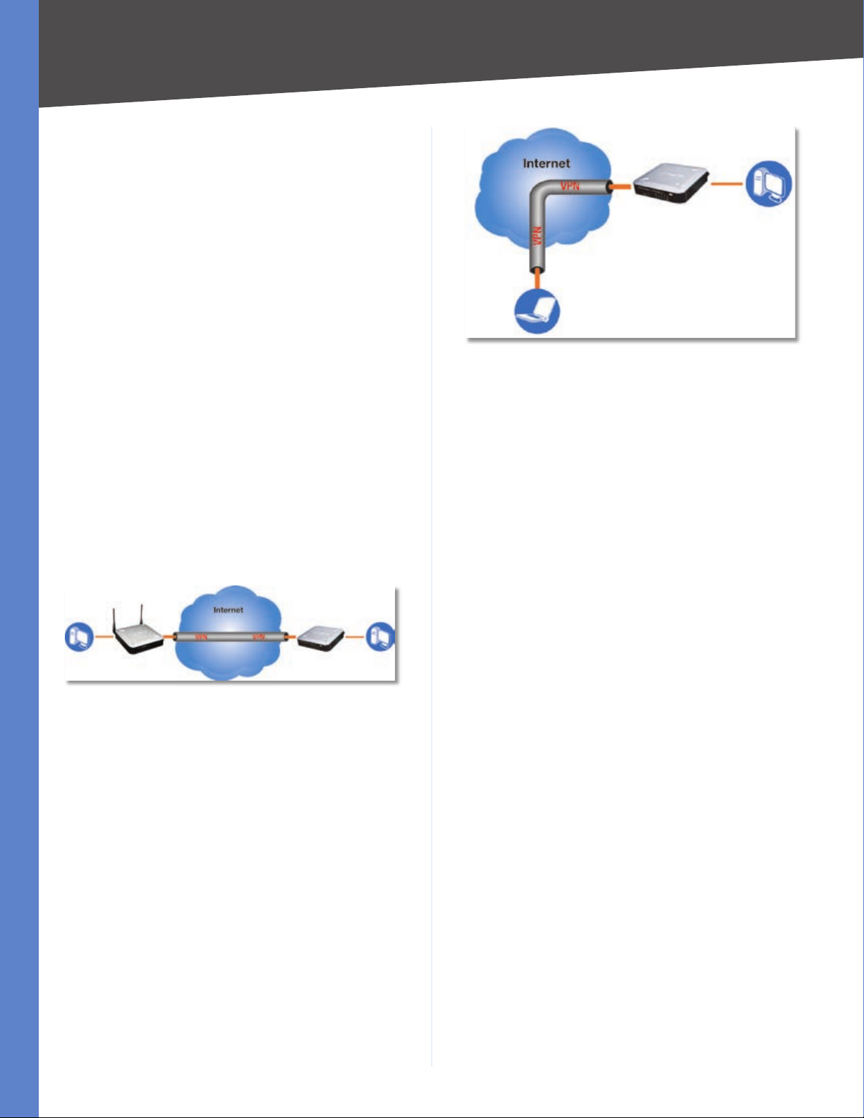
VPN Router to VPN Router
An example of a VPN Router-to-VPN Router VPN would
be as follows. At home, a telecommuter uses his VPN
Router for his always-on Internet connection. His router
is configured with his office’s VPN settings. When he
connects to his office’s router, the two routers create a VPN
tunnel, encrypting and decrypting data. As VPNs utilize
the Internet, distance is not a factor. Using the VPN, the
telecommuter now has a secure connection to the central
office’s network, as if he were physically connected. For
more information, refer to “Appendix D: Configuring a
Gateway-to-Gateway IPSec Tunnel.”
Planning Your Virtual Private Network (VPN)
Office
VPN Router PC 2
Off-Site
Laptop running
Linksys VPN Client Software
Computer to VPN Router
For additional information and instructions about
creating your own VPN, please visit Linksys’s website
at www.linksys.com. You can also refer to “Appendix B:
Using Linksys QuickVPN for Windows 2000, XP, or Vista”,
“Appendix C: Configuring IPSec between a Windows 2000
or XP PC and the Router,” and “Appendix D: Configuring a
Gateway-to-Gateway IPSec Tunnel.”
Home Office
PC 1 WRV200 VPN Router PC 2
VPN Router to VPN Router
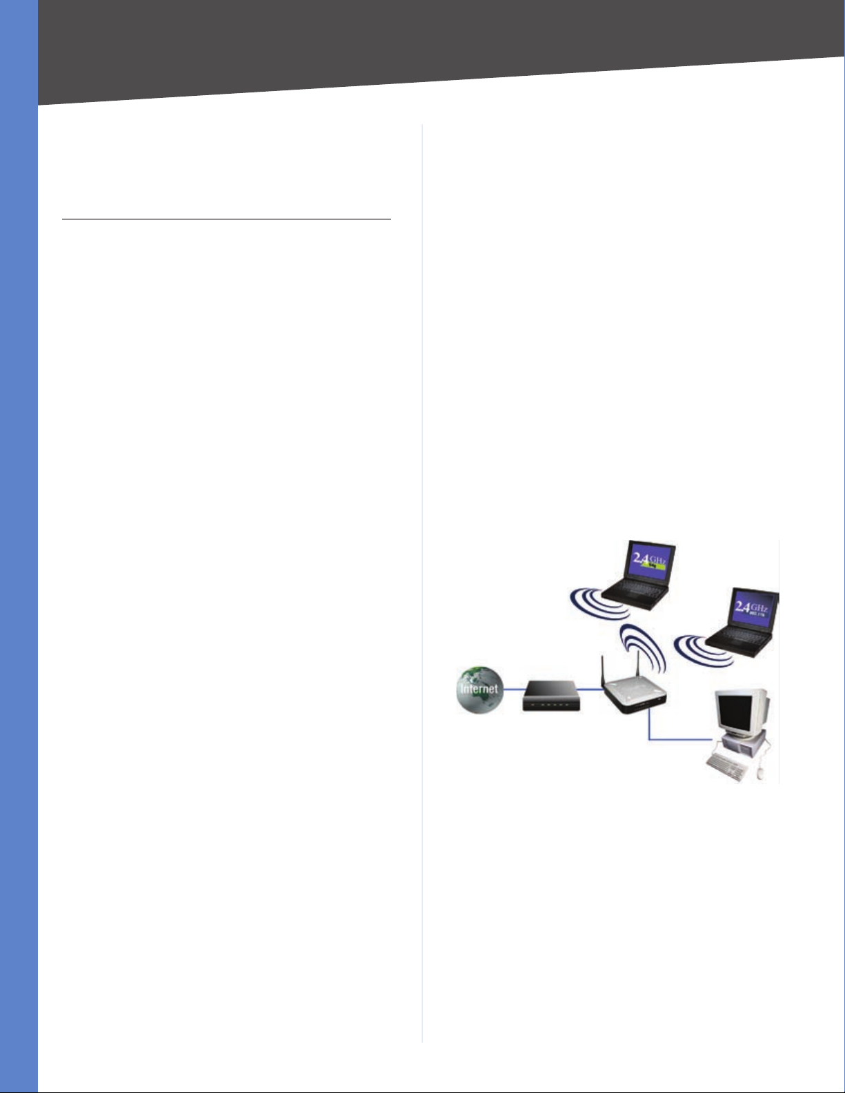
Computer (using the Linksys VPN client software) to VPN Router
The following is an example of a computer-to-VPN Router
VPN. In her hotel room, a traveling businesswoman dials
up her ISP. Her notebook computer has the Linksys VPN
client software, which is configured with her office’s IP
address. She accesses the Linksys VPN client software and
connects to the VPN Router at the central office. As VPNs
utilize the Internet, distance is not a factor. Using the VPN,
she now has a secure connection to the central office’s
network, as if she were physically connected.
Wireless-G VPN Router with RangeBooster
4
Chapter 4
Product Overview
Chapter 4: Product Overview
Front Panel
The Router’s LEDs are located on the front panel of the
Router.
Front Panel
POWER (Green) The Power LED lights up when
the Router is powered on.
DMZ (Green) The DMZ LED lights up when the
Router has an available DMZ port. If the LED is
flashing, the Router is sending or receiving data
over the DMZ port.
INTERNET (Green) The Internet LED lights up
when the Router is connected to your cable or
DSL modem. If the LED is flashing, the Router
is sending or receiving data over the Internet
port.
WIRELESS (Green) The Wireless LED lights
up whenever there is a successful wireless
connection. If the LED is flashing, the Router
is actively sending or receiving data over the
wireless network.
1-4 (ETHERNET) (Green) These four LEDs
correspond to the Router’s four Ethernet
ports. If the LED is continuously lit, the
Router is connected to a device through the
corresponding port (1, 2, 3, or 4). If the LED
is flashing, the Router is actively sending or
receiving data over that port.
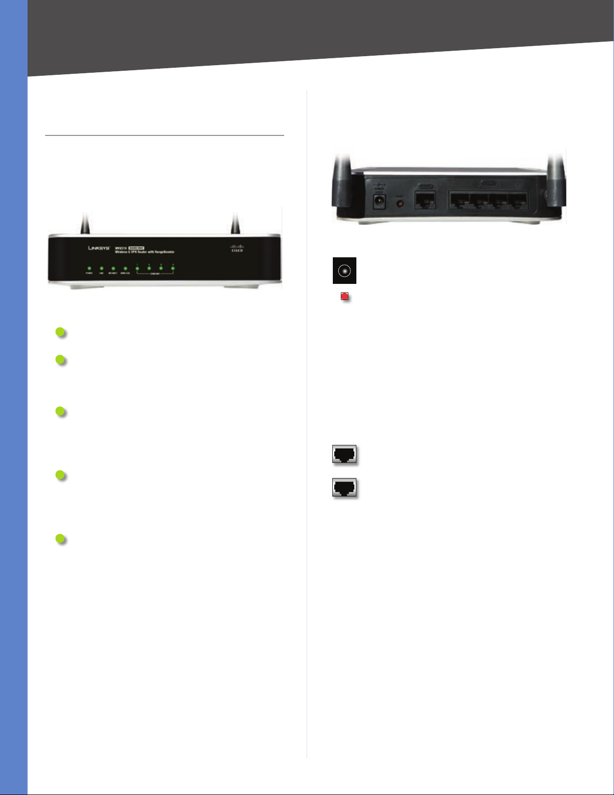
Back Panel
The Router’s ports and Reset button are located on the
back panel of the Router.
Back Panel
POWER The Power port is where you will
connect the AC power cable.
RESET The Reset button has two functions.
If pressed for one second, the Reset
•
button causes a warm reboot—the Router
restarts without losing any of the current
configuration settings.
If pressed for approximately 15 seconds,
•
the Reset button resets the Router’s factory
defaults.
You can also restore the factory defaults
from the Administration > Factory Defaults
screen of the Router’s Web-based Utility.
INTERNET The Internet port connects to your
cable or DSL modem.
1-4 (ETHERNET) The four Ethernet ports
connect to your PCs and other network
devices.
Wireless-G VPN Router with RangeBooster
5

Chapter 5
Chapter 5: Configuring the Wireless-G VPN Router
Overview
Linksys recommends using the Setup CD-ROM for firsttime installation of the Router. If you do not wish to run
the Setup Wizard on the Setup CD-ROM, then follow the
steps in this chapter and use the Router’s Web-based
Utility to configure the Router. For advanced users, you
may configure the Router’s advanced settings through
the Web-based Utility.
This chapter will describe each web page in the Utility and
each page’s key functions. The Utility can be accessed via
your web browser through use of a computer connected
to the Router. For a basic network setup, most users only
have to use the following screens of the Utility:
Basic Setup. On the Basic Setup screen, enter the
•
settings provided by your ISP.
Management. Click the Administration tab and then
•
the Management tab. The Router’s default password
is admin. To secure the Router, change the Password
from its default.
There are seven main tabs: Setup, Wireless, Firewall, VPN,
QoS, Administration, and Status. Additional tabs will be
available after you click one of the main tabs.
Configuring the Wireless-G Router
Advanced Wireless Settings. For advanced users, you
•
can alter data transmission settings on this screen.
WDS. This tab is used for Wireless Distribution System
•
(WDS).
Firewall
General. On this screen, you can configure a variety of
•
filters to enhance the security of your network.
Port Forwarding. To set up public services or other
•
specialized Internet applications on your network,
click this tab.
Port Triggering. To set up triggered ranges and
•
forwarded ranges for Internet applications, click this
tab.
DMZ. Click this tab to allow one local user to be exposed
•
to the Internet for use of special-purpose services.
Access Restriction. This tab allows you to block or
•
allow specific kinds of Internet usage and traffic during
specific days and times.
URL Filtering. This tab allows you to create an URL
•
Filtering policy.
VPN
VPN Client Access. Use this screen to designate VPN
•
clients and their passwords.
VPN Passthrough. This tab is used to allow VPN tunnels
•
to pass through the Router’s firewall using IPSec, L2TP,
or PPTP protocols.
Setup
Basic Setup. Enter the Internet connection and network
•
settings on this screen.
VLAN. The Router provides a port-based VLAN feature.
•
DDNS. On this screen, enable the Router’s Dynamic
•
Domain Name System (DDNS) feature.
MAC Address Clone. If you need to clone a MAC address
•
onto the Router, use this screen.
Advanced Routing. On this screen, configure the
•
dynamic and static routing configuration.
Wireless
Basic Wireless Settings. You can choose your wireless
•
network settings on this screen.
Wireless Security. You can choose your wireless security
•
settings on this screen.
Wireless Network Access. This screen displays your
•
network access list.
Wireless-G VPN Router with RangeBooster
IPSec VPN. The VPN Router creates a tunnel or
•
secure channel between two endpoints, so that
the transmitted data or information between these
endpoints is secure.
VPN Summary. This page summarizes the
•
comprehensive details of IPSec VPN Tunnels.
QoS
Application-based QoS. This involves Internet traffic,
•
which may involve demanding, real-time applications,
such as videoconferencing.
Port-based QoS. This ensures better service to a specific
•
LAN port.
Administration
Management. Alter the Router’s password, its access
•
privileges, SNMP settings, and UPnP settings.
Log. If you want to view or save activity logs, click this
•
tab.
6
Chapter 5
Diagnostics. Use this screen to check the connection
•
between the Router and a PC.
Factory Default. If you want to restore the Router’s
•
factory defaults, then use this screen.
Firmware Upgrade. Click this tab if you want to upgrade
•
the Router’s firmware.
Reboot. Use this to restart the Router.
•
Status
Router. This screen provides status information about
•
the Router.
Local Network. This provides status information about
•
the local network.
Wireless. Status information about the wireless
•
network is displayed here.
System Performance. Status information is provided
•
for all network traffic.
VPN Clients. This screen provides status information
•
about the Router’s VPN clients.
Configuring the Wireless-G Router
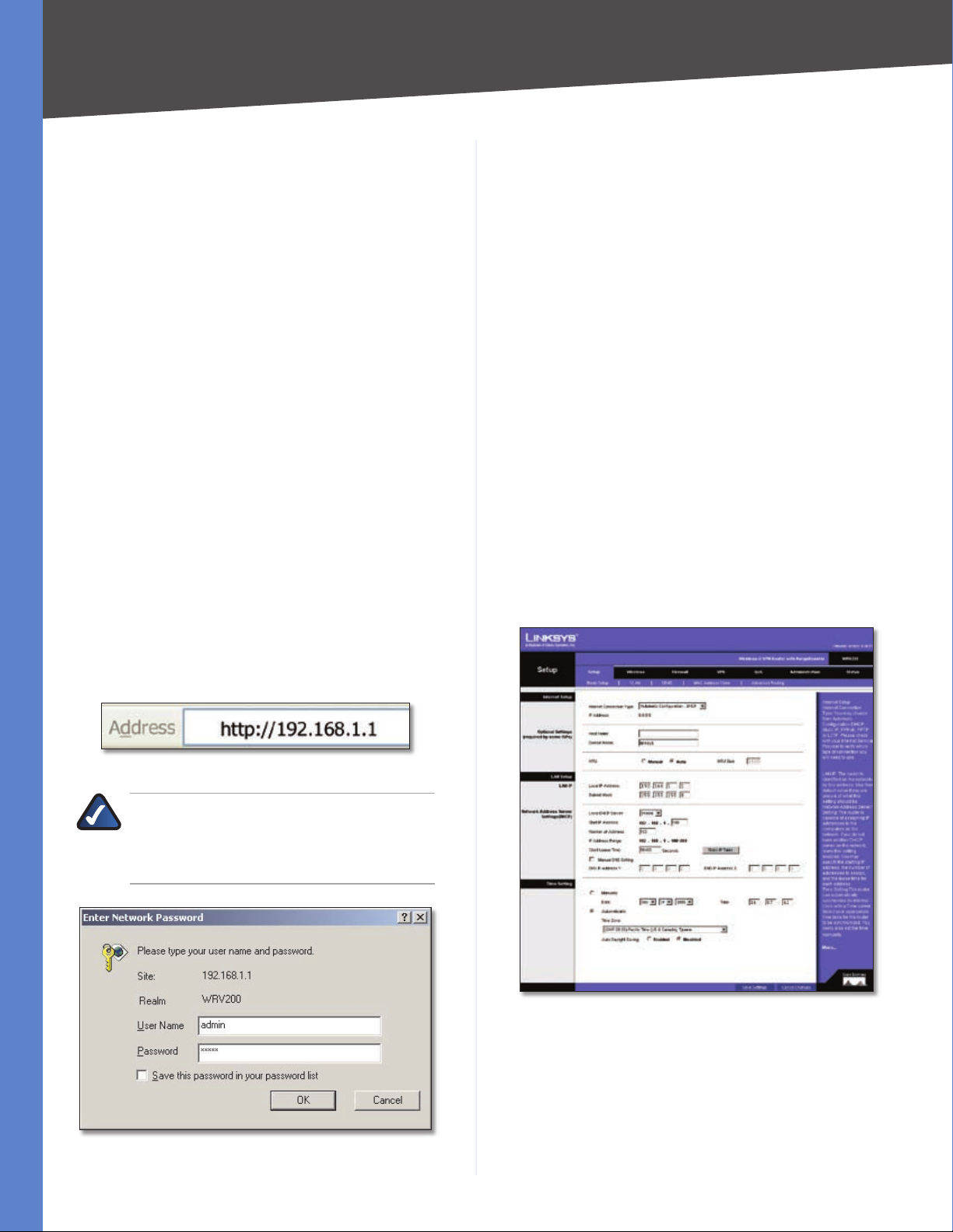
A password request page will appear. (Windows XP users
will see a similar screen.) The first time you open the
web-based utility, enter admin (default user name) in
the User Name field, and enter admin (default password)
in the Password field. Then click OK. You can change the
password later from the Administration > Management
screen.
After you log in, the web-based utility displays the Setup
tab’s Basic Settings screen. Make the necessary changes
through the Utility. When you have finished making
changes to a screen, click Save Settings to save the
changes, or click Cancel Changes to undo your changes.
Help information is shown on the right-hand side of a
screen. For additional information, click More.
The utility’s tabs and screens are described below.
Setup
The Setup tab is used to access all of the Router’s basic
setup functions.
Setup > Basic Settings
How to Access the Web-based Utility
To access the web-based utility, launch Internet Explorer
or Netscape Navigator, and enter the Router’s default
IP address, 192.168.1.1, in the Address field. Then press
Enter.
Address Bar of Web Browser
NOTE: The default IP address is 192.168.1.1. If
the IP address has been changed using DHCP,
enter the assigned IP address instead of the
default.
The first screen that appears is the Basic Setup tab. This
tab allows you to change the Router’s general settings.
Setup > Basic Settings - Automatic Configuration - DHCP
Password Request
Wireless-G VPN Router with RangeBooster
Internet Setup
The Internet Setup section configures the Router for
your Internet connection type. This information can be
obtained from your ISP.
Internet Connection Type The Router supports six types
of connections. Each Setup > Basic Settings screen and
7
Chapter 5
available features will differ depending on what kind of
connection type you select. The connection types are:
Automatic Configuration - DHCP
•
Static IP
•
PPPoE
•
PPTP
•
L2TP
•
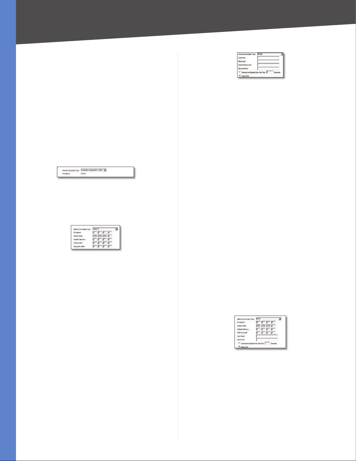
Automatic Configuration - DHCP
By default, the Router’s Configuration Type is set to
Automatic Configuration - DHCP, and it should be kept
only if your ISP supports DHCP or you are connecting
through a dynamic IP address.
Automatic Configuration - DHCP
Static IP
If your connection uses a permanent IP address to connect
to the Internet, then select Static IP.
Static IP
IP Address This is the Router’s IP address, when seen
from the WAN, or the Internet. Your ISP will provide you
with the IP Address you need to specify here.
Subnet Mask This is the Router’s Subnet Mask, as seen
by external users on the Internet (including your ISP). Your
ISP will provide you with the Subnet Mask.
Default Gateway Your ISP will provide you with the
Default Gateway Address, which is the ISP server’s IP
address.
Configuring the Wireless-G Router
PPPoE
User Name and Password/Confirm Password Enter
the User Name and Password provided by your ISP. Then,
enter the password again to confirm it.
Service Name This is required by some service providers.
If your service provider has given you this information,
enter it in this field. If you are not sure if your service
provider requires this information, or if you do not know
the service name, leave this field blank.
Connect on Demand: Max Idle Time You can configure
the Router to cut the Internet connection after it has been
inactive for a specified period of time (Max Idle Time), and
then automatically re-establish the connection as soon
as you attempt to access the Internet again. To activate
Connect on Demand, select the Connect on Demand
option and enter in the Max Idle Time field the number of
seconds of inactivity that must elapse before your Internet
connection is terminated automatically.
Keep Alive If you select this option, the Router will
periodically check your Internet connection. If you are
disconnected, then the Router will automatically reestablish your connection. To use this option, click the
radio button next to Keep Alive.
When you have finished making changes to the screen,
click Save Settings to save the changes, or click Cancel
Changes to undo your changes.
PPTP
Point-to-Point Tunneling Protocol (PPTP) is a service that
applies to connections in Europe and Israel only.
Primary DNS (Required) and Secondary DNS
(Optional) Your ISP will provide you with at least one
DNS (Domain Name System) Server IP Address.
When you have finished making changes to the screen,
click Save Settings to save the changes, or click Cancel
Changes to undo your changes.
PPPoE
Some DSL-based ISPs use PPPoE (Point-to-Point Protocol
over Ethernet) to establish Internet connections. If you are
connected to the Internet through a DSL line, check with
your ISP to see if they use PPPoE. If they do, you will have
to enable PPPoE.
Wireless-G VPN Router with RangeBooster
PPTP
IP Address This is the Router’s IP address, when seen
from the WAN, or the Internet. Your ISP will provide you
with the IP Address you need to specify here.
Subnet Mask This is the Router’s Subnet Mask, as seen
by external users on the Internet (including your ISP). Your
ISP will provide you with the Subnet Mask.
Default Gateway Your ISP will provide you with the
Default Gateway Address.
PPTP Server IP Enter the IP address of the PPTP server.
8
Chapter 5
Configuring the Wireless-G Router
User Name and Password Enter the User Name and
Password provided by your ISP.
Connect on Demand: Max Idle Time You can configure
the Router to cut the Internet connection after it has been
inactive for a specified period of time (Max Idle Time), and
then automatically re-establish the connection as soon
as you attempt to access the Internet again. To activate
Connect on Demand, select the Connect on Demand
option and enter in the Max Idle Time field the number of
seconds of inactivity that must elapse before your Internet
connection is terminated automatically.
Keep Alive If you select this option, the Router will
periodically check your Internet connection. If you are
disconnected, then the Router will automatically reestablish your connection. To use this option, click the
radio button next to Keep Alive.
When you have finished making changes to the screen,
click Save Settings to save the changes, or click Cancel
Changes to undo your changes.
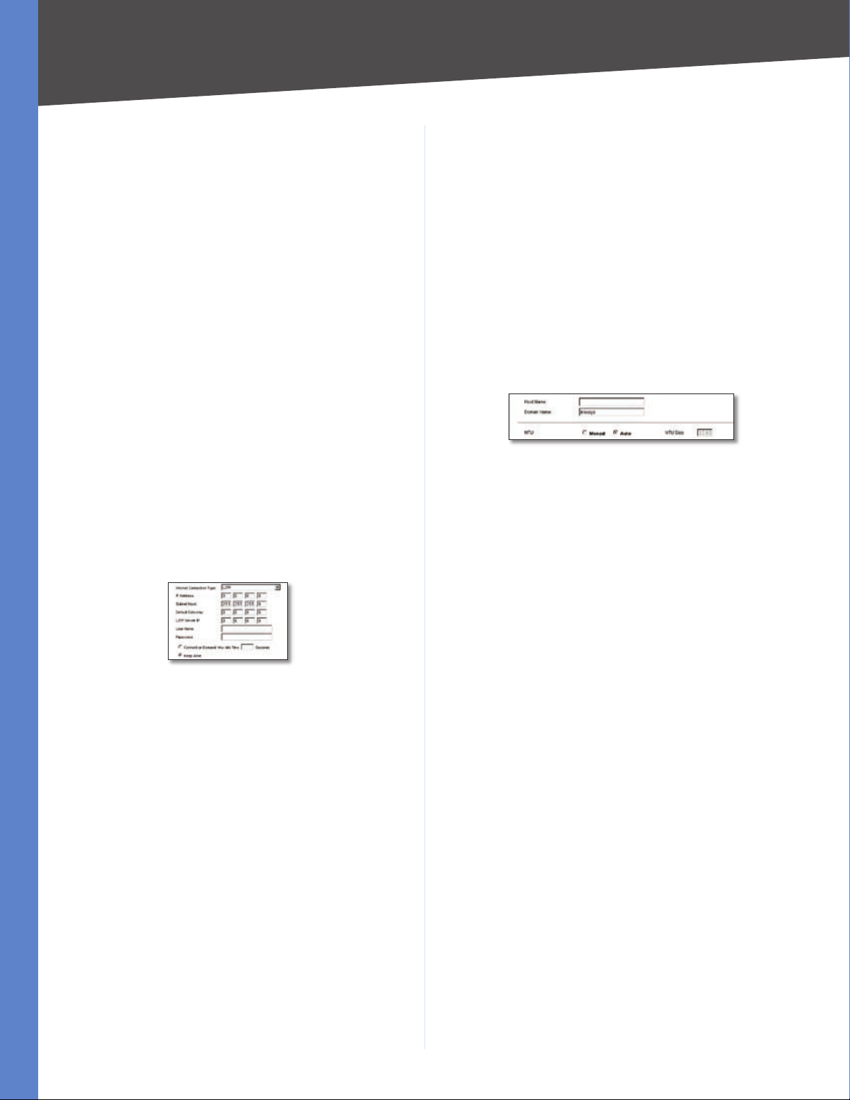
L2TP
Layer 2 Tunneling Protocol (L2TP) is a service that tunnels
Point-to-Point Protocol (PPP) across the Internet. It is used
mostly in European countries. Check with your ISP for the
necessary setup information.
seconds of inactivity that must elapse before your Internet
connection is terminated automatically.
Keep Alive If you select this option, the Router will
periodically check your Internet connection. If you are
disconnected, then the Router will automatically reestablish your connection. To use this option, click the
radio button next to Keep Alive.
When you have finished making changes to the screen,
click Save Settings to save the changes, or click Cancel
Changes to undo your changes.
Optional Settings (Required by some ISPs)
Some of these settings may be required by your ISP. Verify
with your ISP before making any changes.
Optional Settings
Host Name and Domain Name These fields allow you
to supply a host and domain name for the Router. Some
ISPs require these names as identification. You may have
to check with your ISP to see if your broadband Internet
service has been configured with a host and domain
name. In most cases, leaving these fields blank will work.
L2TP
IP Address This is the Router’s IP address, when seen
from the WAN, or the Internet. Your ISP will provide you
with the IP Address you need to specify here.
Subnet Mask This is the Router’s Subnet Mask, as seen
by external users on the Internet (including your ISP). Your
ISP will provide you with the Subnet Mask.
Default Gateway Your ISP will provide you with the
Default Gateway Address.
L2TP Server IP Enter the IP address of the L2TP server.
User Name and Password Enter the User Name and
Password provided by your ISP.
Connect on Demand: Max Idle Time You can configure
the Router to cut the Internet connection after it has been
inactive for a specified period of time (Max Idle Time), and
then automatically re-establish the connection as soon
as you attempt to access the Internet again. To activate
Connect on Demand, select the Connect on Demand
option and enter in the Max Idle Time field the number of
MTU The MTU (Maximum Transmission Unit) setting
specifies the largest packet size permitted for network
transmission. Select Manual and enter the value desired.
It is recommended that you leave this value in the 1200
to 1500 range. For most DSL users, it is recommended to
use the value 1492. By default, MTU is set at 1500 when
disabled.
MTU Size When Manual is selected in the MTU field, this
option is enabled. It is recommended that you set this
value within the range of 1200 to 1500, but the value can
be defined between 128 and 1500.
LAN Setup
The LAN Setup section allows you to change the Router’s
local network settings.
LAN IP
The Router’s Local IP Address and Subnet Mask are shown
here. In most cases, you can keep the defaults.
Local IP Address The default value is 192.168.1.1.
Subnet Mask The default value is 255.255.255.0.
Network Address Server Settings (DHCP)
The Router can be used as your network’s DHCP (Dynamic
Host Configuration Protocol) server, which automatically
Wireless-G VPN Router with RangeBooster
9
Chapter 5
Configuring the Wireless-G Router
assigns an IP address to each PC on your network. Unless
you already have one, it is highly recommended that you
leave the Router enabled as a DHCP server.
Local DHCP Server DHCP is already enabled by factory
default. If you already have a DHCP server on your network,
set the Router’s DHCP option to Disabled. If you disable
DHCP, assign a static IP address to the Router.
Start IP Address Enter a value for the DHCP server to
start with when issuing IP addresses. This value must be
192.168.1. 2 or greater, but smaller than 192.168.1.254,
because the default IP address for the Router is 192.168.1.1,
and 192.168.1.255 is the broadcast IP address.
Number of Address Enter the maximum number of PCs
that you want the DHCP server to assign IP addresses
to. This number cannot be greater than 253. In order to
determine the DHCP IP Address range, add the starting IP
address (e.g., 100) to the number of DHCP users.
IP Address Range The range of DHCP addresses is
displayed here.
Client Lease Time This is the amount of time a DHCP
client can keep the assigned IP address before it sends a
renewal request to the DHCP server.
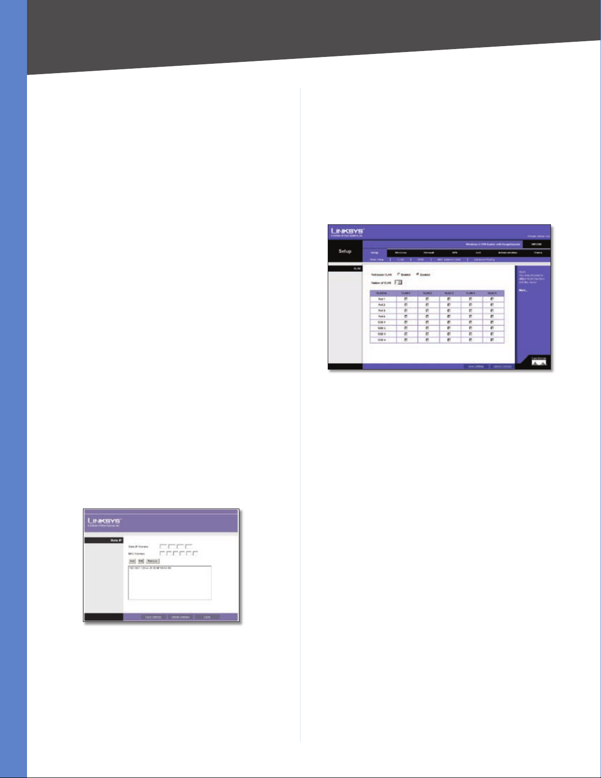
The Static IP Table shows the mapping of MAC addresses
to IP addresses. To use this feature, click Static IP Table,
then enter the Static IP Address and MAC address in the
fields, then click Add. To edit an entry, highlight the entry
in the table, click Edit, make your changes in the fields,
then click Add. To remove an entry, highlight the entry,
then click Remove.
Manual DNS Setting To enter the DNS IP addresses
manually, check the box, then enter up to two IP addresses
in the fields provided.
Automatically Select your time zone from the Time Zone
drop-down menu. If you want to enable the Auto Daylight
Savings feature, click Enabled.
When you have finished making changes to the screen,
click Save Settings to save the changes, or click Cancel
Changes to undo your changes.
Setup > VLAN
The Setup > VLAN screen allows you to use the Router’s
port-based VLAN feature.
Setup > VLAN
Port-based VLAN Select Enabled to enable the feature.
When enabled, and a VLAN is selected, VLAN1 will be
enabled as a default VLAN, so you will have two VLANs.
Select Disabled to disable the feature. When this feature
is disabled, all LAN ports are on the same LAN.
Number of VLAN Select the number of the VLAN from
the drop-down menu.
VLAN No. Select the VLAN number to associate with the
desired port.
Static IP Table
Time Settings
This is where you set the time for the Router. You can set
the time and date manually or automatically.
Manually Select the date from the Date drop-down
menus. Then enter the time in the Time fields.
Wireless-G VPN Router with RangeBooster
When you have finished making changes to the screen,
click Save Settings to save the changes, or click Cancel
Changes to undo your changes.
Setup > DDNS
The Router offers a Dynamic Domain Name System (DDNS)
feature. DDNS lets you assign a fixed host and domain
name to a dynamic Internet IP address. It is useful when
you are hosting your own website, FTP server, or other
server behind the Router and your ISP does not give you
a fixed IP address.
Before you can use this feature, you need to sign up for
DDNS service at one of two DDNS service providers,
DynDNS.org or TZO.com.
10
Chapter 5
Configuring the Wireless-G Router
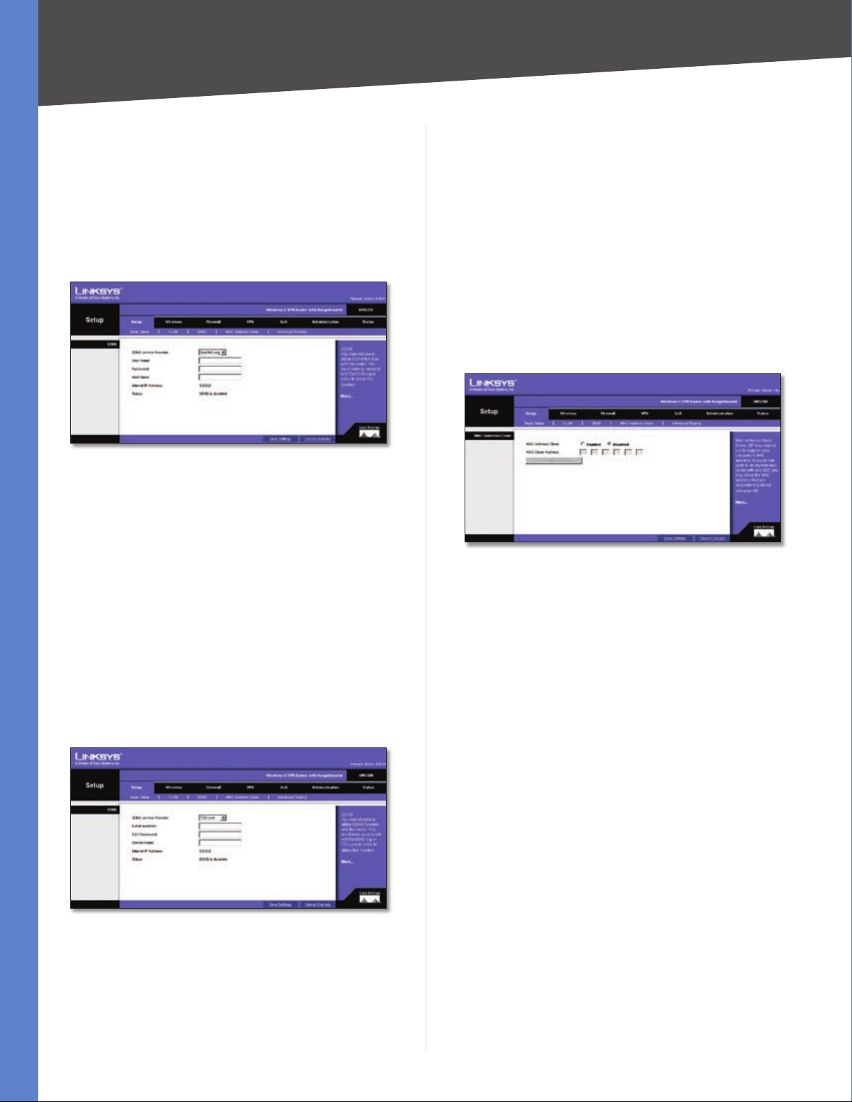
DDNS
If your DDNS service is provided by DynDNS.org, then
select DynDNS.org in the drop-down menu. If your DDNS
service is provided by TZO, then select TZO.com. The
features available on the DDNS screen will vary, depending
on which DDNS service provider you use.
DynDNS.org
Setup > DDNS - DynDNS
User Name, Password, and Host Name Enter the User
Name, Password, and Host Name of the account you set
up with DynDNS.org.
Status The status of the DDNS service connection is
displayed here.
When you have finished making changes to the screen,
click Save Settings to save the changes, or click Cancel
Changes to undo your changes.
Setup > MAC Address Clone
Some ISPs require that you register a MAC address. This
feature “clones” your network adapter’s MAC address onto
the Router, and prevents you from having to call your ISP
to change the registered MAC address to the Router’s
MAC address. The Router’s MAC address is a 12-digit code
assigned to a unique piece of hardware for identification.
Internet IP Address The Router’s current Internet IP
Address is displayed here. Because it is dynamic, it will
change.
Status The status of the DDNS service connection is
displayed here.
When you have finished making changes to the screen,
click Save Settings to save the changes, or click Cancel
Changes to undo your changes. For help information,
click More.
TZO.com
Setup > DDNS - TZO
Setup > MAC Address Clone
MAC Address Clone To use MAC address cloning, select
Enabled.
MAC Clone Address Enter the MAC Address registered
with your ISP in this field.
Clone My MAC Address If you want to clone the MAC
address of the PC you are currently using to configure the
Router, then click Clone My MAC Address. The Router
will automatically detect your PC’s MAC address, so you
do not have to call your ISP to change the registered MAC
address to the Router’s MAC address. It is recommended
to use the PC registered with the ISP for this operation.
When you have finished making changes to the screen,
click Save Settings to save the changes, or click Cancel
Changes to undo your changes. For help information,
click More.
Email, TZO Password Key, and Domain Name Enter the
Email Address, TZO Password Key, and Domain Name of
the service you set up with TZO.
Internet IP Address The Router’s current Internet IP
Address is displayed here. Because it is dynamic, this will
change.
Wireless-G VPN Router with RangeBooster
11
Chapter 5
Configuring the Wireless-G Router
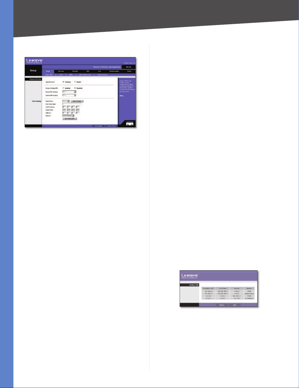
Setup > Advanced Routing
Setup > Advanced Routing
The Setup > Advanced Routing screen allows you to
configure the dynamic and static routing settings.
Operation Mode Select Gateway or Router from the
drop-down menu. If this Router is hosting your network’s
connection to the Internet, keep the default, Gateway,
which will also enable NAT. If you have a different router
hosting your Internet connection, then select Router.
Dynamic Routing
With Dynamic Routing you can enable the Router to
automatically adjust to physical changes in the network’s
layout. The Router, using the RIP protocol, determines
the network packets’ route based on the fewest number
of hops between the source and the destination. The RIP
protocol regularly broadcasts routing information to other
routers on the network.
Dynamic Routing (RIP) To use dynamic routing, click the
Enabled radio button.
Receive RIP Versions To use dynamic routing for
reception of network data, select the protocol you want:
RIPv1 or RIPv2.
Delete This Entry If you need to delete a route, select its
number from the drop-down menu, and click Delete This
Entry.
Enter Router Name Enter the name of your Router.
LAN IP Address The LAN IP Address is the address of the
remote network or host to which you want to assign a
static route. Enter the IP address of the host for which you
wish to create a static route. If you are building a route to
an entire network, be sure that the network portion of the
IP address is set to 0. For example, the Router’s standard IP
address is 192.168.1.1. Based on this address, the address
of the routed network is 192.168.1, with the last digit
determining the Router’s place on the network. Therefore
you would enter the IP address 192.168.1.0 if you wanted
to route to the Router’s entire network, rather than just to
the Router.
Subnet Mask The Subnet Mask (also known as the
Network Mask) determines which portion of an IP address
is the network portion, and which portion is the host
portion. Take, for example, a network in which the Subnet
Mask is 255.255.255.0. This determines (by using the values
255) that the first three numbers of a network IP address
identify this particular network, while the last digit (from 1
to 254) identifies the specific host.
Gateway Enter the IP address of the gateway device that
allows for contact between the Router and the remote
network or host.
Interface Select LAN & Wireless or Internet, depending
on the location of the static route’s final destination.
Show Routing Table Click the Show Routing Table
button to open a screen displaying how packets are
routed through your local network. For each route, the
Destination LAN IP address, Subnet Mask, Gateway, and
Interface are displayed. Click Refresh to update the
information. Click Close to exit this screen.
Transmit RIP Versions To use dynamic routing for
transmission of network data, select the protocol you
want: RIPv1 or RIPv2.
Static Routing
If the Router is connected to more than one network,
you can configure static routes to direct packets to the
destination network (A static route is a pre-determined
pathway that a packet must travel to reach a specific host
or network.) To create a static route, change the following
settings:
Route Entries Select the number of the static route from
the drop-down menu. The Router supports up to 5 static
route entries.
Wireless-G VPN Router with RangeBooster
Setup > Advanced Routing
When you have finished making changes to the screen,
click Save Settings to save the changes, or click Cancel
Changes to undo your changes. For help information,
click More.
12
Chapter 5
Configuring the Wireless-G Router
Wireless
The Wireless tab is used to configure the Router’s wireless
network settings.
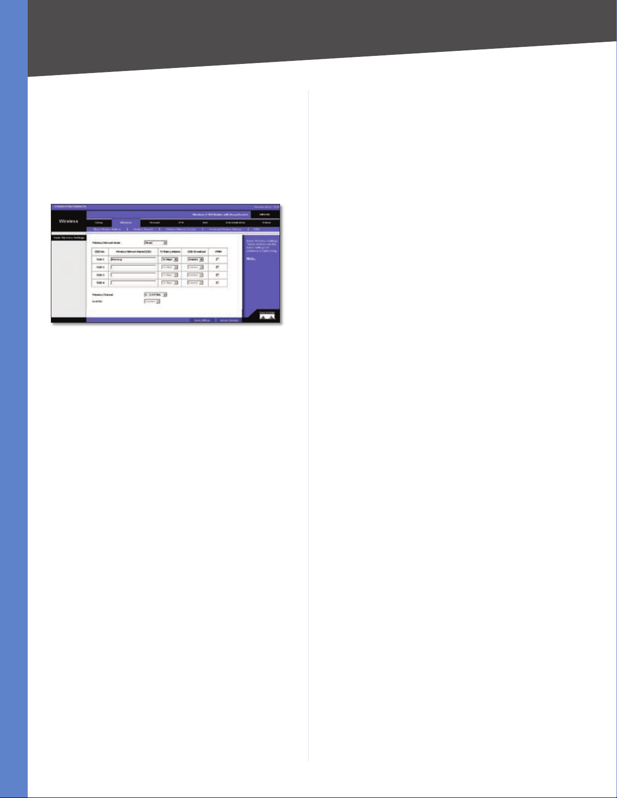
Wireless > Basic Wireless Settings
The basic settings for wireless networking are configured
on this screen.
Wireless > Basic Wireless Settings
Wireless Network Mode
Wireless Network Mode From this drop-down menu,
you can select the wireless standards running on your
network. If you have both 802.11g and 802.11b devices
in your network, keep the default setting, Mixed. If you
have only 802.11g devices, select G-Only. If you have
only 802.11b devices, select B-Only. If you do not have
any 802.11g and 802.11b devices in your network, select
Disable.
Wireless Network Name (SSID) The SSID is the network
name shared among all points in a wireless network.
The SSID must be identical for all devices in the wireless
network. It is case-sensitive and must not exceed 32
characters (use any of the characters on the keyboard).
Make sure this setting is the same for all points in your
wireless network. For added security, you should change
the default SSID (linksys-g) to a unique name.
TX Rate Limitation The rate of data transmission should
be set depending on the speed of your wireless network.
You can select from a range of transmission speeds and
the Router will negotiate the connection speed between
the Router and a wireless client by this rate.
Wireless SSID Broadcast When wireless clients survey
the local area for wireless networks to associate with, they
will detect the SSID broadcast by the Router. To broadcast
the Router’s SSID, keep the default setting, Enable. If you
do not want to broadcast the Router’s SSID, then select
Disabled.
It specifically supports priority tagging and queuing. Click
the WMM check box to enable WMM.
Wireless Channel Select the appropriate channel from
the drop-down menu. All devices in your wireless network
must transmit using the same channel in order to function
correctly. You may need to change the wireless channel to
improve the communication quality.
U-APSD The Unscheduled Automatic Power Save Delivery
(U-APSD) feature is an enhanced power-save mode. Select
Enable to allow the Router to enter power-save mode.
When you have finished making changes to the screen,
click Save Settings to save the changes, or click Cancel
Changes to undo your changes. For help information,
click More.
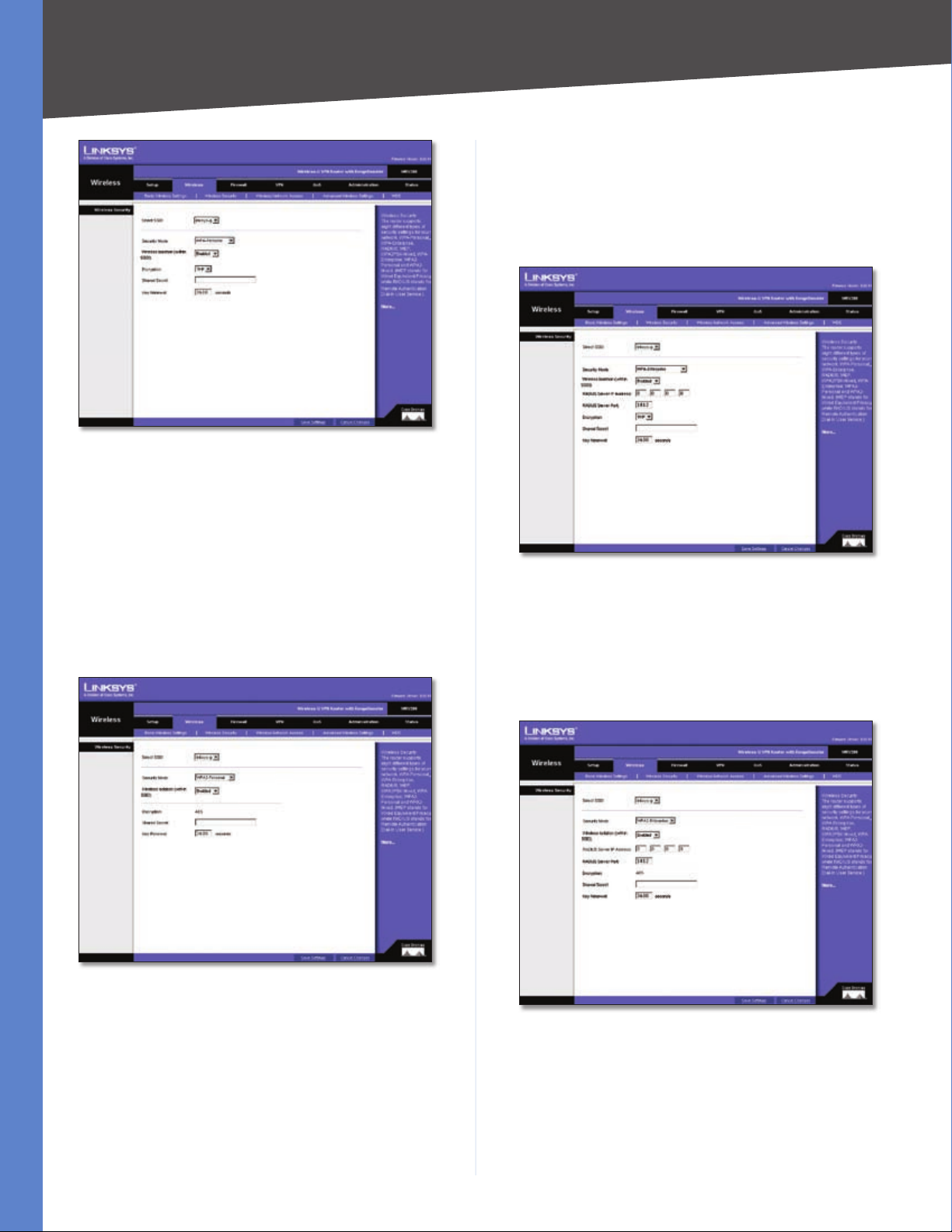
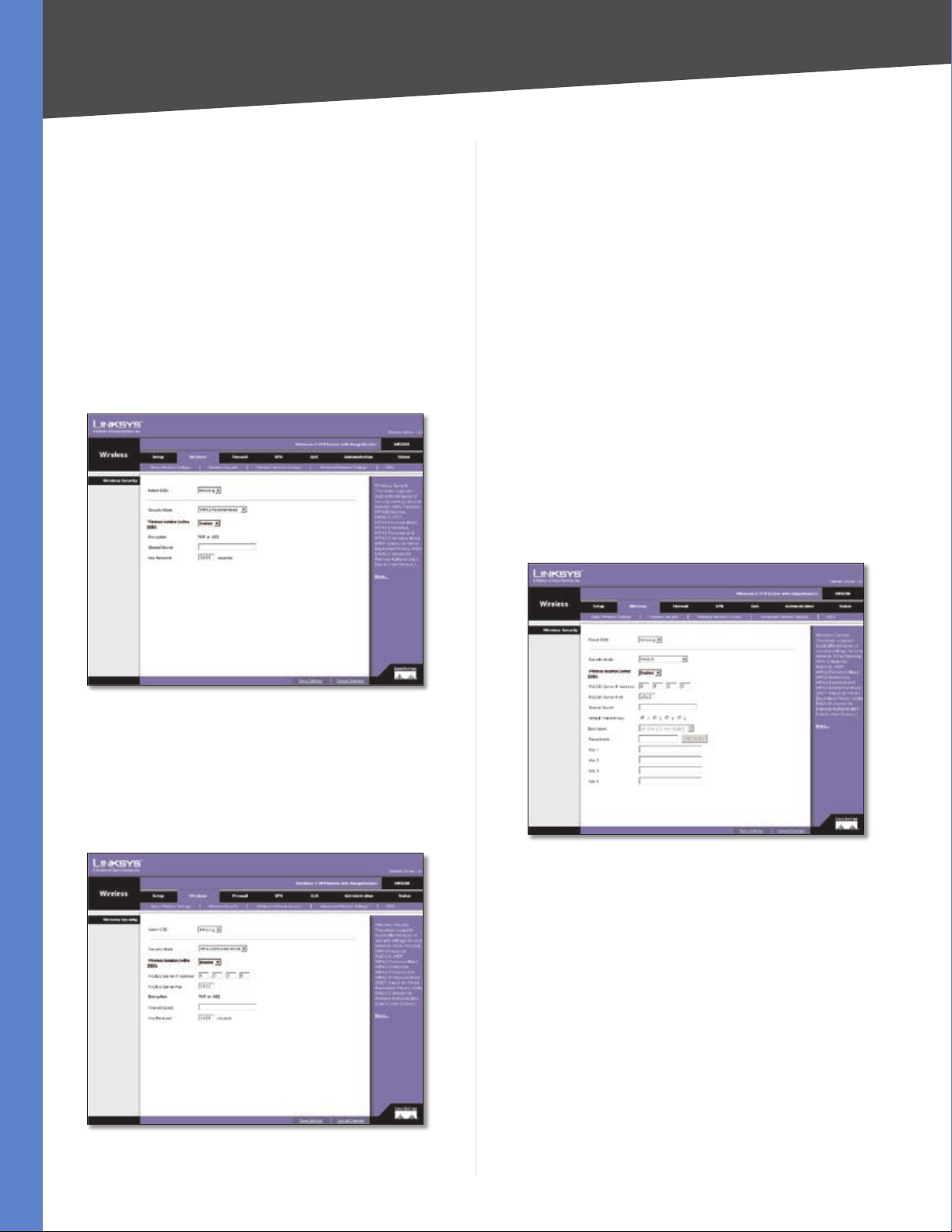
Wireless > Wireless Security
The Wireless Security settings configure the security of
your wireless network. There are eight wireless security
mode options supported by the Router: WPA-Personal,
WPA2-Personal, WPA Enterprise, WPA2 Enterprise, WPA2Personal-Mixed, WPA2-Enterprise Mixed, RADIUS, and
WEP. (WPA stands for Wi-Fi Protected Access, which is a
security standard stronger than WEP encryption. WEP
stands for Wired Equivalent Privacy, while RADIUS stands
for Remote Authentication Dial-In User Service.) For
detailed instructions on configuring wireless security for
the Router, turn to “Appendix B: Wireless Security.”
Select SSID Select the SSID that you want to apply the
wireless security settings to.
Security Mode Select the appropriate security mode for
your network; all devices on your network must use the
same security mode and settings to work correctly.
Wireless isolation within SSID This feature is disabled
by default. Wireless PCs that are associated with the same
SSID can see and transfer files between each other. If
you enable this feature, wireless PCs will not be able to
see each other. This is useful when setting up a wireless
hotspot location.
WPA Personal
WPA gives you two encryption methods with dynamic
encryption keys. Select TKIP or AES from the Encryption
drop-down menu. Enter a Shared Secret (Pre-Shared Key)
of 8-32 characters. Then enter the Key Renewal period,
which instructs the Router how often it should change the
encryption keys.
WMM WMM (Wi-Fi Multimedia) is a component of the IEEE
802.11e wireless LAN standard for quality of service (QoS).
Wireless-G VPN Router with RangeBooster
13
Chapter 5
Wireless Security - WPA Personal
When you have finished making changes to the screen,
click Save Settings to save the changes, or click Cancel
Changes to undo your changes. For help information,
click More.
Configuring the Wireless-G Router
server’s IP address. Select TKIP or AES from the WPA
Algorithms drop-down menu. Enter the RADIUS server’s
port number, along with the Shared Secret key, which is
the key shared between the Router and the server. Last,
enter the Key Renewal period, which instructs the Router
how often it should change the encryption keys.
WPA2 Personal
WPA2 gives you the encryption method AES. Enter a
Shared Secret of 8-32 characters. Then enter the Key
Renewal period, which instructs the Router how often it
should change the encryption keys.
Wireless Security - WPA2 Personal
When you have finished making changes to the screen,
click Save Settings to save the changes, or click Cancel
Changes to undo your changes. For help information,
click More.
WPA Enterprise
This option features WPA used in coordination with a
RADIUS server. (This should only be used when a RADIUS
server is connected to the Router.) Enter the RADIUS
Wireless Security - WPA Enterprise
When you have finished making changes to the screen,
click Save Settings to save the changes, or click Cancel
Changes to undo your changes. For help information,
click More.
WPA2 Enterprise
Wireless Security - WPA2 Enterprise
This option features WPA2 used in coordination with a
RADIUS server. (This should only be used when a RADIUS
server is connected to the Router.) Enter the RADIUS
server’s IP address. Enter the RADIUS server’s port number,
along with the Shared Secret key, which is the key shared
between the Router and the server. Last, enter the Key
Wireless-G VPN Router with RangeBooster
14
Chapter 5
Configuring the Wireless-G Router
Renewal period, which instructs the Router how often it
should change the encryption keys.
When you have finished making changes to the screen,
click Save Settings to save the changes, or click Cancel
Changes to undo your changes. For help information,
click More.
WPA2 Personal Mixed
WPA2 Personal Mixed gives you either WPA-Personal
(TKIP) or PSK2 (AES) encryption. Enter a Shared Secret of
8-63 characters. Then enter a Key Renewal period, which
instructs the Router how often it should change the
encryption keys.
This option features WPA2 used in coordination with a
RADIUS server. (This should only be used when a RADIUS
server is connected to the Router.) Enter the RADIUS
server’s IP address and port number, along with the shared
secret (authentication key) shared by the Router and the
server. Last, enter the Key Renewal period, which instructs
the Router how often it should change the encryption
keys.
When you have finished making changes to the screen,
click Save Settings to save the changes, or click Cancel
Changes to undo your changes. For help information,
click More.
RADIUS
This option features WEP used in coordination with a
RADIUS server. (This should only be used when a RADIUS
server is connected to the Router.) First, enter the RADIUS
server’s IP address and port number in the RADIUS Server
IP Address and RADIUS Server Port fields. Enter the key
shared between the Router and the server in the Shared
Secret field.
Wireless Security - WPA2 Personal Mixed
When you have finished making changes to the screen,
click Save Settings to save the changes, or click Cancel
Changes to undo your changes. For help information,
click More.
WPA2 Enterprise Mixed
Wireless Security - WPA2 Enterprise Mixed
Wireless Security - RADIUS
To indicate which WEP key to use, select the appropriate
Default Transmit Key number. Then, select the level of WEP
encryption, 64 bits (10 hex digits) or 128 bits (26 hex
digits). Higher encryption levels offer higher levels of
security, but due to the complexity of the encryption, they
may decrease network performance.
Instead of manually entering WEP keys, you can enter
a Passphrase to generate one or more WEP keys. The
Passphrase is case-sensitive and should have no more
than 32 alphanumeric characters. If you want to use
a Passphrase, enter it in the Passphrase field and click
Generate.
If you want to enter the WEP key(s) manually, then enter
it in the Key 1-4 field(s). (Do not leave a field blank, and do
not enter all zeroes; they are not valid key values.) If you are
Wireless-G VPN Router with RangeBooster
15
Chapter 5
Configuring the Wireless-G Router
using 64-bit WEP encryption, the key must be exactly 10
hexadecimal characters in length. If you are using 128-bit
WEP encryption, the key must be exactly 26 hexadecimal
characters in length. Valid hexadecimal characters are “0”
to “9” and “A” to “F”.
When you have finished making changes to the screen,
click Save Settings to save the changes, or click Cancel
Changes to undo your changes. For help information,
click More.
WEP
WEP is a basic encryption method, which is not as secure
as WPA. To indicate which WEP key to use, select the
appropriate Default Transmit Key number. Then, select
the level of WEP encryption, 64 bits (10 hex digits) or
128 bits (26 hex digits). Higher encryption levels offer
higher levels of security, but due to the complexity of the
encryption, they may decrease network performance.
Changes to undo your changes. For help information,
click More.
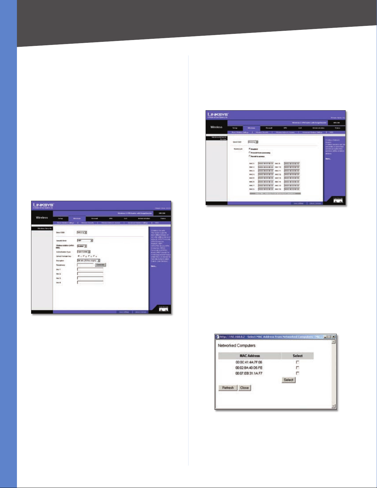
Wireless > Wireless Network Access
This screen allows you to control access to your wireless
network for each SSID.
Wireless > Wireless Network Access
Wireless Network Access
Wireless Security - WEP
Instead of manually entering WEP keys, you can enter
a Passphrase to generate one or more WEP keys. The
Passphrase is case-sensitive and should have no more
than 32 alphanumeric characters. If you want to use
a Passphrase, enter it in the Passphrase field and click
Generate.
If you want to enter the WEP key(s) manually, then enter
it in the Key 1-4 field(s). (Do not leave a field blank, and do
not enter all zeroes; they are not valid key values.) If you are
using 64-bit WEP encryption, the key must be exactly 10
hexadecimal characters in length. If you are using 128-bit
WEP encryption, the key must be exactly 26 hexadecimal
characters in length. Valid hexadecimal characters are “0”
to “9” and “A” to “F”.
When you have finished making changes to the screen,
click Save Settings to save the changes, or click Cancel
Access List To allow the designated computers to
access your network, select Permit to access. To block
the designated computers from accessing your wireless
network, select Prevent from accessing. Click Disabled
to disable the access function.
MAC 1-16 Enter the MAC addresses of the designated
computers. For a more convenient way to add MAC
addresses, click Select MAC Address From Networked
Computers. The Networked Computers screen will appear.
Select the MAC addresses you want. Then click Select.
Click Refresh if you want to refresh the screen. Click Close
to return to the previous screen.
Networked Computers
When you have finished making changes to the screen,
click Save Settings to save the changes, or click Cancel
Changes to undo your changes. For help information,
click More.
Wireless-G VPN Router with RangeBooster
16
Chapter 5
Configuring the Wireless-G Router
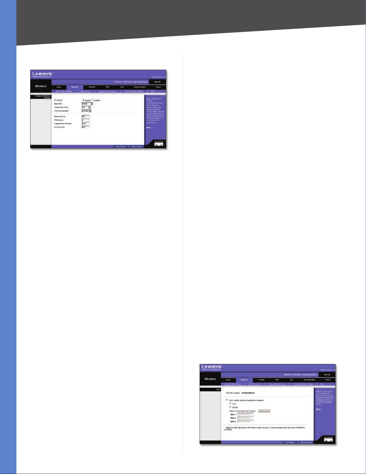
Wireless > Advanced Wireless Settings
Wireless > Advanced Wireless Settings
This tab is used to set up the Router’s advanced wireless
functions. These settings should only be adjusted by an
advanced user as incorrect settings can reduce wireless
performance.
Advanced Wireless Settings
AP Isolation This isolates all wireless clients and wireless
devices on your network from each other. Wireless devices
will be able to communicate with the Router but not with
each other. To use this function, click Enabled. AP Isolation
is disabled by default.
Basic Rate The Basic Rate setting is not actually one rate
of transmission but a series of rates at which the Router
can transmit. The Router will advertise its Basic Rate to the
other wireless devices in your network, so they know which
rates will be used. The Router will also advertise that it will
automatically select the best rate for transmission. The
default setting is Default, when the Router can transmit
at all standard wireless rates (1-2Mbps, 5.5Mbps, 11Mbps,
18Mbps, and 24Mbps). Other options are 1-2Mbps, for
use with older wireless technology, and All, when the
Router can transmit at all wireless rates. The Basic Rate
is not the actual rate of data transmission. If you want to
specify the Router’s rate of data transmission, configure
the Transmission Rate setting.
Transmission Power The amount of transmission power
should be set so that the Router uses only as much
power as needed to reach the farthest device in your
wireless network. This can help prevented unwanted
eavesdropping on your wireless network. You can select
from a range of power levels, from Full, Half, Quarter,
Eighth, or Min. The default setting is Full.
to catch all Wireless-G transmissions but will severely
decrease performance.
Beacon Interval The default value is 100. Enter a value
between 1 and 65,535 milliseconds. The Beacon Interval
value indicates the frequency interval of the beacon. A
beacon is a packet broadcast by the Router to synchronize
the wireless network.
DTIM Interval The default value is 3. This value, between
1 and 255, indicates the interval of the Delivery Traffic
Indication Message (DTIM). A DTIM field is a countdown
field informing clients of the next window for listening to
broadcast and multicast messages. When the Router has
buffered broadcast or multicast messages for associated
clients, it sends the next DTIM with a DTIM Interval value.
Its clients hear the beacons and awaken to receive the
broadcast and multicast messages.
Fragmentation Threshold In most cases, this value
should remain at its default value of 2346. It specifies the
maximum size for a packet before data is fragmented into
multiple packets. If you experience a high packet error rate,
you may slightly increase the Fragmentation Threshold.
Setting the Fragmentation Threshold too low may result
in poor network performance. Only minor reduction of
the default value is recommended.
RTS Threshold The RTS Threshold value should remain at
its default value, 2347. Should you encounter inconsistent
data flow, only minor reduction of the default value, 2347,
is recommended. If a network packet is smaller than the
preset RTS threshold size, the RTS/CTS mechanism will
not be enabled. The Router sends Request to Send (RTS)
frames to a particular receiving station and negotiates
the sending of a data frame. After receiving an RTS, the
wireless station responds with a Clear to Send (CTS) frame
to acknowledge the right to begin transmission.
When you have finished making changes to the screen,
click Save Settings to save the changes, or click Cancel
Changes to undo your changes. For help information,
click More.
Wireless > WDS
CTS Protection Mode CTS (Clear-To-Send) Protection
Mode’s default setting is Auto. The Router will automatically
use CTS Protection Mode when your Wireless-G products
are experiencing severe problems and are not able to
transmit to the Router in an environment with heavy
802.11b traffic. This function boosts the Router’s ability
Wireless-G VPN Router with RangeBooster
Wireless > WDS
17
Loading...