


 Loading...
¸
Release 1.0
Linksys SGE2000/SGE2000P Gigabit Ethernet Switch
Administration Guide
LINKSYS SGE2000/SGE2000P GIGABIT ETHERNET SWITCH
© 2007 Cisco Systems, Inc.
Specifications are subject to change without notice.
Linksys, the Cisco Systems logo, the Linksys Logo, and the Linksys One logo are registered trademarks of Cisco Systems, Inc. All other trademarks mentioned in this document are the property of their respective owners.

Linksys One Ready Communications Solution
Contents
Chapter 1: Introduction - - - - - - - - |
- |
- |
- |
- |
- |
- |
- |
- |
- |
- |
- |
- |
- |
- |
- |
- |
-1 |
|||
What’s in this User Guide? |
|
|
|
|
|
|
|
|
|
|
|
|
|
|
|
|
|
|
|
1 |
Chapter 2: Getting to Know the Switch |
|
- |
- |
- |
- |
- |
- |
- |
- |
- |
- |
- |
- |
- |
- |
- |
- |
-3 |
||
Overview |
|
|
|
|
|
|
|
|
|
|
|
|
|
|
|
|
|
|
|
3 |
The Front Panel |
|
|
|
|
|
|
|
|
|
|
|
|
|
|
|
|
|
|
|
3 |
Front Panel LEDs |
|
|
|
|
|
|
|
|
|
|
|
|
|
|
|
|
|
|
|
3 |
LAN Port LEDs |
|
|
|
|
|
|
|
|
|
|
|
|
|
|
|
|
|
|
|
4 |
Uplink Port LEDs |
|
|
|
|
|
|
|
|
|
|
|
|
|
|
|
|
|
|
|
4 |
Stack ID LEDs |
|
|
|
|
|
|
|
|
|
|
|
|
|
|
|
|
|
|
|
5 |
Reset Switch |
|
|
|
|
|
|
|
|
|
|
|
|
|
|
|
|
|
|
|
5 |
LAN Ports |
|
|
|
|
|
|
|
|
|
|
|
|
|
|
|
|
|
|
|
5 |
Uplink Ports |
|
|
|
|
|
|
|
|
|
|
|
|
|
|
|
|
|
|
|
6 |
The Back Panel |
|
|
|
|
|
|
|
|
|
|
|
|
|
|
|
|
|
|
|
6 |
Power Port |
|
|
|
|
|
|
|
|
|
|
|
|
|
|
|
|
|
|
|
7 |
Console Port |
|
|
|
|
|
|
|
|
|
|
|
|
|
|
|
|
|
|
|
7 |
RPS Port |
|
|
|
|
|
|
|
|
|
|
|
|
|
|
|
|
|
|
|
7 |
Chapter 3: Connecting the Switch |
- |
- |
- |
- |
- |
- |
- |
- |
- |
- |
- |
- |
- |
- |
- |
- |
- |
- |
- |
-8 |
Overview |
|
|
|
|
|
|
|
|
|
|
|
|
|
|
|
|
|
|
|
8 |
Before You Install the Switch... |
|
|
|
|
|
|
|
|
|
|
|
|
|
|
|
|
|
|
|
8 |
Placement Options |
|
|
|
|
|
|
|
|
|
|
|
|
|
|
|
|
|
|
|
9 |
Desktop Placement |
|
|
|
|
|
|
|
|
|
|
|
|
|
|
|
|
|
|
|
9 |
Rack-Mount Placement |
|
|
|
|
|
|
|
|
|
|
|
|
|
|
|
|
|
|
|
9 |
Wall-Mount Placement |
|
|
|
|
|
|
|
|
|
|
|
|
|
|
|
|
|
|
|
10 |
Connecting the Cables |
|
|
|
|
|
|
|
|
|
|
|
|
|
|
|
|
|
|
|
10 |
Stacking Multiple Switches |
|
|
|
|
|
|
|
|
|
|
|
|
|
|
|
|
|
|
|
12 |
Connecting Cabling for Stacking |
|
|
|
|
|
|
|
|
|
|
|
|
|
|
|
|
|
|
13 |
|
Chapter 4: Console Configuration |
- |
- |
- |
- |
- |
- |
- |
- |
- |
- |
- |
- |
- |
- |
- |
- |
- |
- |
- 14 |
|
Overview |
|
|
|
|
|
|
|
|
|
|
|
|
|
|
|
|
|
|
|
14 |
Configuring the HyperTerminal Application |
|
|
|
|
|
|
|
|
|
|
|
|
|
|
|
|
14 |
|||
i

Linksys One Ready Communications Solution
Connecting to the Switch using Telnet or SSH |
16 |
Configuring the Switch through the Console or Telnet Interface |
16 |
Switch Main Menu |
17 |
Chapter 5: Web Utility Configuration |
- |
- |
- |
- |
- |
- |
- |
- |
- |
- |
- |
- |
- |
- |
- |
- |
- |
31 |
||
Overview |
|
|
|
|
|
|
|
|
|
|
|
|
|
|
|
|
|
|
|
31 |
Accessing the Web-based Utility |
|
|
|
|
|
|
|
|
|
|
|
|
|
|
|
|
|
|
|
31 |
Viewing Online Help |
|
|
|
|
|
|
|
|
|
|
|
|
|
|
|
|
|
|
|
31 |
Appendix A: Linksys Contact Information |
- |
- |
- |
- |
- |
- |
- |
- |
- |
- |
- |
- |
- |
- |
- |
32 |
||||
Appendix B: Customer Site Survey |
|
- |
- |
- |
- |
- |
- |
- |
- |
- |
- |
- |
- |
- |
- |
- |
- |
- |
- |
34 |
Appendix C: Limited Warranty - |
- |
- |
- |
- |
- - - - - - - - - - - - - - - |
37 |
||||||||||||||
Appendix D: Federal Communication Commission Interference Statement |
39 |
|||||||||||||||||||
Industry Canada Statement |
|
|
|
|
|
|
|
|
|
|
|
|
|
|
|
|
|
|
|
39 |
EC Declaration of Conformity (Europe) |
|
|
|
|
|
|
|
|
|
|
|
|
|
|
|
|
39 |
|||
Appendix E: Specifications - - - |
- |
- |
- |
- |
- |
- |
- |
- |
- |
- |
- |
- |
- |
- |
- |
- |
- |
- |
- |
40 |
ii
Chapter
Linksys One Ready Communications Solution
1 Introduction
Welcome
Thank you for choosing a Linksys Ethernet switch. This Ethernet switch allows you to quickly and easily expand your Linksys One system. It delivers non-blocking, wire speed switching for your network clients, plus multiple options for connecting to your network backbone.
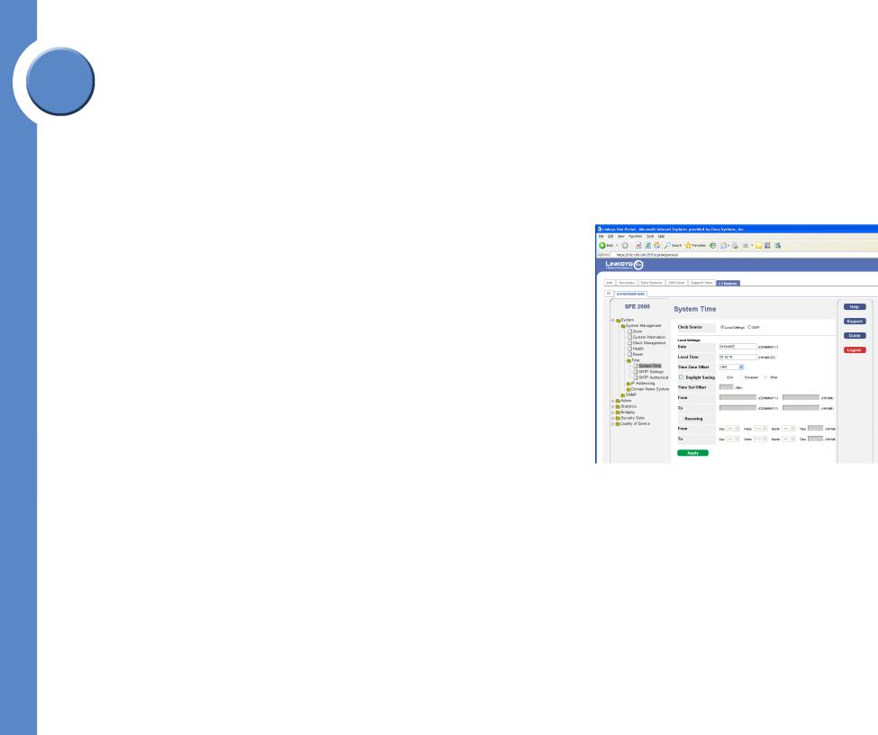
Twenty four ports wire up your workstations or connect to other Linksys switches or devices. Linksys One Portal LED indicators provide power, link, and activity status.
The Ethernet switch features monitoring and configuration via the Linksys One Portal, your web browser, or the console interface. If your Ethernet switch is part of a Linksys One system, the easiest way to manage it is with the Linksys One Portal — available only on the Linksys One Services Router. Refer to the Linksys One Customer Premises Equipment Administration Guide for more details on the Linksys One Portal.
The Ethernet switch supports numerous security features including the Remote Authorization and Authentication (RADIUS) and Terminal Access Controller Access Control System (TACACS+) protocols. With Simple Network Time Protocol (SNTP), the Ethernet switch can synchronize its clock with a time server available on one of its attached networks.
The system is fully manageable using a combination of a database of MIB (Management Information Base) variables, whose combined values represent all facets of the system state, and the Simple Network Management Protocol (SNMP) protocol.
The “P” model of the Ethernet switch supports Power over Ethernet (PoE) which eliminates the need to run 110/220 VAC power to wireless network, IP telephony, or other PoE powered devices on the Linksys network. Use of a PoE system allows greater flexibility in locations of network devices, and significantly decreasing installation costs. The entire PoE system can be centrally powered by uninterruptible power supplies if necessary.
What’s in this User Guide?
This user guide covers the steps for setting up and using the Ethernet switch. Use the instructions in this guide to help you connect the switch, set it up, and configure it to your Linksys network. These instructions should be all you need to get the most out of your Ethernet switch.
Chapter 1: Introduction |
1 |
What’s in this User Guide? |
|

This user guide contains the following chapters:
Chapter 1, "Introduction"
This chapter describes the Ethernet switch applications and provides an overview of the content of this administration guide.
Chapter 2, "Getting to Know the Switch"
This chapter describes the physical features of the Ethernet switch. Chapter 3, "Connecting the Switch"
This chapter explains how to install and connect the Ethernet switch. Chapter 4, "Console Configuration"
This chapter describes how to use the console interface when you configure the Ethernet switch.
Chapter 5, "Web Utility Configuration"
This chapter shows you how to configure the Ethernet switch using the Web-based Utility.
Linksys One Ready Communications Solution
1
Chapter
2 |
Chapter 1: Introduction |
|
What’s in this User Guide? |
Chapter
Linksys One Ready Communications Solution
2 Getting to Know the Switch
Overview
The SGE2000 and SGE2000P models are 24-port, layer-2 Ethernet switches that expand the capability of the Linksys system. These two versions are functionally identical except the SGE2000P model offers Power-over-Ethernet (PoE) which can be used to supply power to various Linksys products over Ethernet cable.
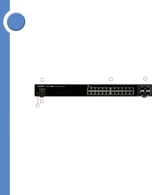
The Front Panel
The Switch's LEDs and Ethernet ports are located on the front panel.
1 |
2 |
3 |
|||||
|
|
|
|
|
|
|
|
|
|
|
|
|
|
|
|
|
|
|
|
|
|
|
|
|
|
|
|
|
|
|
|
|
|
|
|
|
|
|
|
|
|
|
|
|
|
|
|
|
|
|
|
|
|
|
|
|
|
|
|
|
|
|
|
4 
5 
Front Panel LEDs
The Switch uses Light Emitting Diodes (LEDs) to indicate the status of numerous functions. These functions are listed below.
|
System Status LEDs. Four LEDs indicate the status |
|
1 |
of the Ethernet switch power, fan, RPS connectivity, |
|
and stack master. For more details, refer to |
||
|
||
|
”System Status LEDs,” on page 4. |
|
|
|
|
|
LAN Ports. Twenty four 10/100/1000 BaseT LAN |
|
2 |
ports provide connectivity to other Linksys devices. |
|
For more details, refer to ”LAN Ports,” on |
||
|
||
|
page 5. |
|
|
|
|
|
Gigabit Interface Converter (mini-GBIC) Uplink |
|
|
Ports. Four mini-GBIC ports provide uplink ports |
|
3 |
which support network speeds of 10Mbps, |
|
|
100Mbps, and 1000Mbps. For more details, refer |
|
|
to ”Uplink Ports,” on page 6. |
|
|
|
|
|
Stack ID. If stacking is active, indicates the ID |
|
4 |
number of the stack. For more details, refer to |
|
|
”Stack ID LEDs,” on page 4. |
|
|
|
|
|
RESET Switch. Resets the SGE2000/SGE2000P |
|
5 |
Ethernet switch. For more details, refer to ”Reset |
|
|
Switch,” on page 5. |
|
|
|
Chapter 2: Getting to Know the Switch |
3 |
Overview |
|

System Status LEDs
PWR |
A green PWR LED lights to indicate that the Ethernet switch is powered |
|
by internal power supplies. If the Ethernet switch is powered by a |
|
remote power supply (RPS), this LED blinks red. |
FAN |
A green FAN LED lights to indicate that the cooling fan is operating |
|
properly. A blinking red FAN LED indicates that the cooling fan has |
|
failed. |
RPS |
A green RPS LED lights to indicate that RPS is connected and operating |
|
properly. A blinking red RPS LED indicates an RPS fault. |
MST |
A green MST LED indicates that this Ethernet switch is a stack master. |
LAN Port LEDs |
|
Act/Link |
The green Act/Link LEDs light to indicate a functional network link |
|
through the corresponding port with an attached device. The Act |
|
(Activity) LEDs flash to indicate that the Ethernet switch is actively |
|
sending or receiving data over that port. |
Uplink Port LEDs |
|
Act/Link |
The green Act/Link LEDs light to indicate a functional network link |
|
through the corresponding port with an attached device. The Act |
|
(Activity) LEDs flash to indicate that the Ethernet switch is actively |
|
sending or receiving data over that port. |
Gigabit |
The Gigabit LED lights indicate a Gigabit connection on the |
|
corresponding port. |
Stack ID LEDs |
|
Stack ID |
A green Stack ID LED indicates that this Switch is stacked and the |
|
corresponding number indicates its stack ID. Range is 1 to 8. |
Linksys One Ready Communications Solution
2
Chapter
4 |
Chapter 2: Getting to Know the Switch |
|
The Front Panel |

Chapter
Linksys One Ready Communications Solution
2 |
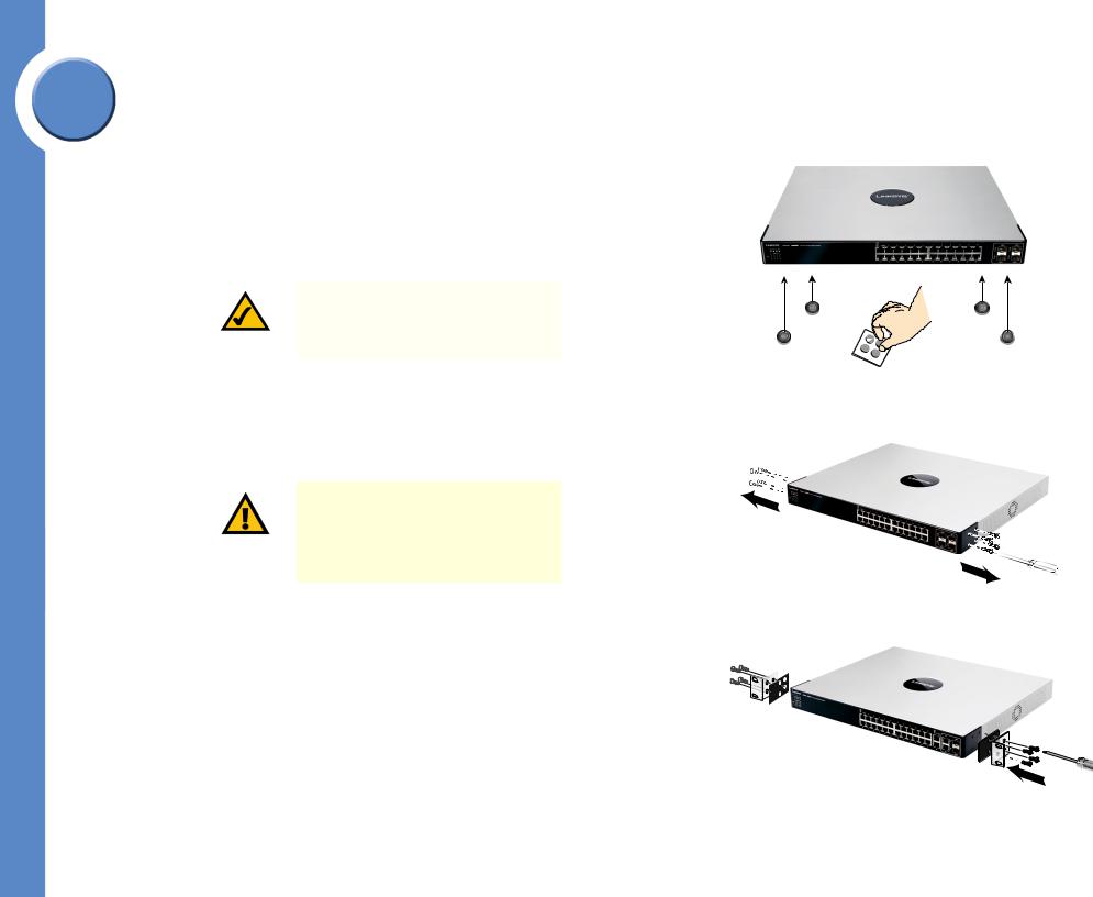
Reset Switch |
||
|
|||
|
The Ethernet switch can be reset by inserting a pin or paper clip into the RESET opening. If |
||
|
the reset switch is held for 10 seconds or longer, the Ethernet switch will be reset to its default |
||
|
settings. |
||
|
|
|
|
|
|
CAUTION: All user-defined settings are |
|
|
|
lost when you hold the Reset button for |
|
|
|
10 seconds or longer; the Ethernet |
|
|
|
switch reverts to its default settings. |
|
|
|
|
|
|
When a unit is reset to its default setting, the unit restarts in stackable mode using default |
||
|
stacking ports with autonumbering enabled. Pressing the reset button on the master unit of a |
||
|
stack resets all units in the stack. |
||
|
LAN Ports |
||
|
The Ethernet switch is equipped with 24 Ethernet ports. |
||
1-24 |
The Switch is equipped with 24 auto-sensing, Ethernet (IEEE 802.3) |
|
network ports, which use RJ-45 connectors. The Gigabit Ethernet ports |
|
support network speeds of 10Mbps, 100Mbps, and 1000Mbps. They |
|
can operate in half and full-duplex modes. Auto-sensing technology |
|
enables each port to automatically detect the speed of the device |
|
connected to it, and adjust its speed and duplex accordingly. |
In stacking mode, two ports are used for stacking. By default, the stacking ports are 12 and 24.
Ports 11, 12, 23, and 24 are shared with GBIC1, GBIC3, GBIC2, GBIC4 respectively. If shared port pairs are both connected, then the mini-GBIC port takes priority.
Chapter 2: Getting to Know the Switch |
5 |
The Front Panel |
|
Uplink Ports
The Switch is equipped with 4 mini-GBIC uplink ports.
GBIC1-4 The Switch provides four mini-GBIC ports. The mini-GBIC port is a connection point for a mini-GBIC expansion module, so the Switch can be uplinked via fiber or copper to another switch. Each mini-GBIC port provides a link to a high-speed network segment or individual workstation at speeds of up to 1000Mbps.
Use the Linksys MGBT1, MGBSX1, or MGBLH1 mini-GBIC modules with the Switch. The MGBSX1 and the MGBLH1 require fiber cabling with LC connectors, while the MGBT1 requires a Category 5e Ethernet cable with an RJ-45 connector.
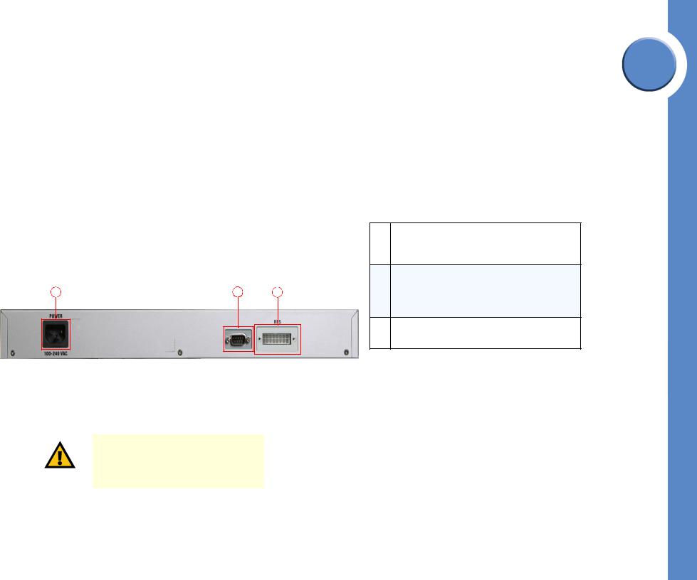
The Back Panel
The power port is located on the back panel of the Ethernet switch.
1 |
2 |
3 |
DC INPUT FOR REMOTE
POWER SUPPLY SPECIFIED
IN MANUAL +12V, 7.5A
Power Port
The 100-240 VAC power cord is connected to the Power port.
CAUTION: Only use the power cord that is supplied with the Ethernet switch. The unit may be damaged if the incorrect power cord is used.
Linksys One Ready Communications Solution
2
Chapter
Power Port. The Power port is where you will
1connect the power cord. For more details, refer to
”Power Port,” on page 6.
Console Port. The Console port is where you can connect a serial cable to a PC’s serial port for
2configuration. For more details, refer to ”Console Port,” on page 7.
RPS Port. Redundant Power Supply (RPS) port. For
3more details, refer to ”RPS Port,” on page 7.
6 |
Chapter 2: Getting to Know the Switch |
|
The Back Panel |
Chapter
Linksys One Ready Communications Solution
2 |
Console Port |
||
|
|||
|
The Console port is where you connect a serial cable to a PC’s serial port for configuration |
||
|
using your PC’s HyperTerminal program. Refer to ”Configuring the HyperTerminal |
||
|
Application,” on page 14 for more information. |
||
|
|
|
|
|
|
NOTE: Many modern laptop computers |
|
|
|
are not supplied with serial ports. You |
|
|
|
may use a USB-to-Serial adapter on |
|
|
|
your laptop to connect to the console |
|
|
|
serial port. |
|
|
|
|
|
|
RPS Port |
||
|
An optional Redundant Power Supply (RPS) is connected to the RPS port. An RPS enhances |
||
|
the reliability of the Ethernet switch and it can keep the unit running if a power failure |
||
|
occurs. Only use a Linksys RPS1000 Redundant Power Supply unit and a proper RPS cable |
||
|
(RPSCBL1) with the Ethernet switch. |
||
|
|
|
|
|
|
WARNING: Do not remove the cover |
|
|
|
from the RPS port unless an RPS unit is |
|
|
|
connected to the Ethernet switch. Keep |
|
|
|
the RPS port covered when not in use. |
|
|
|
|
|
Chapter 2: Getting to Know the Switch |
7 |
The Back Panel |
|
Connecting the Switch
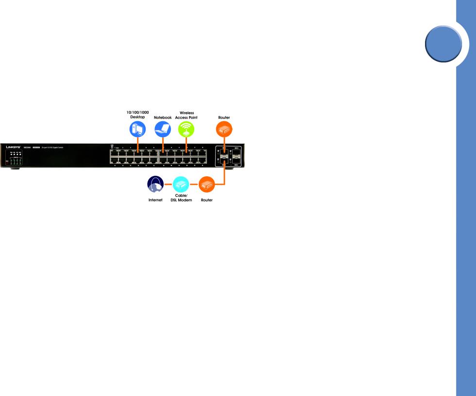
Overview
This chapter will explain how to connect network devices to the Ethernet switch. For an example of a possible network configuration, see the application diagrams shown below.
Before You Install the Switch...
When you choose a location for the Ethernet switch, observe the following guidelines:
•Make sure that the Ethernet switch will be accessible and that the cables can be easily connected.
•Keep cabling away from sources of electrical noise, power lines, and fluorescent lighting fixtures.
•Position the Ethernet switch away from water and moisture sources.
•To ensure adequate air flow, be sure to provide a minimum clearance of two inches (50 mm) around the air intake and exhaust ports on the sides of the Ethernet switch.
•Do not stack free-standing Ethernet switches more than four units high. The stacking configuration, described in ”Stacking Multiple Switches,” on page 12, allows up to eight
Linksys One Ready Communications Solution
3
Chapter
8 |
Chapter 3: Connecting the Switch |
|
Overview |
Chapter
|
Linksys One Ready Communications Solution |
3 |
units to be logically stacked together. It is recommended that multiple Ethernet switches |
be mounted in a rack when installed in this manner. Ethernet switches can be physically |
|
|
placed at different locations; they do not have to be stacked at the same location. |
|
Placement Options |
|
Before connecting cables to the Ethernet switch, first you will physically install the Ethernet |
|
switch. Either set the Ethernet switch on its four rubber feet for desktop placement, mount it in |
|
a standard-sized, 19-inch wide for rack-mount placement, or mount it on a wall with the |
|
wall-mount brackets provided. |
NOTE: The four supplied mounting brackets can be used for either wall mount or rack mount installations.
Desktop Placement
1.Attach the rubber feet to the recessed areas on the bottom of the Ethernet switch.
2.Place the Ethernet switch on a desktop near an AC power source.
CAUTION: Keep enough ventilation space for the Ethernet switch so it does not exceed the environmental restrictions mentioned in the specifications.
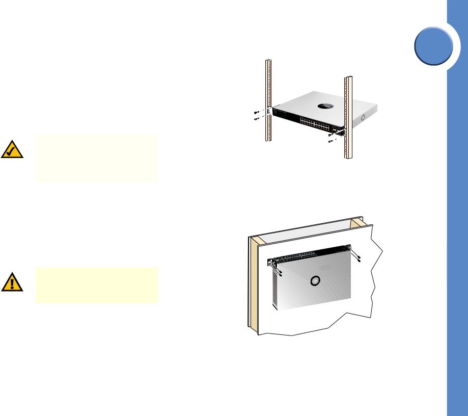
Rack-Mount Placement
To mount the Ethernet switch in any standard-sized, 19-inch wide, (each Ethernet switch requires 1RU of space in the rack), follow these instructions:
1.Remove the four front screws on one side of the Ethernet switch. Retain the screws for reinstallation.
2.Place one of the supplied spacers on the side of the Ethernet switch so the four holes align to the screw holes.
Chapter 3: Connecting the Switch |
9 |
Placement Options |
|
3.Place a rack mount bracket next to the spacer and reinstall the four screws (removed in step 1).
4.Repeat steps 2 through 3 for the other side of the Ethernet switch.
5.Attach the Ethernet switch to the rack using the supplied screws.
Wall-Mount Placement
1.On one of the side corners, remove the four front screws on of the Ethernet switch. Retain the screws for re-installation.
NOTE: The Ethernet switch, shown below, is mounted with the ports located on top. When the switch is mounted to a wall, the ports can be oriented in any direction.
2.Place one of the supplied spacers on the side of the Ethernet switch so the four holes align to the screw holes.
3.Place a rack mount bracket next to the spacer and reinstall the four screws (removed in step 1). The wall mount brackets should point towards the bottom of the Ethernet switch.
4.Repeat steps 1 through 3 for the other corners of the Ethernet switch.
5.Attach the Ethernet switch to a wall with appropriate screws (not supplied).
CAUTION: Ensure that the Ethernet switch is securely attached to the wall.
Linksys One Ready Communications Solution
3
Chapter
10 |
Chapter 3: Connecting the Switch |
|
Placement Options |
Chapter
Linksys One Ready Communications Solution
3 |
Connecting the Cables |
|||
|
To connect network devices to the Ethernet switch, follow these instructions: |
|||
|
1. |
For 10/100Mbps devices, connect a Category 5 Ethernet network cable to one of the |
||
|
|
numbered ports on the Ethernet switch. For a 1000Mbps device, connect a Category 5e |
||
|
|
Ethernet network cable to one of the uplink ports on the Ethernet switch. |
||
|
2. |
Connect the other end to a PC or other network device. |
||
|
3. |
Repeat steps 2 and 3 to connect additional devices. |
||
|
4. |
If you are using the mini-GBIC port, then insert the mini-GBIC module to the mini-GBIC |
||
|
|
port. For detailed instructions, refer to the documentation supplied with the mini-GBIC |
||
|
|
module. |
||
|
|
|
|
|
|
|
|
CAUTION: Observe the orientation of |
|
|
|
|
the mini-GBIC module before inserting it |
|
|
|
|
into a mini-GBIC port. The bottom mini- |
|
|
|
|
GBIC ports are upside down in relation |
|
|
|
|
to the top mini-GBIC ports. |
|
|
|
|
|
|
|
5. |
If you use the console interface to configure the Ethernet switch, then connect the |
||
|
|
supplied serial cable to the console port (located on the back of the Ethernet switch), and |
||
|
|
tighten the captive retaining screws. Connect the other end to your PC’s serial port. (The |
||
|
|
PC must be running VT100 terminal emulation software, such as HyperTerminal.) |
||
|
6. |
Connect the supplied power cord to the power port, and plug the other end into an |
||
|
|
electrical outlet. |
||
|
|
|
|
|
|
|
|
CAUTION: Make sure you use the |
|
|
|
|
power cord that is supplied with the |
|
|
|
|
Ethernet switch. Use of a different |
|
|
|
|
power cord could damage the Ethernet |
|
|
|
|
switch. |
|
|
|
|
|
|
|
7. |
Power on the network devices connected to the Ethernet switch. Each active port’s |
||
|
|
corresponding Act/Link LED will light up on the Ethernet switch. If a port has an active |
||
|
|
Gigabit connection, then its corresponding Gigabit LED will also light up. |
||
NOTE: If connecting an Ethernet switch to an SVR3000 router, connect it to a Cascade port on the SVR3000.
Chapter 3: Connecting the Switch |
11 |
Connecting the Cables |
|
Loading...