


 Loading...
User Guide
AC2600 Dual-Band
Wireless Access Point
LAPAC2600
1
Contents |
|
Chapter 1 – Quick Start Guide........................................................................... |
4 |
Package Contents................................................................................................................................... |
4 |
Physical Details........................................................................................................................................ |
4 |
Mounting Guide ........................................................................................................................................ |
5 |
Chapter 2 –Quick Start......................................................................................... |
7 |
Overview..................................................................................................................................................... |
7 |
Setup Using a Web Browser................................................................................................................ |
7 |
Setup Wizard............................................................................................................................................. |
9 |
Chapter 3 – Configuration ................................................................................ |
13 |
Administration....................................................................................................................................... |
13 |
LAN ............................................................................................................................................................ |
24 |
Wireless.................................................................................................................................................... |
30 |
Captive Portal........................................................................................................................................ |
64 |
ACL ............................................................................................................................................................ |
76 |
Cluster...................................................................................................................................................... |
83 |
Chapter 4 - System Status .............................................................................. |
92 |
Status ....................................................................................................................................................... |
92 |
Chapter 5 – Maintenance................................................................................ |
103 |
Maintenance........................................................................................................................................ |
103 |
Diagnostics.......................................................................................................................................... |
110 |
Appendix A - Troubleshooting ....................................................................... |
113 |
Overview............................................................................................................................................... |
113 |
General Problems .............................................................................................................................. |
113 |
Appendix B - About Wireless LANs.............................................................. |
115 |
Overview............................................................................................................................................... |
115 |
Wireless LAN Terminology ............................................................................................................. |
115 |
|
2 |
Appendix C - PC and Server Configuration .............................................. |
119 |
Overview............................................................................................................................................... |
119 |
Using WEP............................................................................................................................................ |
119 |
Using WPA2-PSK .............................................................................................................................. |
120 |
Using WPA2-Enterprise.................................................................................................................. |
120 |
802.1x Server Setup (Windows 2000 Server)....................................................................... |
122 |
802.1x Client Setup on Windows XP......................................................................................... |
132 |
Using 802.1x Mode (without WPA)............................................................................................. |
139 |
3
Chapter 1 -- Quick Start Guide
Package Contents
•Linksys Wireless Access Point
•Quick Start Guide
•Ethernet Cable
•AC Power Adapter
•CD with Documentation
•Mounting Bracket
•Mounting Kit
•Ceiling Mount Back Plate
•Drilling Layout Template
Physical Details
LED behavior
LED Color |
Activity |
Status |
|
Green |
Blinking |
System is booting. |
|
|
|
||
|
Solid |
System is normal; no wireless devices connected. |
|
|
|
|
|
Blue |
Blinking |
Software upgrade in process. |
|
|
|
||
Solid |
System is normal; at least one wireless device connected. |
||
|
|||
Red |
Solid |
Booting process or update failed; hard reset or service |
|
required. |
|||
|
|
Ports and Button
Power Port—Connect the AC power adapter to this port.
Note—Use only the adapter that came with your access point.
Ethernet Port 1—Use an RJ45 (CAT5e or better) cable to connect the LAPAC2600 to network devices such as routers, switches and computers. This port supports PoE+ (IEEE 802.3at). You may use the port to power LAPAC2600 by using PoE+ switch or injector.
4
Note—System power consumption is over 15W. Make sure your PoE switch or injector is 803.2at-capable (PoE+) and provides sufficient power. If your PoE switch or injector is not 802.3at-capable, use the provided power adapter. If the PoE and AC power adapters are connected to the LAPAC2600 at the same time, the device will get power from PoE.
Ethernet Port 2—This is a non-PoE Ethernet port. It can be used instead of Ethernet port 1 but requires an AC power adapter.
Note—LAG (Link Aggregation) is enabled by default on Ethernet Port 1 and 2. Refer to your switch configuration guide, and enable one LAG with LACP (802.3ad Link Aggregation Control Protocol) on the switch if you intend to plug two Ethernet cables into switch. In this configuration, it is highly recommended that AC power and PoE be used in tandem in case of support power failure and/or link failure. If your switch does not support LAG, you can only use one Ethernet port at a time on your LAPAC2600.
Reset Button—Press and hold this button for less than 15 seconds to power cycle device. Press and hold for longer than 15 seconds to reset the device to factory default settings.
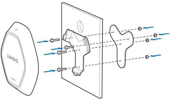
Mounting Guide
To avoid overheating, do not install your access point if ambient temperatures exceed 104°F (40°C). Install on a flat, stable surface, near the center of your wireless coverage area making sure not to block vents on the sides of the device enclosure.
Wall Installation
1.Position drilling layout template at the desired location.
2.Drill four screw holes on the mounting surface. If your Ethernet cable is routed behind the wall, mark Ethernet cable hole as well.
3.Secure the mounting bracket on the wall with anchors and screws.
4.If your Ethernet cable is routed behind the wall, cut or drill the Ethernet cable hole you marked in Step 2. Feed the Ethernet cable through the hole.
5.Connect the Ethernet cable and/or AC power adapter to your device.
6.Slide the device into the bracket. Turn clockwise until it locks into place.
5
Ceiling Installation
1.Select ceiling tile for mounting and remove tile.
2.Position drilling layout template at the desired location.
3.Drill four screw holes and Ethernet cable hole on the surface of ceiling tile.
4.Place back plate on the opposite side of ceiling tile. Secure mounting bracket to the ceiling tile with flathead screw and nut. Route the Ethernet cable through the Ethernet cable hole.
5.Replace tile in ceiling.
6.Connect the Ethernet cable and/or AC power adapter to your device
7.Slide the device into the bracket. Turn access point clockwise until it locks.
IMPORTANT—Improper or insecure mounting could result in damage to the device or personal injury. Linksys is not responsible for damages caused by improper mounting.
6
Chapter 2 --Quick Start
Overview
This chapter describes the setup procedure to connect the wireless access point to your LAN, and configure it as an access point for your wireless stations.
Wireless stations may also require configuration. For details, see Appendix C - Wireless Station Configuration (p. 119).
The wireless access point can be configured using a web browser.
Note—Licenses and notices for third party software used in this product may be viewed on http://support.linksys.com/en-us/license. Please contact http://support.linksys.com/enus/gplcodecenter for questions about GPL source code requests.
Setup Using a Web Browser
Your browser must support JavaScript. The configuration program has been tested on the following browsers:
•Firefox 3.5 or later, Chrome 8 or later, Safari 5 or later
•Internet Explorer 8 or later
Setup Procedure
Make sure device is powered on before you continue setup. If LED light is off, check that AC power adapter, or PoE cable, is properly connected on both ends.
Access device’s browser-based setup:
1.Use the included cable to connect the access point to your network via a network switch or router.
2.Open a web browser on a computer connected to your network. Enter the IP address of your access point. By factory default, the IP address will be assigned by a DHCP server (usually the network router). If there is no DHCP server on your network, the default IP address is 192.168.1.252/255.255.255.0.
Note—Use a computer hardwired to the same network as your access point for browser-based setup access. Access to browser-based setup via Wi-Fi is disabled by default.
3. Type in default username: “admin”, and password: “admin”.
7
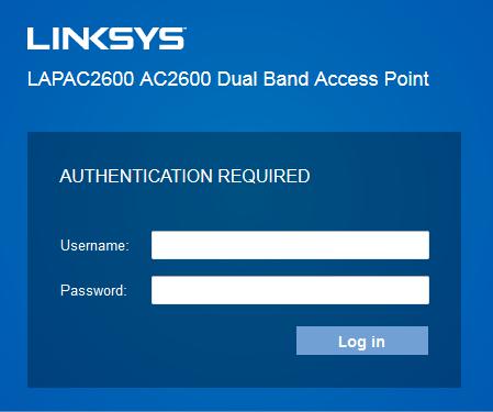
4. Click Log in to launch the browser-based setup and follow the on-screen instructions.
If you can't connect:
It is likely that your PC’s IP address is incompatible with the wireless access point’s IP address. This can happen if your LAN does not have a DHCP Server. If there is no DHCP server in your network, the access point will fall back to its default IP address: 192.168.1.252, with a network mask of 255.255.255.0.
Or, if your PC’s IP address is not compatible with this, you must change your PC’s IP address to an unused value in the range 192.168.1.1 ~ 192.168.1.254, with a network mask of 255.255.255.0. See Appendix A - Windows TCP/IP (p. 113) for details for this procedure.
8
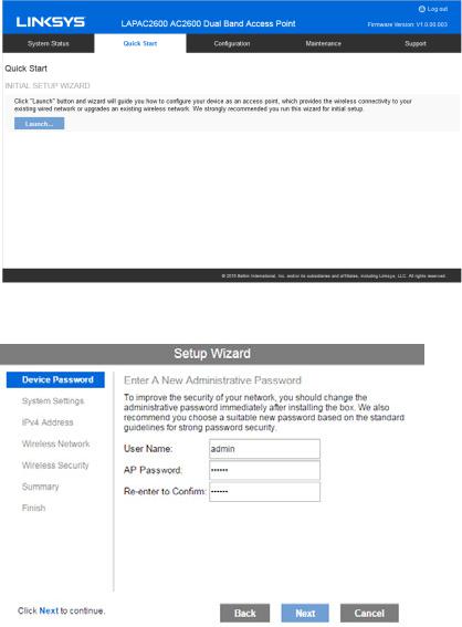
Setup Wizard
If you are setting up the access point as a standalone device, run the Setup Wizard. If the access point will be part of a cluster – master or slave - go to Configuration > Cluster > Settings & Status page instead.
1. Click the Quick Start tab on the main menu.
2.On the first screen, click Launch...
3.Set the password on the Device Password screen, if desired.
4. Configure the time zone, date and time for the device on System Settings screen.
9

5.On the IPv4 Address screen configure the IP address of the device (Static or Automatic) then click Next.
10
6.Set the SSID information on the Wireless Network screen. Click Next. If you want to configure more than four SSIDs, go to Configuration > Wireless > Basic Settings. The access point supports up to eight SSIDs per radio.
7.On the Wireless Security Screen, configure the wireless security settings for the device. Click Next. If you are looking for security options that are not available in the wizard, go to Configuration > Wireless Security page. The access point supports more sophisticated security options there.
11
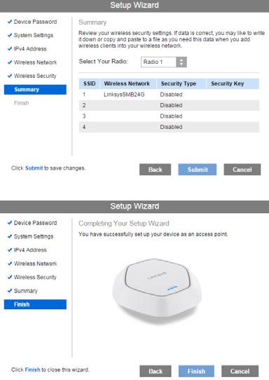
8.On the Summary screen, check the data to make sure they are correct and then click Submit to save the changes.
9. Click Finish to leave the wizard.
12
Chapter 3 -- Configuration
Administration
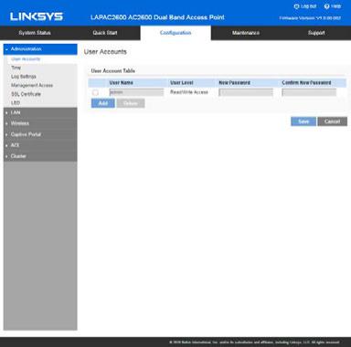
User Accounts
Go to Configuration > Administration and select User Accounts to manage user accounts. The access point supports up to five users: one administrator and four normal users.
13
User Account Table
User Name |
Enter the User Name to connect to the access point’s admin |
|
interface. User Name is effective once you save settings. |
|
User Name can include up to 63 characters. Special |
|
characters are allowed. |
|
|
User Level |
Only administrator account has Read/Write permission to |
|
the access point’s admin interface. All other accounts have |
|
Read Only permission. |
|
|
New Password |
Enter the Password to connect to the access point’s admin |
|
interface. |
|
Password must be between 4 and 63 characters. Special |
|
characters are allowed. |
|
|
Confirm New |
Re-enter password. |
Password |
|
|
|
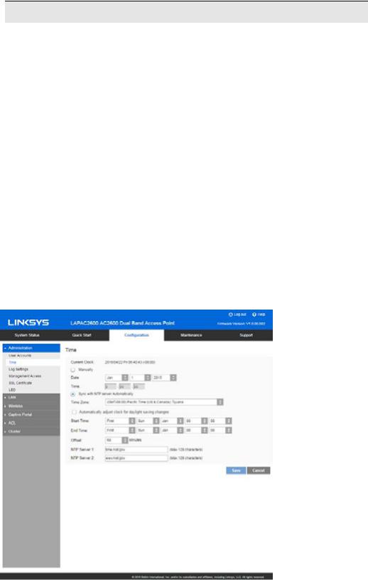
Time
Go to Configuration > Administration and select Time to configure system time of the device.
14

Time
Current Time |
Display current date and time of the system. |
|
|
Manually |
Set date and time manually. |
|
|
Automatically |
When enabled (default setting) the access point will get the |
|
current time from a public time server. |
|
|
Time Zone |
Choose the time zone for your location from the drop-down |
|
list. If your location observes daylight saving time, enable |
|
Automatically adjust clock for daylight saving changes. |
|
|
Start Time |
Specify the start time of daylight saving. |
|
|
End Time |
Specify the end time of daylight saving. |
|
|
Offset |
Select the adjusted time of daylight saving. |
|
|
NTP |
|
|
|
NTP Server 1 |
Enter the primary NTP server. It can be an IPv4 address or a |
|
domain name. |
|
Valid characters include alphanumeric characters, "_", "-" |
|
and ".".Maximum length is 64 characters. |
|
|
NTP Server 2 |
Enter the secondary NTP server. It can be an IPv4 address |
|
or a domain name. |
|
Valid characters include alphanumeric characters, "_", "-" |
|
and ".".Maximum length is 64 characters. |
|
|
15
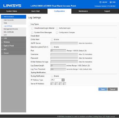
Log Settings
Go to Configuration > Administration and select Log Settings to configure logs. Logs record various types of activity on the access point. This data is useful for troubleshooting, but enabling all logs will generate a large amount of data and adversely affect performance.
16

Log Types
Log Types |
Select events to log. Checking all options increase the |
|
size of the log, so enable only events you believe are |
|
required. |
|
|
Email Alert |
|
|
|
Email Alert |
Enable email alert function. |
|
|
SMTP Server |
Enter the e-mail server that is used to send logs. It can |
|
be an IPv4 address or a domain name. |
|
Valid characters include alphanumeric characters, "_", "- |
|
" and ".". Maximum length is 64 characters. |
|
|
Data Encryption |
Enable if you want to use data encryption. |
|
|
Port |
Enter the port for the SMTP server. The port is a value |
|
from 1 to 65535 and default is 25. |
|
|
Username |
Enter the Username to login to your SMTP server. |
|
The Username can include up to 32 characters. Special |
|
characters are allowed. |
|
|
Password |
Enter the Password to login to your SMTP server. |
|
The Password can include up to 32 characters. Special |
|
characters are allowed. |
|
|
Email Address for |
Enter the email address the log messages are to be |
Logs |
sent to. |
|
Valid characters include alphanumeric characters, "_", "- |
|
", "." and "@". Maximum length is 64 characters. |
|
|
Log Queue Length |
Enter the length of the queue: up to 500 log messages. |
|
The default is 20 messages. When messages reach the |
|
set length the queue will be sent to the specified email |
|
address. |
|
|
Log Time |
Enter the time threshold (in seconds) used to check if |
Threshold |
the queue is full. It’s a value from 1 to 600 and default |
|
is 600 seconds. |
|
|
Syslog |
|
|
|
Syslog Notification |
Enable Syslog notification. |
|
|
IP Type |
Select the IP type of the syslog server: IPv4 or IPv6. |
|
|
Server IP Address |
Enter the IPv4 or IPv6 address of syslog server here. |
|
|
17
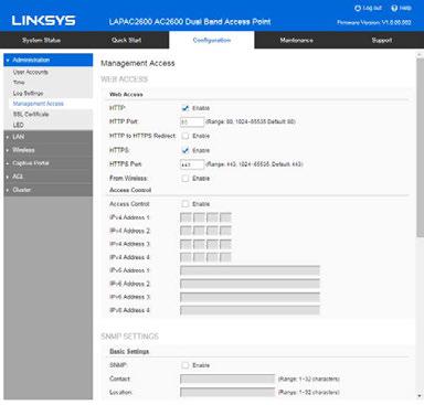
Management Access
Go to Configuration > Administration and select Management Access page to configure the management methods of the access point.
18

Web Access
HTTP |
HTTP (HyperText Transfer Protocol) is the standard for |
|
transferring files (text, graphic images and other |
|
multimedia files) on the World Wide Web. |
|
Enable to allow Web access by HTTP protocol. |
|
|
HTTP Port |
Specify the port for HTTP. It can be 80 (default) or from |
|
1024 to 65535. |
|
|
HTTP to HTTPS |
Enable to redirect Web access of HTTP to HTTPS |
Redirect |
automatically. |
|
This field is available only when HTTP access is |
|
disabled. |
|
|
HTTPS |
HTTPS (Hypertext Transfer Protocol Secure) can |
|
provide more secure communication with the SSL/TLS |
|
protocol, which support data encryption to HTTP |
|
clients and servers. |
|
Enable to allow Web access by HTTPS protocol. |
|
|
HTTPS Port |
Specify the port for HTTPS. It can be 443 (default) or |
|
from 1024 to 65535. |
|
|
From Wireless |
Enable wireless devices to connect to access point’s |
|
admin page. Disabled by default. |
|
|
Access Control |
By default, no IP addresses are prohibited from |
|
accessing the device’s admin page. You can enable |
|
access control and enter specified IP addresses for |
|
access. Four IPv4 and four IPv6 addresses can be |
|
specified. |
|
|
SNMP Settings |
|
|
|
SNMP |
Simple Network Management Protocol (SNMP) is a |
|
network monitoring and management protocol. |
|
Enable or disable SNMP function here. Disabled by |
|
default. |
|
|
Contact |
Enter contact information for the access point. |
|
The contact includes 1 to 32 characters. Special |
|
characters are allowed. |
|
|
19

Location |
Enter the area or location where the access point |
|
resides. |
|
The location includes 1 to 32 characters. Special |
|
characters are allowed. |
|
|
SNMP v1/v2 Settings
Get Community Enter the name of Get Community. Get Community is used to read data from the access point and not for writing data into the access point.
|
Get Community includes 1 to 32 characters. Special |
|
characters are allowed. |
|
|
Set Community |
Enter the name of Set Community. Set Community is |
|
used to write data into the access point. |
|
The Set Community includes 1 to 32 characters. |
|
Special characters are allowed. |
|
|
SNMP v3 Settings |
|
|
|
SNMP v3 Settings |
Configure the SNMPv3 settings if you want to use |
|
SNMPv3. |
|
Username: Enter the username. It includes 0 to 32 |
|
characters. Special characters are allowed. |
|
Authentication Protocol: None or HMAC-MD5. |
|
Authentication Key: 8 to 32 characters. Special |
|
characters are allowed. |
|
Privacy Protocol: None or CBC-DES. |
|
Privacy Key: 8 to 32 characters. Special characters are |
|
allowed. |
|
|
Access Control |
|
|
|
Access Control |
When SNMP is enabled, any IP address can connect to |
|
the access point MIB database through SNMP. You can |
|
enable access control to allow specified IP addresses. |
|
Two IPv4 and two IPv6 addresses can be specified. |
|
|
SNMP Trap |
|
|
|
Trap Community |
Enter the Trap Community server. It includes 1 to 32 |
|
characters. Special characters are allowed. |
|
|
Trap Destination |
Two Trap Community servers are supported: can be |
|
IPv4 or IPv6. |
|
|
20
SSL Certificate
Go to Configuration > Administration and select SSL Certificate to manage the SSL certificate used by HTTPS.
21

Export/Restore to/from Local PC
Export SSL |
Click to export the SSL certificate. |
Certificate |
|
|
|
Install Certificate |
Browse to choose the certificate file. Click Install |
|
Certificate. |
|
|
Export to TFTP Server |
|
|
|
Destination File |
Enter the name of the destination file. |
|
|
TFTP Server |
Enter the IP address for the TFTP server. Only |
|
support IPv4 address here. |
|
|
Export |
Click to export the SSL certificate to the TFTP |
|
server. |
|
|
Restore from TFTP Server |
|
|
|
Source File |
Enter the name of the source file. |
|
|
TFTP Server |
Enter the IP address for the TFTP server. Only |
|
support IPv4 address here. |
|
|
Install |
Click to install the file to the device. |
|
|
22
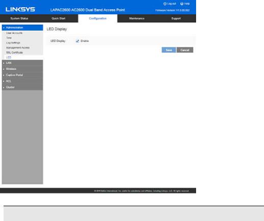
LED
Go to Configuration > Administration and select LED to enable or disable the LED on the top cover of LACAP2600.
LED
LED Display |
If disabled, the LED will be off even when the access |
|
point is working. By default, LED is enabled (on). |
|
|
23
LAN
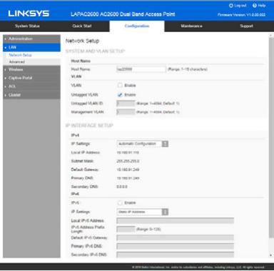
Network Setup
Go to Configuration > LAN > Network Setup to configure basic device settings, VLAN settings and settings for the LAN interface, including static or dynamic IPv4/IPv6 address assignment.
24

TCP/IP
Host Name |
Assign a host name to this access point. Host name consists of 1 to |
|
15 characters. Valid characters include A-Z, a-z, 0-9 and -. Character |
|
cannot be first and last character of hostname and hostname cannot |
|
be composed of all digits. |
|
|
VLAN |
Enables or disables VLAN function. |
|
|
Untagged |
Enables or disables VLAN tagging. If enabled (default), traffic from the |
VLAN |
LAN port is untagged when the following conditions are met: 1) VLAN |
|
ID is equal to Untagged VLAN ID and 2) untagged traffic can be |
|
accepted by LAN port. If disabled, traffic from the LAN port is always |
|
tagged and only tagged traffic can be accepted from LAN port. |
|
By default, all traffic on the access point uses VLAN 1, the default |
|
untagged VLAN. All traffic will be untagged until you disable the |
|
untagged VLAN, change the untagged traffic VLAN ID, or change the |
|
VLAN ID for a SSID. |
|
|
Untagged |
Specifies a number between 1 and 4094 for the untagged VLAN ID. |
VLAN ID |
The default is 1. Traffic on the VLAN that you specify in this field is |
|
not be tagged with a VLAN ID when forwarded to the network. |
|
Untagged VLAN ID field is active only when untagged VLAN is |
|
enabled. |
|
VLAN 1 is the default for both untagged VLAN and management |
|
VLAN. |
|
|
Management |
The VLAN associated with the IP address you use to connect to the |
VLAN |
access point. Provide a number between 1 and 4094 for the |
|
Management VLAN ID. The default is 1. |
|
|
IPv4/v6 |
|
|
|
IP Settings |
Select Automatic Configuration or Static IP Address. |
|
|
IP Address |
Enter an unused IP address from the address range used on your LAN. |
|
|
Subnet Mask |
Enter the subnet mask for the IP address above. |
|
|
Default |
Enter the gateway for the IP address above. |
Gateway |
|
|
|
Primary DNS |
Enter the DNS address. |
|
|
Secondary |
Optional. If entered, this DNS will be used if the Primary DNS does not |
DNS |
respond. |
|
|
25
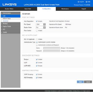
Advanced
Go to Configuration > LAN > Advanced to configure advanced network settings of the access point.
26

Port Settings
Auto |
If enabled, Port Speed and Duplex Mode will become grey |
Negotiation |
and cannot be configured. If disabled, Port Speed and |
|
Duplex Mode can be configured. |
|
Note—LAG (Link Aggregation) is enabled by default on |
|
Ethernet port 1 and 2. It is highly recommended you keep |
|
auto negotiation enabled on both sides of an aggregate |
|
link. Enable LACP (Link Aggregation Control Protocol) on |
|
this specific LAG interface when you create LAG interface |
|
on switch. If you have to disable auto negotiation, ensure |
|
link speed and duplex (Full) are identical on both sides. |
|
|
Operational |
Current Auto Negotiation mode of the Ethernet port. |
Auto |
|
Negotiation |
|
|
|
Port Speed |
Select the speed of the Ethernet port. Available only when |
|
Auto Negotiation is disabled. The option can be 10M, 100M |
|
or 1000M (default). |
|
|
Operational |
Displays the current port speed of the Ethernet port. |
Port Speed |
|
|
|
Duplex Mode |
Select the duplex mode of the Ethernet port. Available only |
|
when Auto Negotiation is disabled. The option can be Half |
|
or Full (default). |
|
|
Operational |
Displays the current duplex mode of the Ethernet port. |
Duplex Mode |
|
|
|
Flow Control |
Enable or disable flow control of the Ethernet port. |
|
|
27

802.1x Supplicant
802.1x |
Enable if your network requires this access point to use |
|
Supplicant |
802.1X authentication in order to operate. |
|
|
|
|
Authentication |
This feature supports following two kinds of authentication: |
|
|
• |
Authentication via MAC Address |
|
|
Select this if you want to use MAC Address for |
|
|
authentication. |
|
|
The access point uses lowercase MAC address for |
|
|
Name and Password, like xxxxxxxxxxxx. |
|
• |
Authentication via Name and Password |
|
|
Select this if you want to use name and password for |
|
|
authentication. |
|
|
Name - Enter the login name. The name includes 1 to 63 |
|
|
characters. Special characters are allowed. |
|
|
Password - Enter the desired login password. The |
|
|
password includes 4 to 63 characters. Special |
|
|
characters are allowed. |
|
|
|
Discovery Settings
Bonjour Enable if administrator wants the access point to be discovered by Bonjour enabled devices automatically. If VLAN is enabled, the discovery packets will be sent out via management VLAN only. The access point supports http and https services.
LLDP |
Enable if administrator wants the access point to be |
|
discovered by switch by LLDP protocol. Information such as |
|
product name, device name, firmware version, IP address, |
|
MAC address and so on will be advertised. |
|
|
LLDP-MED |
Enable if administrator wants the access point to be |
|
discovered by switch by LLDP-MED protocol. Information |
|
such as product name, device name, firmware version, IP |
|
address, MAC address and so on will be advertised. |
28

IGMP/MLD Snooping
IGMP |
IGMP (Internet Group Management Protocol) is a |
Snooping |
communications protocol used by hosts and adjacent |
|
routers on IP networks to establish multicast group |
|
memberships. IGMP is an integral part of IP multicast. |
|
IGMP snooping streamlines multicast traffic handling by |
|
examining (snooping) IGMP membership report messages |
|
from interested hosts, multicast traffic is limited to the |
|
subset of ports on which the hosts reside. |
|
IGMP snooping is enabled by default in the access point |
|
The access point supports IGMPv1, IGMPv2 and IGMPv3 in |
|
IGMP Snooping. |
|
|
MLD Snooping |
MLD (Multicast Listener Discovery) is a component of the |
|
Internet Protocol Version 6 (IPv6) suite. MLD is used by |
|
IPv6 routers for discovering multicast listeners on a |
|
directly attached link, much like IGMP is used in IPv4. |
|
Multicast Listener Discovery (MLD) Snooping provides |
|
multicast containment by forwarding traffic only to those |
|
clients that have MLD receivers for a specific multicast |
|
group (destination address). The access point maintains the |
|
MLD group membership information by processing MLD |
|
reports and generating messages so traffic can be |
|
forwarded to ports receiving MLD reports. |
|
MLD snooping is enabled by default in the access point |
|
The access point supports MLDv1 and MLDv2 in MLD |
|
Snooping. |
|
|
29
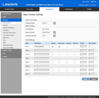
Wireless
Basic Settings
Go to Configuration > Wireless > Basic Settings to configure your wireless radio and SSIDs. Advanced wireless settings such as Band Steering, Channel Bandwidth, are on the Advanced Settings screen.
30
Loading...