


 Loading...
USER GUIDE
BUSINESS SERIES
Wireless-G Exterior
Access Point with
Power Over Ethernet
Model: WAP200E

About This Guide
About This Guide
Icon Descriptions
While reading through the User Guide you may encounter various icons designed to call attention to a specific item. Below is a description of these icons:
NOTE: This check mark indicates that there is a note of interest and is something that you should pay special attention to while using the product.
WARNING: This exclamation point indicates that there is a caution or warning and it is something that could damage your property or product.
WEB: This globe icon indicates a noteworthy website address or e-mail address.
Online Resources
Most web browsers allow you to enter the web address without adding the http:// in front of the address. This User Guide will refer to websites without including http:// in front of the address. Some older web browsers may require you to add it.
Resource |
Website |
|
|
Linksys |
www.linksys.com |
Linksys International |
www.linksys.com/international |
Glossary |
www.linksys.com/glossary |
Network Security |
www.linksys.com/security |
|
|
Copyright and Trademarks
Specifications are subject to change without notice. Linksys is a registered trademark or trademark of Cisco Systems, Inc. and/or its affiliates in the U.S. and certain other countries. Copyright © 2007 Cisco Systems, Inc. All rights reserved. Other brands and product names are trademarks or registered trademarks of their respective holders.
Wireless-G Exterior Access Point with Power Over Ethernet |
|

Table of Contents
Chapter 1: Introduction |
|
|
|
|
|
|
1 |
Chapter 2: Planning Your Wireless Network |
|
|
|
|
|
|
2 |
Network Topology . . . . . . . . . . . . |
. . . . |
. . . . . . . . |
. . |
. . |
. . |
|
2 |
Roaming . . . . . . . . . . . . . . . . |
. . . . |
. . . . . . . . |
. . |
. . |
. . |
|
2 |
Network Layout |
|
|
|
|
|
|
2 |
Example of a Simple Wireless Network . . . . |
. . . . |
. . . . . . . . |
. . |
. . |
. |
|
. 2 |
Chapter 3: Product Overview |
|
|
|
|
|
|
3 |
Front Panel |
|
|
|
|
|
|
3 |
Bottom Panel . . . . . . . . . . . . . . |
. . . . |
. . . . . . . . |
. . |
. . |
. . |
|
3 |
Top Panel |
|
|
|
|
|
|
3 |
Back Panel . . . . . . . . . . . . . . . . |
. . . . |
. . . . . . . . |
. . |
. . |
. |
|
. 4 |
The Antenna Pattern . . . . . . . . . . . |
. . . . |
. . . . . . . . |
. . |
. . |
. |
. |
4 |
Chapter 4: Installation |
|
|
|
|
|
|
6 |
Overview |
|
|
|
|
|
|
6 |
Personal Installation . . . . . . . . . . . . . . |
. . . . . . |
. . . . . . . . . . . . |
. . . |
. . . |
. . |
. |
6 |
Installation Location |
|
|
|
|
|
|
6 |
External Antenna |
|
|
|
|
|
|
6 |
Installation Procedure |
|
|
|
|
|
|
6 |
Chapter 5: Quick Configuration Overview |
|
|
|
|
|
|
8 |
Overview |
|
|
|
|
|
|
8 |
Accessing the Web-Based Utility . . . . . . |
. . . . |
. . . . . . . . |
. . |
. . |
. . |
|
8 |
Navigating the Web-Based Utility . . . . . . |
. . . . |
. . . . . . . . |
. . |
. . |
. |
|
. 8 |
Setup . . . . . . . . . . . . . . . . |
. . . . |
. . . . . . . . |
. . |
. . |
. |
|
. 8 |
Wireless |
|
|
|
|
|
|
8 |
AP Mode . . . . . . . . . . . . . . |
. . . . |
. . . . . . . . |
. . |
. . |
. . |
|
9 |
Administration . . . . . . . . . . . . |
. . . . |
. . . . . . . . |
. . |
. . |
. |
|
. 9 |
Status . . . . . . . . . . . . . . . . |
. . . . |
. . . . . . . . |
. . |
. . |
. |
|
. 9 |
Chapter 6: Advanced Configuration |
|
|
|
|
|
10 |
|
Web-Based Utility . . . . . . . . . . . . |
. . . . |
. . . . . . . . |
. . |
. . |
. . |
|
10 |
Setup > Basic Setup . . . . . . . . . . . . |
. . . . |
. . . . . . . . |
. . |
. . |
. |
|
10 |
Setup . . . . . . . . . . . . . . . . |
. . . . |
. . . . . . . . |
. . |
. . |
. |
|
10 |
Network Setup . . . . . . . . . . . . |
. . . . |
. . . . . . . . |
. . |
. . |
. |
|
10 |
Setup > Time . . . . . . . . . . . . . . |
. . . . |
. . . . . . . . |
. . |
. . |
. . |
|
11 |
Time . . . . . . . . . . . . . . . . |
. . . . |
. . . . . . . . |
. . |
. . |
. . |
|
11 |
Wireless > Basic Wireless Settings . . . . . . |
. . . . |
. . . . . . . . |
. . |
. . |
. |
|
11 |
Basic Settings . . . . . . . . . . . . |
. . . . |
. . . . . . . . |
. . |
. . |
. . |
|
11 |
Wireless > Wireless Security . . . . . . . . |
. . . . |
. . . . . . . . |
. . |
. . |
. . |
|
12 |
Wireless Security . . . . . . . . . . . |
. . . . |
. . . . . . . . |
. . |
. . |
. |
.12 |
|
Wireless > Wireless Connection Control . . . |
. . . . |
. . . . . . . . |
. . |
. . |
. |
.15 |
|
Wireless-G Exterior Access Point with Power Over Ethernet |
ii |

Table of Contents
Wireless Connection Control . . . . . . . . . . |
. . . . . . . . . . . . |
. |
15 |
Connection Control . . . . . . . . . . . . . . |
. . . . . . . . . . . . |
. |
15 |
Connection Control List |
|
|
16 |
Wireless > Advanced Wireless Settings . . . . . . . . |
. . . . . . . . . . . . |
. |
16 |
Advanced Settings |
|
|
16 |
Wireless > VLAN & QoS . . . . . . . . . . . . . . |
. . . . . . . . . . . . |
. . |
17 |
VLAN |
|
|
17 |
QoS . . . . . . . . . . . . . . . . . . . . |
. . . . . . . . . . . . |
. . |
17 |
AP Mode . . . . . . . . . . . . . . . . . . . . |
. . . . . . . . . . . . |
. . |
18 |
Administration > Management |
|
|
19 |
AP Password |
|
|
19 |
Web Access . . . . . . . . . . . . . . . . . |
. . . . . . . . . . . . |
. |
.19 |
SNMP . . . . . . . . . . . . . . . . . . . . |
. . . . . . . . . . . . |
. |
19 |
Administration > Log . . . . . . . . . . . . . . . |
. . . . . . . . . . . . |
. |
.20 |
Log |
|
|
20 |
Administration > Factory Default . . . . . . . . . . |
. . . . . . . . . . . . |
. |
21 |
Factory Default . . . . . . . . . . . . . . . . |
. . . . . . . . . . . . |
. |
21 |
Administration > Firmware Upgrade . . . . . . . . |
. . . . . . . . . . . . |
. . |
21 |
Firmware Upgrade . . . . . . . . . . . . . . |
. . . . . . . . . . . . |
. . |
21 |
Administration > Reboot |
|
|
22 |
Reboot . . . . . . . . . . . . . . . . . . . |
. . . . . . . . . . . . |
. |
.22 |
Administration > Config Management . . . . . . . . |
. . . . . . . . . . . . |
. |
22 |
Config Management |
|
|
22 |
Status > Local Network . . . . . . . . . . . . . . . . . . . . . . . . . . . . . . . . . . . . . . . . . .22 |
|||
Information . . . . . . . . . . . . . . . . . |
. . . . . . . . . . . . |
. |
.22 |
Local Network |
|
|
22 |
Status > Wireless . . . . . . . . . . . . . . . . . |
. . . . . . . . . . . . |
. |
.23 |
Wireless Network |
|
|
23 |
Status > System Performance |
|
|
23 |
System Performance |
|
|
23 |
Appendix A: Troubleshooting |
|
|
25 |
Appendix B: Wireless Security Checklist |
|
|
28 |
General Network Security Guidelines |
|
|
28 |
Additional Security Tips . . . . . . . . . . . . . . |
. . . . . . . . . . . . |
. |
28 |
Appendix C: Glossary |
|
|
29 |
Appendix D: Specifications |
|
|
33 |
Appendix E: Warranty and Regulatory Information |
|
|
35 |
Limited Warranty |
|
|
35 |
FCC Statement . . . . . . . . . . . . . . . . . . |
. . . . . . . . . . . . |
. |
35 |
Wireless-G Exterior Access Point with Power Over Ethernet |
iii |

Table of Contents
FCC Radiation Exposure Statement . . . . . . . . . . . . . . . . . . . . .36
Safety Notices |
36 |
Industry Canada Statement . . . . . . . . . . . . . . . . . . . . . . . . |
. . 36 |
Industry Canada Radiation Exposure Statement: |
36 |
Avis d’Industrie Canada |
36 |
Avis d’Industrie Canada concernant l’exposition aux radiofréquences : |
36 |
User Information for Consumer Products Covered by EU Directive 2002/96/EC on Waste |
|
Electric and Electronic Equipment (WEEE) |
37 |
Appendix F: Contact Information |
41 |
Wireless-G Exterior Access Point with Power Over Ethernet |
iv |

Chapter 1 |
Introduction |
Chapter 1:
Introduction
Thank you for choosing the Wireless-G Exterior Access Point with Power Over Ethernet.
The Linksys Wireless-G Exterior Access Point with Power Over Ethernet lets you connect Wireless-G (802.11g) or Wireless-B (802.11b) devices to your wired network so you can add PCs to the network with no cabling hassle. This weather-proof Access Point creates a “wireless bubble” in exterior spaces, like patios, pool areas, and outdoor cafés. Power over Ethernet support makes it easy to install, and you can create multiple SSIDs that connect to individual VLANs to keep your traffic separated.
It’s also perfect for use as a bridge, a kind of “cable-less cable” to connect remote areas together. Maybe your warehouse is in a separate building from your offices. Or maybe you need to connect the separate buildings of a college campus. With one Wireless-G Exterior Access Point on each building, you’re connected with no cable to run. The exterior-rated case protects the access point, and contains an internal antenna.
To protect your data and privacy, the Wireless-G Exterior Access Point with Power Over Ethernet supports both Wired Equivalent Privacy (WEP) and the industrial-strength wireless security of Wi-Fi Protected Access™ (WPA), encoding all your wireless transmissions with powerful encryption. The MAC Address filter lets you decide exactly who has access to your wireless network, and advanced logging keeps you appraised. Configuration is a snap with the web browser-based configuration utility.
The Linksys Wireless-G Exterior Access Point with Power Over Ethernet is the best way to add wireless access to the outdoor areas of your home or business.
Wireless-G Exterior Access Point with Power Over Ethernet |
|

Chapter 2
Chapter 2:
Planning Your Wireless
Network
Network Topology
A wireless network is a group of computers, each equipped with one or more wireless adapters. Computers in a wireless network must be configured to share the same radio channel to talk to each other. Several PCs equipped with wireless cards or adapters can communicate with each other to form an ad-hoc network without the use of an access point.
Linksys wireless adapters also provide access to a wired network when using an access point or wireless router. An integrated wireless and wired network is called an infrastructurenetwork.EachwirelessPCinaninfrastructure network can talk to any computer in a wired or wireless network via the access point or wireless router.
An infrastructure configuration extends the accessibility of a wireless PC to a wired network, and may double the effective wireless transmission range for two wireless adapter PCs. Since an access point is able to forward data within a network, the effective transmission range in an infrastructure network may be doubled (depending on antenna characteristics).
Roaming
Infrastructure mode also supports roaming capabilities for mobile users. Roaming means that you can move your wireless PC within your network and the access points will pick up the wireless PC’s signal, providing that they both share the same wireless channel, SSID, and wireless security settings.
Before you consider roaming, choose a feasible radio channel and optimum access point position. Proper access point positioning combined with a clear radio signal will greatly enhance performance.
NOTE: Spanning Tree Protocol should be disabled on the switches connecting to the APs to allow roaming to work without disruption.
Network Layout
The Access Point has been designed for use with 802.11g and 802.11b products, such as the Notebook Adapters for your laptop computers, PCI Adapters for your desktop PCs, and USB Adapters.
Planning Your Wireless Network
These wireless products can also communicate with a 802.11g or 802.11b Wireless PrintServer.
To link your wired network with your wireless network, connect the Access Point’s Ethernet network port to any switch or router with Power over Ethernet (PoE)—or a PoE injector, such as the Linksys WAPPOE or WAPPOE12.
NOTE: 12 VDC on WAPPOE12 is for the splitter output. Both PoE Injectors provide 48 VDC power output.
Go to the Linksys website at www.linksys.com for more information about wireless products.
Example of a Simple Wireless Network
Example of Simple Wireless Network
The above diagram shows a typical infrastructure wireless network setup. The Wireless Access Points are connecting to a Linksys switch that provides power to the Access Points. Each Access Point can connect multiple wireless devices to the network. This network will provide connectivity among wireless network devices and PCs that have a wired connection to the switch.
The switch then can connect to a router that can connect to an ISP for Internet access.
Wireless-G Exterior Access Point with Power Over Ethernet |
|

Chapter 3
Chapter 3:
Product Overview
Front Panel
The Access Point’s LEDs, where information about network activity is displayed, are located on the front panel.
Front Panel
Power (Green) The Power LED lights up when the Access Point is powered on.
Wired (Green) The Wired LED lights up when the Access Point is successfully connected to a device through the Ethernet network port. If the Wired LED is flashing, the Access Point is actively sending to or receiving data from one of the devices over the Ethernet network port.
Wireless (Green) The Wireless LED lights up when the wireless module is active on the Access Point. If the Wireless LED is flashing, the Access Point is actively sending to or receiving data from a wireless device.
Product Overview
Bottom Panel
The Ethernet network port is located on the bottom panel of the Access Point.
Bottom Panel
Ethernet network port The Ethernet network port connects to Ethernet network devices, such as a switch or router. The Access Point is powered using Power Over Ethernet. If the switch or router doesn’t support Power Over Ethernet, then a Power Over Ethernet Injector must be installed.
Top Panel
The antenna port is located on the top panel of the Access Point.
Top Panel
Antenna Port The Access Point has built-in,  1x2 MIMO 9dBi directional antennas. It also has a reverse polarity female N-type antenna port for an optional, high gain external antenna such as the HGA9N. One of the two internal antennas will be disabled automatically when
an external antenna is connected.
Wireless-G Exterior Access Point with Power Over Ethernet |
|

Chapter 3 |
Product Overview |
Back Panel
The Access Point’s Reset button and ground are located on the back panel.
Reset button
 Ground
Back Panel
Reset Button There are two ways to Reset the Access Point’s factory defaults. Either press the Reset button, for approximately ten seconds, or restore the defaults using the Access Point’s web-based utility.
IMPORTANT: Resetting the Access Point will erase all of your settings (including wireless security, IP address, and power output) and replace them with the factory defaults. Do not reset the Access Point if you want to retain these settings.
Ground Before you mount the Access Point, you must ground the Access Point (to a large piece of metal) as a precaution against electric shock.
The Antenna Pattern
The Wireless-G Exterior Access Point uses 1X2 MIMO (1Tx, 2Rx) so it has two built in antennas. The right antenna is the main antenna for Tx traffic. When an external antenna is attached, the right antenna is disabled and the external antenna is used for Tx traffic. Currently, only the HGA9N (9dBi omni directional antenna) is compatible with the Wireless-G Exterior Access Point.
Right Antenna Pattern
3dB BW: 50 degree, peak gain: 6.3 dBi
Left Antenna Pattern
3dB BW: 63 degree, peak gain: 4.9 dBi
Wireless-G Exterior Access Point with Power Over Ethernet |
|
Chapter 3 |
Product Overview |
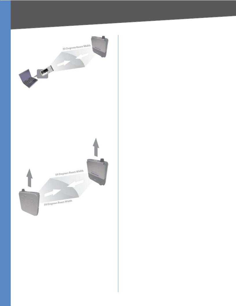
Radio Coverage of the Access Point to Client Devices
When using the Access Point to connect client devices, adjust it so the client devices are on the same horizontal plane as the Access Point and within a 3dB angle of 50 degrees. This will ensure the strongest signal and maximum reach.
If the Access Point is used inside a building, put it in a corner of the building for maximum coverage.
Access Point to Access Point (bridging) Radio Coverage
If the Access Point is used as a bridge or repeater, adjust the Access Points so they face each other, this will ensure the strongest signal and maximum reach.
Make sure that the orientation of the two Directional Antennas is the same. The radio wave is polarized so a 90 degree rotation will result in no received power.
Due to its directional characteristics, the internal antenna is ideal for point-to-point bridge mode or the spoke side of point-to-multipoint bridge mode. An external omni directional antenna (e.g. HGA9N) is recommended for repeater mode applications.
Wireless-G Exterior Access Point with Power Over Ethernet |
|
Chapter 4
Chapter 4:
Installation
Overview
This chapter explains how to mount and connect the Access Point.
Depending on your application, you might want to set up the IP address of the device first before mounting the device. Refer to “Chapter 5: Quick Configuration Overview”.
Personal Installation
This product should be installed by a qualified installation professional with RF and related rule knowledge. General users should not attempt to install this product or modify the settings.
Installation Location
The product should be installed in a location where the radiating antenna is at least 20 cm from anyone under normal operating conditions. This is required to meet regulatory RF exposure requirements.
External Antenna
UseonlyantennasapprovedbyLinksys.Antennasthathave not been approved by Linksys may produce unwanted spurious or excessive RF transmitting power, this may lead to violation of FCC limitations and is prohibited.
Installation Procedure
Follow the Hardware Installation instructions for details on installing this product.
WARNING: Please carefully select the installation position and make sure that the final output power does not exceed the limit defined in US Rule CFR 47 Part 15, section 15.247 and 15.407. Violation of the rule could lead to serious federal penalties.
Hardware Installation
1.Locate an optimum location on a wall for the Access Point. Refer to the antenna pattern in “Chapter 3: Product Overview” to adjust the angle of the Access Point for your application.
Installation
2.Using the mounting plate as a template, mark the locations of the two wall-mount slots that are on the bottom of the mounting plate. Then, install a screw into each location.
Mark the Locations of the Two Wall-Mount Slots
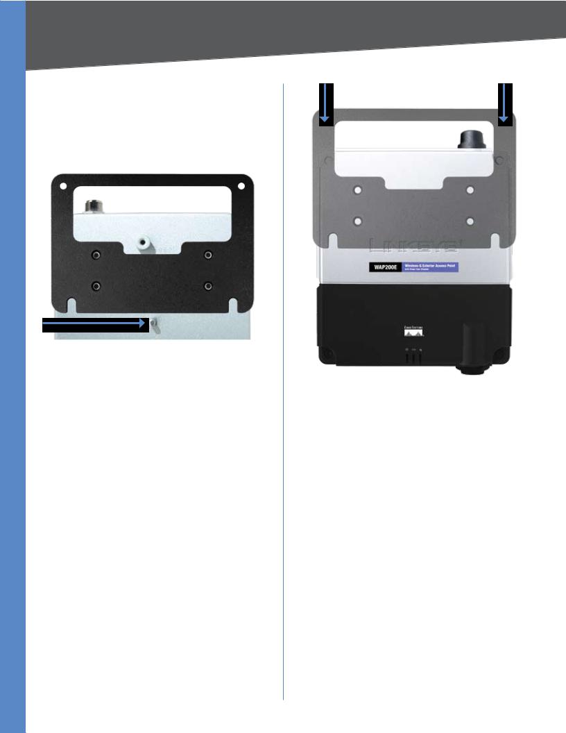
3.Use four screws (included with the Access Point) to attach the mounting plate to the back panel of the Access Point.
Attach the Mounting Plate
4.Connect the included Category 5e Ethernet network cable to the Ethernet network port of the Access Point.
Wireless-G Exterior Access Point with Power Over Ethernet |
|
Chapter 4 |
Installation |
Then, screw the connector cap tightly onto the port, so the Access Point has a water-resistant seal.
5.If you want to connect an optional, high-gain external antenna, remove the cap that protects the antenna port, then, connect your antenna cable to this port.
6.Make sure that you properly ground the Access Point.
Ground the Access Point
7.Line up the Access Point’s wall-mount slots with the two screws on the wall. Then, slide the Access Point down so that the screws fit snugly in the slots.
8.Attach a screw (not included) in each of the two holes on the top of the mounting plate so that the Access Point is securely mounted to the wall.
Attach the Access Point to the Wall
9.Connect the other end of the Ethernet network cable to a switch, router, or other device that supports Power over Ethernet. The Access Point will then be connected to your wired network.
Now that the hardware installation is complete, proceed to “Chapter 5: Quick Configuration Overview” for directions on how to configure the Access Point.
Wireless-G Exterior Access Point with Power Over Ethernet |
|

Chapter 5
Chapter 5:
Quick Configuration
Overview
Overview
The Access Point has been designed to be functional right out of the box with the default settings. However, if you’d like to change these settings, the Access Point can be configured through your web browser with the web based utility. This chapter explains how to use the utility.
The utility can be accessed via web browsers, such as Microsoft Internet Explorer or Mozilla Firefox through the use of a computer that is networked with the Access Point.
For a basic network setup, most users only have to use the following screens of the Utility:
•Setup On the Setup screen, enter your basic network settings (IP address) here.
•Management Click the Administration tab and then select the Management screen. The Access Point’s default password is admin. To secure the Access Point, change the AP Password from its default.
Most users will also customize their wireless settings:
•Wireless On the Wireless screen, change default SSID under the Basic Wireless Settings tab. Select the level of security under the Wireless Security tab.
Accessing the Web-Based Utility
There are two ways to power your Access Point.
•48V Power Injector (e.g. Linksys WAPPOE) Power up your Access Point first then connect the cable on your Injector to your PC.
•PoE switch (e.g. Linksys SRW224P) Connect your Access Point and your PC to the same LAN.
To access the web-based utility, perform the following steps:
1.Configure your PC with a static IP address in the same subnet as the Access Point’s default IP address (192.168.1.245). If there is DHCP server connected to the switch, configure it to assign the IP address in 192.168.1.0/24 subnet. Your PC will get an IP address in the subnet through the DHCP.
Quick Configuration Overview
2.Launch your web browser, such as Internet Explorer or Mozilla Firefox and enter the Access Point’s default IP address, 192.168.1.245, in the Address field. Press the Enter key.
3.Enter admin in the User Name field. The first time you open the Web-based Utility, use the default password, admin. (You can set a new password from
Administration > Management) Then click the OK button.
After setting up the Access Point to use DHCP or manually configure a new IP address, move your Access Point to the desired network. You will have to use the new IP address the next time you access the Web-based Utility.
Navigating the Web-Based Utility
The web-based utility consists of the following five main tabs: Setup, Wireless, AP Mode, Administration, and
Status. Additional screens (sub tabs) will be available from most of the main tabs.
The following briefly describes the main and sub tabs of the Utility.
Setup
Basic Setup Enter the Host Name and IP Address settings on this screen.
Time Youcansetthetimeeithermanuallyorautomatically from a time server if the Access Point can access the public Internet.
Wireless
You will use the Wireless tabs to enter a variety of wireless settings for the Access Point.
Basic Wireless Settings Choose the wireless network mode (e.g. wireless-G), wireless channel, and SSID configuration on this screen.
Wireless Security Use this screen to configure the Access Point’s security settings including access authentication, data encryption, and wireless isolation.
Wireless Connection Control Use this screen to populate your Access List to permit or block certain MAC address access to your wireless network.
AdvancedWireless Settings Use this screen to configure the Access Point’s more advanced wireless settings such as Beacon interval, Output Power, etc.
VLAN & QoS Use this screen to configure the VLAN and QoS related settings for the Access Point.
Wireless-G Exterior Access Point with Power Over Ethernet |
|

Chapter 5 |
Quick Configuration Overview |
AP Mode
Use this screen to configure the Access Point operation mode with WDS (Wireless Distribution System).
Administration
You will use the Administration tabs to manage the Access Point.
Management This screen allows you to customize the password and Simple Network Management Protocol (SNMP) settings.
Log Configure the Log settings for the Access Point on this screen.
Factory Default Use this screen to reset the Access Point to its factory default settings.
Firmware Upgrade Upgrade the Access Point’s firmware on this screen.
Reboot Use this screen to reboot the Access Point.
Config Management You can back up the configuration file for the Access Point, as well as save the backup configuration file to the Access Point.
Status
You will be able to view status information for your local network, wireless networks, and network performance.
Local Network This screen displays system information, including software & hardware version, MAC address, and IP address on the LAN side of the Access Point.
Wireless This screen displays wireless network settings including SSID, network mode, and wireless channel.
System Performance This screen displays the current traffic statistics of the Access Point’s Wireless and LAN ports.
Wireless-G Exterior Access Point with Power Over Ethernet
Loading...