


 Loading...
USER GUIDE
Powerline Network Adapter,
Powerline 4-Port Network Adapter,
Powerline Network Kit
Model: PLTE200, PLTS200, PLTK300

About This Guide
About This Guide
Icon Descriptions
While reading through the User Guide you may see various icons that call attention to specific items. Below is a description of these icons:
NOTE: This check mark indicates that there is a note of interest and is something that you should pay special attention to while using the product.
WARNING: This exclamation point indicates that there is a caution or warning and it is something that could damage your property or product.
WEB: This globe icon indicates a noteworthy website address or e-mail address.
Online Resources
Website addresses in this document are listed without http:// in front of the address because most current web browsers do not require it. If you use an older web browser, you may have to add http:// in front of the web address.
Resource |
Website |
|
|
Linksys |
www.linksys.com |
|
|
Linksys International |
www.linksys.com/international |
|
|
Glossary |
www.linksys.com/glossary |
|
|
Network Security |
www.linksys.com/security |
|
|
Copyright and Trademarks
Linksys, Cisco and the Cisco Logo are registered trademarks or trademarks of Cisco Systems, Inc. and/or its affiliates in the U.S. and certain other countries. Copyright © 2008 Cisco Systems, Inc. All rights reserved. Other brands and product names are trademarks or registered trademarks of their respective holders.
Powerline Network Adapter |
i |

Table of Contents
Chapter 1: Introduction to Powerline Networking |
|
|
1 |
How Powerline Networking Works |
|
|
1 |
How to Share Internet Access over the Powerline Network . . . . . . . . |
. . |
. . |
. 1 |
A Powerline Network in a Two-Story House . . . . . . . . . . . . . . |
. . . |
. . |
. 2 |
Chapter 2: Product Overview |
|
|
3 |
Front Panel of the Powerline Network Adapter (model number: PLTE200) |
|
|
3 |
Ports Panel of the Powerline Network Adapter (model number: PLTE200) |
|
|
3 |
Front Panel of the Powerline 4-Port Network Adapter (model number: PLTS200) . . . . 3
Ports Panel of the Powerline 4-Port Network Adapter (model number: PLTS200) . . |
. |
. 4 |
Placement Options . . . . . . . . . . . . . . . . . . . . . . . . . . . . |
. |
. 4 |
Chapter 3: Advanced Configuration |
|
6 |
Overview |
|
6 |
How to Install the Powerline Utility . . . . . . . . . . . . . . . . . . . . . . |
. |
6 |
How to Access the Powerline Utility |
|
6 |
Main |
|
7 |
Security |
|
8 |
Diagnostics . . . . . . . . . . . . . . . . . . . . . . . . . . . . . . . . |
. |
9 |
About . . . . . . . . . . . . . . . . . . . . . . . . . . . . . . . . . . |
. |
. 9 |
Appendix A: Troubleshooting |
10 |
|
Appendix B: Specifications |
11 |
|
Appendix C: Warranty Information |
12 |
|
Limited Warranty |
|
12 |
Appendix D: Regulatory Information |
14 |
|
FCC Statement . . . . . . . . . . . . . . . . . . . . . . . . . . . . . . |
. |
14 |
Safety Notices |
|
14 |
Industry Canada Statement . . . . . . . . . . . . . . . . . . . . . . . . . |
. |
14 |
User Information for Consumer Products Covered by EU Directive 2002/96/EC on Waste |
||
Electric and Electronic Equipment (WEEE) |
|
15 |
Appendix E: Software License Agreement |
19 |
|
Software in Linksys Products . . . . . . . . . . . . . . . . . . . . . . . . |
. |
19 |
Software Licenses . . . . . . . . . . . . . . . . . . . . . . . . . . . . . |
. |
19 |
Powerline Network Adapter |
ii |

Chapter 1
Introduction to Powerline Networking
Chapter 1: Introduction to Powerline Networking
How Powerline Networking Works
Powerlines run through your home or office, carrying electrical power to electrical outlets in every room.
The typical wired Ethernet network uses Ethernet network cables to connect your wired network devices. A powerline network uses your existing powerlines as the wiring for your powerline network.
To create your powerline network, use Powerline Adapters. Each device on your powerline network requires connection to a Powerline Adapter.
The Powerline Network Adapter (model number: PLTE200) features one Ethernet port and connects to the following:
•• an electrical outlet
•• a computer or other Ethernet network device (using an Ethernet cable)
The Powerline 4-Port Network Adapter (model number: PLTS200) features four Ethernet ports and connects to the following:
•• an electrical outlet
•• up to four computers or other Ethernet network devices (using Ethernet cables)
Powerline
Network Adapter
Internet
Powerline
Modem
Router
How to Share Internet Access over the Powerline Network
To share Internet access over the powerline network, add your router to the powerline network. Connect a Powerline Adapter to one of the local Ethernet network ports on your router. Then connect the Powerline Adapter to an electrical outlet.
The diagram below shows the connections of a basic powerline network.The connections between the Internet, modem, and router stay the same.
Using an Ethernet network cable, the router is connected to its Powerline Adapter, which is plugged into an electrical outlet.
Using Ethernet network cables, the gaming console and computer are connected to their Powerline 4-Port Network Adapter, which is plugged into an electrical outlet.
Computer
Powerline 4-Port
Network Adapter
Gaming Console
Connection Diagram of a Basic Powerline Network
Powerline Network Adapter |
1 |
Chapter 1
Introduction to Powerline Networking
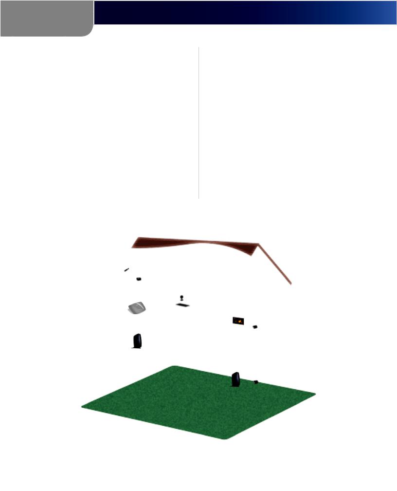
A Powerline Network in a Two-Story House
This diagram shows a basic powerline network in a two-story house. The router upstairs is connected to its Powerline Adapter, which is plugged into an electrical outlet. Downstairs, the gaming console and a computer share their Powerline 4-Port Network Adapter, which is plugged into an electrical outlet.
Using the powerlines of the home, the router expands your local network to include the gaming console and desktop computer in the living room. Internet access and files can be shared between your computers and other networked devices.
For online gaming, you can play downstairs in the comfort of your living room, while taking advantage of your router and high-speed Internet connection upstairs.
Internet
Modem Router
Powerline
Network Adapter
Computer
Powerline 4-Port
Gaming Network Adapter
Console
Diagram of a Powerline Network in a Two-Story House
Powerline Network Adapter |
2 |
Chapter 2
Product Overview
Chapter 2:
Product Overview
Thank you for choosing the Linksys by Cisco powerline products: Powerline Network Adapter (model number: PLTE200), Powerline 4-Port Network Adapter (model number: PLTS200), or Powerline Network Kit (model number: PLTK300).
The Powerline Network Adapter features one Ethernet port to connect a router, computer, or other network device to your powerline network, while the Powerline 4-Port Network Adapter features four Ethernet ports to connect up to four computers or other network devices to your powerline network.
The Kit features one Powerline Network Adapter and one
Powerline 4-Port Network Adapter to create a powerline network. Connect the Powerline Network Adapter to your network router, and connect the Powerline 4-Port Network Adapter to computers or other network devices.
For more information about powerline networking, refer to “Chapter 1: Introduction to Powerline Networking”.
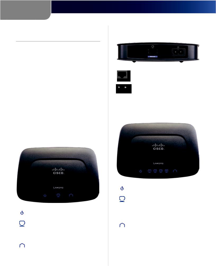
Front Panel of the Powerline Network Adapter (model number: PLTE200)
Power (Blue) The power LED lights up when the Powerline Adapter is powered on.
Ethernet (Blue) The Ethernet LED lights up when the Powerline Adapter is connected to a network device through the Ethernet port. The LED flashes to indicate network activity over that port.
Powerline (Blue) The Powerline LED lights up when the Powerline Adapter is connected to the powerline network through the Power port. The LED flashes to indicate network activity over that port.
Ports Panel of the Powerline Network Adapter (model number: PLTE200)
Ethernet The Ethernet port connects to an Ethernet network device, such as a router or computer.
Power The Power port connects to the powerline end of the power cord.
Front Panel of the Powerline 4-Port Network Adapter (model number: PLTS200)
Power (Blue) The power LED lights up when the Powerline Adapter is powered on.
Ethernet (Blue) These numbered LEDs correspond with the numbered Ethernet ports on the back panel. A LED lights up when its corresponding port is connected to a network device. It flashes to indicate network activity over that port.
Powerline (Blue) The Powerline LED lights up when the Powerline Adapter is connected to the powerline network through the Power port. The LED flashes to indicate network activity over that port.
Powerline Network Adapter |
3 |
Chapter 2
Product Overview
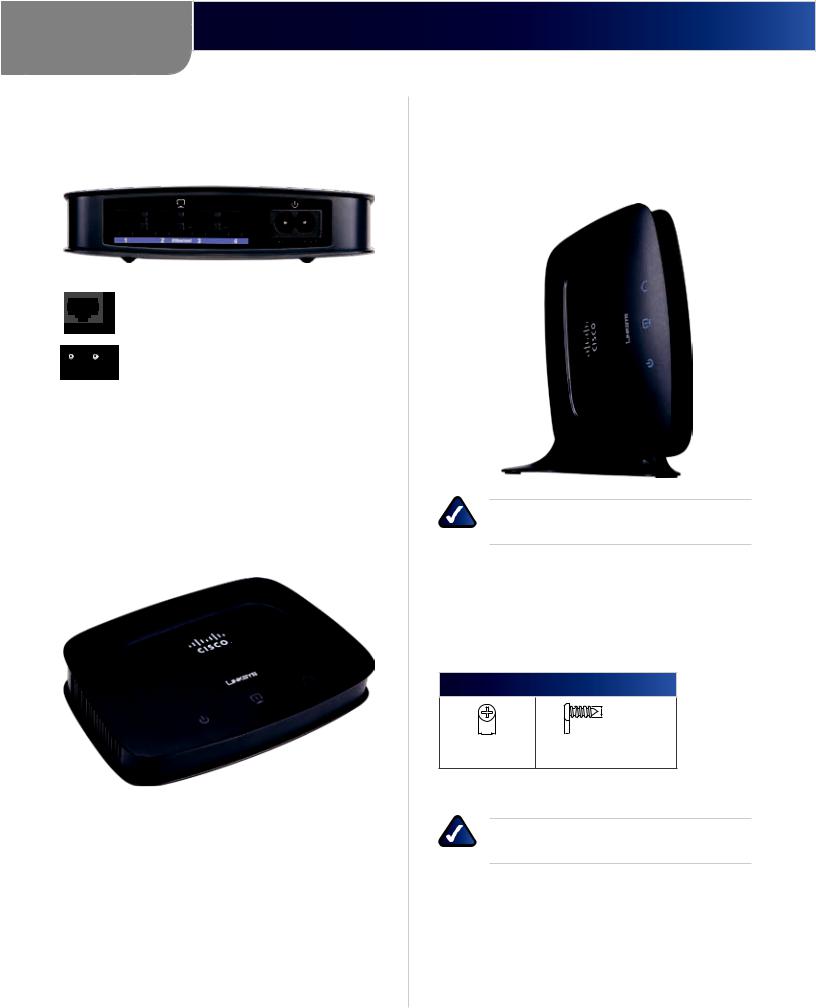
Ports Panel of the Powerline 4-Port Network Adapter (model number: PLTS200)
Ethernet 1-4 These Ethernet ports (1, 2, 3, 4) connect to computers or other network devices.
Power The Power port connects to the powerline end of the power cord.
Placement Options
There are three ways to place the Powerline Adapter. The first way is horizontal placement on a surface. The second way is vertical placement on a stand. The third way is wallmounting.
Horizontal Placement
Place the Powerline Adapter on a level surface near an electrical outlet.
Vertical Placement
The stand fits only on the side panel adjacent to the Power port. Insert the stand into the side panel, and then place the Powerline Adapter on a level surface near an electrical outlet.
NOTE: When the Powerline Adapter is on the stand, the Power port is closest to the stand.
Wall-Mounting Placement
ThePowerlineAdapterhasfourwall-mountslotsonitsback panel. The distance between two adjacent slots is 60 mm (2.36 inches).
Two screws are needed to mount the Powerline Adapter.
Suggested Mounting Hardware
4 mm |
1-1.5 mm |
2-2.5 mm |
††Note: Mounting hardware illustrations are not true to scale.
NOTE: Linksys is not responsible for damages incurred by insecure wall-mounting hardware.
Follow these instructions:
1.Determine where you want to mount the Powerline Adapter. Make sure that the wall you use is smooth, flat, dry, and sturdy. Also make sure the location is within reach of an electrical outlet.
2.Drill two holes into the wall. Make sure the holes are 60 mm (2.36 inches) apart.
Powerline Network Adapter |
4 |
Chapter 2
Product Overview
3.Insert a screw into each hole and leave 3 mm (0.12 inches) of its head exposed.
4.Maneuver the Powerline Adapter so the two wallmount slots line up with the two screws.
5.Place the wall-mount slots over the screws and slide the Powerline Adapter down until the screws fit snugly into the wall-mount slots.
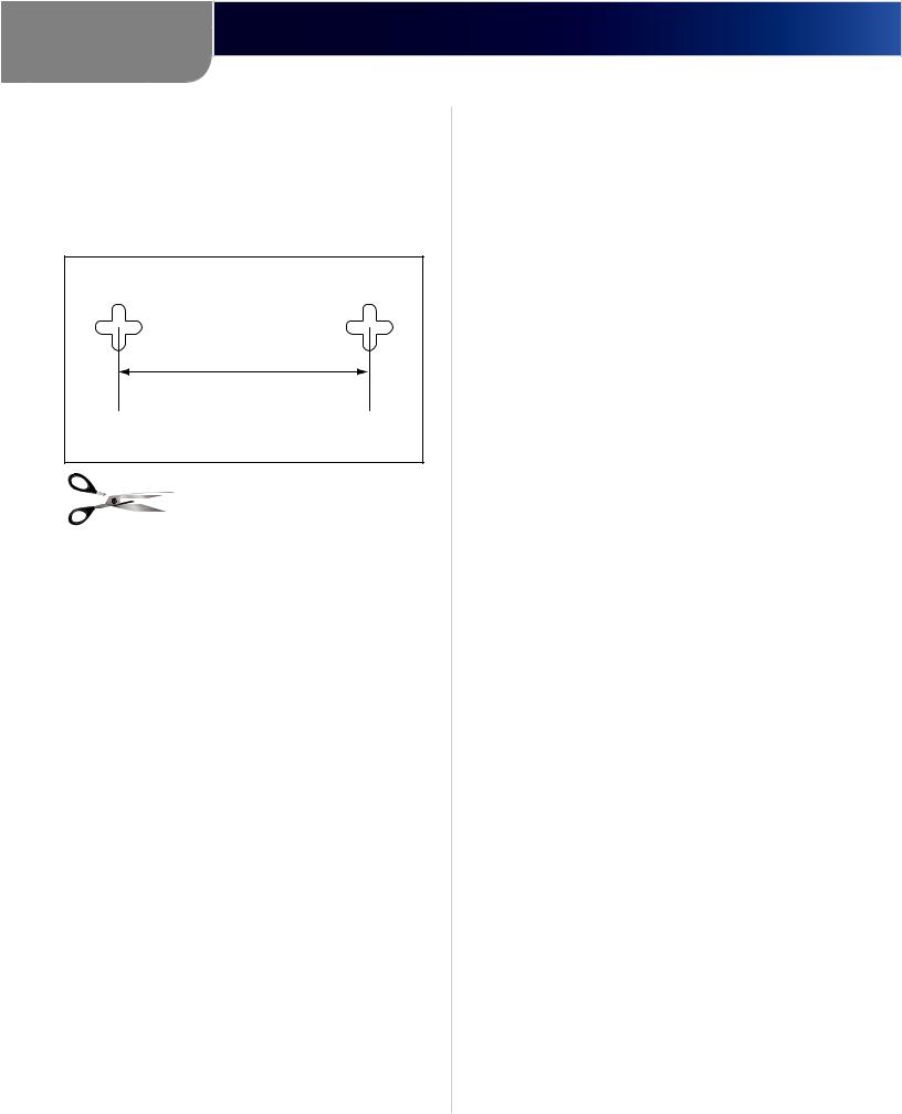
60 mm
Wall Mounting Template
Print this page at 100% size, and cut along the dotted line. Check the template’s accuracy by measuring the distance between the wall-mount slots with a ruler. This distance should be 60 mm. Then place the template on the wall to drill precise spacing.
Powerline Network Adapter |
5 |

Chapter 3
Advanced Configuration
Chapter 3:
Advanced Configuration
Overview
Use the Powerline Utility to configure advanced security for your powerline network.
How to Install the Powerline Utility
1.Insert the included CD-ROM into the CD-ROM drive of your computer.
2.Go to Start > Run.
3.In the Open field, enter D:\setup.exe (if “D” is the letter of your CD drive). Then click OK.
4.The Welcome screen appears. Click Next.
Welcome Screen
5. To accept the License Agreement, click Yes.
License Agreement
6. To install the Powerline Utility in the default folder, click Next.
To select a different folder, click Browse, and select the new location. Then click Next.
Choose Destination Location
7. When the installation is complete, click Finish.
InstallShield Wizard Complete
How to Access the Powerline Utility
After installation, the icon for the Powerline Utility appears on your desktop.
Powerline Utility Icon
Double-click the icon to open the Powerline Utility.
Powerline Network Adapter |
6 |
Chapter 3
Advanced Configuration
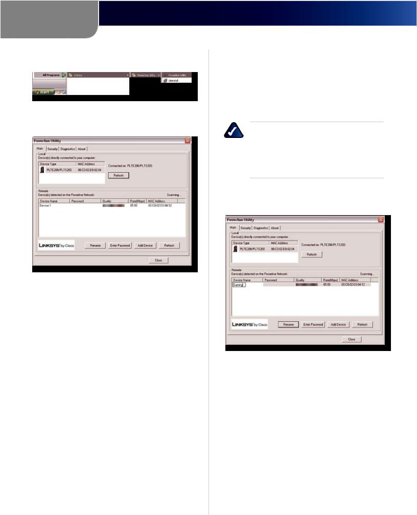
You can also go to Start > Programs > Linksys > Powerline Utility.
Start > Programs > Linksys > Powerline Utility
When the Powerline Utility opens, the Main screen appears.
Main Screen
You have four screens available:
Main Detect, rename, add or access Powerline Adapters.
Security Set a Network Password to configure advanced security for your powerline network. (The Network Password is a key used to encrypt communications between the Powerline Adapters.)
Diagnostics View information about the Powerline Adapters.
About View information about the Powerline Utility. Click Close to exit the Powerline Utility.
Main
Use this screen to detect, rename, add, or access remote Powerline Adapters.
Local
The Powerline Adapter connected directly to your computer is listed with its Device Type and MAC Address.
Refresh Click this option to update the status information of the local Powerline Adapter.
Remote
The remote Powerline Adapters are listed with the following information: Device Name, (Device) Password, Quality (of connection), Rate (Mbps), and MAC Address.
The Password column lists the Device Passwords you have entered for the remote Powerline Adapters using the Enter Password option.
NOTE: Each Powerline Adapter is assigned a unique key called a Device Password, which allows you remote access through the Powerline Utility. If you enter the Device Password of a remote Powerline Adapter, then you can change its Network Password using the Security screen.
Rename To assign a new name to a remote Powerline Adapter, select it, and then click Rename. Enter the new name, and then press Enter.
Rename
Enter Password To change the Network Password of a remote Powerline Adapter, you must first enter its Device Password. Select the Powerline Adapter, and then click
Enter Password.
Powerline Network Adapter |
7 |
Loading...