


 Loading...
24-Port 10/100 + 4-Port Gigabit Switch with WebView and Power over Ethernet
USER GUIDE
BUSINESS SERIES
Model: SRW224G4P

Table of Contents
About This Guide |
1 |
Icon Descriptions . . . . . . . . . . . . . . . . . . . . . . . . . . . . . .
Online Resources . . . . . . . . . . . . . . . . . . . . . . . . . . . . . .
Copyright and Trademarks . . . . . . . . . . . . . . . . . . . . . . . .
. |
. |
. |
. |
. |
. |
. |
. |
. |
. |
. |
. |
. |
. |
. |
. |
1 |
. |
. |
. |
. |
. |
. |
. |
. |
. |
. |
. |
. |
. |
. |
. |
. |
1 |
. |
. |
. |
. |
. |
. |
. |
. |
. |
. |
. |
. |
. |
. |
. |
. |
1 |
Chapter 1: Introduction |
|
|
2 |
Chapter 2: Product Overview |
|
|
3 |
Front Panel . . . . . . . . . . . . . . . . . . . . . . . . . . . . . . . . . . . . . . . . . . . . . . . |
. . |
. |
3 |
Back Panel . . . . . . . . . . . . . . . . . . . . . . . . . . . . . . . . . . . . . . . . . . . . . . . |
. . |
. |
4 |
Side Panel . . . . . . . . . . . . . . . . . . . . . . . . . . . . . . . . . . . . . . . . . . . . . . . |
. . |
. |
4 |
Chapter 3: Connecting the Switch |
|
|
5 |
Overview . . . . . . . . . . . . . . . . . . . . . . . . . . . . . . . . . . . . . . . . . . . . . . . . |
. . |
. |
5 |
Pre-Installation Considerations . . . . . . . . . . . . . . . . . . . . . . . . . . . . . . . . . . |
. . |
. |
5 |
Fast Ethernet Considerations . . . . . . . . . . . . . . . . . . . . . . . . . . . . . . . . |
. . |
. |
5 |
Full-Duplex Considerations . . . . . . . . . . . . . . . . . . . . . . . . . . . . . . . . . |
. . |
. |
5 |
1000BASE-T Cable Requirements . . . . . . . . . . . . . . . . . . . . . . . . . . . . . . |
. . |
. |
5 |
Positioning the Switch . . . . . . . . . . . . . . . . . . . . . . . . . . . . . . . . . . . . |
. . |
. |
5 |
Placement Options . . . . . . . . . . . . . . . . . . . . . . . . . . . . . . . . . . . . . . . . . |
. . |
. |
5 |
Desktop Placement . . . . . . . . . . . . . . . . . . . . . . . . . . . . . . . . . . . . . . |
. . |
. |
6 |
Rack-Mount Placement .. .. .. .. .. .. .. .. .. .. .. .. .. .. .. .. .. .. .. .. .. .. .. .. .. .. .. .. .. .. .. .. .. .. .. .. |
.. .. |
.. |
6 |
Hardware Installation . . . . . . . . . . . . . . . . . . . . . . . . . . . . . . . . . . . . . . . . |
. . |
. |
6 |
Uplinking the Switch . . . . . . . . . . . . . . . . . . . . . . . . . . . . . . . . . . . . . . . . |
. . |
. |
6 |
Chapter 4: Configuration Using the Console Interface |
|
|
7 |
Overview . . . . . . . . . . . . . . . . . . . . . . . . . . . . . . . . . . . . . . . . . . . . . . . . |
. . |
. |
7 |
Configuring the HyperTerminal Application . . . . . . . . . . . . . . . . . . . . . . . . . . |
. . |
. |
7 |
Configuring the Switch through the Console Interface . . . . . . . . . . . . . . . . . . . |
. . |
. |
8 |
Login . . . . . . . . . . . . . . . . . . . . . . . . . . . . . . . . . . . . . . . . . . . . . . . . . . |
. . |
. |
8 |
Switch Main Menu . . . . . . . . . . . . . . . . . . . . . . . . . . . . . . . . . . . . . . . . . . |
. . |
. |
8 |
System Configuration Menu . . . . . . . . . . . . . . . . . . . . . . . . . . . . . . . . . |
. . |
. |
8 |
Port Status . . . . . . . . . . . . . . . . . . . . . . . . . . . . . . . . . . . . . . . . . . . . |
. . |
. 12 |
|
Port Configuration . . . . . . . . . . . . . . . . . . . . . . . . . . . . . . . . . . . . . . . |
. . |
. 12 |
|
PoE Configuration . . . . . . . . . . . . . . . . . . . . . . . . . . . . . . . . . . . . . . . |
. . |
. 12 |
|
Chapter 5: Configuring the Switch |
|
14 |
|
Setup . . . . . . . . . . . . . . . . . . . . . . . . . . . . . . . . . . . . . . . . . . . . . . . . . . |
. . |
. |
14 |
Setup > Summary . . . . . . . . . . . . . . . . . . . . . . . . . . . . . . . . . . . . . . . |
. . |
. 14 |
|
Setup > Network Settings . . . . . . . . . . . . . . . . . . . . . . . . . . . . . . . . . . |
. . |
. 15 |
|
Setup > Time . . . . . . . . . . . . . . . . . . . . . . . . . . . . . . . . . . . . . . . . . . |
. . |
. 16 |
|
Port Management . . . . . . . . . . . . . . . . . . . . . . . . . . . . . . . . . . . . . . . . . . |
. . |
. 17 |
|
Port Management > Port Settings . . . . . . . . . . . . . . . . . . . . . . . . . . . . . . . . 17 |
|||
Port Management > Link Aggregation . . . . . . . . . . . . . . . . . . . . . . . . . . |
. . |
. 18 |
|
24-Port 10/100 + 4-Port Gigabit Switch with WebView and Power over Ethernet |
|

Table of Contents
Port Management > LACP . . . . . . . . . . . . . . . . . . . . . . . . . . . . |
. . |
. |
. . . . . . 19 |
|||||||||
Port Management > PoE Power Settings . . . . . . . . . . . . . . . . . . . |
. . |
. |
. . . . . . 19 |
|||||||||
VLAN Management . . . . . . . . . . . . . . . . . . |
. . . . . |
. . . . . |
. . . . . |
. . . . . . |
. |
. |
. |
. |
. 20 |
|||
VLAN Management > Create VLAN . . . . . |
. . . . . |
. . . . . |
. . . . . |
. . . . . . |
. |
. |
. |
. |
. 20 |
|||
VLAN Management > Port Settings . . . . . . . . . . . . . . . . . . . . . . . . . . . . . . . 20 VLAN Management > Ports to VLAN . . . . . . . . . . . . . . . . . . . . . . . . . . . . . . .21 VLAN Management > VLAN to Ports . . . . . . . . . . . . . . . . . . . . . . . . . . . . . . .21
Statistics . . . . . . . . . . . . . . . . . . . . . . . . . . . . . . . . . . . . . . . . . . . . . . . . |
. |
. |
. 22 |
Statistics > RMON Statistics . . . . . . . . . . . . . . . . . . . . . . . . . . . . . . . . . . . . 22 |
|||
Statistics > RMON History . . . . . . . . . . . . . . . . . . . . . . . . . . . . . . . . . . . . . 22 |
|||
Statistics > RMON Alarms . . . . . . . . . . . . . . . . . . . . . . . . . . . . . . . . . . . . . .23 |
|||
Statistics > RMON Events . . . . . . . . . . . . . . . . . . . . . . . . . . . . . . . . . . . . . .23 |
|||
Statistics > Port Utilization . . . . . . . . . . . . . . . . . . . . . . . . . . . . . . . . . . . . . 24 |
|||
Statistics > 802..1x Statistics . . . . . . . . . . . . . . . . . . . . . . . . . . . . . . . . . |
. |
. |
. 24 |
ACL . . . . . . . . . . . . . . . . . . . . . . . . . . . . . . . . . . . . . . . . . . . . . . . . . . . |
. |
. |
. 24 |
ACL > IP based ACL . . . . . . . . . . . . . . . . . . . . . . . . . . . . . . . . . . . . . . |
. |
. |
. 25 |
ACL > MAC based ACL. . . . . . . . . . . . . . . . . . . . . . . . . . . . . . . . . . . . . . . .25
Security . . . . . . . . . . . . . . . . . . . . . . . . . . . . . . . . . . . . . . . . . . . . . . . . . |
. |
. |
.26 |
Security > ACL Binding . . . . . . . . . . . . . . . . . . . . . . . . . . . . . . . . . . . . |
. |
. |
. 26 |
Security > Authentication Servers . . . . . . . . . . . . . . . . . . . . . . . . . . . . . . . . 26 |
|||
Security > 802..1x Settings . . . . . . . . . . . . . . . . . . . . . . . . . . . . . . . . . . |
. |
. |
. 27 |
Security > Ports Security . . . . . . . . . . . . . . . . . . . . . . . . . . . . . . . . . . . |
. |
. |
. 28 |
Security > HTTPS Settings . . . . . . . . . . . . . . . . . . . . . . . . . . . . . . . . . . |
. |
. |
. 29 |
Security > Management ACL . . . . . . . . . . . . . . . . . . . . . . . . . . . . . . . . |
. |
. |
. 29 |
Security > SSH Settings .. .. .. .. .. .. .. .. .. .. .. .. .. .. .. .. .. .. .. .. .. .. .. .. .. .. .. .. .. .. .. .. .. .. .. .. |
.. |
.. |
..30 |
Security > SSH Host-Key Settings . . . . . . . . . . . . . . . . . . . . . . . . . . . . . . . . .30 |
|||
QoS . . . . . . . . . . . . . . . . . . . . . . . . . . . . . . . . . . . . . . . . . . . . . . . . . . . |
. |
. |
. 31 |
QoS > CoS Settings . . . . . . . . . . . . . . . . . . . . . . . . . . . . . . . . . . . . . . |
. |
. |
. 31 |
QoS > Queue Settings . . . . . . . . . . . . . . . . . . . . . . . . . . . . . . . . . . . . . |
. |
. |
.32 |
QoS > DSCP Settings . . . . . . . . . . . . . . . . . . . . . . . . . . . . . . . . . . . . . |
. |
. |
. 32 |
QoS > DiffServ Settings . . . . . . . . . . . . . . . . . . . . . . . . . . . . . . . . . . . . |
. |
. |
.33 |
QoS > DiffServ Port Binding . . . . . . . . . . . . . . . . . . . . . . . . . . . . . . . . . |
. |
. |
. 35 |
QoS > Bandwidth . . . . . . . . . . . . . . . . . . . . . . . . . . . . . . . . . . . . . . . . . . .35 |
|||
Spanning Tree . . . . . . . . . . . . . . . . . . . . . . . . . . . . . . . . . . . . . . . . . . . . . |
. |
. |
.35 |
Spanning Tree > STP Status . . . . . . . . . . . . . . . . . . . . . . . . . . . . . . . . . |
. |
. |
. 36 |
Spanning Tree > Global STP . . . . . . . . . . . . . . . . . . . . . . . . . . . . . . . . . |
. |
. |
. 36 |
Spanning Tree > STP Port Settings . . . . . . . . . . . . . . . . . . . . . . . . . . . . . . . . 37 |
|||
Spanning Tree > RSTP Port Settings . . . . . . . . . . . . . . . . . . . . . . . . . . . . |
. |
. |
. 39 |
Spanning Tree > MSTP Properties . . . . . . . . . . . . . . . . . . . . . . . . . . . . . . . . 40 Spanning Tree > MSTP Instance Settings . . . . . . . . . . . . . . . . . . . . . . . . . . . .40
Spanning Tree > MSTP Interface Settings |
. . . . . . . . . . . . . . . . . . . . . . . |
. . . . 41 |
|||
Multicast . . . . . . . . . . . . . . . . . . . . . . . . |
. . . . . . . . . . . . . . . . . . . . . . . |
. |
. |
. |
. 42 |
Multicast > Global Settings . . . . . . . . . |
. . . . . . . . . . . . . . . . . . . . . . . |
. |
. |
. |
. 43 |
24-Port 10/100 + 4-Port Gigabit Switch with WebView and Power over Ethernet |
ii |

Table of Contents
Multicast > Static Member Ports . . . . . . . . . . . . . . . . . . . . . . . . . . . . . . . . . 43 Multicast > Static Router Ports . . . . . . . . . . . . . . . . . . . . . . . . . . . . . . . . . . 44 Multicast > Member Ports Query . . . . . . . . . . . . . . . . . . . . . . . . . . . . . . . . .44 Multicast > Router Ports Query . . . . . . . . . . . . . . . . . . . . . . . . . . . . . . . . . . 44
SNMP . . . . . . . . . . . . . . . . . . . . . . . . . . . . . . . . . . . . . . . . . . . . . . . |
. . . . . . 44 |
|
SNMP > Global Parameters . . . . . . . . . . . . . . . . . . . . . . . . . . . . . . . . . . . . |
.45 |
|
SNMP > Views .. .. .. .. .. .. .. .. .. .. .. .. .. .. .. .. .. .. .. .. .. .. .. .. .. .. .. .. .. .. .. .. .. .. .. .. .. .. .. |
.. .. .. .. .. |
..46 |
SNMP > Group Profile . . . . . . . . . . . . . . . . . . . . . . . . . . . . . . . . . . . . . . . . 46 SNMP > Group Membership . . . . . . . . . . . . . . . . . . . . . . . . . . . . . . . . . . . .47 SNMP > Communities . . . . . . . . . . . . . . . . . . . . . . . . . . . . . . . . . . . . . . . .47 SNMP > Notification Recipient . . . . . . . . . . . . . . . . . . . . . . . . . . . . . . . . . . 48 Admin . . . . . . . . . . . . . . . . . . . . . . . . . . . . . . . . . . . . . . . . . . . . . . . . . . . . .48 Admin > User Authentication . . . . . . . . . . . . . . . . . . . . . . . . . . . . . . . . . . . 48 Admin > Forwarding Database . . . . . . . . . . . . . . . . . . . . . . . . . . . . . . . . . . 49
Admin > Log . . . . . . . . . . . . . . . . . . . . . . . . . . . . . . . . . . . . . . . . . . . |
. . |
.50 |
|
Admin > Port Mirroring . . . . . . . . . . . . . . . . . . . . . . . . . . . . . . . . . . . . . . .51 |
|||
Admin > Cable Test . . . . . . . . . . . . . . . . . . . . . . . . . . . . . . . . . . . . . . . |
|
. |
. 52 |
Admin > Ping . . . . . . . . . . . . . . . . . . . . . . . . . . . . . . . . . . . . . . . . . . . |
|
. |
. 52 |
Admin > Save Configuration . . . . . . . . . . . . . . . . . . . . . . . . . . . . . . . . . . . .52 |
|||
Admin > Jumbo Frame . . . . . . . . . . . . . . . . . . . . . . . . . . . . . . . . . . . . . . . 53 |
|||
Admin > Firmware Upgrade . . . . . . . . . . . . . . . . . . . . . . . . . . . . . . . . . . . . 53 |
|||
Admin > HTTP Upgrade . . . . . . . . . . . . . . . . . . . . . . . . . . . . . . . . . . . . |
|
. |
. 53 |
Admin > Reboot . . . . . . . . . . . . . . . . . . . . . . . . . . . . . . . . . . . . . . . . . |
. . 54 |
||
Admin > Factory Default . . . . . . . . . . . . . . . . . . . . . . . . . . . . . . . . . . . . . . 54 |
|||
Appendix A: About Gigabit Ethernet and Fiber Optic Cabling |
|
|
55 |
Gigabit Ethernet . . . . . . . . . . . . . . . . . . . . . . . . . . . . . . . . . . . . . . . . . . . . |
|
. |
. 55 |
Fiber Optic Cabling . . . . . . . . . . . . . . . . . . . . . . . . . . . . . . . . . . . . . . . . . . . . 55 |
|||
Appendix B: Glossary |
|
|
56 |
Appendix C: Specifications |
|
|
60 |
Appendix D: Warranty and Regulatory Information |
|
|
62 |
Limited Warranty . . . . . . . . . . . . . . . . . . . . . . . . . . . . . . . . . . . . . . . . . . . |
. . |
.62 |
|
FCC Statement . . . . . . . . . . . . . . . . . . . . . . . . . . . . . . . . . . . . . . . . . . . . . |
|
. |
. 63 |
Safety Notices . . . . . . . . . . . . . . . . . . . . . . . . . . . . . . . . . . . . . . . . . . . . . |
. . |
.63 |
|
Industry Canada (Canada) . . . . . . . . . . . . . . . . . . . . . . . . . . . . . . . . . . . . . . |
|
. |
. 63 |
IC Statement . . . . . . . . . . . . . . . . . . . . . . . . . . . . . . . . . . . . . . . . . . . . . . |
|
. |
. 63 |
Règlement d’Industry Canada . . . . . . . . . . . . . . . . . . . . . . . . . . . . . . . . . . . |
|
. |
. 63 |
EC Declaration of Conformity (Europe) . . . . . . . . . . . . . . . . . . . . . . . . . . . . . . . . 63 |
|||
Appendix E: Contact Information |
|
|
68 |
24-Port 10/100 + 4-Port Gigabit Switch with WebView and Power over Ethernet |
iii |
About This Guide
About This Guide
Icon Descriptions
While reading through the User Guide you may encounter various icons designed to call attention to a specific item.. Below is a description of these icons:
NOTE: This checkmark indicates that there is a note of interest and is something that you should pay special attention to while using the product..
WARNING: This exclamation point indicates that there is a caution or warning and it is something that could damage your property or product..
WEB: This globe icon indicates a noteworthy website address or e-mail address..
Online Resources
Most web browsers allow you to enter the web address without adding the http:// in front of the address.. This User Guide will refer to websites without including http:// in front of the address.. Some older web browsers may require you to add it..
Resource |
Website |
Linksys |
www..linksys..com |
Linksys International |
www..linksys..com/international |
Glossary |
www..linksys..com/glossary |
Network Security |
www..linksys..com/security |
|
|
Copyright and Trademarks
Specifications are subject to change without notice.. Linksys is a registered trademark or trademark of Cisco Systems, Inc.. and/or its affiliates in the U..S.. and certain other countries.. Copyright © 2007 Cisco Systems, Inc.. All rights reserved.. Other brands and product names are trademarks or registered trademarks of their respective holders..
24-Port 10/100 + 4-Port Gigabit Switch with WebView and Power over Ethernet

Chapter 1 |
Introduction |
Chapter 1:
Introduction
Thank you for choosing the 24-Port 10/100 + 4-Port Gigabit Switch with WebView and Power over Ethernet.. This Switch will allow you to network better than ever.. The 24-Port 10/100 + 4-Port Gigabit Switch with WebView delivers non-blocking, wire speed switching for your 10 and 100 megabit network clients, plus multiple options for connecting to your network backbone.. Twenty Four 10/100 ports wire up your workstations, while the four integrated 10/100/1000 ports connect to other switches and the backbone at Gigabit speeds.. The miniGBIC ports allow future expansion through alternate transmission media like optical fiber..
All of the 10/100 ports on the Switch support pre standard and IEEE 802..3af standard (802..3af) Power over Ethernet (PoE) capabilities.. Each port can detect connected pre standardand802..3af-compliantnetworkdevices,such as IP phones or wireless access points, and automatically supply the required DC power..
The Switch can provide DC power to a wide range of connected devices, eliminating the need for an additional power source and cutting down on the amount of cables attached to each device.. Once configured to supply power, an automatic detection process is initialized by the Switch that is authenticated by a PoE signature from the connected device.. Detection and authentication prevent damage to non-PoE devices..
TheSwitchfeaturesWebViewmonitoringandconfiguration via your web browser, making it easy to manage the 256 VLANs and up to 8 trunking groups.. Or if you prefer, you can use the integrated console port to configure the Switch.. The non-blocking, wire-speed switching forwards packets as fast as your network can deliver them..
All ports have automatic MDI/MDI-X crossover detection.. Each port independently and automatically negotiates the best speed and whether to run in halfor full-duplex mode.. Head-of-line blocking prevention keeps your high speed clients from bogging down in lower-speed traffic and fast store-and-forward switching prevents damaged packets from being passed on into the network..
Use the instructions in this User Guide to help you connect the Switch, set it up, and configure it to bridge your different networks.. These instructions should be all you need to get the most out of the 24-Port 10/100 + 4-Port Gigabit Switch with WebView and Power over Ethernet..
24-Port 10/100 + 4-Port Gigabit Switch with WebView and Power over Ethernet
Chapter 2
Chapter 2:
Product Overview
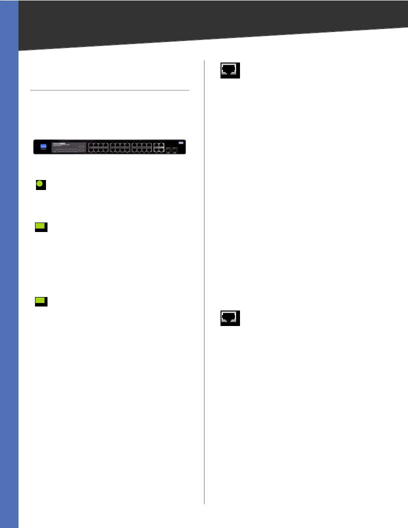
Front Panel
The LEDs and ports are located on the front panel of the Switch..
Front Panel
POWER (Green/Amber) Lights up green to indicate that power is being supplied to the Switch.. Lights amber to indicate that the Switch’s power-on-self-test (POST) is in progress.. Blinks amber to indicate that the POST has failed..
LINK/ACT (1-24) (Green/Amber) Lights up green to indicate a functional 10/100Mbps network link through the corresponding port with an attached device that does not use Power over Ethernet (PoE).. Lights up amber to indicate a functional 10/100Mbps network link through the corresponding port with an attached PoE device.. Blinks green to indicate that the Switch is actively sending or receiving data over that port..
LINK/ACT (G1-G4) (Green/Amber) Lights up green to indicate a functional 10/100Mbps network link through the corresponding port with an attached device.. Blinks green to indicate that the Switch is actively sending or receiving data over that port.. Lights amber to indicate a functional 1000Mbps network link.. Blinks green to indicate that the Switch is actively sending or receiving data over that port.. No amber light indicated that the link is at 10/100Mbps or there is no link..
Product Overview
ETHERNET 1-24 These RJ-45 ports support network speeds of either 10Mbps or 100Mbps, and can operate in half and full-duplex modes.. Auto-sensing technology enables each port to automatically detect the speed of the device connected to it (10Mbps or 100Mbps), and adjust its speed and duplex accordingly..
The Switch’s 10/100 RJ-45 ports also support the IEEE 802..3af Power-over-Ethernet (PoE) standard that enables DC power to be supplied to attached devicesusingwiresintheconnectingtwisted-pair cable.. Any 802..3af-compliant device attached to a port can directly draw power from the Switch over the twisted-pair cable without requiring its own separate power source.. This capability gives networkadministratorscentralizedpowercontrol for devices such as IP phones and wireless access points, which translates into greater network availability..
For each attached 802..3af-compliant device, the Switch automatically senses the load and dynamically supplies the required power.. The Switch delivers power to a device using the two data wire pairs in the twisted-pair cable.. Each port can provide up to 15..4W of power at the standard -48 VDC voltage..
To connect a device to a port, you will need to use Category 5 (or better) network cable..
ETHERNET G1-G4 The Switch is equipped with four Gigabit RJ-45 ports, two that are shared with two miniGBIC ports.. If a Gigabit miniGBIC port is being used, the associated RJ-45 port (G3 and/or G4) cannot be used..
All four ports support auto negotiation, so the optimum transmission mode (half or full duplex) and data rate (10, 100, or 1000 Mbps) can be selected automatically, if this feature is also supported by the attached device.. If a device connected to one of these ports does not support auto-negotiation, the communication mode of that port can be configured manually..
Each port also supports IEEE 802..3-2002 auto negotiation of flow control, so the Switch can automatically prevent port buffers from becoming saturated..
These ports support automatic MDI/MDI-X operation, so you can use straight-through cables for all network connections to PCs, servers, or additional switches..
24-Port 10/100 + 4-Port Gigabit Switch with WebView and Power over Ethernet |
|
Chapter 2
MiniGBIC (1-2) The Switch is equipped with two miniGBIC ports that have shared Gigabit Ethernet ports (G3 and G4) which provide for the installation of one expansion module.. These ports provide links to high-speed network segments or individual workstations at speeds of up to 1000Mbps (Gigabit Ethernet)..
To establish a Gigabit Ethernet connection using a miniGBIC port, you will need to install a MGBT1, MGBSX2, or MGBLH1 Gigabit expansion module and use Category 5e cabling or fiber optic cabling..
To establish a Fast Ethernet connection using a miniGBIC port, you will need to install a MFEFX1 (100BASE-FX) or MFELX1 (100BASE-LX) 100SFP Transceiver and use fiber optic cabling..
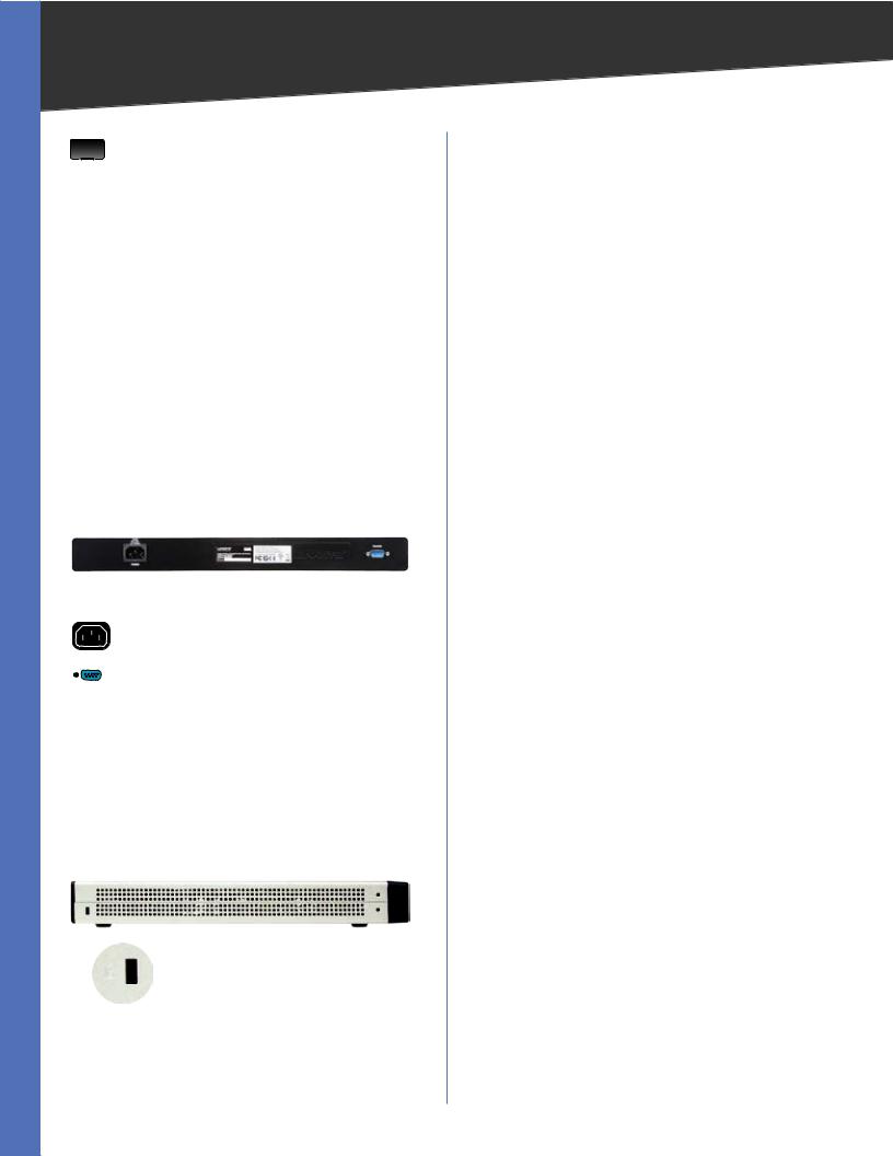
Back Panel
The console and power ports are located on the back panel of the Switch..
Back Panel
POWER The Power port is where you will connect the AC power..
CONSOLE The Switch is equipped with a serial port labeled Console (located on the back of the switch) that allows you to connect to a computer’s serial port (for configuration purposes) using the provided serial cable.. You can use HyperTerminal to manage the Switch using the console port..
Side Panel
The security slot is located on a side panel of the Switch..
Side Panel
SECURITY SLOT The security slot can be utilized to attach a lock to the Switch..
Product Overview
24-Port 10/100 + 4-Port Gigabit Switch with WebView and Power over Ethernet
Chapter 3
Chapter 3:
Connecting the Switch
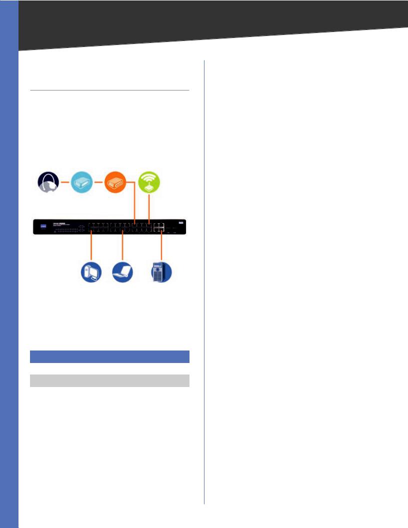
Overview
This chapter will explain how to connect network devices to the Switch.. The following diagram shows a typical network configuration..
|
Cable../DSL |
|
Wireless Access |
Internet |
Modem |
Router |
Point |
Desktop |
Notebook |
Server |
Typical Network Configuration
When you connect your network devices, make sure you don’t exceed the maximum cabling distances, which are listed in the following table:
Maximum Cabling Distances
From |
To |
Maximum Distance |
|
|
|
Switch |
Switch or Hub |
100 meters (328 feet) |
Hub† |
Hub |
5 meters (16..4 feet) |
Switch or Hub† |
Computer |
100 meters (328 feet) |
|
|
|
†A hub refers to any type of 100Mbps hub.. A 10Mbps hub connected to another 10Mbps hub can span up to 100 meters (328 feet)..
Pre-Installation Considerations
Fast Ethernet Considerations
If you are using the Switch for Fast Ethernet (100Mbps) applications, you must observe the following guidelines:
Connecting the Switch
Full-Duplex Considerations
The Switch provides full-duplex support for its RJ-45 ports.. Full-duplex operation allows data to be sent and received simultaneously, doubling a port’s potential data throughput.. If you will be using the Switch in full-duplex mode, the maximum cable length using Category 5 cable is 328 feet (100 meters)..
1000BASE-T Cable Requirements
All Category 5 UTP cables that are used for 100Base-TX connections should also work for 1000Base-T, providing that all four wire pairs are connected.. However, it is recommended that for all critical connections, or any new cable installations, Category 5e (enhanced Category 5) or Category 6 cable should be used.. The Category 5e specification includes test parameters that are only recommendations for Category 5.. Therefore, the first step in preparing existing Category 5 cabling for running 1000Base-T is a simple test of the cable installation to be sure that it complies with the IEEE 802..3ab standards..
Positioning the Switch
Before you choose a location for the Switch, observe the following guidelines:
•Make sure that the Switch is accessible and that the cables can be connected easily..
•Keep cabling away from sources of electrical noise, power lines, and fluorescent lighting fixtures..
•Position the Switch away from water and moisture sources..
•To ensure adequate air flow around the Switch, be sure to provide a minimum clearance of two inches (50mm)..
•Do not stack free-standing Switches more than four units high..
Placement Options
There are two ways to physically install the Switch, either set the Switch on its four rubber feet for desktop placement or mount the switch in a standard-sized, 19-inch high rack for rack-mount placement..
24-Port 10/100 + 4-Port Gigabit Switch with WebView and Power over Ethernet |
|
Chapter 3 |
Connecting the Switch |
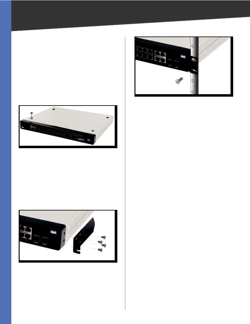
Desktop Placement
•Attach the rubber feet to the recessed areas on the bottom of the Switch..
•Place the Switch on a desktop near an AC power source..
•Keep enough ventilation space for the switch and check the environmental restrictions mentioned in “Appendix C: Specifications” as you are placing the Switch..
•Connect the Switch to network devices according to the Hardware Installation instructions below..
Attaching the Switch’s Rubber Feet
Rack-Mount Placement
To rack-mount the Switch in any standard 19-inch rack, follow the instructions described below..
1. Place the Switch on a hard flat surface with the front panel faced towards your front side..
2. Attach a rack–mount bracket to one side of the Switch with the supplied screws and secure the bracket tightly..
Attaching the Brackets
3. Follow the same steps to attach the other bracket to the opposite side..
4. After the brackets are attached to the Switch, use suitable screws to securely attach the brackets to any standard 19-inch rack..
Mounting in Rack
5. Connect the Switch to network devices according to the Hardware Installation instructions below..
Hardware Installation
To connect network devices to the Switch, follow these instructions:
1. Make sure all the devices you will connect to the Switch are powered off..
2. Connect a Category 5 Ethernet network cable to one of the numbered ports on the Switch..
3. Connect the other end to a PC or other network device..
4. Repeat steps 2 and 3 to connect additional devices.. If pre-standard or 802..3af-compliant PoE devices are connected to the Switch’s 10/100 ports, the Switch automatically supplies the required power..
5. If you are using a miniGBIC port, then connect a miniGBIC module to the miniGBIC port.. For detailed instructions, refer to the module’s documentation..
6. Connect the supplied power cord to the Switch’s power port, and plug the other end into an electrical outlet.. When connecting power, always use a surge protector..
7. Power on the devices connected to the Switch.. Each active port’s corresponding LED will light up on the Switch..
Uplinking the Switch
To uplink the Switch, connect one end of a Cat 5 (or better) Ethernet network cable into one of the 4 gigabit ports, and then connect the other end of the cable into the peripheral device’s uplink port.. MDI/MDIX will automatically detect the speed and cable type..
The hardware installation is complete.. Proceed to“Chapter 4: Configuration using the Console Interface”, for directions on how to set up the Switch..
24-Port 10/100 + 4-Port Gigabit Switch with WebView and Power over Ethernet |
|

Chapter 4
Chapter 4:
Configuration Using the
Console Interface
Overview
The Switch features a menu-driven console interface for basic switch configuration.. You can easily manage your network from the screens through the console port.. Before you can use the console interface, you will need to configure the HyperTerminal application..
Configuring the HyperTerminal Application
1. Click the Start button..
2. Select Programs > Accessories > Communications > HyperTerminal..
Start > Programs > Accessories > Communications > HyperTerminal
3. Enter a name for this connection.. In the example, the name of the connection is SRW224G4P.. Select an icon for the application, then click OK..
HyperTerminal Connection Description Screen
Configuration Using the Console Interface
4. Select a port to communicate with the switch.. Select
COM1 or COM2..
HyperTerminal Connect To Screen
5. Set the serial port settings as follows, then click OK.. Bits per Second: 38400
Databits: 8
Parity: None Stop bits: 1
Flow control: None
HyperTerminal Properties Screen
24-Port 10/100 + 4-Port Gigabit Switch with WebView and Power over Ethernet |
|
Chapter 4 |
Configuration Using the Console Interface |
Configuring the Switch through the Console Interface
The Console Interface consist of a series of menus.. Each menu has several options, which are listed vertically.. A highlight in each menu lets you select the option you wish to choose; pressing the Enter key activates the highlighted option..
To navigate through the Console Interface, use the Up Arrow or Down Arrow keys or use the Number keys to select the respective option (for example, press the 5 key to highlight Help).. The Enter key selects an option and the Esc key returns to the previous selection; menu options and any values entered or present are highlighted.. Note that the bottom of the window provides help, indicating the appropriate keys to use..
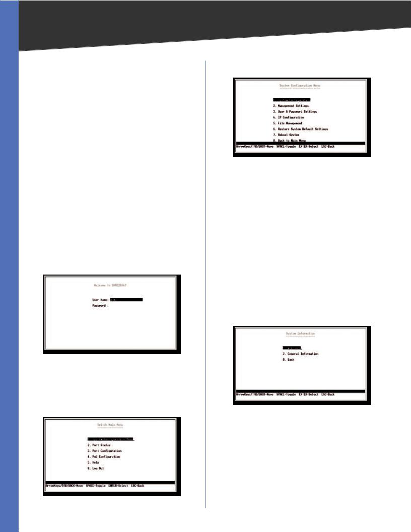
Login
When you finish configuring the HyperTerminal, the Login screen appears.. The first time you open the Console Interface, use the default username admin and leave the password blank and press the Enter key.. You can set a password later from the User and Password Settings screen..
Console Login Screen
Switch Main Menu
The Main Menu screen displays six menu choices: System Configuration Menu, Port Status, Port Configuration, PoE Configuration, Help, and Log Out..
Main Menu
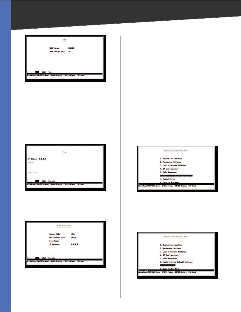
System Configuration Menu
System Configuration Menu
System Configuration Menu options: 1. System Configuration
2. Management Settings
3. User and Password Settings
4. IP Configuration
5. File Management
6. Restore System Default Settings
7. Reboot System
0. Back to Main Menu..
System Configuration
From the System Information screen you can check current firmware versions and other general switch information..
System Information
24-Port 10/100 + 4-Port Gigabit Switch with WebView and Power over Ethernet
Chapter 4 |
Configuration Using the Console Interface |
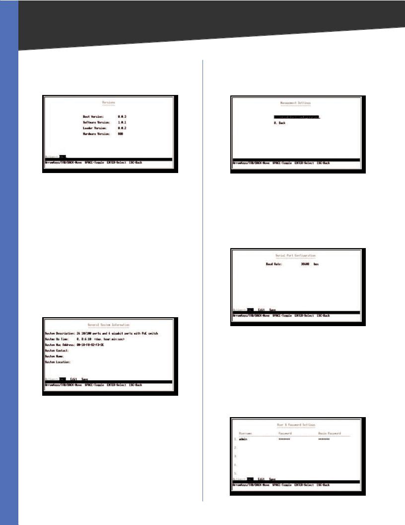
Versions
The Versions screen displays the Boot Version, Software Version, Loader Version and the Hardware Version..
Versions
Boot Version This file runs when the Switch is turned on.. It performs power-on diagnostics and loads the operating system for the Switch..
Software Version This file contains the programming code that runs the Switch..
Loader Version This file loads the software from storage memory to main memory..
Hardware Version The current hardware setup of the Switch..
General Information
The General Information screen displays the System Description, System Up Time, System Mac Address, System Contact, System Name and System Location..
General Information
Management Settings
The Management Settings screen displays the Serial Port Configuration..
Management Settings
Serial Port Configuration
The Serial Port Configuration screen displays the current setting for the baud rate.. The baud rate can be changed by selecting Edit then using the spacebar to toggle through the different baud rates.. Use the Save action to set the new baud rate..
Serial Port Configuration
User & Password Settings
The User & Password Settings screen displays user account information on the Switch.. The default account is the admin account.. To add a new user, use the arrow keys to select Edit and then press the Enter key, then enter the user name of the new account and assign a password to the account.. The password must be re-entered into the Again Password column to confirm the password..
User & Password Settings
24-Port 10/100 + 4-Port Gigabit Switch with WebView and Power over Ethernet |
|
Chapter 4 |
Configuration Using the Console Interface |
You can add up to five user accounts in addition to the default admin account.. The admin account cannot be deleted from the system..
To save the new user account information, use the arrow keys to select Save and press Enter..
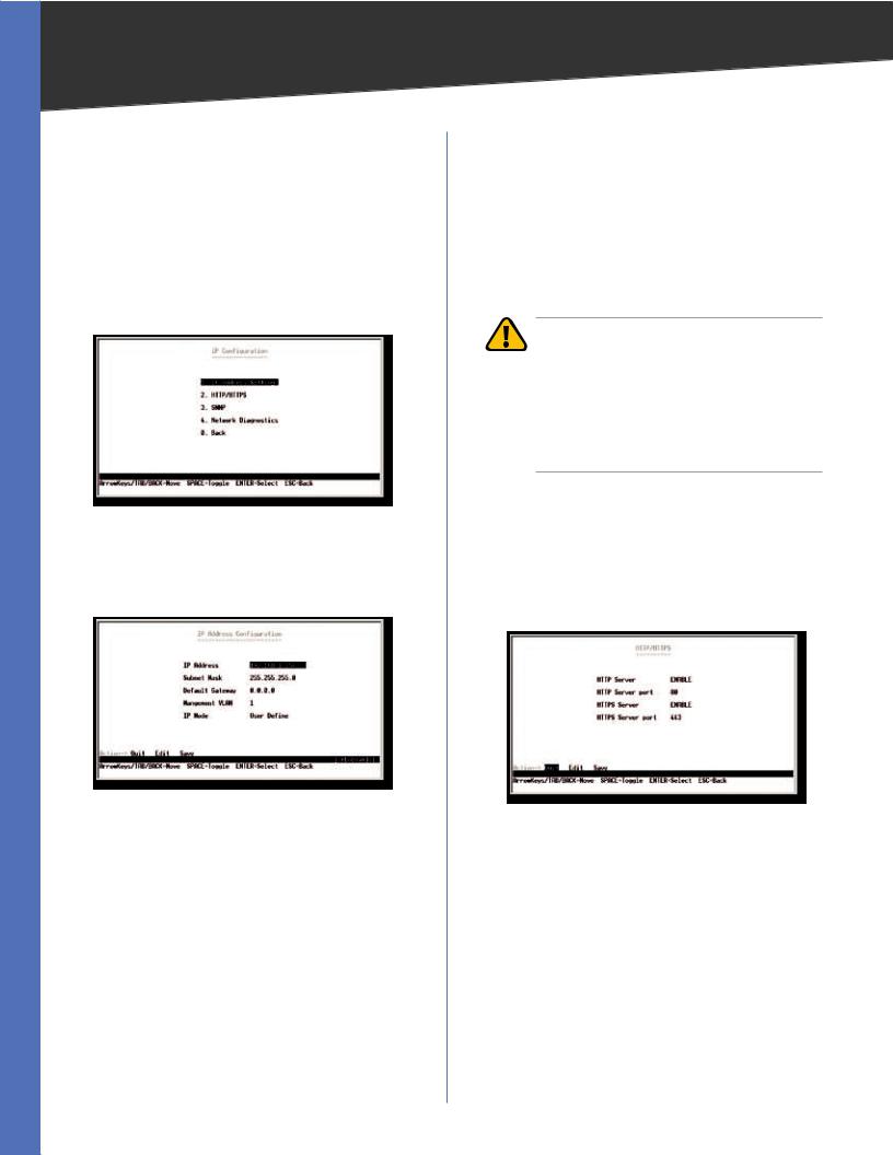
IP Configuration
The IP Configuration screen displays four menu choices: IP Address Settings, HTTP/HTTPS, SNMP, and Network Diagnostics..
IP Configuration
IP Address Settings
The IP Address Settings screen allows you to set the IP information for the Switch..
IP Address Configuration
IP Address This sets the Switch’s IP Address.. The default setting is 192..168..1..5..
Subnet Mask This combined with the IP Address defines the Switch’s network address..
Default Gateway This defines the IP Address for the default gateway of the network..
Management VLAN Set the ID number of the Management VLAN.. This is the only VLAN through which you can gain management access to the Switch.. By default, all ports on the Switch are members of VLAN 1, so a management station can be connected to any port on the Switch.. However, if other VLANs are configured and you change the Management VLAN, you may lose management access to the Switch.. In this case, you should reconnect the management station to a port that is a member of the Management VLAN..
WARNING: Do not define the Management VLAN as a VLAN that has yet to be created.. If the VLAN does not exist already, the software will automatically create the VLAN but will not assign VLAN membership.. If this happens, the Switch cannot be managed via the web based utility until it has been reconfigured via the console interface..
IP Mode Choose to have either a user-defined IP address or to have it assigned by DHCP or BOOTP..
HTTP/HTTPS
The HTTP/HTTPS screen allows you to set the Hyper Text Transfer Protocol server (web server) information for the Switch..
HTTP/HTTPS
HTTP Server Enable or disable the Switch’s HTTP server function..
HTTP Server port Set the TCP port that HTTP packets are sent and received from..
HTTPS Server Enable or disable the Secure HTTP server function of the Switch..
HTTPS Server port Set the TCP port that the HTTPS packets are sent and received from..
SNMP
The SNMP screen allows you to set the Switch’s SNMP settings..
24-Port 10/100 + 4-Port Gigabit Switch with WebView and Power over Ethernet |
10 |
Chapter 4 |
Configuration Using the Console Interface |
SNMP
SNMP Server Enable or Disable the SNMP function for the Switch..
SNMP Server Port Set the TCP port that will be used for sending and receiving SNMP packets..
Network Diagnostics
The Network Configuration screen allows you to use PING to test network connectivity.. Enter the IP address of the interface or device you wish to PING and select the Execute action..
Ping
File Management
The File Management screen allows you to upload and download files to the Switch using TFTP..
File Management
Source File Specify the location of the file to transfer.. Select one of the following:
•TFTP If the file is located on a TFTP server..
•Image If the file is a software code file..
• Startup-config If the file is a configuration file..
DestinationFile Specify where the file is to be transferred.. Select one of the following:
•TFTP If the file is to be uploaded to a TFTP server..
•Image If the file is to be downloaded as a software code file..
•Startup-config If the file is a configuration file
•Boot If the file is a boot file..
File Name Enter the name of the file to be uploaded or downloaded..
IP Address Enter the IP address of the TFTP server that will transfer the file..
Restore System Default Settings
To restore the Switch back to the factory default settings, select Restore System Default Setting and press Enter.. A confirmation message appears asking Are you sure? [Y/ N].. Press the Y key to continue or the N key to cancel the action..
Restore Default
Reboot System
If you want to restart the Switch, select Reboot System and press Enter.. A confirmation message appears asking Reboot Now? [Y/N].. Press the Y key to continue or the N key to cancel the action..
Reboot System
24-Port 10/100 + 4-Port Gigabit Switch with WebView and Power over Ethernet |
11 |
Chapter 4 |
Configuration Using the Console Interface |
Back to Main Menu
Select Back to Main Menu if you want to return to the main menu..
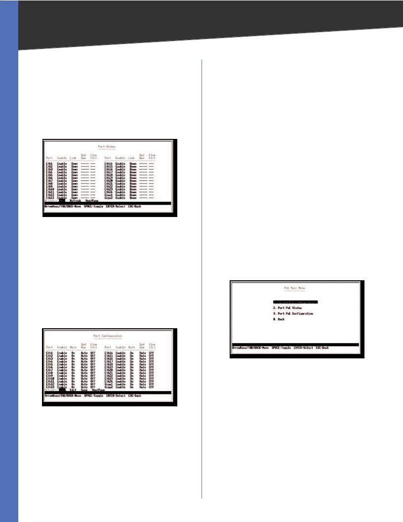
Port Status
The Port Status screen allows you to view the status of a port.. The Port, Enable, Link Status, Spd/Dpx, and Flow Control are displayed..
Port Status
Ports 1 through 24 are Ethernet RJ-45 ports and are all 10/100 ports.. Ports G3 and G4 are shared with the miniGBIC ports.. If there is a connection to one of the miniGBIC ports then the corresponding Gigabit RJ-45 port cannot be used..
Port Configuration
You can use the Port Configuration screen to enable/ disable an interface, set auto-negotiation and the interface capabilities to advertise, or manually fix the speed, duplex mode, and flow control..
Port Configuration
Enable Allows you to manually enable or disable an interface.. You can disable an interface due to abnormal behavior (for example, excessive collisions), and then enable it again, once the problem has been resolved.. You may also disable an interface for security reasons..
Auto-negotiation (Port Capabilities) This option enables or disables auto-negotiation.. When auto-negotiation is enabled, you need to specify the capabilities to be advertised.. When auto-negotiation is disabled, you can force the settings for speed, mode, and flow control.. The following capabilities are supported..
•10half Supports 10 Mbps half-duplex operation
•10full Supports 10 Mbps full-duplex operation
•100half Supports 100 Mbps half-duplex operation
•100full Supports 100 Mbps full-duplex operation
•1000full Supports 1000 Mbps full-duplex operation
Default: Auto-negotiation enabled; Advertised capabilities for 100Base-TX – 10half, 10full, 100half, 100full; 1000Base- T – 10half, 10full, 100half, 100full, 1000full; 1000Base-SX/ LX/LH (SFP) – 1000full; 100Base-FX (SFP) – 100full
Speed/Duplex Allowsmanualselectionofportspeedand duplex mode (that is, with auto-negotiation disabled)..
Flow Control Allows automatic or manual selection of flow control..
PoE Configuration
The PoE Main Menu screen displays three menu choices and a back option:
PoE Main Menu
1. System PoE Configuration
2. Port PoE Status
3. Port PoE Configuration
24-Port 10/100 + 4-Port Gigabit Switch with WebView and Power over Ethernet |
12 |
Chapter 4 |
Configuration Using the Console Interface |
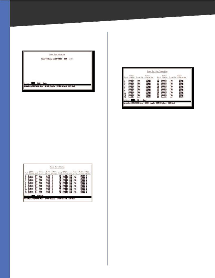
System PoE Configuration
The Power Configuration screen allows you to set the PoE power allocation from the Switch to connected devices..
System PoE Configuration
The Switch’s power management enables total Switch power and individual port power to be controlled within a configuredpowerbudget..Portpowercanbeautomatically turned on and off for connected devices, and a per-port power priority can be set so that the Switch never exceeds its allocated power budget.. When a device is connected to a port, its power requirements are detected by the Switch before power is supplied.. If the power required by a device exceeds the power budget of the port or the whole Switch, power is not supplied..
Port PoE Status
The Power Port Status screen allows you to view the current PoE settings for each port on the Switch..
Power Port Status
Ports can be set to one of three power priority levels: critical, high, or low.. To control the power supply within the Switch’s budget, ports set at critical or high priority have power enabled in preference to those ports set at low priority.. For example, when a device is connected to a port set to critical priority, the Switch supplies the required power, if necessary by dropping power to ports set for a lower priority.. If power is dropped to some low-priority ports and later the power demands on the Switch fall back within its budget, the dropped power is automatically restored..
Port PoE Configuration
The Power Port Configuration screen allows you to set the PoE settings for each port.. Select the Edit action and use the left-right and up-down arrows to select the attribute you would like to set.. You can set the Admin Status, the Priority, and the Power Allocation.. Use the Save action to save the new settings..
Power Port Configuration
Logout
Select Logout to log out of the Console Configuration Utility..
24-Port 10/100 + 4-Port Gigabit Switch with WebView and Power over Ethernet |
13 |
Chapter 5
Chapter 5:
Configuring the Switch
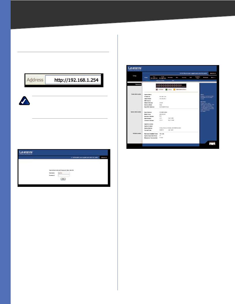
Open your web browser and enter http://192.168.1.254 into the address field.. Press the Enter key and the Password screen will appear..
Address Bar
NOTE: The default IP address is 192.168.1.254.. If the IP address has been changed using DHCP or via the console interface, enter the assigned IP address instead of the default..
The first time you open the web based utility, enter admin (the default username) in the username field and leave the password blank.. Click the OK button.. You can set a password later from the Admin tab’s User Accounts screen..
Login Screen
Setup
The first screen displays the Summary screen on the Setup tab.. There are 10 tabs across the top of the screen: Setup,
Port management, VLAN Management, Statistics, ACL, Security, QoS, Spanning Tree, Multicast, and a More tab.. Click the More tab to access the SNMP, Admin and Logout tabs.. Each tab contains screens that will help you configure and manage the Switch..
Configuring the Switch
Setup > Summary
The Setup > Summary screen displays a summary of Switch information.. The settings cannot be modified from the Setup > Summary screen.. Many of the settings can be modified from the Setup > Network Settings screen..
Setup > Summary
Device Information
System Name Displays the name for the Switch, if one has been entered..
IP Address The IP address assigned to the Switch is displayed.. (The default IP address is 192.168.1.254)
Subnet Mask The Subnet Mask assigned to the Switch is displayed (The default is 255.255.255.0)..
DNS Servers The IP address of your ISP’s server, which translates the names of websites into IP addresses..
Default Gateway IP address of the gateway router between this device and management stations that exist on other network segments.. (Default: 0.0.0.0)
Address Mode Specifies whether IP functionality is enabled via manual configuration (Static), Dynamic Host Configuration Protocol (DHCP), or Boot Protocol (BOOTP).. If DHCP/BOOTP is enabled, IP will not function until a reply has been received from the server.. Requests will be broadcast periodically by the Switch for an IP address.. (DHCP/BOOTP values can include the IP address, subnet mask, and default gateway..)
Base MAC Address The MAC address of the Switch is displayed..
24-Port 10/100 + 4-Port Gigabit Switch with WebView and Power over Ethernet |
14 |
Chapter 5 |
Configuring the Switch |
System Information
Serial Number The serial number of the Switch is displayed..
Model Name The model name of the Switch is displayed..
Hardware version The current hardware version is displayed..
Boot Version The current boot version is displayed..
Firmware Version The current software version is displayed..
System Location Displays the location of the system if it has been defined..
System Contact The name of the administrator will appear here if it has been defined..
System Uptime Length of time the management agent has been up..
Current Time Displays the current time..
PoE Information
Maximum Available Power Displays the maximum power that can be supplied to a connected PoE device..
System Operation Status Displays the operational status of the Power over Ethernet mechanism..
Mainpower Consumption Displays the current number of watts that the Switch is providing to PoE devices..
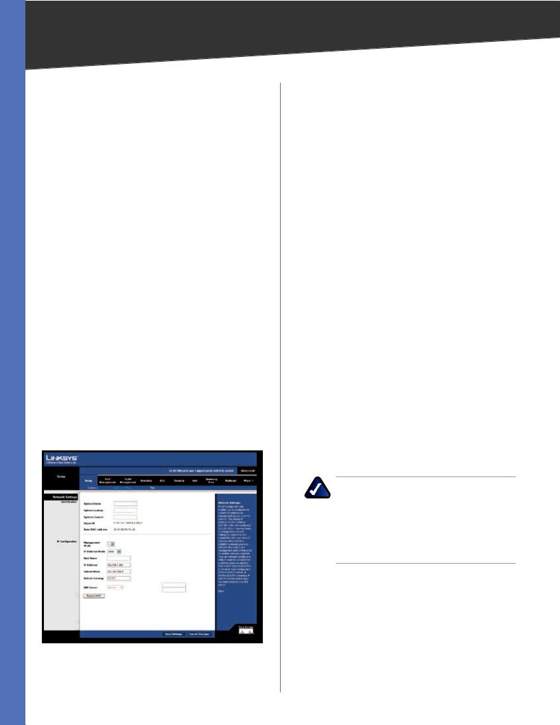
Setup > Network Settings
Setup > Network Settings
The Network Settings screen allows you to edit the following information..
Identification
System Name Specifies the name of the Switch.. Enter the name into the text field provided.. By default, a system name is not defined..
System Location This field is used for entering a description of where the Switch is located, such as 3rd floor..
System Contact Enter the name of the administrator responsible for the system..
Object ID The system object identifier is displayed here..
Base MAC Address Physical address of a device mapped to this interface..
IP Configuration
To manually configure IP settings, you need to set an IP address and subnet mask compatible with your network.. You may also need to establish a default gateway between the Switch and management stations that exist on another network segment..
An IP address may be used for management access to the Switch over your network.. You may also need to establish a default gateway between the Switch and management stations that exist on another network segment..
Management VLAN ID of the configured VLAN (1-4094, no leading zeroes).. By default, all ports on the Switch are members of VLAN 1.. However, the management station can be attached to a port belonging to any VLAN, as long as that VLAN has been assigned an IP address..
IP Address Mode Specifies whether IP functionality is enabled via manual configuration (Static), Dynamic Host Configuration Protocol (DHCP), or Boot Protocol (BOOTP)..
NOTE: If DHCP/BOOTP is enabled, IP will not function until a reply has been received from the server.. Requests will be broadcast periodically by the Switch for an IP address.. If the mode is set to DHCP/BOOTP and a server is not available, you can reconfigure the settings by connecting the console interface directly to a computer..
Select the IP Address Mode using the drop-down menu. Selecting Static will allow you to enter a static IP address, subnet mask and default gateway using the text field provided.. Selecting BOOTP or DHCP disables these text boxes and auto assigns an IP address.. The default setting is Static..
Host Name Assign a host name to the Switch..
24-Port 10/100 + 4-Port Gigabit Switch with WebView and Power over Ethernet |
15 |
Chapter 5 |
Configuring the Switch |
IP Address Address of the VLAN interface that is allowed management access.. Valid IP addresses consist of four numbers, 0 to 255, separated by periods.. (Default:
192.168.1.254)
Subnet Mask This mask identifies the host address bits used for routing to specific subnets.. (Default:
255.255.255.0)
Default Gateway IP address of the gateway router between this device and management stations that exist on other network segments.. (Default: 0.0.0.0)
DNS Server Enter the IP address of the DNS server into the text field.. A second DNS address can be specified in the additional text field provided..
Click Save Settings to save the changes..
Click Restart DHCP to assign a new IP address using DHCP..
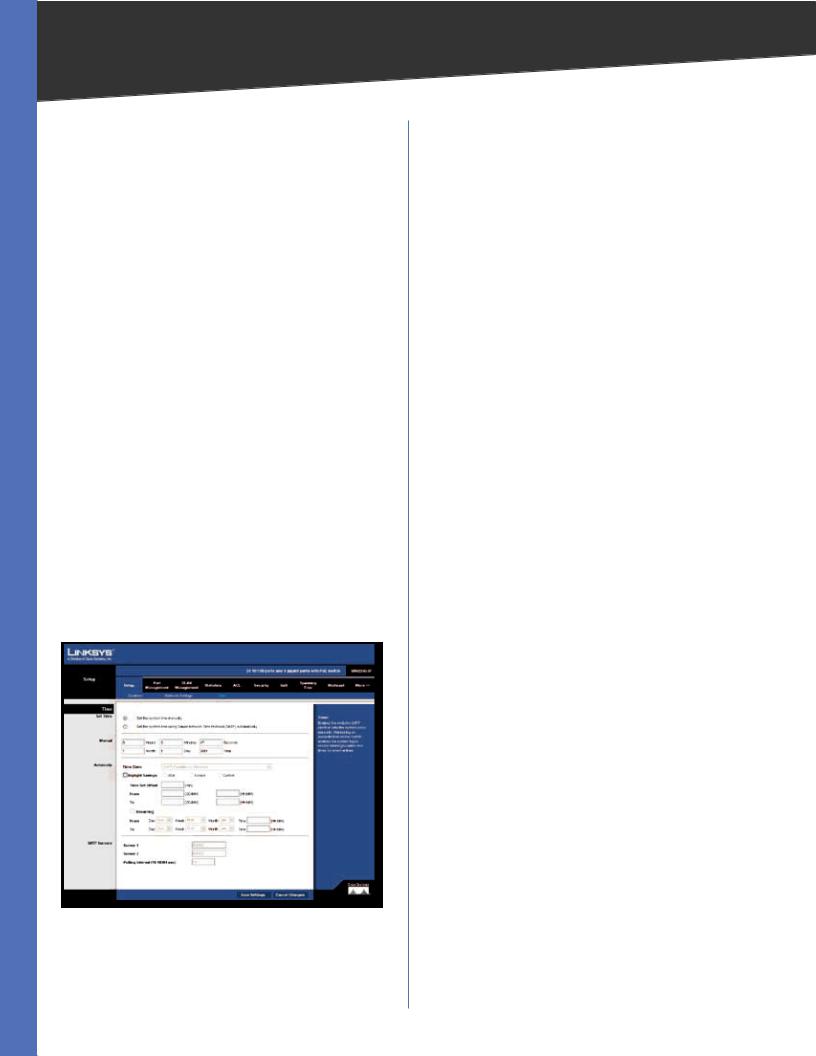
Setup > Time
Simple Network Time Protocol (SNTP) allows the Switch to set its internal clock based on periodic updates from a time server (SNTP or NTP).. Maintaining accurate time on the Switch enables the system log to record meaningful dates and times for event entries.. If the clock is not set, the Switch will only record the time from the factory default set at the last bootup.. When the SNTP client is enabled, the Switch periodically sends a request for a time update to a configured time server.. You can configure up to two time server IP addresses.. The Switch will attempt to poll each server in the sequence..
Setup > Time
Set Time
Set the system time manually This option allows you to set the time and date manually for the Switch..
Set the system time using Simple Network Time Protocol (SNTP) automatically Sets the system clock automatically using SNTP..
Manual
Hours The hour is entered here..
Minutes The minutes is entered here..
Seconds The seconds is entered here..
Month The month is entered here..
Day The day is entered here..
Year The year is entered here..
Automatic
Sets the system clock automatically using SNTP..
Time Zone Set the time zone by selecting it from the drop-down menu..
Daylight Savings Enable daylight saving time by checking the checkbox.. Then set USA, Europe, or custom daylight saving time by clicking the appropriate option..
Time Set Offset Custom daylight saving time is set by entering the time difference in minutes into the Time Set Offset field.. Set the date for this offset by entering the day and month (DD/MM) in the From and To fields..
Recurring To enable a recurring custom daylight savings time, check the Recurring checkbox.. Set the day, week, and month the time difference will be recurring (From and To) by using the drop-down menus.. Set the time (From and To) of the recurrence using the field provided (HH:MM)..
SNTP Servers
Sets the IP address of up to two SNTP servers.. Server 1 Set the IP address of the SNTP server..
Server 2 Set the IP address of an additional SNTP server..
Polling Internal (16-16384 sec) The value entered here determines the number of seconds between each time the Switch contacts the SNTP server for an update..
24-Port 10/100 + 4-Port Gigabit Switch with WebView and Power over Ethernet |
16 |
Chapter 5 |
Configuring the Switch |
Port Management
Port functionality can be controlled using the Port Management settings.. Speeds, duplex, grouping, and Power over Ethernet settings, and more can be defined..
Port Management > Port Settings
You can manually configure the speed, duplex mode, and flow control used on specific ports, or use to detect the connection settings used by the attached device.. Use the full-duplex mode on ports whenever possible to double the throughput of switch connections.. Flow control should also be enabled to control network traffic during periods of congestion and prevent the loss of packets when port buffer thresholds are exceeded.. The Switch supports flow control based on the IEEE 802..3x standard..
This screen displays the current connection status, including the description, administrative status, link status, speed, duplex mode, MDI/MDIX, flow control, type, and LAG..
Port Management > Port Settings
Port Displays the port number..
Description Displays a description for the port, if one has been defined..
Administrative Status Displays the administrative status of the appropriate port..
Link Status Displays the link status of the port.. Speed Displays the current speed of the port.. Duplex Displays the current duplex mode of the port..
MDI/MDIX Indicates if the port is being utilized as an MDI or MDIX port..
Flow Control Indicates the type of flow control currently in use (IEEE 802..3x, Back-Pressure, or None)..
Type Indicates the port type (100Base-TX, 1000Base-T, or SFP)..
LAG Indicates whether the port is a LAG member..
Each port has a Detail button that opens a screen for editing port settings.. Click the Detail button to open the Port Setting detail screen for the desired port..
Edit Port Settings
You can use the Port Setting detail screen to enable/disable an interface, set and interface capability advertisements, or manually force the speed, duplex mode, and flow control..
Port Management > Edit Port Settings
This screen allows you to edit the following information for each port on the Switch..
Port Use the port drop-down menu to select a port..
Port Configuration
Description Use this field to describe the interface.. (Range: 1-64 characters)
Speed Duplex Used to manually set the port speed and duplex mode when autonegotiation is disabled..
Autonegotiation Enables or disables autonegotiation.. When autonegotiation is enabled, you need to specify the capabilities to be advertised.. When autonegotiation is disabled, you can force the settings for speed, mode, and flow control.. Autonegotiation is enabled by default..
24-Port 10/100 + 4-Port Gigabit Switch with WebView and Power over Ethernet |
17 |
Chapter 5 |
Configuring the Switch |
The following capabilities are supported..
•10half Supports 10 Mbps half-duplex operation
•10full Supports 10 Mbps full-duplex operation
•100half Supports 100 Mbps half-duplex operation
•100full Supports 100 Mbps full-duplex operation
•1000half Supports 1000 Mbps half-duplex operation
•1000full Supports 1000 Mbps full-duplex operation
•Sym (Gigabit only) Check this item to transmit and receive pause frames, or clear it to autonegotiate the sender and receiver for asymmetric pause frames..
Flow Control Allows automatic or manual selection of flow control..
Port Broadcast Control
Status To enable broadcast control on a specified port, mark the Enabled checkbox for that port..
Threshold You can protect your network from broadcast storms by setting a threshold for broadcast traffic for all ports.. Any broadcast packets exceeding the specified threshold will then be dropped..
After you modify the required port settings, click Apply..
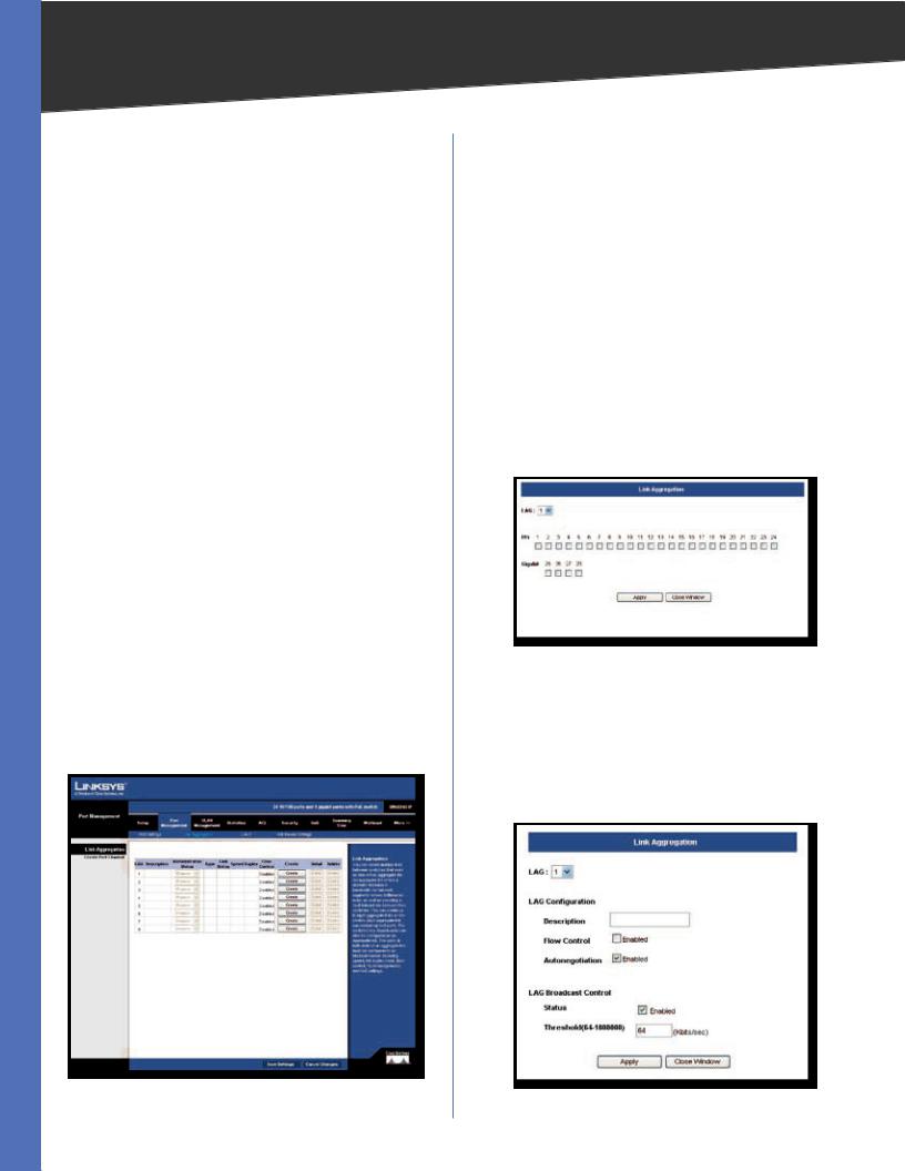
Port Management > Link Aggregation
You can create multiple links between devices that work as one virtual, aggregate link (LAG).. An aggregated link offers a dramatic increase in bandwidth for network segments where bottlenecks exist, as well as providing a fault-tolerant link between two devices.. You can create up to four LAGs on the Switch.. Each LAG can contain up to eight ports..
Port Management > Link Aggregation
LAG Displays the LAG number..
Description Displays the description assigned to the interface..
Administrative Status Indicates whether the interface is enabled or disabled..
Type Indicates if a LAG has been manually configured (static) or dynamically set through LACP..
Link Status Displays the status of the link.. Speed Displays the port speed..
Duplex Displays the duplex mode.. Flow Control Displays the flow control..
Create To create a new LAG, click the Create button in the Create column, then add members to the LAG by clicking on the Select Member button.. The select member screen for the Link Aggregation opens..
Port Management > Link Aggregation > Select Member
The LAG number is shown in the LAG drop-down menu.. The Ethernet ports are represented by check boxes.. Assign up to 8 ports to the LAG by checking the check boxes of the ports, then click Apply..
Detail To configure the LAG and the LAG broadcast control, click the Detail button.. The Link Aggregation detail screen will be displayed..
Port Management > Link Aggregation > Detail
24-Port 10/100 + 4-Port Gigabit Switch with WebView and Power over Ethernet |
18 |
Loading...