


 Loading...
2.4GHz Wireless-N |
User Guide |
Broadband Router |
|
WIRELESS |
|
Model No. WRT300N |
|

Wireless-N Broadband Router
Copyright and Trademarks
Specifications are subject to change without notice. Linksys is a registered trademark or trademark of Cisco Systems, Inc. and/or its affiliates in the U.S. and certain other countries. Copyright © 2006 Cisco Systems, Inc. All rights reserved. Other brands and product names are trademarks or registered trademarks of their respective holders.
WARNING: This product contains chemicals, including lead, known to the State of California to cause cancer, and birth defects or other reproductive harm. Wash hands after handling.
How to Use This User Guide
This User Guide has been designed to make understanding networking with the Wireless-N Broadband Router easier than ever. Look for the following items when reading this User Guide:
This checkmark means there is a note of interest and is something you should pay special attention to while using the Wireless-N Broadband Router.
This exclamation point means there is a caution or warning and is something that could damage your property or the Wireless-N Broadband Router.
This question mark provides you with a reminder about something you might need to do while using the Wireless-N Broadband Router.
In addition to these symbols, there are definitions for technical terms that are presented like this:
word: definition.
Also, each figure (diagram, screenshot, or other image) is provided with a figure number and description, like this:
Figure 0-1: Sample Figure Description
Figure numbers and descriptions can also be found in the “List of Figures” section in the “Table of Contents”.
WRT300N-UG-60324NC JL
Wireless-N Broadband Router
Table of Contents
Chapter 1: Introduction |
1 |
Welcome |
1 |
What’s in this User Guide? |
2 |
Chapter 2: Planning Your Wireless Network |
4 |
Network Topology |
4 |
Ad-Hoc versus Infrastructure Mode |
4 |
Network Layout |
4 |
Chapter 3: Getting to Know the Wireless-N Broadband Router |
6 |
The Back Panel |
6 |
The Front Panel |
7 |
The Top Panel |
7 |
Chapter 4: Connecting the Wireless-N Broadband Router |
8 |
Hardware Installation |
8 |
Chapter 5: Configuring the Wireless-N Broadband Router |
9 |
Overview |
9 |
How to Access the Web-based Utility |
11 |
The Setup Tab - Basic Setup |
11 |
The Setup Tab - DDNS |
17 |
The Setup Tab - MAC Address Clone |
19 |
The Setup Tab - Advanced Routing |
20 |
The Wireless Tab - Basic Wireless Settings |
22 |
The Wireless Tab - Wireless Security |
23 |
The Wireless Tab - Wireless MAC Filter |
26 |
The Wireless Tab - Advanced Wireless Settings |
27 |
The Security Tab - Firewall |
29 |
The Security Tab - VPN Passthrough |
30 |
The Access Restrictions Tab - Internet Access Policy |
31 |
The Applications & Gaming Tab - Single Port Forwarding |
33 |
The Applications & Gaming Tab - Port Range Forwarding |
34 |
The Applications & Gaming Tab - Port Range Triggering |
35 |
The Applications & Gaming Tab - DMZ |
36 |
The Applications and Gaming Tab - QoS |
37 |
Wireless-N Broadband Router |
|
The Administration Tab - Management |
40 |
The Administration Tab - Log |
42 |
The Administration Tab - Diagnostics |
43 |
The Administration Tab - Factory Defaults |
44 |
The Administration Tab - Firmware Upgrade |
45 |
The Status Tab - Router |
46 |
The Status Tab - Local Network |
47 |
The Status Tab - Wireless |
48 |
Appendix A: Troubleshooting |
49 |
Common Problems and Solutions |
49 |
Frequently Asked Questions |
57 |
Appendix B: Wireless Security |
63 |
Security Precautions |
63 |
Security Threats Facing Wireless Networks |
63 |
Appendix C: Upgrading Firmware |
66 |
Appendix D: Windows Help |
67 |
Appendix E: Finding the MAC Address and IP Address for Your |
|
Ethernet Adapter |
68 |
Windows 98SE or Me Instructions |
68 |
Windows 2000 or XP Instructions |
69 |
For the Router’s Web-based Utility |
69 |
Appendix F: Glossary |
70 |
Appendix G: Specifications |
75 |
Appendix H: Warranty Information |
77 |
Appendix I: Regulatory Information |
78 |
Appendix J: Contact Information |
84 |
Wireless-N Broadband Router
List of Figures
Figure 3-1: The Router’s Back Panel |
6 |
Figure 3-2: The Router’s Front Panel |
7 |
Figure 3-3: The Router’s Top Panel |
7 |
Figure 4-1: Connect the Modem |
8 |
Figure 4-2: Connect a PC |
8 |
Figure 4-3: Connect the Power |
8 |
Figure 5-1: Router Login |
11 |
Figure 5-2: Setup Tab - Basic Setup (Automatic Configuration - DHCP) |
11 |
Figure 5-3: Static IP |
12 |
Figure 5-4: PPPoE |
12 |
Figure 5-5: PPTP |
13 |
Figure 5-6: Telstra Cable |
13 |
Figure 5-7: L2TP |
14 |
Figure 5-8: DHCP Reservation |
16 |
Figure 5-9: Setup Tab - DDNS (DynDNS.org) |
17 |
Figure 5-10: Setup Tab - DDNS (TZO.com) |
18 |
Figure 5-11: Setup Tab - MAC Clone |
19 |
Figure 5-12: Setup Tab - Advanced Routing |
20 |
Figure 5-13: Routing Table |
21 |
Figure 5-14: Wireless Tab - Basic Wireless Settings |
22 |
Figure 5-15: Wireless Tab - Wireless Security (PSK-Personal) |
23 |
Figure 5-16: Wireless Security - PSK2-Personal |
23 |
Figure 5-17: Wireless Security - PSK-Enterprise |
24 |
Figure 5-18: Wireless Security - PSK2-Enterprise |
24 |
Figure 5-19: Wireless Security - RADIUS |
25 |
Figure 5-20: Wireless Security - WEP |
25 |
Figure 5-21: Wireless Tab - Wireless MAC Filter |
26 |
Figure 5-22: Wireless Client List |
26 |
Figure 5-23: Wireless Tab - Advanced Wireless Settings |
27 |
Figure 5-24: Security Tab - Firewall |
29 |
Figure 5-25: VPN Passthrough |
30 |
Wireless-N Broadband Router |
|
Figure 5-26: Access Restrictions Tab - Internet Access Policy |
31 |
Figure 5-27: Summary |
31 |
Figure 5-28: List of PCs |
32 |
Figure 5-29: Applications & Gaming Tab - Single Port Forwarding |
33 |
Figure 5-30: Applications & Gaming Tab - Port Range Forwarding |
34 |
Figure 5-31: Applications & Gaming Tab - Port Range Triggering |
35 |
Figure 5-32: Applications & Gaming Tab - DMZ |
36 |
Figure 5-33: DHCP Client Table |
36 |
Figure 5-34: Applications & Gaming Tab - QoS (Applications) |
37 |
Figure 5-35: QoS - Applications (Add a New Application) |
38 |
Figure 5-36: QoS - Online Games |
38 |
Figure 5-37: QoS - MAC Address |
38 |
Figure 5-38: QoS - MAC Address |
38 |
Figure 5-39: QoS - Voice Device |
39 |
Figure 5-40: Administration Tab - Management |
40 |
Figure 5-41: Administration Tab - Log |
42 |
Figure 5-42: View Log |
42 |
Figure 5-43: Administration Tab - Diagnostics |
43 |
Figure 5-44: Ping Test |
43 |
Figure 5-45: Traceroute Test |
43 |
Figure 5-46: Administration Tab - Factory Defaults |
44 |
Figure 5-47: Administration Tab - Firmware Upgrade |
45 |
Figure 5-48: Status Tab - Router |
46 |
Figure 5-49: Status Tab - Local Network |
47 |
Figure 5-50: Status Tab - Local Network |
47 |
Figure 5-51: Status Tab - Wireless |
48 |
Figure C-1: Firmware Upgrade |
66 |
Figure E-1: IP Configuration Screen |
68 |
Figure E-2: MAC Address/Adapter Address |
68 |
Figure E-3: MAC Address/Physical Address |
68 |
Figure E-4: Wireless MAC Filter |
69 |
Figure E-5: MAC Address Cloning |
69 |
Wireless-N Broadband Router
Chapter 1: Introduction
Welcome
Thank you for choosing the Linksys Wireless-N Broadband Router. The Wireless-N Broadband Router will allow you to network wirelessly better than ever, sharing Internet access, files and fun, easily and securely and with a greater range of up to three times farther than standard Wireless-G.
How does the Wireless-N Broadband Router do all of this? A router is a device that allows access to an Internet connection over a network. With the Wireless-N Broadband Router, this access can be shared over the four switched ports or via the wireless broadcast.
Use wireless security to secure your wireless network while the whole network is protected through a Stateful Packet Inspection (SPI) firewall and Network Address Translation (NAT) technology. The Router also offers VPN passthrough and other features, which can be configured through the easy-to-use, browser-based utility.
The incredible speed of Wireless-N makes it ideal for media-centric applications like streaming video and Voice over IP (VoIP) telephony, so your network can handle multiple data streams at the same time, with no degradation in performance.
But what does all of this mean?
Networks are useful tools for sharing computer resources. You can access one printer from different computers and access data located on another computer's hard drive. Networks are even used for playing multiplayer video games. So, networks are not only useful in homes and offices, they can also be fun.
PCs on a wired network create a LAN, or Local Area Network. They are connected with Ethernet cables, which is why the network is called “wired”.
PCs equipped with wireless cards or adapters can communicate without cumbersome cables. By sharing the same wireless settings, within their transmission radius, they form a wireless network. This is sometimes called a WLAN, or Wireless Local Area Network. The Wireless-N Broadband Router bridges wireless and wired networks, allowing them to communicate with each other.
Linksys recommends using the Setup Wizard on the Setup CD-ROM for first-time installation of the Router. If you do not wish to run the Setup Wizard, then use the instructions in this Guide to help you connect the Router and configure it. These instructions should be all you need to get the most out of the Wireless-N Broadband Router.
spi (stateful packet inspection) firewall: a technology that inspects incoming packets of information before allowing them to enter the network.
firewall: Security measures that protect the resources of a local network from intruders.
nat (network address translation): NAT technology translates IP addresses of a local area network to a different IP address for the Internet.
lan (local area network): The computers and networking products that make up the network in your home or office.
Chapter 1: Introduction |
1 |
Welcome
Wireless-N Broadband Router
What’s in this User Guide?
This user guide covers the steps for setting up and using the Wireless-N Broadband Router.
•Chapter 1: Introduction
This chapter describes the Router’s applications and this User Guide.
•Chapter 2: Planning Your Wireless Network
This chapter describes the basics of wireless networking.
•Chapter 3: Getting to Know the Wireless-N Broadband Router This chapter describes the physical features of the Router.
•Chapter 4: Connecting the Wireless-N Broadband Router
This chapter instructs you on how to connect the Router to your network.
•Chapter 5: Configuring the Wireless-N Broadband Router
This chapter explains how to use the Web-based Utility to configure the settings on the Wireless-N Broadband Router.
•Appendix A: Troubleshooting
This appendix describes some problems and solutions, as well as frequently asked questions, regarding installation and use of the Wireless-N Broadband Router.
•Appendix B: Wireless Security
This appendix explains the risks of wireless networking and some solutions to reduce the risks.
•Appendix C: Upgrading Firmware
This appendix instructs you on how to upgrade the firmware on the Router should you need to do so.
•Appendix D: Windows Help
This appendix describes how you can use Windows Help for instructions about networking, such as installing the TCP/IP protocol.
•Appendix E: Finding the MAC Address and IP Address for your Ethernet Adapter
This appendix describes how to find the MAC address for your computer’s Ethernet adapter so you can use the MAC filtering and/or MAC address cloning feature of the Router.
•Appendix F: Glossary
This appendix gives a brief glossary of terms frequently used in networking.
Chapter 1: Introduction |
2 |
What’s in this User Guide?
Wireless-N Broadband Router
•Appendix G: Specifications
This appendix provides the technical specifications for the Router.
•Appendix H: Warranty Information
This appendix supplies the warranty information for the Router.
•Appendix I: Regulatory Information
This appendix supplies the regulatory information regarding the Router.
•Appendix J: Contact Information
This appendix provides contact information for a variety of Linksys resources, including Technical Support.
Chapter 1: Introduction |
3 |
What’s in this User Guide?
Wireless-N Broadband Router
Chapter 2: Planning Your Wireless Network
Network Topology
A wireless local area network (WLAN) is exactly like a regular local area network (LAN), except that each computer in the WLAN uses a wireless device to connect to the network. Computers in a WLAN share the same frequency channel and SSID, which is an identification name shared by the wireless devices belonging to the same wireless network.
ssid (service set identifier): your wireless network’s name.
Ad-Hoc versus Infrastructure Mode
Unlike wired networks, wireless networks have two different modes in which they may be set up: infrastructure and ad-hoc. An infrastructure configuration is a WLAN and wired LAN communicating to each other through an access point. An ad-hoc configuration is wireless-equipped computers communicating directly with each other. Choosing between these two modes depends on whether or not the wireless network needs to share data or peripherals with a wired network or not.
If the computers on the wireless network need to be accessible by a wired network or need to share a peripheral, such as a printer, with the wired network computers, the wireless network should be set up in Infrastructure mode. The basis of Infrastructure mode centers around a wireless router or an access point, such as the Wireless-N Broadband Router, which serves as the main point of communications in a wireless network. The Router transmits data to PCs equipped with wireless network adapters, which can roam within a certain radial range of the Router. You can arrange the Router and multiple access points to work in succession to extend the roaming range, and you can set up your wireless network to communicate with your Ethernet hardware as well.
If the wireless network is relatively small and needs to share resources only with the other computers on the wireless network, then the Ad-Hoc mode can be used. Ad-Hoc mode allows computers equipped with wireless transmitters and receivers to communicate directly with each other, eliminating the need for a wireless router or access point. The drawback of this mode is that in Ad-Hoc mode, wireless-equipped computers are not able to communicate with computers on a wired network. And, of course, communication between the wirelessequipped computers is limited by the distance and interference directly between them.
Network Layout
The Wireless-N Broadband Router has been specifically designed for use with your Wireless-N, Wireless-G, and Wireless-B products. It will work with notebook adapters for your laptop computers, PCI adapters for your
infrastructure: a wireless network that is bridged to a wired network via an access point.
ad-hoc: a group of wireless devices communicating directly to each other (peer-to- peer) without the use of an access point.
Chapter 2: Planning Your Wireless Network |
4 |
Network Topology
Wireless-N Broadband Router
desktop computers, and USB adapters for your USB connectivity needs. The Router can also communicate with other devices, such as wireless print servers and bridges.
When you wish to connect your wireless network to your wired network, you can use the Router’s four local
Ethernet ports. To add more ports, connect one of the Router's local ports to any Linksys switch.
With these, and many other, Linksys products, your networking options are limitless. Go to the Linksys website at
www.linksys.com for more information about products that work with the Wireless-N Broadband Router.
Chapter 2: Planning Your Wireless Network |
5 |
Network Layout
Wireless-N Broadband Router
Chapter 3: Getting to Know the Wireless-N Broadband Router
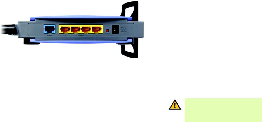
The Back Panel
The Router's ports, where the cables are connected, and Reset button are located on the back panel.
|
Figure 3-1: The Router’s Back Panel |
INTERNET |
The Internet port is where you will connect your broadband modem. |
ETHERNET 1, 2, 3, 4 These ports (1, 2, 3, 4) connect the Router to your wired PCs and other Ethernet network
|
devices. |
Reset Button |
There are two ways to reset the Router's factory defaults. Either press the Reset button, |
|
for approximately five seconds, or restore the defaults from the Administration - Factory |
|
Defaults tab of the Router's Web-based Utility. |
Power |
The Power port is where you will connect the power adapter. |
IMPORTANT: Resetting the Router will erase all of your settings (Internet connection, wireless security, and other settings) and replace them with the factory defaults. Do not reset the Router if you want to retain these settings.
Chapter 3: Getting to Know the Wireless-N Broadband Router |
6 |
The Back Panel
Wireless-N Broadband Router
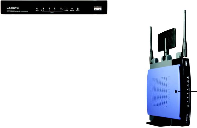
The Front Panel
The Router’s LEDs are located on the front panel.
|
Figure 3-2: The Router’s Front Panel |
POWER |
Green. The POWER LED lights up and will stay on while the Router is powered on. |
ETHERNET 1, 2, 3, 4 Green. These numbered LEDs, corresponding with the numbered ports on the Router’s
|
back panel, serve two purposes. The LED lights up when the Router is connected to a |
|
device through the corresponding port. If the LED is flashing, the Router is sending or |
|
receiving data over that port. |
INTERNET |
Green. The INTERNET LED lights up when there is a connection through the Internet port. |
WIRELESS |
Green. The WIRELESS LED lights up when there is a wireless connection. If the LED is |
|
flashing, the Router is sending or receiving data over the wireless network. |
SECURITY |
Green. The SECURITY LED indicates when wireless security is enabled. |
The Top Panel
The Router has a button reserved for a future function.
Chapter 3: Getting to Know the Wireless-N Broadband Router
Button
Figure 3-3: The Router’s Top Panel
7
The Front Panel
Wireless-N Broadband Router
Chapter 4: Connecting the Wireless-N Broadband Router
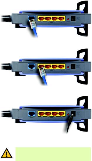
Hardware Installation
1.Make sure that all of your hardware is powered off, including the broadband modem and PCs.
2.Connect your broadband modem’s Ethernet cable to the Router’s Internet port.
3.Connect one end of an Ethernet network cable to one of the numbered ports on the back of the Router. Connect the other end to an Ethernet port on a network device, e.g., a PC, print server, or switch.
Repeat this step to connect more PCs or other network devices to the Router.
4.Power on the broadband modem.
5.Connect the included power adapter to the Router’s Power port, and then plug the power adapter into an electrical outlet. The Power LED on the front panel will light up when the adapter is connected properly.
6.Power on your PC(s).
7.Locate an optimum location for the Router. The best place for the Router is usually at the center of your wireless network, with line of sight to all of your wireless devices.
Proceed to “Chapter 5: Configuring the Wireless-N Broadband Router”.
Figure 4-1: Connect the Modem
Figure 4-2: Connect a PC
Figure 4-3: Connect the Power
IMPORTANT: Make sure you use the power adapter that is supplied with the Router. Use of a different power adapter could damage the Router.
Chapter 4: Connecting the Wireless-N Broadband Router |
8 |
Hardware Installation
Wireless-N Broadband Router
Chapter 5: Configuring the Wireless-N Broadband Router
Overview
Linksys recommends using the Setup CD-ROM for first-time installation of the Router. If you do not wish to run the Setup Wizard on the Setup CD-ROM, then you can use the Web-based Utility to configure the Router. For advanced users, you may configure the Router’s advanced settings through the Web-based Utility.
This chapter will describe each web page on the Utility and each page’s key functions. The Utility can be accessed via your web browser through use of a computer connected to the Router. For a basic network setup, most users only have to use the following screens of the Utility:
•Basic Setup. On the Basic Setup screen, enter the Internet connection settings provided by your Internet Service Provider (ISP). If you do not have this information, you can call your ISP to request the settings. When you have the setup information, then you can configure the Router.
•Management. Click the Administration tab and then the Management tab. The Router’s default password is admin. To secure the Router, change the Password from its default.
•Wireless. On the Basic Wireless Settings screen, set the basic configuration for your wireless network.
There are seven main tabs: Setup, Wireless, Security, Access Restrictions, Applications & Gaming, Administration, and Status. Additional tabs will be available after you click one of the main tabs.
Setup
•Basic Setup. Enter the Internet connection and network settings on this screen.
•DDNS. Enable the Router’s Dynamic Domain Name System (DDNS) feature on this screen.
•MAC Address Clone. If you need to clone a MAC address onto the Router, use this screen.
•Advanced Routing. Use this screen to alter dynamic and static routing configurations.
Wireless
•Basic Wireless Settings. Enter the basic settings for your wireless network on this screen.
•Wireless Security. Enable and configure the security settings for your wireless network.
Chapter 5: Configuring the Wireless-N Broadband Router |
9 |
Overview
Wireless-N Broadband Router
•Wireless MAC Filter. Wireless access can be filtered by using the MAC addresses of the wireless devices transmitting within your network’s radius.
•Advanced Wireless Settings. For advanced users, you can alter data transmission settings on this screen.
Security
•Firewall. You can enable or disable the Router’s firewall, as well as various filters.
•VPN Passthrough. To enable or disable IPSec, L2TP, and/or PPTP Passthrough, use this screen.
Access Restrictions
Internet Access Policy. Create policies to control Internet access for your local network users.
Applications & Gaming
•Single Port Forwarding. This allows you to do port mapping and forwarding for a single service port.
•Port Range Forwarding. Set up public services or other specialized Internet applications on your network.
•Port Range Triggering. Configure the Router to watch outgoing data for specific port numbers.
•DMZ. Click this tab to allow one local user to be exposed to the Internet for use of special-purpose services.
•QoS. Quality of Service (QoS) ensures better service to high-priority types of network traffic.
Administration
•Management. On this screen, alter the Router’s password, access privileges, and UPnP settings. You can also use this screen to back up and restore the Router’s configuration file.
•Log. If you want to view or save activity logs, click this tab.
•Diagnostics. If you want to run a ping or traceroute test, then use this screen.
•Factory Defaults. If you want to restore the Router’s factory defaults, then use this screen.
•Firmware Upgrade. Click this tab if you want to upgrade the Router’s firmware.
Chapter 5: Configuring the Wireless-N Broadband Router |
10 |
Overview
Wireless-N Broadband Router
Status
•Router. This screen provides status information about the Router.
•Local Network. This provides status information about the local network.
•Wireless Network. This provides status information about the wireless network.
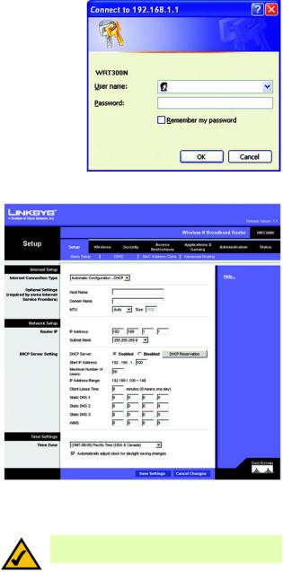
How to Access the Web-based Utility
To access the Web-based Utility of the Router, launch Internet Explorer or Netscape Navigator, and enter the Router’s default IP address, 192.168.1.1, in the Address field. Press the Enter key.
A screen will appear asking you for your User name and Password. Leave the User Name field blank. Enter admin in the Password field. Then click the OK button.
Make the necessary changes through the Utility. When you have finished making changes to a screen, click the Save Settings button to save the changes, or click the Cancel Changes button to undo your changes. For information on a tab, click Help.
The Setup Tab - Basic Setup
The Basic Setup screen is the first screen you see when you access the Web-based Utility.
Internet Setup
The Internet Setup section configures the Router for your Internet connection type. This information can be obtained from your ISP.
Internet Connection Type
The Router supports six connection types: Automatic Configuration - DHCP, Static IP, PPPoE, PPTP, Telstra Cable, and L2TP. Each Basic Setup screen and available features will differ depending on what kind of connection type you select.
Automatic Configuration - DHCP
By default, the Router’s Internet Connection Type is set to Automatic Configuration - DHCP, and it should be used only if your ISP supports DHCP or you are connecting through a dynamic IP address.
Chapter 5: Configuring the Wireless-N Broadband Router
Figure 5-1: Router Login
Figure 5-2: Setup Tab - Basic Setup
(Automatic Configuration - DHCP)
NOTE: Some of these connection types may not be available in your area.
11
How to Access the Web-based Utility
Wireless-N Broadband Router
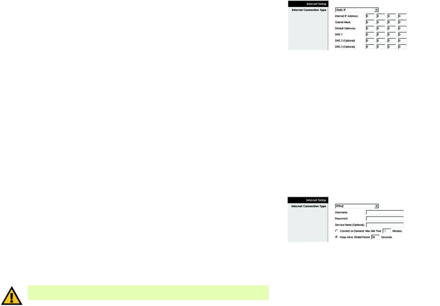
Static IP
If you are required to use a permanent IP address, then select Static IP.
Internet IP Address. This is the IP address that the Router has, when seen from the Internet. Your ISP will provide you with the IP address you need to specify here.
Subnet Mask. This is the Router’s Subnet Mask, as seen by external users on the Internet (including your ISP). Your ISP will provide you with the Subnet Mask.
Default Gateway. Your ISP will provide you with the Default Gateway Address.
DNS 1-3. Your ISP will provide you with at least one DNS (Domain Name System) Server IP Address.
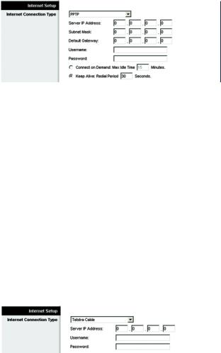
PPPoE
Some DSL-based ISPs use PPPoE (Point-to-Point Protocol over Ethernet) to establish Internet connections for end-users. If you use a DSL line, check with your ISP to see if they use PPPoE. If they do, you will have to enable it.
User Name and Password. Enter the User Name and Password provided by your ISP.
Service Name. If provided by your ISP, enter the Service Name.
Connect on Demand and Max Idle Time. You can configure the Router to cut the Internet connection after it has been inactive for a specific period of time (Max Idle Time). If your Internet connection has been terminated due to inactivity, Connect on Demand enables the Router to automatically re-establish your connection as soon as you attempt to access the Internet again. To use Connect on Demand, click the radio button. If you want your Internet connection to remain on at all times, enter 0 in the Max Idle Time field. Otherwise, enter the number of minutes you want to have elapsed before your Internet access disconnects.
Keep Alive and Redial Period. This option keeps your Internet access connected indefinitely, even when it sits idle. If you select this option, the Router will periodically check your Internet connection. If the connection is down, then the Router will automatically re-establish the connection. To use this option, click the radio button next to Keep Alive. The default Redial Period is 30 seconds.
Click the Save Settings button. Then click the Status tab, and click the Connect button.
IMPORTANT: For DSL users, if you need to enable PPPoE support, remember to remove any PPPoE applications that are installed on your PCs.
Chapter 5: Configuring the Wireless-N Broadband Router
Figure 5-3: Static IP
static ip address: a fixed address assigned to a computer or device connected to a network.
subnet mask: an address code that determines the size of the network
default gateway: a device that forwards Internet traffic from your local area network
Figure 5-4: PPPoE
pppoe: a type of broadband connection that provides authentication (username and password) in addition to data transport
12
The Setup Tab - Basic Setup
Wireless-N Broadband Router
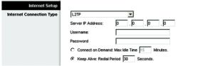
PPTP
Point-to-Point Tunneling Protocol (PPTP) is a service that applies to connections in Europe and Israel only.
Server IP Address. This is the IP address that the Router has, when seen from the Internet. Your ISP will provide you with the IP address you need to specify here.
Subnet Mask. This is the Router’s Subnet Mask, as seen by external users on the Internet (including your ISP). Your ISP will provide you with the Subnet Mask.
Default Gateway. Your ISP will provide you with the Default Gateway Address.
User Name and Password. Enter the User Name and Password provided by your ISP.
Connect on Demand and Max Idle Time. You can configure the Router to cut the Internet connection after it has been inactive for a specific period of time (Max Idle Time). If your Internet connection has been terminated due to inactivity, Connect on Demand enables the Router to automatically re-establish your connection as soon as you attempt to access the Internet again. To use Connect on Demand, click the radio button. If you want your Internet connection to remain on at all times, enter 0 in the Max Idle Time field. Otherwise, enter the number of minutes you want to have elapsed before your Internet access disconnects.
Keep Alive and Redial Period. This option keeps your Internet access connected indefinitely, even when it sits idle. If you select this option, the Router will periodically check your Internet connection. If the connection is down, then the Router will automatically re-establish the connection. To use this option, click the radio button next to Keep Alive. The default Redial Period is 30 seconds.
Click the Save Settings button. Then click the Status tab, and click the Connect button.
Telstra Cable
Telstra Cable is a service used in Australia only. Check with your ISP for the necessary setup information.
Server IP Address. This is the IP address that the Router has, when seen from the Internet. Your ISP will provide you with the IP address you need to specify here.
User Name and Password. Enter the User Name and Password provided by your ISP.
Click the Save Settings button. Then click the Status tab, and click the Connect button.
Chapter 5: Configuring the Wireless-N Broadband Router
Figure 5-5: PPTP
Figure 5-6: Telstra Cable
13
The Setup Tab - Basic Setup
Wireless-N Broadband Router
L2TP
Layer 2 Tunneling Protocol (L2TP) is a service that tunnels Point-to-Point Protocol (PPP) across the Internet. It is used mostly in European countries. Check with your ISP for the necessary setup information.
Server IP Address. This is the IP address that the Router has, when seen from the Internet. Your ISP will provide you with the IP address you need to specify here.
User Name and Password. Enter the User Name and Password provided by your ISP.
Connect on Demand and Max Idle Time. You can configure the Router to cut the Internet connection after it has been inactive for a specific period of time (Max Idle Time). If your Internet connection has been terminated due to inactivity, Connect on Demand enables the Router to automatically re-establish your connection as soon as you attempt to access the Internet again. To use Connect on Demand, click the radio button. If you want your Internet connection to remain on at all times, enter 0 in the Max Idle Time field. Otherwise, enter the number of minutes you want to have elapsed before your Internet access disconnects.
Keep Alive and Redial Period. This option keeps your Internet access connected indefinitely, even when it sits idle. If you select this option, the Router will periodically check your Internet connection. If the connection is down, then the Router will automatically re-establish the connection. To use this option, click the radio button next to Keep Alive. The default Redial Period is 30 seconds.
Click the Save Settings button. Then click the Status tab, and click the Connect button.
Optional Settings
Some of these settings may be required by your ISP. Verify with your ISP before making any changes.
Host Name and Domain Name. Some ISPs require these names as identification. You may have to check with your ISP to see if your broadband Internet service has been configured with a host and domain name. In most cases, leaving these fields blank will work.
MTU. The MTU (Maximum Transmission Unit) setting specifies the largest packet size permitted for network transmission. To manually set a value, select Manual and enter the value desired in the Size field. You should leave this value in the 1200 to 1500 range. Most DSL users should use the value 1492. The default is Auto, which allows the Router to select the best MTU for your Internet connection.
Chapter 5: Configuring the Wireless-N Broadband Router
Figure 5-7: L2TP
packet: a unit of data sent over a network.
14
The Setup Tab - Basic Setup
Wireless-N Broadband Router
Network Setup
The Network Setup section allows you to change the Router’s local network settings.
Router IP
The Router’s Local IP Address and Subnet Mask are shown here. In most cases, you should keep the defaults.
Local IP Address. The default value is 192.168.1.1.
Subnet Mask. The default value is 255.255.255.0.
DHCP Server Setting
The Router can be used as a Dynamic Host Configuration Protocol (DHCP) server for your network. A DHCP server automatically assigns an IP address to each computer on your network. Unless you already have one, it is highly recommended that you leave the Router enabled as a DHCP server.
DHCP Server. DHCP is enabled by factory default. If you already have a DHCP server on your network, set the Router’s DHCP option to Disabled. If you disable DHCP, remember to assign a static IP address to the Router.
Start IP Address. Enter a value for the DHCP server to start with when issuing IP addresses. Because the default IP address for the Router is 192.168.1.1, the Start IP Address must be 192.168.1. 2 or greater, but smaller than 192.168.1.254. The default Start IP Address is 192.168.1.100.
Maximum Number of Users (Optional). Enter the maximum number of PCs that you want the DHCP server to assign IP addresses to. This number cannot be greater than 253. The default is 50.
Client Lease Time. The Client Lease Time is the amount of time a network user will be allowed connection to the Router with their current dynamic IP address. Enter the amount of time, in minutes, that the user will be “leased” this dynamic IP address. After the dynamic IP address has expired, the user will be automatically assigned a new dynamic IP address. The default is 0 minutes, which means one day.
Static DNS 1-3. The Domain Name System (DNS) is how the Internet translates domain or website names into Internet addresses or URLs. Your ISP will provide you with at least one DNS Server IP Address. You can enter up to three DNS Server IP Addresses here. The Router will use these for quicker access to functioning DNS servers.
WINS. The Windows Internet Naming Service (WINS) converts NetBIOS names to IP addresses. If you use a WINS server, enter that server’s IP address here. Otherwise, leave this field blank.
dynamic ip address: a temporary IP address assigned by a DHCP server.
Chapter 5: Configuring the Wireless-N Broadband Router |
15 |
The Setup Tab - Basic Setup
Wireless-N Broadband Router
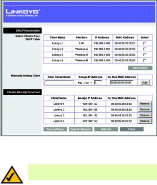
DHCP Reservation. Click the DHCP Reservation button if you want to assign a fixed local IP address to a MAC address. You will see a list of DHCP clients with the following information: Client Name, Interface, IP Address, and MAC Address. Click the Select checkbox to reserve a client’s IP address. Then click the Add Clients button.
If you want to manually assign an IP address, enter the client’s name in the Enter Client Name field. Enter the IP address you want it to have in the Assign IP Address field. Enter its MAC Address in the To This MAC Address field. Click the Add button.
A list of DHCP clients and their fixed local IP addresses will be displayed at the bottom of the screen. If you want to remove a client from this list, click the Remove button.
When you have finished your changes, click the Save Settings button to save your changes. Click the Cancel Changes button to cancel your changes. To view the most up-to-date information, click the Refresh button. To exit this screen, click the Close button.
Time Setting
Time Zone. Select the time zone in which your network functions. If you want the Router to automatically adjust the clock for daylight savings, then select the checkbox.
When you have finished making changes to this screen, click the Save Settings button to save the changes, or click the Cancel Changes button to undo your changes. For more information, click Help.
Chapter 5: Configuring the Wireless-N Broadband Router
Figure 5-8: DHCP Reservation
NOTE: To test your settings, connect to the Internet now.
16
The Setup Tab - Basic Setup
Wireless-N Broadband Router
The Setup Tab - DDNS
The Router offers a Dynamic Domain Name System (DDNS) feature. DDNS lets you assign a fixed host and domain name to a dynamic Internet IP address. It is useful when you are hosting your own website, FTP server, or other server behind the Router.
Before you can use this feature, you need to sign up for DDNS service at one of two DDNS service providers, DynDNS.org or TZO.com. If you do not want to use this feature, keep the default setting, Disable.
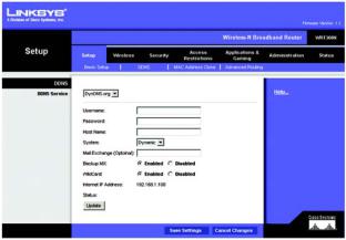
DDNS
DDNS Service
If your DDNS service is provided by DynDNS.org, then select DynDNS.org from the drop-down menu. If your DDNS service is provided by TZO, then select TZO.com. The features available on the DDNS screen will vary, depending on which DDNS service provider you use.
DynDNS.org
Username, Password, and Host Name. Enter the settings of the account you set up with DynDNS.org.
System. Select the DynDNS service you use: Dynamic, Static, or Custom.
Mail Exchange (Optional). Enter the address of your mail exchange server, so e-mails to your DynDNS address go to your mail server.
Backup MX. This feature allows the mail exchange server to be a backup. To enable this feature, keep the default, Enabled. To disable the feature, select Disabled. If you are not sure which setting to select, keep the default, Enabled.
WildCard. This setting enables or disables wildcards for your host. For example, if your DDNS address is myplace.dyndns.org and you enable wildcards, then x.myplace.dyndns.org will work as well (x is the wildcard). To enable wildcards, keep the default, Enabled. To disable wildcards, select Disabled. If you are not sure which setting to select, keep the default, Enabled.
Status. The status of the DDNS service connection is displayed here.
Update. To manually trigger an update, click this button.
Chapter 5: Configuring the Wireless-N Broadband Router
ddns: allows the hosting of a website, FTP server, or e-mail server with a fixed domain name (e.g., www.xyz.com) and a dynamic IP address.
17
The Setup Tab - DDNS
Wireless-N Broadband Router
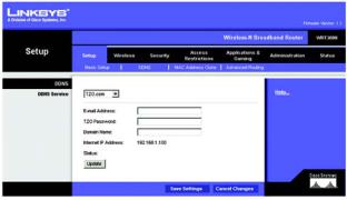
TZO.com
E-mail Address, TZO Password, and Domain Name. Enter the settings of the account you set up with TZO.
Internet IP Address. The Router’s Internet IP address is displayed here. Because it is dynamic, it will change.
Status. The status of the DDNS service connection is displayed here.
Update. To manually trigger an update, click this button.
When you have finished making changes to this screen, click the Save Settings button to save the changes, or click the Cancel Changes button to undo your changes. For more information, click Help.
Chapter 5: Configuring the Wireless-N Broadband Router
Figure 5-10: Setup Tab - DDNS (TZO.com)
18
The Setup Tab - DDNS
Wireless-N Broadband Router
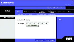
The Setup Tab - MAC Address Clone
A MAC address is a 12-digit code assigned to a unique piece of hardware for identification, like a social security number. Some ISPs will require you to register a MAC address in order to access the Internet. If you do not wish to re-register the MAC address with your ISP, you may assign the MAC address you have currently registered with your ISP to the Router with the MAC Address Clone feature.
MAC Address Clone
To use MAC address cloning, select Enabled. Otherwise, keep the default, Disabled.
MAC Address. Enter the MAC Address registered with your ISP.
Clone My PC’s MAC. If you want to clone the MAC address of the PC you are currently using to configure the Router, then click this button. The Router will automatically detect your PC’s MAC address, so you do NOT have to call your ISP to change the registered MAC address to the Router’s MAC address. It is recommended that the PC registered with the ISP is used to open the MAC Address Clone screen.
When you have finished making changes to this screen, click the Save Settings button to save the changes, or click the Cancel Changes button to undo your changes. For more information, click Help.
Chapter 5: Configuring the Wireless-N Broadband Router
Figure 5-11: Setup Tab - MAC Clone
mac address: the unique address that a manufacturer assigns to each networking device.
19
The Setup Tab - MAC Address Clone
Wireless-N Broadband Router
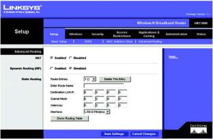
The Setup Tab - Advanced Routing
The Advanced Routing screen allows you to configure the dynamic and static routing settings.
Advanced Routing
NAT
If this Router is hosting your network’s connection to the Internet, select Enabled. If another Router exists on your network, select Disabled. When the NAT setting is disabled, dynamic routing will be enabled.
Dynamic Routing
This feature enables the Router to automatically adjust to physical changes in the network’s layout and exchange routing tables with the other router(s). The Router determines the network packets’ route based on the fewest number of hops between the source and the destination. To use dynamic routing, select Enabled. Otherwise, select Disabled. When the NAT setting is disabled, dynamic routing will be enabled.
Static Routing
A static route is a pre-determined pathway that network information must travel to reach a specific host or network. Use this feature to set up a static route between the Router and another network (you can have up to 20 static routes). To create a static route, alter the following settings:
Route Entries. Select the number of the static route from the drop-down menu.
Enter Route Name. Enter a name for the static route, using a maximum of 25 alphanumeric characters.
Destination LAN IP. The Destination LAN IP Address is the address of the remote network or host to which you want to assign a static route. Enter the IP address of the host for which you wish to create a static route.
Subnet Mask. The Subnet Mask determines which portion of a Destination IP address is the network portion, and which portion is the host portion.
Default Gateway. This is the IP address of the gateway device that allows for contact between the Router and the remote network or host.
Interface. Select LAN & Wireless or WAN (Internet), depending on the location of the final destination.
Delete This Entry. To delete a route, select its number from the drop-down menu, and click this button.
Chapter 5: Configuring the Wireless-N Broadband Router
Figure 5-12: Setup Tab - Advanced Routing
20
The Setup Tab - Advanced Routing
Wireless-N Broadband Router
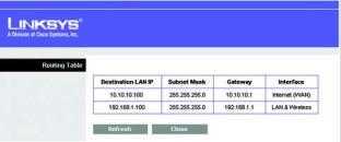
Show Routing Table. Click the Show Routing Table button to open a screen displaying how data is routed through your local network. For each route, the Destination LAN IP address, Subnet Mask, Gateway, and Interface are displayed. Click the Refresh button to update the information. Click the Close button to exit this screen.
When you have finished making changes to this screen, click the Save Settings button to save the changes, or click the Cancel Changes button to undo your changes. For more information, click Help.
Chapter 5: Configuring the Wireless-N Broadband Router
Figure 5-13: Routing Table
21
The Setup Tab - Advanced Routing
Loading...