


Owner’s manual
E 1

Precautions
Location
Using the unit in the following locations can result in a malfunction.
•In direct sunlight
•Locations of extreme temperature or humidity
•Excessively dusty or dirty locations
•Locations of excessive vibration
•Close to magnetic fields
Power supply
Please connect the designated AC adapter to an AC outlet of the correct voltage. Do not connect it to an AC outlet of voltage other than that for which your unit is intended.
Interference with other electrical devices
Radios and televisions placed nearby may experience reception interference. Operate this unit at a suitable distance from radios and televisions.
Handling
To avoid breakage, do not apply excessive force to the switches or controls.
Care
If the exterior becomes dirty, wipe it with a clean, dry cloth. Do not use liquid cleaners such as benzene or thinner, or cleaning compounds or flammable polishes.
Keep this manual
After reading this manual, please keep it for later reference.
Keeping foreign matter out of your equipment
Never set any container with liquid in it near this equipment. If liquid gets into the equipment, it could cause a breakdown, fire, or electrical shock.
Be careful not to let metal objects get into the equipment. If something does slip into the equipment, unplug the AC adapter from the wall outlet. Then contact your nearest Korg dealer or the store where the equipment was purchased.
THE FCC REGULATION WARNING (for U.S.A.)
This equipment has been tested and found to comply with the limits for a Class B digital device, pursuant to Part 15 of the FCC Rules. These limits are designed to provide reasonable protection against harmful interference in a residential installation. This equipment generates, uses, and can radiate radio frequency energy and, if not installed and used in accordance with the instructions, may cause harmful interference to radio communications. However, there is no guarantee that interference will not occur in a particular installation. If this equipment does cause harmful interference to radio or television reception, which can be determined by turning the equipment off and on, the user is encouraged to try to correct the interference by one or more of the following measures:
•Reorient or relocate the receiving antenna.
•Increase the separation between the equipment and receiver.
•Connect the equipment into an outlet on a circuit different from that to which the receiver is connected.
•Consult the dealer or an experienced radio/TV technician for help. Unauthorized changes or modification to this system can void the user’s authority to operate this equipment.
CE mark for European Harmonized Standards
CE mark which is attached to our company’s products of AC mains operated apparatus until December 31, 1996 means it conforms to EMC Directive (89/
336/EEC) and CE mark Directive (93/68/EEC). And, CE mark which is attached after January 1, 1997 means it conforms to EMC Directive (89/336/ EEC), CE mark Directive (93/68/EEC) and Low Voltage Directive (73/23/EEC). Also, CE mark which is attached to our company’s products of Battery operated apparatus means it conforms to EMC Directive (89/336/EEC) and CE mark Directive (93/68/EEC).
ii
About your data
Inadvertent operations or unexpected malfunctions may cause the contents of memory to be lost. To safeguard your important data, please save it on your computer. Korg will accept no responsibility for any damages resulting from loss of data.
About the software license agreement
You must read the separate “Software license agreement” before you install the software for this product. Installing this software will be considered as your acceptance of this agreement.
*Microsoft and Windows are registered trademarks of Microsoft Corporation USA in the United States and other countries.
*Apple and Macintosh are registered trademarks of Apple Computer Corporation USA in the United states and other countries.
*Mac OS is a registered trademark of Apple Computer Corporation.
*Other names of companies, products, or standards are the trademarks or registered trademarks of their respective owners.
Conventions in this manual
Encoders and keys [ ]
Encoders and keys on the microKONTROL’s panel are enclosed in square brackets [ ].
Parameters “ ”
Parameters are enclosed in double quotation marks “ ”.
 and
and  symbols
These symbols respectively indicate a point of caution and a note of advice.
About the example displays
Parameter values etc. in the sample displays printed in this manual are only examples; they will not necessarily match the displays on your microKONTROL.
iii

Table of Contents |
|
Table of Contents |
|
Contents of the package .............................................. |
vi |
Introduction........................................................ |
1 |
Main features.............................................................. |
1 |
Parts and what they do ............................................... |
2 |
Front panel ............................................................................... |
2 |
Rear panel................................................................................ |
5 |
Driver installation and settings ..................................... |
6 |
Windows XP users .................................................................... |
6 |
■ Installing the Korg USB-MIDI Driver .................................... |
6 |
■ Uninstalling the Korg USB-MIDI Driver............................... |
9 |
■ Allowing installation of an unsigned driver....................... |
10 |
Mac OS X users ...................................................................... |
11 |
Mac OS X MIDI input and output ports.................................. |
11 |
Making connections and turning the power on ........... |
12 |
MIDI & AC adapter connection ................................................ |
12 |
Using Batteries............................................................................. |
12 |
USB connection ....................................................................... |
13 |
Operation........................................................ |
14 |
|
About the microKONTROL’s modes ............................ |
14 |
|
1. Play mode................................................................................. |
14 |
|
2. |
Setting mode ............................................................................ |
14 |
3. Message mode ......................................................................... |
14 |
|
4. Scene mode .............................................................................. |
14 |
|
Quick Start................................................................ |
15 |
|
1. Turning on the power............................................................. |
15 |
|
2. Selecting a scene ...................................................................... |
15 |
|
3. Making controller assignments ............................................. |
15 |
|
4. Saving a scene .......................................................................... |
17 |
|
5. Managing scene sets on your computer .............................. |
18 |
|
Play mode................................................................. |
19 |
|
Using the controllers ............................................................... |
19 |
|
1. |
Encoders and sliders............................................................... |
19 |
2. |
Trigger pads............................................................................. |
20 |
3. |
Joystick...................................................................................... |
21 |
4. Pedal (PEDAL jack)................................................................. |
22 |
|
5. Keyboard .................................................................................. |
22 |
|
6. |
[VALUE] dial ........................................................................... |
23 |
Setting mode............................................................. |
24 |
|
|
Scene parameter settings........................................................ |
24 |
|
Global parameter settings ...................................................... |
24 |
iv

About the OCTAVE SHIFT/CURSOR keys, [ENTER] key, |
|
and [EXIT] key......................................................................... |
24 |
[1] ENCODER (Encoder assignment).......................................... |
25 |
■ Assigning NRPN or RPN .................................................. |
26 |
Quick-assign for control changes ............................................. |
27 |
[2] SLIDER (Slider assignment) .................................................. |
27 |
[3] PAD (PAD assignment)........................................................ |
28 |
[4] PEDAL (Pedal assignment) ................................................... |
29 |
■ Assigning a control change ............................................... |
30 |
[5] JOYSTICK-X (Joystick–X assignment) ................................... |
31 |
Assigning a single MIDI message to the +X and |
|
–X directions................................................................................ |
31 |
■ Assigning aftertouch .......................................................... |
32 |
■ Assigning velocity .............................................................. |
33 |
■ Assigning a control change ............................................... |
33 |
Assigning different MIDI messages to the +X and –X |
|
directions...................................................................................... |
34 |
[6] JOYSTICK-Y (Joystick–Y assignment).................................... |
35 |
[7] STICK SW (Joystick switch assignment) ................................ |
35 |
[8] PORT (USB-MIDI Port setting)............................................... |
36 |
About the microKONTROL and the driver ports.................. |
37 |
MIDI IN devices...................................................................... |
37 |
MIDI OUT devices.................................................................. |
37 |
Mac OS X port numbers......................................................... |
37 |
About the microKONTROL’s MIDI connectors..................... |
37 |
When not connected via USB................................................ |
37 |
When connected via USB....................................................... |
37 |
[9] KBD VELOCITY (Keyboard Velocity setting) .......................... |
38 |
[10] PAD VELOCITY (PAD Velocity setting)................................. |
39 |
[11] LCD BACKLIG (LCD Backlight setting) ................................. |
39 |
[12] PAD ILLUMI (PAD Illumination setting)................................ |
40 |
|
Table of Contents |
[13] TRANSPOSE (Transpose setting) ........................................ |
40 |
[14] GLOB.CH (Global MIDI Channel setting)............................. |
41 |
[15] POLARITY (Polarity setting)................................................ |
41 |
[16] SYSTEM (System setting) ................................................... |
41 |
Message mode .......................................................... |
42 |
[1] PANIC (Panic message)....................................................... |
43 |
[2] SNAP (Snap message) ........................................................ |
43 |
[3] NOTE OFF (All Note Off message) ....................................... |
44 |
[4] GM ON (GM On message).................................................. |
44 |
[5] STOP (Stop message) .......................................................... |
44 |
[6] START (Start message) ........................................................ |
44 |
[7] CONTINUE (Continue message)........................................... |
45 |
[8] TAP (Tap message) ............................................................. |
45 |
[9] CTRL (Control Change message) .......................................... |
45 |
[10] BANK (Bank Select message) ............................................ |
46 |
[11] PROG (Program Change message) .................................... |
47 |
[12] BEND (Pitch Bend Change message) .................................. |
47 |
[13] RPN (RPN message).......................................................... |
48 |
[14] NRPN (NRPN message) .................................................... |
49 |
[15] EX (System Exclusive message).......................................... |
50 |
[16] FREE (Free message) ......................................................... |
51 |
Scene mode ............................................................... |
52 |
[1]...[12] Select Scene .............................................................. |
52 |
[13] VALUE (Encoder/Slider Value)........................................... |
52 |
[14] DUMP .............................................................................. |
53 |
[15] PRELOAD ......................................................................... |
53 |
[16] WRITE.............................................................................. |
54 |
v

Table of Contents |
|
Appendices ...................................................... |
55 |
Available MIDI messages........................................... |
55 |
Channel messages ................................................................... |
55 |
System Realtime messages..................................................... |
55 |
MIDI Control Change messages ........................................... |
55 |
Channel Mode messages........................................................ |
56 |
RPN MSB/LSB ........................................................................ |
56 |
Note no. .................................................................................... |
56 |
Using the Librarian software ...................................... |
57 |
Parts and their function ........................................................... |
57 |
Installation.............................................................................. |
57 |
Saving scenes on your computer.............................................. |
58 |
About the data you can save ................................................. |
58 |
Loading scenes into the microKONTROL................................... |
58 |
Menu commands .................................................................... |
59 |
Main shortcut keys.................................................................. |
60 |
MIDI implementation ................................................. |
61 |
System exclusive messages........................................................ |
61 |
About native Korg mode............................................ |
62 |
Operation in native mode.......................................................... |
62 |
Troubleshooting ........................................................ |
63 |
Main specifications.................................................... |
64 |
Index ........................................................................ |
65 |
Contents of the package
The microKONTROL comes with the following items.
When you open the package, make sure that all of these items are present. If any items are missing, please contact your Korg distributor.
The microKONTROL (main unit)
AC adaptor
This supplies power to the microKONTROL. Use the AC adaptor if you will be connecting a MIDI sound module etc. to the microKONTROL via MIDI. ( p.12 “Making connections and turning the power on”)
USB cable
Use this to connect the microKONTROL to your computer. ( p.12 “Making connections and turning the power on”)
CD-ROM
This contains a driver for your computer (Windows XP only) and librarian software.
 Never attempt to play back the CD-ROM on audio CD player. Doing so may result in damage to your hearing as well as to your CD player/ audio speakers.
Trigger pad name sheet/labels
You can affix labels to the name sheet to indicate the MIDI messages or controlled content assigned to each of the microKONTROL’s trigger pads, and place the sheet over the trigger pad section. This is a convenient way to remember what is assigned to each of the sixteen trigger pads.
Owner’s manual, MIDI Implementation chart/Name List
Software license agreement
vi

Introduction
Main features
The microKONTROL is a compact MIDI controller with all of the controllers you need for computer-based music production and performance. It has a three-octave keyboard, eight rotary encoders, eight sliders, and sixteen trigger pads, and lets you freely control soft synthesizers and DAW (Digital Audio Workstation) software, as well as external MIDI sound modules or other equipment.
Eight encoders and eight sliders
You can assign MIDI control change messages (including NRPN or RPN) to the eight encoders and sliders. The encoders and sliders have “sub-displays” that indicate the parameter name and value, and you can even specify the display backlight color to distinguish between different control assignments.
Sixteen velocity-sensitive trigger pads
You can use the velocity-sensitive pads for playing and programming drums, or any other sounds for that matter. The pads aren’t limited to sending notes, though - you can also use them to send MIDI control change messages, for remote control of your software’s Play/Stop/Rec transport – or virtually anything else! The pads can also be used for switching between microKONTROL setups, called “scenes.”
Assignable joystick with switch
You can assign messages like pitch bend to the X-axis and modulation to the Y-axis, or assign different MIDI messages to each of the four directions and the switch.
Introduction–Main features
37-note velocity-sensitive mini-keyboard
Use of a mini-keyboard keeps the microKONTROL extremely compact, while the Octave Shift and Transpose functions let you access the full range of notes. You can choose from eight velocity curves to select the response that’s right for your playing.
Easy parameter assignments
The displays provide plenty of information, making it easy to assign MIDI messages to each controller.
Twelve user memories
You can set up the microKONTROL’s controllers to match your soft synthesizer or DAW, and save these settings in memory as one of twelve “scenes.” Using the trigger pads, you can switch instantly between saved scenes.
The microKONTROL also contains pre-loaded scenes suitable for controlling popular sequencer software and soft synthesizers.
Included librarian software and template scene data
The microKONTROL comes with librarian software that makes it easy to manage scene data on your computer, and a variety of template scene data for popular sequencer software and soft synthesizers. The librarian software works seamlessly with the microKONTROL, letting you flexibly modify the template scenes or create your own original scenes to suit your setup and situation.
Bus-powered or battery-powered
The microKONTROL can be powered from the USB bus. If the microKONTROL is connected to your computer via USB, it will not require power from the AC adapter. Alternatively, it also gives you the flexibility of running on batteries.
Main features
1
Introduction–Parts and what they do
Parts and what they do
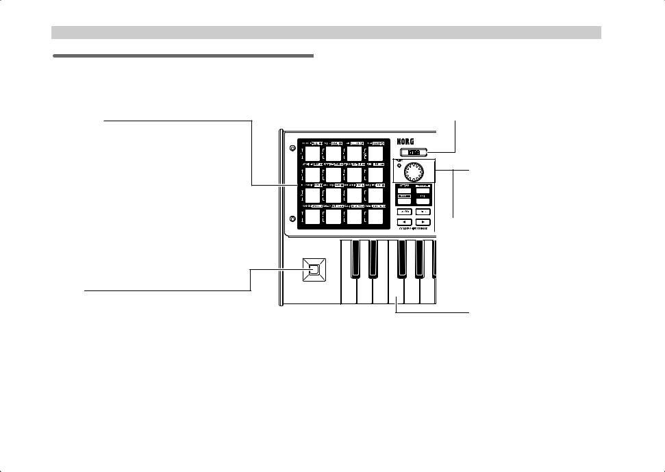
Front panel
Trigger pads
You can assign control changes or note messages (C-1– G9) to the trigger pads.
When assigning a control change, you can choose to transmit a value of 127 when the pad is pressed and 0 when released, or alternately transmit values of 0 and 127 each time the pad is pressed.
When assigning a note message, you can specify whether a note-on (with velocity) will be transmitted when the pad is pressed and a note-off when released, or alternately transmit both note-on and note-off messages each time the pad is pressed.
In other modes, you can use the trigger pads to select pages, to input numerical values, or perform various other functions depending on the mode. ( p.4 “About the trigger pad functions”)
Joystick
This is a joystick combined with a built-in switch. You can assign various MIDI messages to both the switch and the forward/ back/left/right (±Y, ±X) directions of the joystick, to control connected equipment or applications on your computer.
•You can assign aftertouch, velocity, pitch bend, master balance, or control changes to the ±X and ±Y directions.
•You can assign aftertouch, velocity, or control changes to each of the +X, –X, +Y, and –Y directions.
•You can assign control changes to the switch. You can specify whether a control change value of 127 will be transmitted when the switch is pressed and a value of 0 when released, or whether values of 0 and 127 will be transmitted alternately each time you press the switch.
 Main display
In each mode this displays the scene name, page, parameters, and other information.
[VALUE] dial
In Play mode, this adjusts the MIDI Clock tempo. In other modes, use this to set parameter values.
 TEMPO LED
The TEMPO LED blinks every quarter-note, according to the MIDI Clock tempo specified by the [VALUE] dial.
Keyboard
This is a 37-note velocity-sensitive mini-keyboard. It transmits note data on the global MIDI channel ( p.41).
2
|
|
Introduction–Parts and what they do |
|
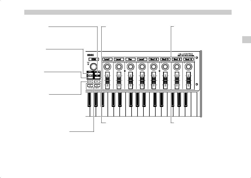
[MESSAGE] key |
[EXIT] key |
Sub-displays |
|
To enter Message mode, hold down this key |
Press this key to return to Play mode from |
These show the names assigned to each |
|
and press the trigger pad for the desired |
Setting, Message, or Scene modes, or to |
encoder and slider, or the values that are |
|
page. |
cancel a setting or operation. |
transmitted when they are moved. |
|
[SETTING] key |
|
|
|
To enter Setting mode, hold down this key |
|
|
|
and press the trigger pad for the desired |
|
|
|
page. |
|
|
|
[SCENE] key |
|
|
|
To enter Scene mode, hold down this key |
|
|
|
and press the trigger pad for the desired |
|
|
|
page. |
|
|
|
[HEX LOCK] key |
|
|
|
Press this key to enable and disable HEX |
|
|
|
LOCK mode. When it’s enabled, the LED |
|
|
|
will light up, and you can then use the |
|
|
|
trigger pads to input hexadecimal values. |
|
|
|
Also, MIDI messages and values shown in |
|
|
|
the main display and sub-displays will be |
|
|
|
shown in hexadecimal form. |
[ENTER] key |
Encoders and sliders |
|
|
|||
|
In Setting mode, press this key to finalize a |
You can assign a different MIDI message to |
|
OCTAVE SHIFT/CURSOR keys |
setting or value. |
each encoder and slider, and use them to |
|
In Play mode, these function as Octave Shift |
In Message mode, press this key to transmit |
control connected devices, soft |
|
the specified MIDI message. |
synthesizers, and DAW programs on your |
||
keys to shift the octave of the keyboard. |
|||
|
|
( p.22) |
computer. |
|
You can assign control change messages |
||
In other modes, the LEDs on both keys will |
||
(including RPN and NRPN) to the |
||
turn on, and you can then use them as |
||
encoders and sliders. |
||
cursor keys when you make parameter |
||
|
||
settings, etc. |
|
Parts and what they do
3
Introduction–Parts and what they do
About the trigger pad functions
The trigger pads are one of the most useful parts of the microKONTROL. They’re used for many different important functions, as described below.
Transmit MIDI messages
In Play mode, the MIDI message assigned in Setting mode will be transmitted each time you press a pad.
In Message mode, you can hold down the [MESSAGE] key and press a pad to transmit a specified MIDI message.
Select the different microKONTROL modes
To move from Play mode to Message, Setting, or Scene modes, hold down a mode key and press the appropriate pad to move to that mode, or to transmit a MIDI message.
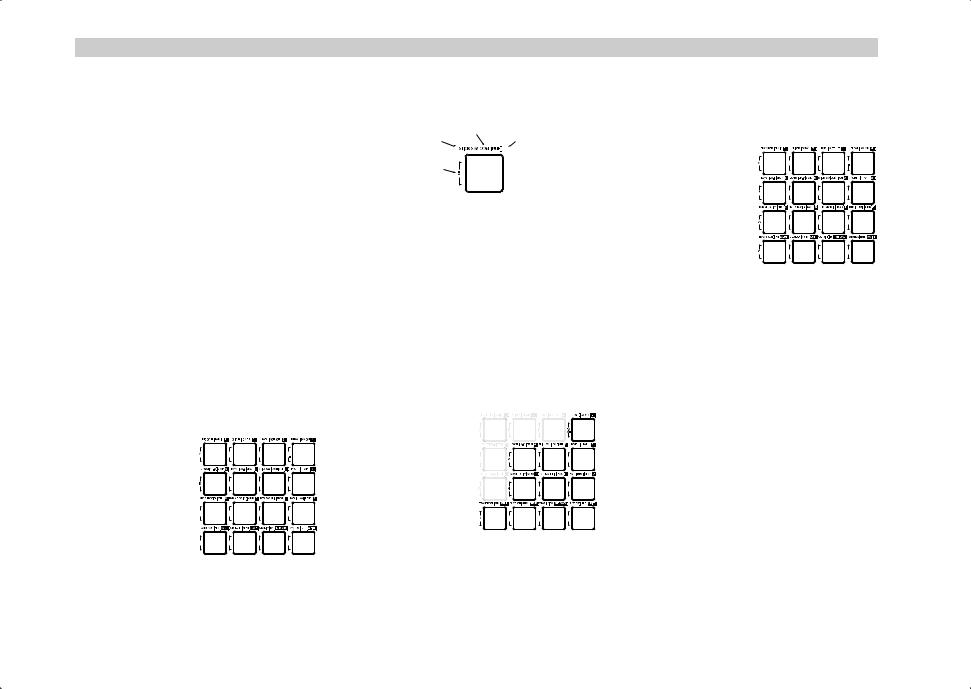
About the pad numbers
The pad numbers printed in this owner’s manual (e.g., pad [1]) correspond to the microKONTROL’s pads as follows.
[1]  [2]
[2]  [3]
[3]  [4]
[4]
[5]  [6]
[6]  [7]
[7]  [8]
[8]
 [9]
[9]  [10]
[10]  [11]
[11]  [12]
[12]
 [13]
[13]  [14]
[14]  [15]
[15]  [16]
[16]
The printing around each pad on the microKONTROL’s panel indicates the page or function in each mode.
Message mode
Setting mode |
|
Scene mode |
||
|
|
|
|
|
Numeric key or HEX key
Input numerical values
In Setting, Message, or Scene modes, you will use the pads to input numerical values such as MIDI control change numbers or MIDI channels.
You can input values in either decimal or hexadecimal form.
Using the pads to input decimal values
To input a decimal value, make sure that the [HEX LOCK] key is unlit, and use the pads shown below. The value will be cleared if you press any other pad.
-
7  8
8  9
9
4  5
5  6
6
0  1
1  2
2  3
3
Using the pads to input hexadecimal values
To input a hexadecimal value, press the [HEX LOCK] key to make it light, and use the pads shown below.
C  D
D  E
E  F
F
B  7
7  8
8  9
9
A  4
4  5
5  6
6
0  1
1  2
2  3
3
4
Rear panel
[Contrast adjustment] knob 
This adjusts the display contrast. The visibility of the display will vary depending on your viewing angle. Adjust this knob as necessary.
PEDAL jack
A damper pedal or pedal switch can be connected to this jack. You can assign a control change to the connected pedal. You can specify whether the pedal will transmit a control change value of 127 when pressed and 0 when released, or alternately transmit 0 and 127 each time it is pressed.
Introduction–Parts and what they do
Power switch
This switch powers-on the microKONTROL. Set the switch to the appropriate position for the type of power connection you are using. ( p.12 “Making connections and turning the power on”)
Parts and what they do
USB connector
Use a USB cable to connect the microKONTROL to your computer for MIDI message transmission and reception.
MIDI connectors 
You can connect external MIDI devices to these connectors, for sending and receiving MIDI messages. When connected to a computer via USB, you can also use these as MIDI ports for your computer.
Power supply connector
Connect the included AC adapter here.
Use the AC adapter if you are using the MIDI connectors to control a connected device. If you use a USB cable to connect the microKONTROL to your computer, power will be supplied from the computer (USB bus power) and the AC adapter will not be necessary.
 Some computers may not be able to supply power via USB bus power. In this case, use a self-powered USB hub (that obtains power from an external supply) or use the AC adapter.
5
Introduction–Driver installation and settings
Then the default driver will be installed.
Driver installation and settings
Windows XP users
■ Installing the Korg USB-MIDI Driver
In order to install (or uninstall) the driver in Windows XP, you must |
2 |
From the taskbar, click [Start] [Control Panel] to open the Control |
have Administrator privileges. For details, contact your system |
Panel. |
|
administrator. |
|
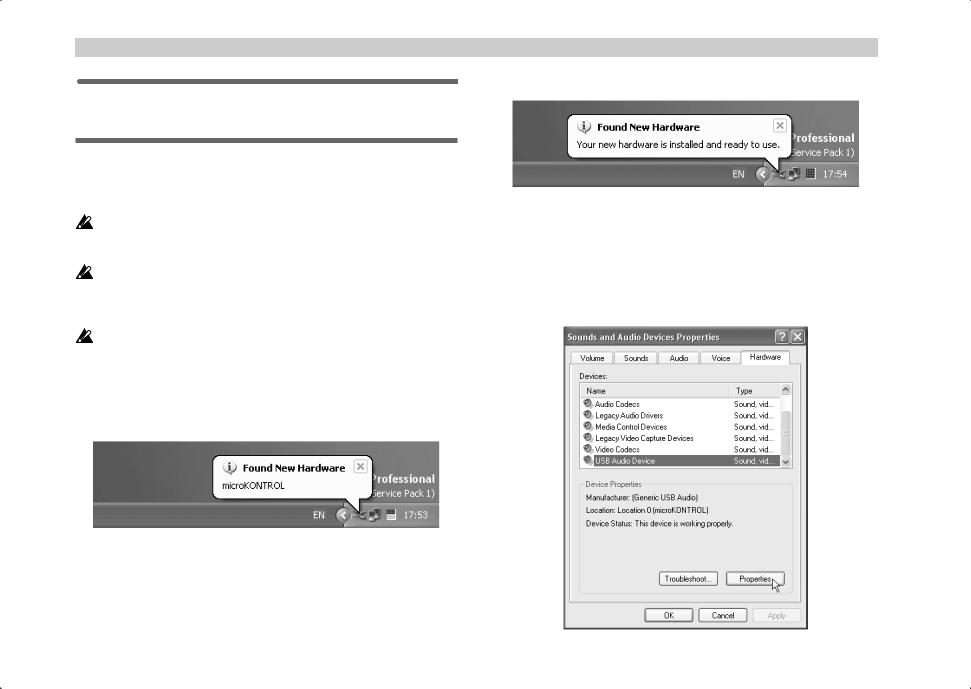
From the Control Panel, start up [Sounds and Audio Devices], and |
|
|
click the [Hardware] tab. |
If you encounter problems during installation, you may need to make |
From the list of devices, select [USB Audio Device]. Make sure that the |
|
settings so that Windows will not stop you from installing the driver |
||
“Location” field below the list shows “microKONTROL,” and click the |
||
due to its lack of a digital signature. For more information, see |
||
[Properties] button. |
||
“ Allowing installation of an unsigned driver” ( p.10). |
||
|
||
This driver is for Windows XP only. It cannot be used in Windows 95/ |
|
|
98/Me/2000. |
|
|
1 Use a USB cable to connect the microKONTROL to your computer, and |
|
turn on the power of the microKONTROL. ( p.12 “Making connections and turning the power on”)
Windows will detect the connection with the microKONTROL.
6
|
|
|
Introduction–Driver installation and settings |
3 |
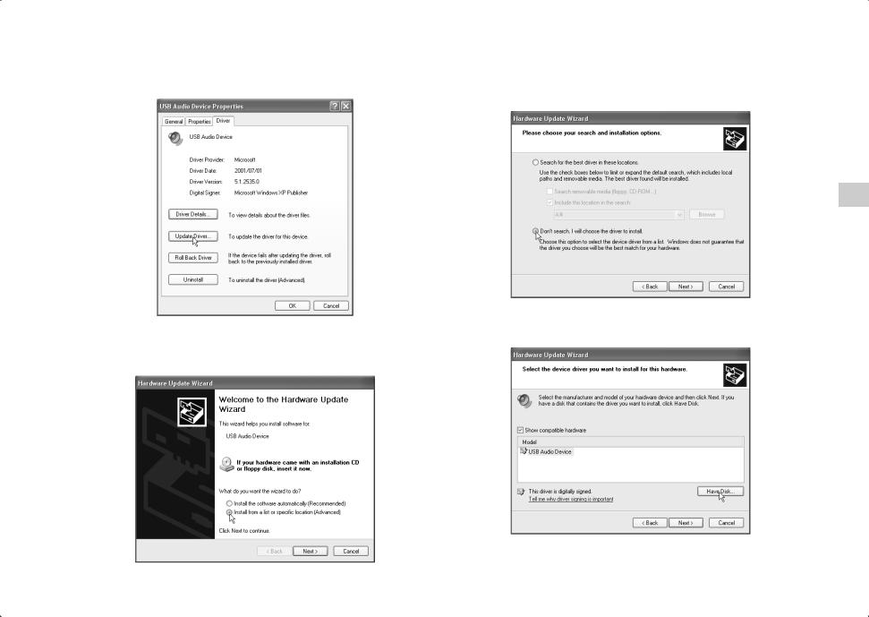
The “USB Audio Device Properties” dialog box will appear. Click the |
5 |
In response to “Please choose your search and installation options”, |
|
[Driver] tab, and then click the [Update Driver...] button. |
|
you must click “Don’t search. I will choose the driver to install,” and |
then click [Next>].
|
6 |
In response to “Select the device driver you want to install for this |
4 |
The “Hardware Update Wizard” will appear. |
hardware,” click the [Have Disk...] button. |
|
||
|
In the “What do you want the wizard to do?” field, click “Install from |
|
a list or specific location” and then click [Next>].
Driver installation and settings
7
Introduction–Driver installation and settings
7 |
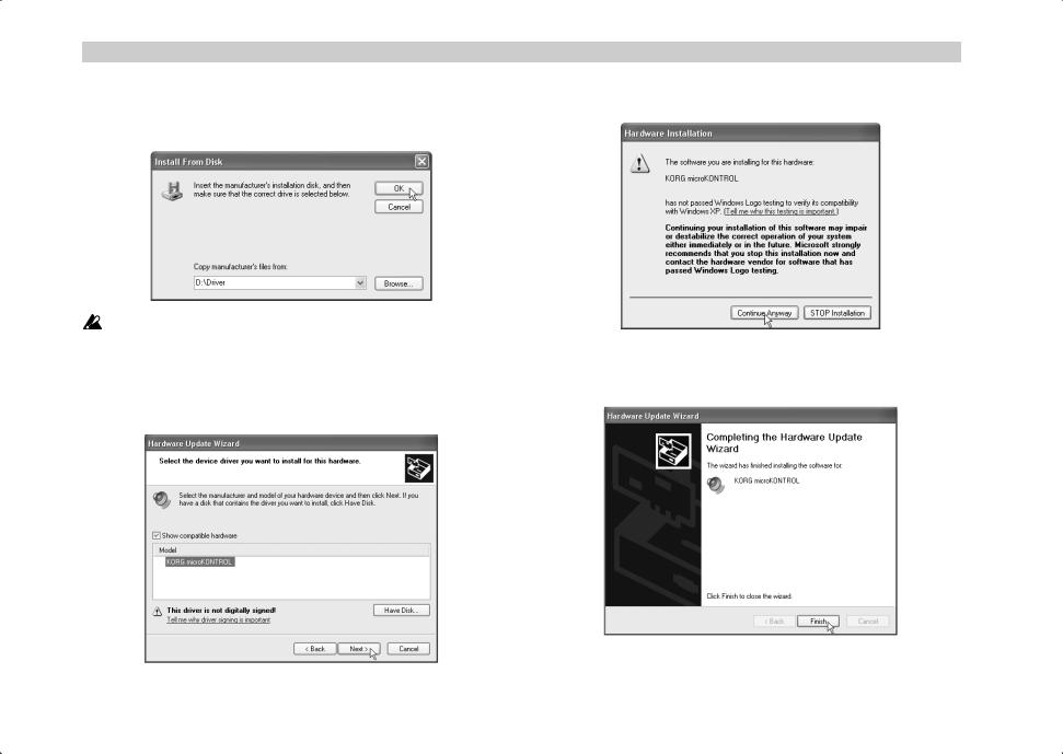
You will be asked for the name of the folder. Insert the CD-ROM |
|
included with the microKONTROL into your CD-ROM drive. Then |
type the name of the folder “D:\Driver” that contains the KORG USBMIDI driver, and click the [OK] button.
|
The above example is for when your CD-ROM drive is drive “D”. You |
|
will need to change this as appropriate for your computer system; for |
|
example, if your CD-ROM drive is drive “E”, then replace “D:” with |
|
“E:” in the folder name you type. |
8 |
Make sure that KORG microKONTROL is displayed as the Model, |
|
and click [Next>] to begin installing the driver. |
9 |
If a dialog box appears, warning you that the driver is not digitally |
|
signed, click [Continue Anyway]. |
10 When the dialog box indicating that installation is completed appears, click [Finish]. If a dialog box recommends that you restart Windows, click [Yes] to restart.
8
■ Uninstalling the Korg USB-MIDI Driver
If necessary, you can uninstall the Korg USB-MIDI Driver by following the steps below.
1 |
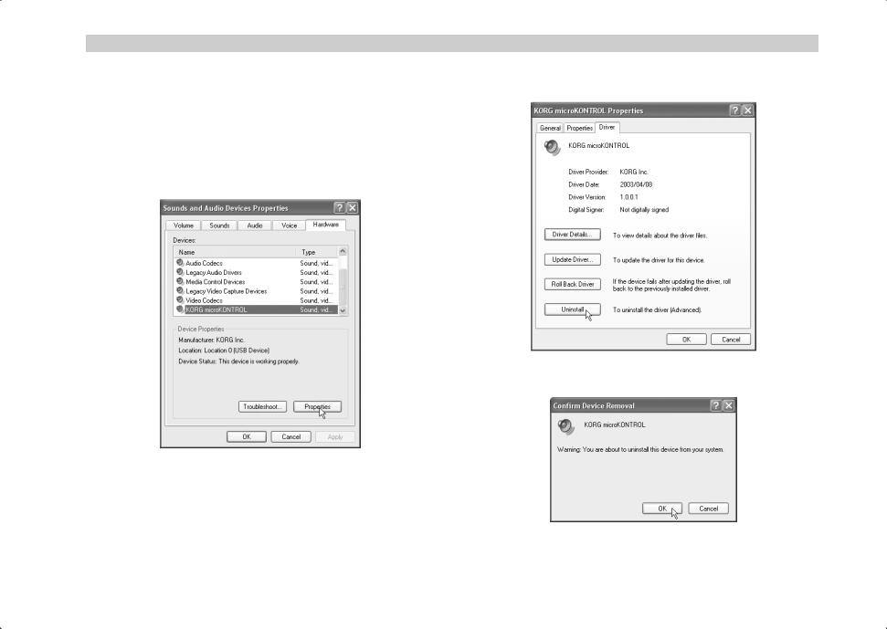
From the taskbar, click [Start] and then click [Control Panel] to open it. |
|
From the Control Panel, open [Sounds and Audio Devices], and click |
the [Hardware] tab.
From the list of devices, make sure that microKONTROL is shown for “Location,” and click the [Properties...] button.
|
Introduction–Driver installation and settings |
|
2 |
The “KORG microKONTROL Properties” dialog box will appear. Click |
|
|
the “Driver” tab, and click the [Uninstall] button. |
|
|
|
|
|
|
|
Driver installation and settings
3 A dialog box will ask you for confirmation. Click the [OK] button.
9
Introduction–Driver installation and settings
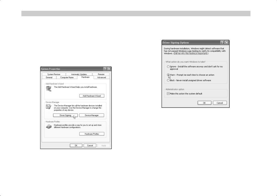
■ Allowing installation of an unsigned driver
If your computer has been set so that drivers without a digital signature cannot be installed, you will not be able to install the Korg USB-MIDI Driver. Use the following procedure to change your settings so that you can install the driver.
1 |
On the taskbar, click the [Start] button and then [Control Panel] to |
|
open the Control Panel. |
From the Control Panel, open [System] and click the [Hardware] tab. Then click the [Driver Signing] button.
2 If “What action do you want Windows to take?” is set to [Block], you will not be able to install the driver. Choose [Ignore] or [Warn], and then click [OK]. If necessary, change this setting back to its original setting after you have installed the driver.
10
Mac OS X users
When used with Mac OS X, the microKONTROL will automatically use Mac OS X’s built-in MIDI driver.
 For use with Mac OS X, the microKONTROL requires Mac OS X 10.2 or later.
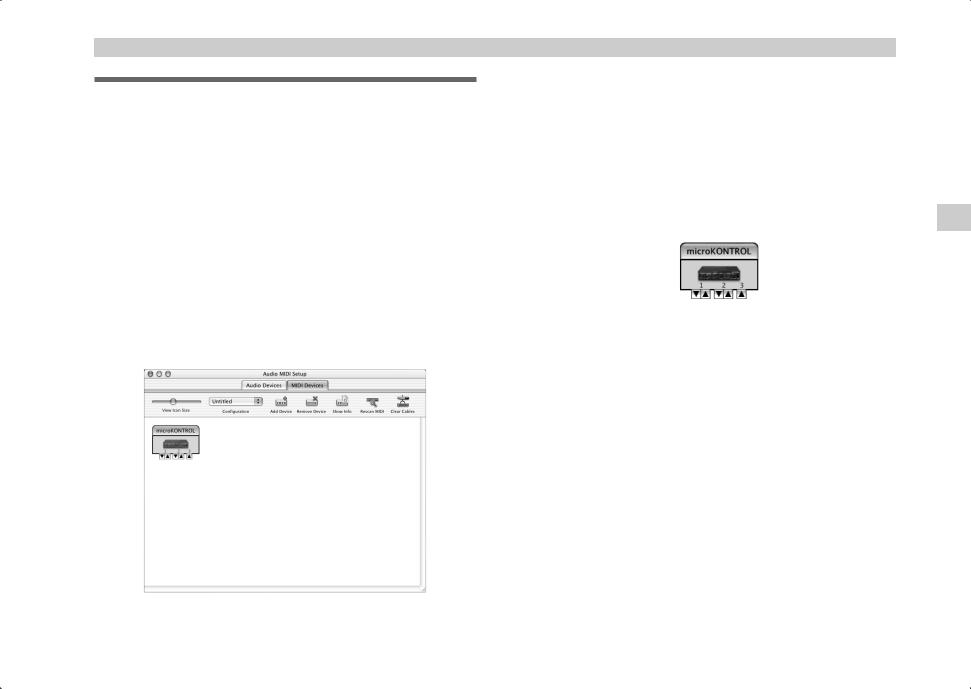
To set up the microKONTROL for use with Mac OS X, follow the steps below.
1 |
Use a USB cable to connect the microKONTROL to your computer. |
2 |
Turn on the power of the microKONTROL. |
3 |
Navigate to Macintosh HD Application folder Utility folder, and |
|
double-click “Audio MIDI Settings.” |
4 |
Click the “MIDI Devices” tab, and verify that the microKONTROL is |
|
displayed. |
Introduction–Driver installation and settings
Mac OS X MIDI input and output ports
Using the Mac OS X MIDI drivers, the microKONTROL provides a total of three MIDI inputs and two MIDI outputs, as follows:
•One port each of MIDI input and output for external devices
•Two ports of MIDI input from the microKONTROL’s own keyboard and controllers
•One port of MIDI output dedicated to microKONTROL data dumps and Korg Native mode
microKONTROL MIDI OUT |
|
|
|
|
|
|
microKONTROL port B (PORT B) |
|
|
|
|
|
|
||||
microKONTROL MIDI IN |
|
|
|
|
|
|
|
|
|
|
|
|
|
|
|
||
microKONTROL dedicated port (CTRL) |
|
|
|
|
|
microKONTROL port A (PORT A) |
||
|
|
|
|
|
|
|
||
The numbers assigned to these ports are a little different between the microKONTROL front panel and the Mac OS X MIDI drivers.
On the microKONTROL, you can set the different kinds of controllers - keyboard, pads, sliders, encoders, and so on - to send data to either USB Port A or Port B ( p.36 “[8] PORT (USB-MIDI Port setting)”).
In the Mac OS X MIDI drivers, these same two ports correspond to Port 2 and Port 3, as shown below:
microKONTROL |
Mac OS X |
Use for... |
||
|
|
|
||
MIDI IN |
Port 1 (In) |
MIDI input from external devices |
||
|
|
|
|
|
Port A (PORT A) |
Port 2 |
(In) |
microKONTROL keyboard & controllers |
|
|
|
|
||
Port B (PORT B) |
Port 3 |
(In) |
||
|
||||
|
|
|
|
|
MIDI OUT |
Port 1 |
(Out) |
MIDI output to external devices |
|
|
|
|
|
|
Dedicated port |
Port 2 |
(Out) |
Data dumps to microKONTROL & Korg Native |
|
(CTRL) |
mode |
|||
|
|
|||
|
|
|
|
|
Driver installation and settings
11
Introduction–Making connections and turning the power on
Making connections and turning the power on
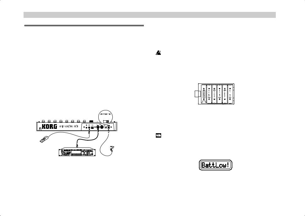
MIDI & AC adapter connection
 Before you make connections, you must turn off the power of all devices. Failure to do so may damage your speaker system or cause malfunctions.
1 |
Connect the AC adapter to the power connector of the |
|||||||||||||||||||||||||||||||
|
microKONTROL, and plug the adaptor into an AC outlet. |
|||||||||||||||||||||||||||||||
|
You don’t need the AC adapter if the microKONTROL is running on |
|||||||||||||||||||||||||||||||
|
batteries. |
|||||||||||||||||||||||||||||||
2 |
Use a MIDI cable to connect the microKONTROL to your external |
|||||||||||||||||||||||||||||||
|
device. If you will be using a pedal, connect it to the PEDAL jack. |
|||||||||||||||||||||||||||||||
|
|
|
|
|
|
|
|
|
|
|
|
|
|
|
|
|
|
|
|
|
|
|
|
|
|
|
|
|
|
|
|
|
|
|
|
|
|
|
|
|
|
|
|
|
|
|
|
|
|
|
|
|
|
|
|
|
|
|
|
|
|
|
|
|
|
|
|
|
|
|
|
|
|
|
|
|
|
|
|
|
|
|
|
|
|
|
|
|
|
|
|
|
|
|
|
|
|
|
|
|
|
|
|
|
|
|
|
|
|
|
|
|
|
|
|
|
|
|
|
|
|
|
|
|
|
|
|
|
|
|
|
|
|
|
|
|
|
|
|
|
|
|
|
|
|
|
|
|
|
|
|
|
|
|
|
|
|
|
|
|
|
|
|
|
|
|
|
|
|
|
|
|
|
|
|
|
|
|
|
|
|
|
|
|
|
|
|
|
|
|
|
|
|
|
|
|
|
|
|
|
|
|
|
|
|
|
|
|
|
|
|
|
|
|
|
|
|
|
|
|
|
|
|
|
|
|
|
|
|
|
|
|
|
|
|
|
|
|
|
|
|
|
|
|
|
|
|
|
|
|
|
|
|
|
|
|
|
|
|
|
|
|
|
|
|
|
|
|
|
|
|
|
|
|
|
|
|
|
|
|
|
|
|
|
|
|
|
|
|
|
|
|
|
|
|
|
|
|
|
|
|
|
|
|
|
|
|
|
|
|
|
|
|
|
|
|
|
|
|
|
|
|
|
|
|
|
|
|
|
|
|
|
|
|
|
|
|
|
|
|
|
|
|
|
|
|
|
|
|
|
|
|
|
|
|
|
|
|
|
|
|
|
|
Damper pedal |
AC adaptor |
|
or foot switch |
to an AC outlet |
|
MIDI sound module |
|
3 |
Set the microKONTROL’s power switch to the DC position to turn on |
|
|
the power. |
|
4 |
Turn on the power of the connected equipment. |
|
5 |
When you are ready to turn off the power, set the microKONTROL’s |
|
|
power switch to STANDBY. |
|
 Never turn off the power while you are saving settings (i.e., while the Write operation is occurring). Doing so may damage the internal data.
Using Batteries
The microKONTROL can run on battery power, without the AC adapter.
|
Batteries are not included. You will need to purchase them separately. |
||||||||||
|
If the AC adapter is connected, power will be taken from the AC |
||||||||||
|
|||||||||||
|
adapter instead of the batteries. |
||||||||||
1 |
Set the power switch to the STANDBY position, and open the cover of |
||||||||||
|
the battery compartment located on the bottom of the case. |
||||||||||
|
|
|
|
|
|
|
|
|
|
|
|
|
|
|
|
|
|
|
|
|
|
|
|
|
|
|
|
|
|
|
|
|
|
|
|
2 |
Insert six AA alkaline batteries (sold separately). Be sure to observe the |
|
correct orientation for each battery. |
3 |
Close the battery cover. |
To turn on the microKONTROL when using batteries, set the power switch to the DC position.
Battery empty indication
When the batteries run low, the main display will indicate “BattLow!”
If the “BattLow!” warning appears, you can continue using the microKONTROL for a certain length of time, but you will be unable to save assignment settings. If you need to save your settings, connect the AC adapter and do so. We recommend that you then replace the batteries as soon as possible, or continue using the AC adapter.
12
 When connecting the AC adapter while running on batteries, you must first connect the AC adapter to an electrical outlet, and then insert the plug into the microKONTROL’s power connector.
 If the batteries become unusable, take them out of the microKONTROL immediately. Leaving dead batteries installed may cause malfunctions (such as battery leakage). You should also remove the batteries if you will not be using the microKONTROL for an extended period.
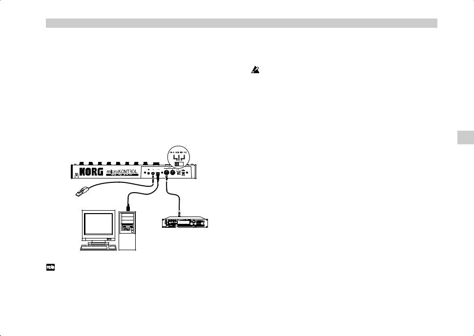
USB connection
1 Use a USB cable to connect the microKONTROL to the USB connector of your computer. You can leave your computer turned on when you make USB connections. If you will be using a pedal, connect it to the PEDAL jack.
Damper pedal USB cable MIDI cable or foot switch 
MIDI sound module
Computer
The microKONTROL can also be used as a USB-MIDI interface. You can connect a MIDI sound module or other MIDI device to the MIDI OUT connector, and send messages to it from your computer.
|
Introduction–Making connections and turning the power on |
2 |
Set the microKONTROL’s power switch to USB to turn on the power. |
|
When using a USB connection, the power is supplied from the |
|
connected computer (this is referred to as “bus power”). |
|
The same applies if you are using a self-powered USB hub. |
|
You won’t usually need to use the AC adapter if you are using a USB |
|
connection. However if your computer does not supply a large amount |
|
of power via USB, or if you have connected several bus-powered |
|
devices to a USB hub, the power supplied via USB may be insufficient. |
|
(If this occurs, the main display will indicate “LowPower.”) |
|
In such cases, use the AC adapter or batteries, and set the power switch |
|
to DC. |
3 |
When you are ready to turn off the power, set the power switch to |
|
STANDBY. |
 Never turn off the power while you are saving settings (i.e., while the Write operation is occurring). Doing so may damage the internal data.
 When the microKONTROL is being used as a USB MIDI interface, its MIDI OUT will transmit the data received via USB. MIDI messages transmitted by the encoders and other controllers of the microKONTROL itself will not be transmitted from the MIDI OUT connector ( p.37).
Making connections and turning the power on
13

Operation–About the microKONTROL’s modes
Operation
About the microKONTROL’s modes
The microKONTROL has four modes: Play, Setting, Message, and Scene.
1. Play mode
In this mode you can use the keyboard, pads, sliders, encoders, and other controllers to play and control connected MIDI sound modules or soft synthesizers and DAW programs running on your computer.
The assignments for each controller (“scene parameters”) can be recalled as a “scene” in Scene mode, or specified in Setting mode.
2. Setting mode
In this mode you can set both the scene parameters (assignments for each controller) and the global parameters (settings that apply to the entire microKONTROL).
Scene parameters include the MIDI messages assigned to each controller, and the MIDI channel and USB-MIDI port on which the assigned messages are transmitted. Set these parameters as appropriate for the connected MIDI sound module, or for the soft synthesizer or DAW program you are using on your computer.
The scene parameters you set can be stored in the microKONTROL’s internal memory in Scene mode. The stored settings are called a “scene.”
Global parameters include the keyboard velocity curve, display backlight, and global MIDI channel.
Global parameters will be saved automatically in internal memory when you press the [ENTER] key to return from Setting mode to Play mode.
3. Message mode
In this mode you can transmit various MIDI messages that are assigned to the pads.
Some pads transmit a MIDI message in response to a single operation, while others allow you to specify the MIDI message and MIDI channel before transmission.
4. Scene mode
In Scene mode you can do the following things.
•Choose a scene from user memory.
•Save the scene parameters you made in Setting mode as a “scene” in user memory.
•Write the preset scenes into user memory, restoring the factory settings.
•View the current values of the encoders and sliders in the sub-displays.
•Transmit or receive dumps of internal scenes or global parameters.
14
Quick Start
1. Turning on the power
Connect the microKONTROL to your computer, and turn on the power. ( p.12)
The main display shows the name of the currently selected scene.
Start up the software that you want to operate from the microKONTROL, and make the appropriate USB and MIDI settings in your software. For details on USB and MIDI settings, refer to the owner’s manuals for your software and computer.
2. Selecting a scene
The microKONTROL lets you assign parameters to each of its controllers (e.g., encoders and sliders) in order to control your DAW or softsynth in the most effective way. These settings are collectively called a “scene.”
The microKONTROL contains twelve preset scenes. Refer to the scene list in the included CD-ROM and select the most suitable scene for controlling your software. The included CD-ROM contains numerous scenes designed for specific software, in addition to the twelve factory-set internal scenes.
As an example, here’s how to select scene 2.
2
1
Operation–Quick Start
Step 1. Press the [SCENE] key. While you hold down this key, the main display will indicate “ScenePd?”; all of the pads 1 through 12 which contain a scene will light, and the pad of the currently selected scene will blink. ( p.52 “Scene mode”)
Step 2. The scene number is shown in the frame at the upper right of each pad. Hold down the [SCENE] key and press the pad marked “2”.
The main display will change to the name of scene 2, and the scene will change.
When you release the pad and the [SCENE] key you will return to Play mode.
At this point, you can use the keyboard and controller settings in the new Scene to control the software on your computer. ( p.19 “Play mode”)
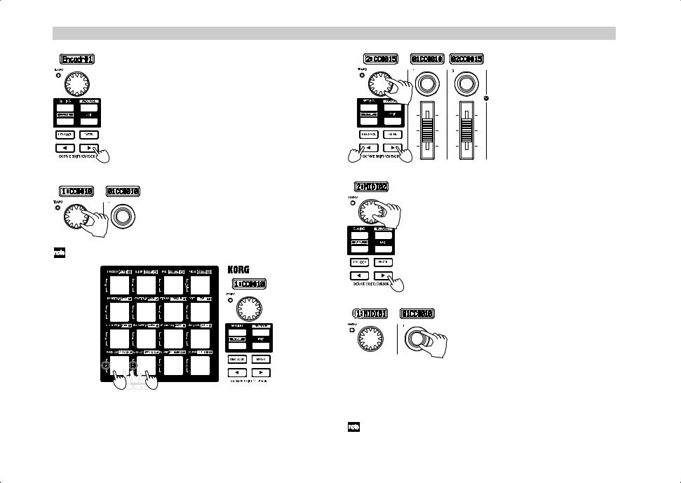
3. Making controller assignments
You can assign the pads, sliders, encoders, joystick, and pedals to a wide variety of MIDI messages.
As an example, here’s how to assign encoder 1 to MIDI Control Change #10 on MIDI channel 1, and assign encoder 2 to MIDI Control Change #15 on MIDI channel 2.
2
1
Step 1. Press the [SETTING] key. While you hold down this key, the main display indicates “MenuPad?”. ( p.24)
Step 2. Continue holding down the [SETTING] key and press the pad that is marked with the type of controller you want to assign.
The main display will indicate “Encodr#1”. Release the pad and key, and you will be in the Encoder Assign page. ( p.25)
Quick Start
15
Operation–Quick Start
The OCTAVE SHIFT/CURSOR [√] key will light red, and the [®] key will light green. Green indicates that further pages exist in that direction, and red indicates that there are no further pages in that direction.
Step 3. Use the [VALUE] dial to select the number of the encoder that you want to assign. Since we want to specify the assignment of encoder 1, make sure that the main display indicates “Encodr#1” and then press the OCTAVE SHIFT/CURSOR [®] key to move to the MIDI message selection page.
|
3 |
|
Step 4. The main display will show the MIDI |
|
message that is currently assigned to encoder |
|
1. Use the [VALUE] dial to select the MIDI |
4 |
message that you want to assign. |
The contents of the sub-display above encoder |
|
|
1 will also change. |
Alternatively, you can use the pads to input the control change number.
6, 8
5 |
7 |
10
9
Steps 5-8. Next, press the OCTAVE SHIFT/CURSOR [√] key to return to the page where you select the encoder to assign, select “Encodr#2” as the encoder number, and assign the desired MIDI message in the same way.
Notice that the sub-display above encoder 2 also changes.
Step 9. Press the OCTAVE SHIFT/CURSOR [®] key. The MIDI channel setting page will appear.
Since we just made an assignment for encoder 2, here we will specify the MIDI channel for encoder 2.
Step 10. Use the [VALUE] dial to select the desired channel.
Next we’ll specify the MIDI channel for encoder 1. We are back in the page where you select the encoder to assign, but you can also make the setting by directly
11 operating the controller you want to assign.
Step 11. Rotate encoder 1, and notice that both the main display and the encoder 1 display change.
You can use also this method in the MIDI message select page to quickly edit the assignments. You can also change the assignments for two or more encoders at once while watching the sub-displays.
You can use the same method to make assignments for sliders as well.
16
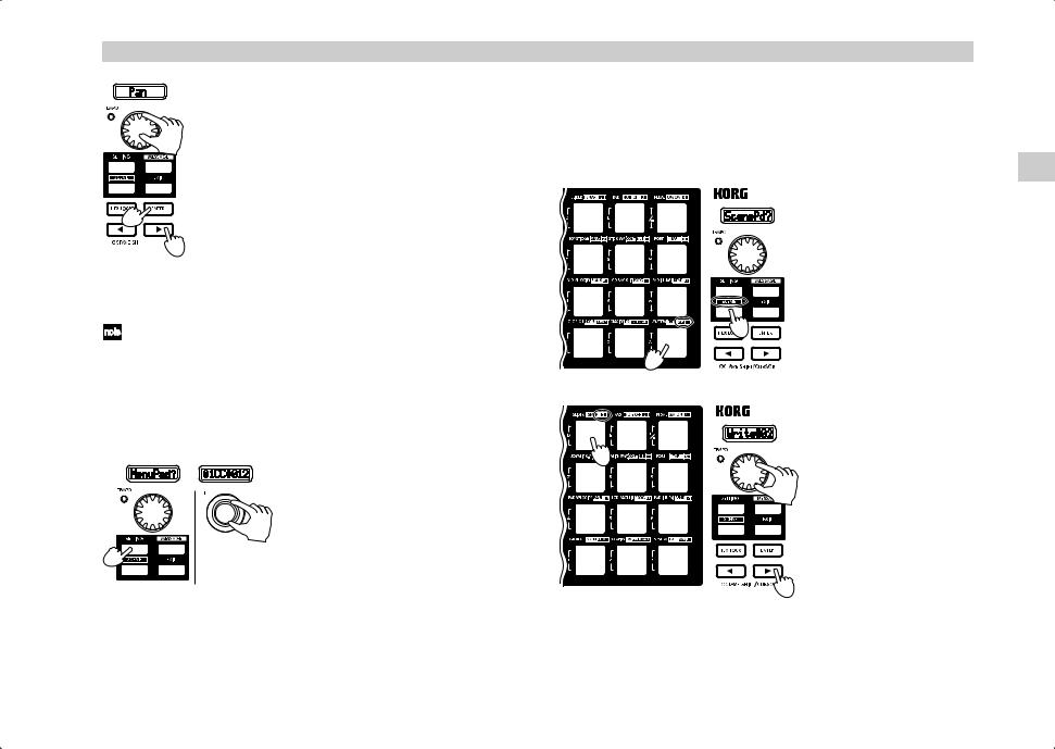
13
14


 12
12
Step 12. Press the OCTAVE SHIFT/CURSOR [®] key. The name select page will appear.
Since this is the last page of the encoder assignments, the OCTAVE SHIFT/CURSOR [®] key will light red, and the [ENTER] key will blink.
Step 13. Use the [VALUE] knob to select a name. For a list of the available names, refer to “Parameter Name (Encoder/Slider)” on the separate leaflet. Turn encoder 2 to choose a name for encoder 2.
Step 14. When you have made your selection, press the [ENTER] key to finalize the setting.You will then return to Play mode.
If you press the [ENTER] key in one of the preceding pages, the settings will be updated to the assignments you made up to that point.
If you assign an RPN or NRPN message, the page structure will be different. ( p.26)
Go ahead and make settings for other controllers as well, to create your scene. (For more about assigning other controllers, p.24 “Setting mode”)
Quick Assign
If you just want to set the control change number for an encoder or slider, here’s a simpler way to make the assignment.
Hold down the [SETTINGS] key and operate the encoder or slider you want to assign. The sub-display will change to show the MIDI message you select. When you release the [SETTING] key, the assignment will be updated and you will return to Play mode.
Operation–Quick Start
4. Saving a scene
If you don’t save your edited controller assignments, your changes will be lost when you select a different scene or turn off the power. Here’s how to save your controller assignments in a new scene so you won’t have to recreate them later.
You use Scene mode to save scenes. ( p.54)
|
Steps 1-2. Hold down the |
|
[SCENE] key and press the |
|
pad marked WRITE. |
|
You will enter the WRITE |
|
page. |
|
In this example, let’s save |
|
your assignments to scene 2. |
1 |
|
2 |
|
|
Step 3. Either press the pad in |
|
which you want to store the |
|
scene, or use the [VALUE] |
3 |
dial to select the scene |
|
number. |
3 |
Step 4. After you have made |
|
your selection, press the |
OCTAVE SHIFT/CURSOR [®] key to move to the next page.
4
Quick Start
17
 Loading...