


 Loading...
Excel 10
W7750A,B,C CONSTANT VOLUME AHU CONTROLLER
SYSTEM ENGINEERING |
|
|
Contents |
Introduction .................................................................................................................................. |
6 |
Description of Devices.......................................................................................... |
6 |
Control Application ............................................................................................... |
7 |
Control Provided................................................................................................... |
7 |
Products Covered................................................................................................. |
8 |
Organization of Manual ........................................................................................ |
8 |
Applicable Literature............................................................................................. |
8 |
Product Names..................................................................................................... |
9 |
Agency Listings .................................................................................................... |
9 |
Abbreviations and Definitions............................................................................... |
10 |
Construction ......................................................................................................... |
11 |
Controllers ...................................................................................................... |
11 |
PERFORMANCE SPECIFICATIONS ......................................................... |
13 |
LONMARK® Functional Profile ..................................................................... |
17 |
Inputs/Outputs: ............................................................................................... |
18 |
ANALOG INPUTS:...................................................................................... |
18 |
DIGITAL INPUTS: ....................................................................................... |
19 |
TRIAC OUTPUTS ON THE (W7750B,C MODELS ONLY):........................ |
19 |
DIGITAL OUTPUTS: ................................................................................... |
19 |
Wall Modules .................................................................................................. |
20 |
Duct Sensor .................................................................................................... |
20 |
Configurations ...................................................................................................... |
22 |
General ........................................................................................................... |
22 |
Allowable Heating and Cooling Equipment Configurations ............................ |
24 |
STAGED HEATING/COOLING CONTROL ................................................ |
24 |
MODULATING HEATING/COOLING CONTROL ....................................... |
24 |
HEAT PUMP CONTROL............................................................................. |
24 |
ECONOMIZER CONTROL ......................................................................... |
25 |
PNEUMATIC ACTUATOR CONTROL ........................................................ |
25 |
MIXED-OUTPUT-TYPE CONTROL ........................................................... |
26 |
Occupancy Sensor ......................................................................................... |
26 |
Window Open/Closed Digital Input ................................................................. |
26 |
Wall Module Options ....................................................................................... |
26 |
Dirty Filter Monitor .......................................................................................... |
27 |
Indoor Air Quality (IAQ) Override ................................................................... |
27 |
Smoke Control ................................................................................................ |
27 |
Freeze Stat ..................................................................................................... |
27 |
Modes of Operation .............................................................................................. |
27 |
Application Steps .................................................................................................................................. |
29 |
Overview .............................................................................................................. |
29 |
Step 1. Plan the System....................................................................................... |
29 |
Step 2. Determine Other Bus Devices Required .................................................. |
29 |
Step 3. Lay Out Communications and Power Wiring ........................................... |
30 |
LONWORKS® Bus La yout ................................................................................ |
30 |
Power Wiring .................................................................................................. |
32 |
POWER BUDGET CALCULATION EXAMPLE .......................................... |
32 |
LINE LOSS ................................................................................................. |
33 |
Step 4. Prepare Wiring Diagrams......................................................................... |
35 |
® U.S. Re gistered Trademark |
|
Copyright © 2000 Hone ywell Inc. • All Rights Reserved |
74-2958- 1 |

EXCEL 10 W7750A,B,C CONSTANT VOLUME AHU CONTROLLER
General Considerations .................................................................................. |
35 |
W7750 Controllers .......................................................................................... |
36 |
FACTORY DEFAULT DIGITAL OUTPUTS: ................................................ |
37 |
LONWORKS® Bus Termination Module ........................................................... |
43 |
Step 5. Order Equipment ..................................................................................... |
45 |
Step 6. Configure Controllers............................................................................... |
48 |
Step 7. Troubleshooting ....................................................................................... |
48 |
Troubleshooting Excel 10 Controllers and Wall Modules ............................... |
48 |
Temperature Sensor and Setpoint Potentiometer Resistance Ranges .......... |
49 |
Alarms ............................................................................................................ |
49 |
Broadcasting the Service Message ................................................................ |
50 |
W7750 Controller Status LED ........................................................................ |
50 |
T7770C,D Wall Module Bypass Pushbutton and Override LED ..................... |
51 |
T7560A,B Digital Wall Module Bypass Pushbutton and LCD Display Occupancy |
|
Symbols .......................................................................................................... |
51 |
Appendices .................................................................................................................................. |
51 |
Appendix A. Using E-Vision to Commission a W7750 Controller......................... |
51 |
Sensor Calibration .......................................................................................... |
51 |
Setting the Pid Parameters ............................................................................ |
51 |
Appendix B. Sequences of Operation. ................................................................. |
52 |
Common Operations ...................................................................................... |
53 |
Room Temperature Sensor (RmTemp)....................................................... |
54 |
Remote Setpoint (RmtStptPot) ................................................................... |
55 |
Setpoint Limits (LoSetptLim and HiSetptLim)............................................. |
55 |
Bypass Mode (StatusOvrd and StatusLed) ................................................ |
55 |
BYPASSTIME............................................................................................. |
55 |
OverrideType .............................................................................................. |
55 |
OverridePriority........................................................................................... |
55 |
Cycles per Hour (ubHeatCph and ubCoolCph) .......................................... |
55 |
T7770C,D or T7560A,B Wall Module Bypass Pushbutton Operation......... |
55 |
Standby Mode (StatusOcySen) .................................................................. |
56 |
Continuous Unoccupied Mode ................................................................... |
56 |
Occupancy Mode and Manual Override Arbitration.................................... |
56 |
Time Clock (Occ_Time_Clock) ................................................................... |
57 |
Schedule Master (Sched_Master) .............................................................. |
57 |
Setpoint Ramping ....................................................................................... |
57 |
Recovery Ramping for Heat Pump Systems .............................................. |
57 |
Fan Operation............................................................................................. |
58 |
Window Sensor (StatusWndw)................................................................... |
58 |
Smoke Control............................................................................................ |
58 |
Demand Limit Control (DLC) ...................................................................... |
58 |
Dirty Filter Monitor ...................................................................................... |
59 |
Start-Up ...................................................................................................... |
59 |
Temperature Control Operations .................................................................... |
59 |
Staged Cooling Control .............................................................................. |
60 |
Staged Heating Control .............................................................................. |
60 |
Cascade Control of Modulating Cooling/Heating........................................ |
61 |
Series 60 Modulating Control ..................................................................... |
61 |
Pulse Width Modulating (PWM) Control ..................................................... |
61 |
Outdoor Air Lockout of Heating/Cooling ..................................................... |
61 |
Economizer Damper Control ...................................................................... |
61 |
Indoor Air Quality (IAQ) Override ............................................................... |
62 |
Freeze Stat ................................................................................................. |
62 |
Discharge Air Low Limit Control ................................................................. |
62 |
Economizer Enable/Disable Control........................................................... |
62 |
Appendix C. Complete List of Excel 10 W7750 Controller User Addresses. ....... |
62 |
User Address Indexes (all in alphabetical order) ............................................ |
63 |
Mappable User Addresses and Table Number ............................................... |
64 |
Failure Detect User Addresses and Table Number ........................................ |
65 |
Appendix D. Q7750A Excel 10 Zone Manager Point Estimating Guide............... |
109 |
Approximate Memory Size Estimating Procedure. ......................................... |
109 |
Appendix E. Sensor Data for Calibration. ............................................................ |
110 |
Resistance Sensors. ...................................................................................... |
110 |
Voltage/Current Sensors. ............................................................................... |
112 |
72-2958— 1 |
2 |
EXCEL 10 W7750A,B,C CONSTANT VOLUME AHU CONTROLLER |
|
List of Figures |
|
Fig. 1. Typical system overview. ................................................................................................................................................ |
6 |
Fig. 2. Typical W7750 control application. ................................................................................................................................. |
7 |
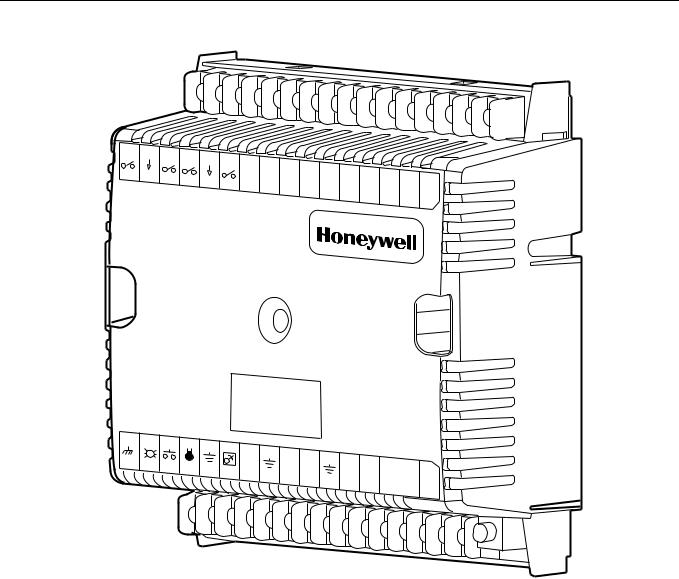
Fig. 3. Excel 10 W7750A Constant Volume AHU Controller. ..................................................................................................... |
12 |
Fig. 4. W7750A construction in in. (mm). ................................................................................................................................... |
13 |
Fig. 5. Excel 10 W7750B Constant Volume AHU Controller. ..................................................................................................... |
14 |
Fig. 6. Excel 10 W7750C Constant Volume AHU Controller. .................................................................................................... |
15 |
Fig. 7. W7750B,C construction in in. (mm). W7750C (shown) has three 4 to 20 mA analog outputs.) ..................................... |
16 |
Fig. 8. DIN rail adapters. ............................................................................................................................................................ |
17 |
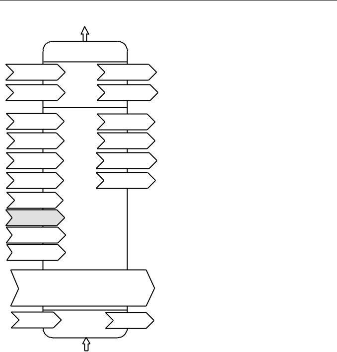
Fig. 9. Functional profile of LONMARK® RTU object details (variables not implemented in Excel 10 CVAHU |
|
are greyed)........................................................................................................................................................................ |
18 |
Fig. 10. T7770A,B,C,D construction in in. (mm). ....................................................................................................................... |
20 |
Fig. 11. T7560A,B construction in in. (mm). ............................................................................................................................... |
21 |
Fig. 12. C7770A construction in in. (mm). .................................................................................................................................. |
21 |
Fig. 13. Fan with two stages of heating and two stages |
|
of cooling........................................................................................................................................................................... |
24 |
Fig. 14. Fan, modulating heating and modulating cooling. ......................................................................................................... |
24 |
Fig. 15. Heat pump with two compressors and auxiliary heat stage(s)....................................................................................... |
25 |
Fig. 16. Economizer control. ...................................................................................................................................................... |
25 |
Fig. 17. Modulating heat with pneumatic valve actuator............................................................................................................. |
26 |
Fig. 18. Connecting the portable operator terminal |
|
to the LONWORKS® Bus..................................................................................................................................................... |
29 |
Fig. 19. Wiring layout for one doubly terminated daisy-chain LONWORKS® Bus segment. ........................................................ |
31 |
Fig. 20. Wiring layout for two singly terminated LONWORKS® Bus segments............................................................................. |
32 |
Fig. 21. NEMA class 2 transformer voltage output limits. ........................................................................................................... |
34 |
Fig. 22. Power wiring details for one Excel 10 per transformer. ................................................................................................. |
34 |
Fig. 23. Power wiring details for two or more Excel 10s per transformer. .................................................................................. |
34 |
Fig. 24. Transformer power wiring details for one Excel 10 used in UL 1995 equipment (U.S. only)......................................... |
35 |
Fig. 25. Attaching two or more wires at terminal blocks.............................................................................................................. |
36 |
Fig. 26. W7750B High-Side/Low-Side selectable switching and jumper location....................................................................... |
36 |
Fig. 27. Typical W7750A Controller AHU application wiring diagram. (For more information on note 2, |
|
refer to Fig. 25.)................................................................................................................................................................ |
38 |
Fig. 28. Typical W7750A Controller with separate transformer application wiring diagram. |
|
(For more information on note 2, refer to Fig. 25.) ............................................................................................................ |
38 |
Fig. 29. W7750A Controller floating economizer damper wiring diagram. (For more information on note 2, refer to Fig. 25.)... |
39 |
Fig. 30. Typical W7750B Controller with staged heating and cooling wiring diagram. (For more information on note 2, refer to Fig. 25.) .................................................................................................................................................................................... 40 Fig. 31. W7750B Controller with floating heating, cooling and economizer wiring diagram. (For more information on note 2, refer
to Fig. 25.) ......................................................................................................................................................................... |
40 |
Fig. 32. W7750B,C Controller PWM damper actuator wiring diagram. (For more information on note 2, refer to |
|
Fig. 25.) ............................................................................................................................................................................. |
41 |
Fig. 33. W7750B,C wiring diagram with 4 to 20 mA enthalpy sensors and digital inputs. (For more information on note 2, refer to
Fig. 25.) ............................................................................................................................................................................. |
41 |
Fig. 34. W7750B,C wiring diagram with C7600C 4 to 20 mA solid state humidity sensor. (For more information on note 2, refer to
Fig. 25.) ............................................................................................................................................................................. |
42 |
Fig. 35. W7750C Controller with 4-to-20 mA heating, cooling and economizer wiring diagram. AOs must use terminals 16, 17 or
18. The AOs can be set to be reverse acting. (For more information on note 2, refer to Fig. 25.).................................... |
42 |
|
Fig. 36. Pneumatic transducer to W7750B,C |
|
|
(B shown, see triangle note 4). ......................................................................................................................................... |
43 |
|
Fig. 37. RP7517,B pneumatic transducer to W7750C. ............................................................................................................... |
43 |
|
Fig. 38. Typical doubly terminated daisy-chain LONWORKS® Bus segment termination module wiring diagram. ..................... |
44 |
|
Fig. 39. LONWORKS® Bus termination wiring options. ............................................................................................................... |
45 |
|
Fig. 40. Temperature sensor resistance plots............................................................................................................................. |
49 |
|
Fig. 41. Location of the Service Pin Button................................................................................................................................. |
50 |
|
Fig. 42. LED location on W7750. ................................................................................................................................................ |
51 |
|
Fig. 43. The T7770C,D Wall Modules LED and Bypass pushbutton locations........................................................................... |
51 |
|
Fig. 44. |
The T7560A,B Digital Wall Module Bypass pushbutton location................................................................................... |
51 |
Fig. 45. |
LED and Bypass pushbutton operation. ....................................................................................................................... |
56 |
Fig. 46. |
Setpoint ramping parameters with ramp rate calculation............................................................................................... |
57 |
Fig. 47. |
Setpoint ramping parameters with setpoint calculation.................................................................................................. |
58 |
3 |
74-2958— 1 |

EXCEL 10 W7750A,B,C CONSTANT VOLUME AHU CONTROLLER |
|
|
Fig. 48. Setpoint ramping parameters with ramp rate calculation............................................................................................... |
58 |
|
Fig. 49. Schematic diagram for a typical W7750B Unit. ............................................................................................................. |
59 |
|
Fig. 50. Staged output control versus PID Error. ....................................................................................................................... |
60 |
|
Fig. 51. Point capacity estimate for Zone Manager. .................................................................................................................. |
109 |
|
Fig. 52. Graph of Sensor Resistance versus Temperature......................................................................................................... |
110 |
|
Fig. 53. Graph of Sensor Resistance versus Temperature......................................................................................................... |
110 |
|
Fig. 54. Graph of Sensor Resistance versus Temperature......................................................................................................... |
111 |
|
Fig. 55. Graph of Sensor Resistance versus Temperature......................................................................................................... |
111 |
|
Fig. 56. Graph of Sensor Resistance versus Temperature......................................................................................................... |
112 |
|
Fig. 57. Graph of Sensor Voltage versus Humidity..................................................................................................................... |
112 |
|
Fig. 58. C7600C output current vs. humidity............................................................................................................................... |
112 |
|
Fig. 59. Graph of Sensor Current versus Enthalpy (volts). ......................................................................................................... |
113 |
|
Fig. 60. Partial psychometric chart for a C7400A Solid State Enthalpy Sensor. ........................................................................ |
114 |
|
Fig. 61. |
C7400A Solid State Enthalpy Sensor output current vs. relative humidity. ................................................................... |
114 |
Fig. 62. |
Graph of Sensor Voltage versus CO2 concentration..................................................................................................... |
115 |
Fig. 63. |
Graph of Sensor Voltage versus input Voltage to A/D.................................................................................................. |
115 |
Fig. 64. |
Graph of Sensor Voltage (Vdc) versus Pressure (Inw).................................................................................................. |
116 |
74-2958— 1 |
4 |

EXCEL 10 W7750A,B,C CONSTANT VOLUME AHU CONTROLLER |
|
List of Tables |
|
Table 1. Agency Listing. ............................................................................................................................................................. |
9 |
Table 2. List of Differences in W7750A and W7750B,C Controllers........................................................................................... |
11 |
Table 3. Common Configuration Options Summary For W7750A,B,C Controllers..................................................................... |
22 |
Table 4. Configuration Options Summary For W7750A,B,C Controllers. ................................................................................... |
23 |
Table 5. Modes Of Operation For The Excel 10 W7750 Controller . .......................................................................................... |
27 |
Table 6. Application Steps. ......................................................................................................................................................... |
29 |
Table 7. LONWORKS® Bus Configuration Rules And Device Node Numbers. ............................................................................ |
30 |
Table 8. VA Ratings For Transformer Sizing. ............................................................................................................................. |
33 |
Table 9. Field Wiring Reference Table (Honeywell listed as AK#### or equivalent).................................................................. |
36 |
Table 10. W7750A Version I/O Description. ............................................................................................................................... |
37 |
Table 11. Excel 10 W7750 Controller Ordering Information. ...................................................................................................... |
46 |
Table 12. Excel 10 Alarms.......................................................................................................................................................... |
49 |
Table 14. Common Configuration Options Summary For W7750A,B,C Controllers................................................................... |
53 |
Table 15. Configuration Options Summary For W7750A,B,C Controllers. ................................................................................. |
54 |
Table 16. Bypass Pushbutton Operation. ................................................................................................................................... |
55 |
Table 17. Interstage Minimum Times.......................................................................................................................................... |
60 |
Table 18. Excel 10 W7750 Controller User |
|
Address Point Types................................................................................................................................................................... |
62 |
Table 20. Input/Output Points. .................................................................................................................................................... |
67 |
Table 21. Control Parameters..................................................................................................................................................... |
73 |
Table 22. Energy Management Points........................................................................................................................................ |
78 |
Table 23. Status Points............................................................................................................................................................... |
81 |
Table 24. Calibration Points........................................................................................................................................................ |
93 |
Table 25. Configuration Parameters. .......................................................................................................................................... |
94 |
Table 26. LONMARK® /Open System Points. ............................................................................................................................... |
97 |
Table 27. Direct Access And Special Points............................................................................................................................... |
106 |
Table 28. Data Share Points....................................................................................................................................................... |
108 |
Table 29. Sensor Resistance Versus Temperature.................................................................................................................... |
110 |
Table 30. Sensor Resistance Versus Temperature.................................................................................................................... |
110 |
Table 31. Sensor Resistance Versus Temperature.................................................................................................................... |
111 |
Table 32. Sensor Resistance Versus Temperature.................................................................................................................... |
111 |
Table 33. Sensor Resistance Versus Temperature.................................................................................................................... |
111 |
Table 34. Sensor Voltage Versus Humidity. ............................................................................................................................... |
112 |
Table 35. Sensor Voltage Versus Humidity. ............................................................................................................................... |
112 |
Table 36. Sensor Current Versus Enthalpy (volts)...................................................................................................................... |
113 |
Table 37. Sensor Voltage Versus CO2 Concentration. .............................................................................................................. |
115 |
Table 38. Sensor Voltage Versus Input Voltage To A/D............................................................................................................. |
115 |
Table 39. Sensor Voltage (Vdc) Versus Pressure (Inw). ............................................................................................................ |
116 |
5 |
74-2958— 1 |
EXCEL 10 W7750A,B,C CONSTANT VOLUME AHU CONTROLLER
INTRODUCTION
LONWORKS network (LONWORKS Bus) for communications, and conforms with the LONMARK HVAC Interoperability standard for Roof Top Unit Controllers (see Fig. 9).
Description of Devices
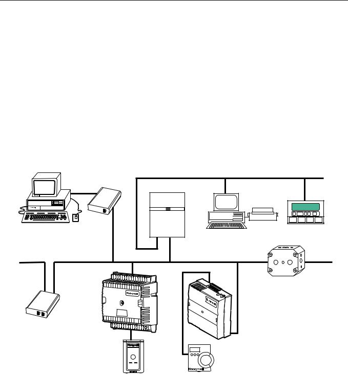
The W7750 is the Constant Volume Air Handling Unit (CVAHU) Controller in the Excel 10 product line family. The CVAHU is a LONMARK compliant device designed to control single zone and heat pump air handlers. W7750 systems control the space temperature in a given zone by regulating the heating and cooling equipment in the air handler that delivers air to that space. The W7750 air handler is typically an all-in-one constant air volume packaged unit, located on the roof of the building. In addition to standard heating and cooling control, the W7750 provides many options and advanced system features that allow state-of-the-art commercial building control. The W7750 Controller is capable of stand-alone operation; however, optimum functional benefits are achieved when the network communication capabilities are used. The W7750 utilizes the Echelon
The T7770 or T7560 direct-wired Wall Modules are used in conjunction with W7750 Controllers. The zone controlled by the W7750 Controller typically can use a T7770A through D or a T7560A,B Wall Module. Additional features available in T7770A through D models include analog setpoint input knob, override digital input pushbutton, override status LED and LONWORKS Bus network access jack. Additional features available in T7560A,B models include analog setpoint input knob, override digital input pushbutton, humidity sensor (T7650B model), override status LCD and digital display.
The Q7750A Excel 10 Zone Manager is a communications interface that allows devices on the LONWORKS Bus network to communicate with devices on the standard EXCEL 5000 System C-Bus. Fig. 1 shows an overview of a typical system layout. The Q7750A also provides some control and monitoring functions.
Q7752A |
|
|
|
|
|
|
|
|
|
|
C-BUS COMMUNICATION NETWORK |
|
|||||
LONWORKS BUS |
|
|
|
|
|
||||||||||||
|
|
|
|
|
|
||||||||||||
SERIAL |
|
|
|
|
|
|
|
|
|
|
|
|
|||||
ADAPTER |
|
|
|
|
|
|
|
|
|
|
|||||||
|
|
|
|
|
|
|
|
|
|
|
|
|
|
|
EXCEL 10 |
|
|
|
|
|
|
|
|
|
|
|
|
|
|
|
|
|
Q7750A |
|
|
PERSONAL COMPUTER TOOLS |
|
|
|
|
|
|
|
|
|
|
|
|
|
|
ZONE |
|
EXCEL 500 |
E-VISION |
|
|
|
|
|
|
|
|
|
|
|
|
|
|
MANAGER |
EXCEL BUILDING SUPERVISOR |
|
|
|
|
|
|
|
|
|
|
|
|
|
|
|
|
|||
CARE |
|
|
|
|
|
|
|
|
|
|
|
|
|
|
|
|
|
|
|
|
|
|
|
|
|
|
|
|
|
|
|
|
C-BUS TO LONWORKS BUS |
|
|
|
|
|
|
|
|
|
|
|
|
|
|
|
|
|
INTERFACE DEVICE |
Q7740A |
|
LONWORKS-BUS COMMUNICATIONS NETWORK |
|
|
|
|
|
|
|
|
|
|
|
|
|
|
2-WAY |
||
|
|
|
|
|
|
|
|
|
|
|
|
LONWORKS BUS COMMUNICATIONS NETWORK |
REPEATER |
||||
31 |
30 |
29 |
28 |
27 |
26 |
|
|
|
|
|
|
|
|
|
|
|
|
|
|
|
|
25 |
24 |
23 |
22 |
21 |
20 |
19 |
|
|
|
|
|
||
|
|
|
|
|
|
|
|
18 |
17 |
16 |
|
|
|||||
|
EXCEL 10 |
|
|
|
|
|
|
|
|
|
|
|
|
|
|
EXCEL 10 W7751F |
|
W7750B |
|
|
|
|
|
|
|
|
|
|
|
|
|
|
|
|
CVAHU |
|
|
|
|
|
|
|
|
|
|
|
|
|
|
PANEL PLENUM |
|
CONTROLLER |
|
|
|
|
|
|
|
|
|
|
|
|
|
|
MOUNT VERSION |
|
|
|
|
|
|
|
|
|
|
|
|
|
|
|
|
VARIABLE AIR VOLUME |
Q7751A |
1 |
|
|
|
|
|
|
|
|
10 |
11 |
12 |
13 |
14 |
15 |
CONTROLLER |
|
2 |
3 |
4 |
5 |
6 |
|
|
|
|
|
|
|
|
|
|
|
|
|
7 |
8 |
9 |
|
|
|
|
|
|
|
|||||
FTT |
|
|
|
|
|
|
|
|
|
|
|
|
|
|
|
|
LONWORKS BUS |
|
|
|
|
|
|
|
|
|
|
|
|
|
|
|
|
ROUTER |
|
|
|
|
|
|
|
|
|
|
|
|
|
|
|
|
|
EXCEL 10 T7770 |
|
|
|
|
|
|
|
|
EXCEL 10 T7560A, B |
||||||
|
WALL MODULE |
|
|
|
|
|
|
|
|
WALL MODULE |
||||||
M17487
Fig. 1. Typical system overview.
74-2958— 1 |
6 |

EXCEL 10 W7750A,B,C CONSTANT VOLUME AHU CONTROLLER
Control Application
W7750 systems in commercial buildings typically incorporate a packaged air handler system that delivers a constant volume of air at preconditioned temperatures to the zone being served. Each zone is usually serviced by a separate AHU; however, sometimes two or more AHUs service the same zone. Note that the W7750 is not designed to control Variable Air Volume (VAV) air handlers or Multi-Zone air handlers, where one air handler simultaneously controls the space temperature in many zones.
OA TEMP
The W7750 can control staged or modulating heating and cooling coils, mixed air economizer dampers, and the system fan. Control of heat pump units, where the compressor(s) is used for both cooling and heating, is also provided. The zone the W7750 services can use a T7770 or T7650 for space temperature sensing and an LONWORKS Bus network access for users. Fig. 2 shows a typical W7750 control application.
|
COOL |
HEAT |
FILTER |
COIL |
COIL |
|
FAN |
|
OUTDOOR |
|
|
AIR |
- |
+ |
|
||
M |
|
|
EXCEL 10
W7750
CVAHU
DA TEMP
RA TEMP |
ROOF |
CEILING
OCCUPANCY
SENSOR
RETURN |
T7770 OR T7560A,B |
DISCHARGE |
M17488 |
|
AIR |
AIR |
|||
|
WINDOW CONTACT
Fig. 2. Typical W7750 control application.
Control Provided
The W7750 Controller is designed to control a single air handler to maintain the units space temperature at the current setpoint. Heating and cooling control is provided for either staged or modulating equipment. Up to four stages of mechanical cooling and up to four stages of heating are allowed. Modulating outputs can be either floating type such as a Series 60 control, or Pulse Width Modulated (PWM W7750B,C only) control.
The economizer dampers can be controlled directly with floating or PWM outputs, or indirectly using a digital output as an enable/disable signal to a packaged economizer controller. The economizer enable function, which decides when to allow outdoor air to be used for free cooling, can be configured to
one of ten strategies based on the inputs. For more details, see Appendix B— Sequences of Operation. When the economizer position is controlled from the W7750, the minimum position setting (for ventilation requirements) can be adjusted based on indoor air quality (IAQ) needs in the space. IAQ monitoring is provided through either a CO2 sensor or a digital input from a space-mounted IAQ limit switch.
For heat pump configurations, up to four compressors can be controlled, along with up to four stages of auxiliary heat, and a heat/cool change over valve. Including the supply fan, the combination of these items may not exceed eight outputs if a W7750B,C is used, or six outputs for a W7750A. (The eight outputs on the W7750C consist of five digital and three analog outputs.)
7 |
74-2958— 1 |

EXCEL 10 W7750A,B,C CONSTANT VOLUME AHU CONTROLLER
Like the W7751 VAV Box Controller, the W7750 Controller can |
Form No. |
Title |
||
monitor a space-mounted occupancy sensor, and a door/ |
|
|
||
window contact. These inputs affect the operational mode of |
74-2956 |
Excel 10 W7750A,B,C Controller Specification |
||
the controller (see Table 5 for a list of all possible modes of |
|
Data |
||
operation). |
74-2697 |
Excel 10 T7770A,B,C,D,E,F,G Wall Module |
||
The W7750 Controller allows other controllers in the system to |
||||
|
Specification Data |
|||
use the W7750s physical inputs and outputs. A digital input |
|
|
||
and an analog input can be configured to read switch states |
74-3097 |
T7560A,B Digital Wall Module Specification |
||
and voltage sensor values, respectively, and send them out |
|
Data |
||
over the LONWORKS Bus network. The Q7750A Zone |
|
|
||
Manager can use these values in custom control strategies. |
74-2950 |
Excel 10 Q7750A, Zone Manager Specification |
||
Additionally, two of the W7750 digital outputs are available for |
|
Data |
||
control program use. These outputs only respond to signals |
|
|
||
sent over the network, and are not controlled by the W7750 |
74-2952 |
Excel 10 Q7751A,B Router Specification Data |
||
internal control algorithms. |
74-2954 |
Excel 10 Q7752A Serial Interface Specification |
||
|
|
|||
Products Covered |
|
Data |
||
|
|
|||
This System Engineering Guide describes how to apply the |
74-3067 |
Q7752B PCMCIA LONWORKS PCC-10 Card |
||
Excel 10 family of W7750 CVAHU Controllers and related |
|
Specification Data |
||
accessories to typical applications. The specific devices |
74-2858 |
Excel 10 Q7740A,B FTT Repeaters |
||
covered include: |
||||
• |
W7750A,B,C Controllers. |
|
Specification Data |
|
74-2951 |
Excel 10 Q7750A Zone Manager Checkout |
|||
• T7770A through D Wall Modules. |
||||
• |
T7560A,B Wall Modules. |
|
and Test Manual |
|
• Q7750A Excel 10 Zone Manager. |
95-7521 |
Excel 10 W7750A,B,C Controller Installation |
||
• Q7751A,B Router (FTT to FTT and TPT to FTT). |
||||
• |
Q7752A Serial Interface. |
|
Instructions |
|
• Q7740A,B Repeaters (2-way and 4-way). |
95-7538 |
Excel 10 T7770A,B,C,D,E,F,G Wall Module |
||
• 209541B FTT Termination Module. |
||||
|
|
|
Installation Instructions |
|
Organization of Manual |
95-7620 |
T7560A,B Digital Wall Module Installation |
||
This manual is divided into three basic parts: the Introduction, |
|
Instructions |
||
the Application Steps, and the Appendices that provide |
95-7509 |
Excel 10 Q7750A Zone Manager Installation |
||
supporting information. The Introduction and Application |
||||
Steps 1 through 5 provide the information needed to make |
|
Instructions |
||
accurate material ordering decisions. Application Step 6 and |
95-7510 |
Excel 10 Q7751A,B Router Installation |
||
the Appendices include configuration engineering that can be |
||||
started using Excel E-Vision PC Software after the devices |
|
Instructions |
||
and accessories are ordered. Application Step 7 is |
95-7511 |
Excel 10 Q7752A Serial Interface Installation |
||
troubleshooting. |
||||
The organization of the manual assumes a project is being |
|
Instructions |
||
95-7613 |
Q7752B PCMCIA LONWORKS PCC-10 Card |
|||
engineered from start to finish. If an operator is adding to, or is |
||||
changing an existing system, the Table of Contents can |
|
Installation Instructions |
||
provide the relevant information. |
|
|
||
Applicable Literature
95-7555 Excel 10 Q7740A,B FTT Repeaters Installation
Instructions
The following list of documents contains information related to |
95-7554 |
Excel 10 209541B Termination Module |
the Excel 10 W7750 CVAHU Controller and the EXCEL 5000 |
|
Installation Instructions |
OPEN SYSTEM in general. |
74-2588 |
Excel E-Vision User’s Guide |
|
||
|
74-5587 |
CARE User’s Manual |
|
74-1392 |
CARE Excel 10 Zone Manager User’s Guide |
|
74-5577 |
CARE Icon Guide |
|
74-2039 |
XBS User’s Manual |
|
74-5018 |
XBS Application Guide |
74-2958— 1 |
8 |

EXCEL 10 W7750A,B,C CONSTANT VOLUME AHU CONTROLLER
Product Names
The W7750 Controller is available in three models:
•W7750A Constant Volume AHU Controller - W7750A Version.
•W7750B Constant Volume AHU Controller - W7750B Version.
•W7750C Constant Volume AHU Controller - W7750C
Version.
The T7770 Wall Module is available in four models. The T7770 Wall Modules will work with all Excel 5000 and Excel 10 Controllers (except the W7751A,C,E,G):
•T7770A1xxx Wall Module with nonlinearized 20 Kohm NTC sensor only.
•T7770A2xxx Wall Module with nonlinearized 20 Kohm NTC sensor and LONWORKS Bus jack.
•T7770B1xxx Wall Module with nonlinearized 20 Kohm NTC sensor, 10 Kohm setpoint, and LONWORKS Bus jack.
•T7770C1xxx Wall Module with nonlinearized 20 Kohm NTC sensor, 10 Kohm setpoint, bypass button and LED, and LONWORKS Bus jack.
•T7770D1xxx Wall Module with nonlinearized 20 Kohm NTC sensor, bypass button and LED, and LONWORKS Bus jack.
NOTE: The T7770B,C Models are available with a absolute 55 to 85°F (10 to 85°C) or a relative scale plate adjustable in E-Vision to ± 18°F (± 5°C).
The T7560A,B Wall Module is available in two models:
•T7560A Wall Module displays and provides space temperature, setpoint, Occ/Unocc override, override status LCD and digital display.
•T7560B Wall Module displays and provides space temperature, humidity sensor, setpoint, Occ/Unocc override, override status LCD and digital display.
Other products:
•Q7750A Excel 10 Zone Manager.
•Q7751A,B Bus Router.
•Q7752A Serial Adapter.
•Q7740A,B FTT Repeaters.
•209541B FTT Termination Module.
Refer to Table 11 in Application Step 5. Order Equipment for a complete listing of all available part numbers.
NOTE: The Q7750A Zone Manager is referred to as (E-Link) in internal software and CARE.
Agency Listings
Table 1 provides information on agency listings for Excel 10 products. Be sure to always follow Local Electrical Codes.
|
|
Table 1. Agency Listing. |
|
|
|
|
|
Device |
Agency |
|
Comments |
|
|
|
|
W7750A,B,C Controllers |
UL |
Tested and listed under UL916 (file number E87741). The CVAHU W7750A,B,C |
|
|
|
Controllers are UL94-5V listed and suitable for plenum mounting. |
|
|
|
|
|
|
cUL |
Listed (E87741). |
|
|
|
|
|
|
CE |
General Immunity per European Consortium Standards EN50081-1 (CISPR 22, Class B) |
|
|
|
and EN 50082-1:1992 (based on Residential, Commercial, and Light Industrial). |
|
|
|
EN 61000-4-2: |
IEC 1000-4-2 (IEC 801-2) Electromagnetic Discharge. |
|
|
EN 50140, EN 50204: IEC 1000-4-3 (IEC 801-3) Radiated Electromagnetic Field. |
|
|
|
EN 61000-4-4: |
IEC 1000-4-4 (IEC 801-4) |
|
|
|
Electrical Fast Transient (Burst). Radiated Emissions and |
|
|
|
Conducted Emissions: |
|
|
EN 55022: |
1987 Class B. |
|
|
CISPR-22: |
1985. |
|
|
|
|
|
FCC |
Complies with requirements in FCC Part 15 rules for a Class B Computing Device. |
|
|
|
Operation in a residential area can cause interference to radio or TV reception and require |
|
|
|
the operator to take steps necessary to correct the interference. |
|
|
|
|
|
T7770A,B,C,D and |
UL |
(Not applicable.) |
|
T7560A,B Wall Modules |
|
|
|
|
|
|
|
|
cUL |
(Not applicable.) |
|
|
|
|
|
|
FCC |
(Not applicable.) |
|
|
|
|
|
Q7750A Excel 10 |
|
|
|
|
|
|
|
Zone Manager |
UL |
Tested and listed under UL916, file number S4804 (QVAX, PAZY). |
|
|
|
|
|
|
CSA |
Listing pending. |
|
|
|
|
|
|
FCC |
Complies with requirements in FCC Part 15 rules for a Class A Computing Device. |
|
|
|
Operation in a residential area can cause interference to radio or TV reception and require |
|
|
|
the operator to take steps necessary to correct the interference. |
|
|
|
|
|
Q7740A,B FTT |
UL |
UL1784. |
|
Repeaters, Q7751A,B |
|
|
|
Routers and |
|
|
|
Q7752A Serial Adapter |
|
|
|
CSA |
Listed. |
|
|
|
|
|
|
|
FCC |
Complies with requirements in FCC Part 15 rules for a Class B Computing Device. |
|
|
|
|
|
9 |
74-2958— 1 |

EXCEL 10 W7750A,B,C CONSTANT VOLUME AHU CONTROLLER
Abbreviations and Definitions
AHU Air Handling Unit; the central fan system that includes the blower, heating equipment, cooling equipment, ventilation air equipment, and other related equipment.
CO Carbon Monoxide. Occasionally used as a measure of indoor air quality.
CO2 Carbon Dioxide. Often used as a measure of indoor air quality.
CARE Computer Aided Regulation Engineering; the PC based tool used to configure C-Bus and LONWORKS Bus devices.
C-Bus Honeywell proprietary Control Bus for communications between EXCEL 5000 System controllers and components.
CPU Central Processing Unit; an EXCEL 5000 OPEN SYSTEM controller module.
cUL Underwriters Laboratories Canada
CVAHU Constant Volume AHU; refers to a type of air handler with a single-speed fan that provides a constant amount of supply air to the space it serves.
DDF Delta Degrees Fahrenheit.
D/X Direct Expansion; refers to a type of mechanical cooling where refrigerant is (expanded) to its cold state, within a heat-exchanging coil that is mounted in the air stream supplied to the conditioned space.
Echelon The company that developed the LONWORKS Bus and the Neuron chips used to communicate on the LONWORKS Bus.
Economizer Refers to the mixed-air dampers that regulate the quantity of outdoor air that enters the building. In cool outdoor conditions, fresh air can be used to supplement the mechanical cooling equipment. Because this action saves energy, the dampers are often referred to as economizer dampers.
EMI Electromagnetic Interference; electrical noise that can cause problems with communications signals.
E-Link Refers to the Q7750A Zone Manager. This name is used in internal software and in CARE software.
EMS Energy Management System; refers to the controllers and algorithms responsible for calculating optimum operational parameters for maximum energy savings in the building.
EEPROM Electrically Erasable Programmable Read Only Memory; the variable storage area for saving user setpoint values and factory calibration information.
Enthalpy The energy content of air measured in BTUs per pound (KiloJoules per Kilogram).
EPROM Erasable Programmable Read Only Memory; the firmware that contains the control algorithms for the Excel 10 Controller.
Excel 10 Zone Manager A controller that is used to interface between the C-Bus and the LONWORKS Bus. The Excel 10 Zone Manager also has the functionality of an Excel 100 Controller, but has no physical I/O points.
NOTE: The Q7750A Zone Manager can be referred to as E-Link in the internal software, CARE.
E-Vision User interface software used with devices that operate via the FTT LONWORKS Bus communications protocol.
Firmware Software stored in a nonvolatile memory medium such as an EPROM.
Floating Control Refers to Series 60 Modulating Control of a valve or damper. Floating Control utilizes one digital output to pulse the actuator open, and another digital output to pulse it closed.
FTT Free Topology Transceiver.
IAQ Indoor Air Quality. Refers to the quality of the air in the conditioned space, as it relates to occupant health and comfort.
I/O Input/Output; the physical sensors and actuators connected to a controller.
I x R I times R or current times resistance; refers to Ohms Law: V = I x R.
K Degrees Kelvin.
Level IV Refers to a classification of digital communication wire. Formerly known as UL Level IV, but not equivalent to Category IV cable. If there is any question about wire compatibility, use Honeywell-approved cables (see Step 5 Order Equipment section).
LONWORKS Bus Echelons LONWORKS network for communication among Excel 10 Controllers.
LONWORKS Bus Segment An LONWORKS Bus section containing no more than 60 Excel 10s. Two segments can be joined together using a router.
NEC National Electrical Code; the body of standards for safe field-wiring practices.
NEMA National Electrical Manufacturers Association; the standards developed by an organization of companies for safe field wiring practices.
Node A Communications Connection on a network; an Excel 10 Controller is one node on the LONWORKS Bus network.
NV Network Variable; an Excel 10 parameter that can be viewed or modified over the LONWORKS Bus network.
PC An Personal Computer with Pentium processor capable of running Microsoft Windows 95.
Pot Potentiometer. A variable resistance electronic component located on the T7770B,C or T7560A,B Wall Modules; used to allow user-adjusted setpoints to be input into the Excel 5000 or Excel 10 Controllers.
74-2958— 1 |
10 |
EXCEL 10 W7750A,B,C CONSTANT VOLUME AHU CONTROLLER
PWM Pulse Width Modulated output; allows analog modulating control of equipment using a digital output on the controller.
RTD Resistance Temperature Detector; refers to a type of temperature sensor whose resistance output changes according to the temperature change of the sensing element.
Subnet A LONWORKS Bus segment that is separated by a router from its Q7750A Zone Manager.
TOD Time-Of-Day; the scheduling of Occupied and Unoccupied times of operation.
TPT Twisted Pair Transceiver.
VA Volt Amperes; a measure of electrical power output or consumption as applies to an ac device.
Vac Voltage alternating current; ac voltage rather than dc voltage.
VAV Variable Air Volume; refers to either a type of air distribution system, or to the W7751 Excel 10 VAV Box Controller that controls a single zone in a variable air volume delivery system.
VOC Volatile Organic Compound; refers to a class of common pollutants sometimes found in buildings. Sources include out-gassing of construction materials, production-line by-products, and general cleaning solvents. A VOC is occasionally used as a measure of indoor air quality.
W7750 The model number of the Excel 10 CVAHU Controllers (also see CVAHU).
W7751 The model number of the Excel 10 VAV Box Controllers (also see VAV).
Wall Module The Excel 10 Space Temperature Sensor and other optional controller inputs are contained in the T7770 or the T7560A,B Wall Modules. See Application Step 5. Order Equipment for details on the various models of Wall Modules.
XBS Excel Building Supervisor; a PC based tool for monitoring and changing parameters in C-Bus devices.
Construction
Controllers
The Excel 10 W7750 Controller is available in three different models. The W7750A Model, which is a low cost controller made for simple single zone air handlers and heat pump controls. The W7750B,C Models are intended for more complex applications.
The W7750B,C Models use Triacs for their digital outputs, where as the W7750A Model uses dry-contact relays. The W7750C Model also has three analog outputs available on terminals 16, 17 and 18.
All wiring connections to the controller are made at screw terminal blocks. Connection for operator access to the LONWORKS Bus is provided by plugging the SLTA connector cable into the LONWORKS Bus communications jack.
The W7750A,B,C Models consist of a single circuit board that is mounted in a sheet metal subbase and protected by a factory snap-on cover. The three controllers have the same physical appearance except for terminals 16 through 20 (W7750A) and different labels next to the wiring terminals (see Fig. 3, 5 or 6). Wires are attached to the screw terminal blocks on both sides of the controller. The controllers mount with two screws (see Fig. 4 or 7). The W7750 can also be mounted using DIN rail. To mount the W7750 on DIN rail, purchase two DIN rail adapters (obtain locally) part number TKAD, from Thomas and Betts, see Fig. 8, then snap onto standard EN 50 022 35 mm by 7.5 mm (1-3/8 in. by 5/16 in.) DIN rail. DIN rail is available through local suppliers.
A channel in the cover allows the controller status LED to be visible when the cover is in place. There are no fieldserviceable parts on the circuit board and, therefore, it is intended that the cover never be removed.
The W7750A,B,C can be mounted in any orientation. Ventilation openings were designed into the cover to allow proper heat dissipation regardless of the mounting orientation. See Fig. 4 and 7.
The input/output and control differences between the two models are summarized in Table 2. The I/O points in Table 2 are the free I/O points that are not reserved for Wall Module use.
Table 2. List of Differences in W7750A and W7750B,C Controllers.
|
|
|
|
W7750A Model |
W7750B,C Models |
|
|
|
Digital Outputs |
Six Relay Outputs |
Eight Triac Outputs |
|
|
|
Digital Inputs |
Two |
Four |
|
|
|
Wall Module |
One* |
One* |
|
|
|
Analog Outputs |
None |
Three 4 to 20 mA Outputs (W7750C only) |
|
|
|
Analog Inputs |
One (Resistive Input Only) |
Four (Two Resistive and two Voltage/Current Inputs) |
|
|
|
DC Power |
None |
20 Vdc available to power optional sensors |
|
|
|
Floating (Series 60) Control |
Economizer Only |
Heating, Cooling, and/or Economizer |
|
|
|
PWM Control |
None |
Heating, Cooling, and/or Economizer |
|
|
|
*The T7770 or the T7560 Wall Modules includes I/O points for two analog inputs for the space temperature and the setpoint knob, a digital input for the Bypass pushbutton, and a digital
output for the LED Bypass Indicator. These W7750 I/O points are configurable, but are normally used for the Wall Module.
11 |
74-2958— 1 |

EXCEL 10 W7750A,B,C CONSTANT VOLUME AHU CONTROLLER
W7750A
31 |
30 |
29 |
28 |
27 |
26 |
25 |
|
|
|
|
|
24 |
23 |
|
|
||||||
|
|
|
22 |
21 |
||||||
|
|
|
|
|
|
|||||
W1 |
W2 |
Y1 |
|
|
NETWORK |
|||||
Y2 |
G |
|
|
|
24 |
|||||
|
|
|
24 |
|||||||
|
|
|
|
DO |
Rc |
Rh |
VAC |
|||
|
|
|
|
|
VAC |
|||||
|
|
|
|
|
|
|
|
|
COM |
|
|
|
|
|
|
|
|
|
|
|
|
20
NOT USED
19 |
18 |
17 |
16 |
|
|
||
NOT |
|
|
|
NOT |
NOT NOT |
||
USED USED USED USED |
|||
E GND
1
LED 2
BYPASS 3
SNSR 4
GND 5
SET PT 6
AI-1 |
GND |
DI-1 |
GND |
GND |
|
|
OHM |
DI-2 |
|||||
|
||||||
|
|
|||||
|
|
|
||||
7 |
8 |
9 |
10 |
11 |
12 |
|
|
||||||
|
|
|||||
|
|
|
|
NOT USED
13
L |
|
ONW |
|
|
ORKS |
BUS |
|
14 |
15 |
|
|
LON
JACK
J3
Fig. 3. Excel 10 W7750A Constant Volume AHU Controller.
74-2958— 1 |
12 |

EXCEL 10 W7750A,B,C CONSTANT VOLUME AHU CONTROLLER
2-1/8
(54)
31 |
30 |
29 |
28 |
27 |
26 |
25 |
24 |
23 |
22 |
21 |
20 |
19 |
18 |
17 |
16 |
|
|
|
|
|
NEYWORK |
|
|
24 |
24 |
|
|
|
|
|
|
WI |
W2 |
Y1 |
Y2 |
G |
|
DO |
Rc |
Rh |
VAC |
NOT |
NOT |
NOT |
NOT |
NOT |
|
|
|
VAC |
COM |
USED |
USED |
USED |
USED |
USED |
|||||||
5-5/8
(143)
E |
LED |
BYPASS |
SNSR |
GND |
SET PT |
AI-1 |
GND |
DI-1 |
GND |
GND |
DI-2 |
NOT |
LONWORKS |
LON |
3-1/16 |
|
GND |
|
|
|
|
|
OHM |
|
|
|
|
|
USED |
|
BUS |
JACK |
|
|
|
|
|
|
|
|
|
|
|
|
|
|
|
|
|
|
1 |
2 |
3 |
4 |
5 |
6 |
7 |
8 |
9 |
10 |
11 |
12 |
13 |
14 |
15 |
J3 |
(77) |
|
||||||||||||||||
|
|
|
|
|
5-3/16 (132) |
|
|
|
|
|
|
|
|
|
||
|
|
|
|
|
|
|
|
|
6 (152) |
|
|
|
|
|
|
|
M10098B
Fig. 4. W7750A construction in in. (mm).
PERFORMANCE SPECIFICATIONS
Power:
24 Vac with a minimum of 20 Vac and a maximum of 30 Vac at either 50 or 60 Hz. The W7750A power consumption is 6 VA maximum at 50 or 60 Hz. The W7750B,C power consumption is 12 VA maximum at 50 or 60 Hz.The W7750A,B,C is a NEC Class 2 rated device. This listing imposes limits on the amount of power the product can consume or directly control to a total of 100 VA.
Special Note for the W7750B,C Unit:
The individual Triac outputs incorporate an internal common connection with the input power transformer. The Triacs provide a switched path from the hot side (R) of the transformer through the load to the common of the transformer. The W7750B,C Controller design must use the same power transformer for any loads connected to that controller; see Fig. 30.
Each individual Triac is rated 1A at 30 Vac maximum. Under all operating conditions, the maximum load/source power budget for the W7750B,C Controller is 100 VA. Actual allowable Triac current is 500 mA MAX.
13 |
74-2958— 1 |

EXCEL 10 W7750A,B,C CONSTANT VOLUME AHU CONTROLLER
31
DI-4
30
DI GND
29
DI-3
28
DI-2
27
DI GND
26 |
25 |
24 |
23 |
22 |
21 |
|
|
||||||
|
|
|||||
|
|
VAC |
|
|
||
|
VAC |
|
|
|
||
DI-1 |
24 |
1 |
|
|
||
24 |
2 |
|
||||
COM |
3 |
|||||
|
OUT |
|||||
|
|
OUT |
||||
|
|
|
OUT |
|||
|
|
|
|
20
4 OUT
19 |
18 |
17 |
16 |
|
|
|
|||
|
|
|
||
5 |
6 |
7 |
|
|
OUT |
OUT |
8 |
||
OUT |
||||
|
OUT |
|||
|
|
|||
|
|
|
E |
LED |
BYPASS |
|
|
GND |
SNSR |
|||
|
||||
|
|
|||
1 |
2 |
3 |
4 |
|
|
||||
|
|
|||
|
|
|
AI GND
5
SET PT |
AI-1 |
|
OHM |
6 |
7 |
|
AI GND
8
A1-2 |
AI-3 |
OHM |
V/mA |
|
|
9 |
10 |
AI GND
11
AI-4 |
20VDC |
V/mA |
OUT |
|
|
12 |
13 |
LONWORKS |
|
|
BUS |
14 |
15 |
LON
JACK
J3
M6854B
Fig. 5. Excel 10 W7750B Constant Volume AHU Controller.
CPU:
Motorola or Toshiba 3150 Neuron processor, containing three eight-bit CPUs. Each Neuron has a unique 48-bit network identification number.
Memory Capacity:
64K ROM/PROM (6K reserved for network operations, 58K usable for control algorithm code).
512 bytes EEPROM.
2K RAM.
Specified Space Temperature Sensing Range:
45 to 99°F (7 to 37°C) with an allowable control setpoint range from 50 to 90°F (10 to 32°C) when initiated from the network and 55 to 85°F (13 to 29°C) when configured and connected to T7770 or T7560 Wall Modules.
74-2958— 1 |
14 |
EXCEL 10 W7750A,B,C CONSTANT VOLUME AHU CONTROLLER
31
DI-4
30
DI GND
29
DI-3
28
DI-2
27
DI GND
26 |
25 |
24 |
23 |
22 |
21 |
|
|
||||||
|
|
|||||
|
|
VAC |
|
|
||
|
VAC |
|
|
|
||
DI-1 |
24 |
1 |
|
|
||
24 |
2 |
|
||||
COM |
3 |
|||||
|
OUT |
|||||
|
|
|
OUT |
OUT |
||
|
|
|
|
20
4 OUT
19 |
18 |
17 |
16 |
|
|
|
|||
|
|
|
||
5 |
A0 |
A0 |
|
|
OUT |
A0 |
|||
1 |
||||
2 |
||||
|
|
3 |
||
|
|
|
E |
LED |
BYPASS |
|
|
GND |
SNSR |
|||
|
||||
|
|
|||
1 |
2 |
3 |
4 |
|
|
||||
|
|
|||
|
|
|
AI GND
5
SET PT |
AI-1 |
|
OHM |
6 |
7 |
|
AI GND
8
A1-2 |
AI-3 |
OHM |
V/mA |
|
|
9 |
10 |
AI GND
11
AI-4 |
20VDC |
|
V/mA |
||
OUT |
||
|
||
12 |
13 |
LONWORKS |
|
|
BUS |
14 |
15 |
LON
JACK
J3
M17489
Fig. 6. Excel 10 W7750C Constant Volume AHU Controller.
15 |
74-2958— 1 |

EXCEL 10 W7750A,B,C CONSTANT VOLUME AHU CONTROLLER
2-1/8
(54)
31 |
30 |
29 |
28 |
27 |
26 |
25 |
24 |
23 |
22 |
21 |
20 |
19 |
18 |
17 |
16 |
|
|
|
|
|
|
|
VAC |
VAC |
1 |
2 |
3 |
4 |
5 |
A0 |
A0 |
A0 |
5-5/8 |
|
DI |
|
|
DI |
|
24 |
(143) |
|||||||||
DI-4 GND DI-3 DI-2 GND |
DI-1 24 |
COM OUT OUT OUT OUT OUT |
1 |
2 |
3 |
|
||||||||||
E |
LED |
BYPASS SNSR |
AI |
SET PT |
AI-1 |
AI |
AI-2 AI-3 |
AI |
AI-4 |
20VDC |
LONWORKS |
LON |
|
|||
GND |
|
|
|
GND |
|
OHM GND OHM V/mA GND V/mA |
OUT |
|
BUS |
JACK |
3-1/16 |
|||||
1 |
2 |
3 |
4 |
5 |
6 |
7 |
8 |
9 |
10 |
11 |
12 |
13 |
14 |
15 |
J3 |
(77) |
|
||||||||||||||||
5-3/16 (132)
6 (152)
M17490
Fig. 7. W7750B,C construction in in. (mm). W7750C (shown) has three 4 to 20 mA analog outputs.)
Communications:
The W7750A,B,C Controller uses a Free Topology Transceiver (FTT) transformer-coupled communications port running at 78 kilobits per second (kbps). Using the transformer-coupled communications interface offers a much higher degree of common-mode noise rejection while ensuring dc isolation.
Approved cable types for LONWORKS Bus communications wiring is Level IV 22 AWG (0.34 mm2) plenum or nonplenum rated unshielded, twisted pair, solid conductor wire. For nonplenum areas, use Level IV 22 AWG (0.34 mm2) such as U.S. part AK3781 (one pair) or U.S. part AK3782 (two pair). In plenum areas, use plenum-rated Level IV, 22 AWG (0.34 mm2) such as U.S. part AK3791 (one pair) or U.S. part AK3792 (two pair). (See Tables 9 and 11 for part numbers.) Contact Echelon Corp. Technical Support for the recommended vendors of Echelon approved cables.
74-2958— 1 |
16 |

EXCEL 10 W7750A,B,C CONSTANT VOLUME AHU CONTROLLER
 2
2
 3
3
1 

M6857
Fig. 8. DIN rail adapters.
The FTT supports polarity insensitive free topology wiring. This frees the system installer from wiring using a specific bus topology. T-tap, star, loop, and mixed wiring topologies are all supported by this architecture. The maximum LONWORKS Bus length when using a combination of T-tap, star, loop, and bus wiring (singly terminated) is 1640 ft. (500m) with the maximum node-to-node length of 1312 ft. (400m). In the event that the total wire length is exceeded, then a Q7740A 2-Way Repeater or a Q7740B 4-Way Repeater can be used to allow the number of devices to be spread out as well as increasing the length of wire over which they communicate. The maximum number of repeaters per segment is one (on either side of the router). A Q7751A,B LONWORKS Bus Router can also be used to effectively double the maximum LONWORKS Bus length. The advantage of using the router is that it segregates traffic to a segment while when using the repeater, all traffic is repeated on each segment. When utilizing a doubly terminated LONWORKS Bus structure, use a continuous daisy-
chain with no stubs or taps from the main backbone, The maximum LONWORKS Bus length is 4593 ft. (1400m) with the maximum node-to-node length of 3773 ft. (1150m).
FTT networks are very flexible and convenient to install and maintain, but it is imperative to carefully plan the network layout and create and maintain accurate documentation. This aids in compliance verification and future expansion of the FTT network. This also keeps unknown or inaccurate wire run lengths, node-to-node (device-to-device) distances, node counts, total wire length, inaccurate repeater/router locations, and misplaced or missing terminations minimized. Refer to LONWORKS Bus Wiring Guidelines form, 74-2865 for complete description of network topology rules.
LONMARK® FUNCTIONAL PROFILE
W7750 Controllers support the LONMARK Functional Profile number 8030 Roof Top Unit Controller, version 1.0
(see Fig. 9).
17 |
74-2958— 1 |
EXCEL 10 W7750A,B,C CONSTANT VOLUME AHU CONTROLLER
Hardware
Output
Roof Top Unit
Controller number 8030
nv1 |
|
nviSpaceTemp |
|
nv3 |
|
nvoSpaceTemp |
||
|
SNVT_temp_p |
Mandatory |
|
SNVT_ temp_p |
||||
|
|
|
|
|||||
|
|
|
|
Network |
|
|
|
|
nv2 |
|
nviSetPoint |
Variables |
nv4 |
|
nvoUnitStatus |
||
|
SNVT_temp_p |
|
|
SNVT_hvac_status |
||||
nv5 |
|
nviApplicMode |
|
nv10 |
|
nvoEffectSetPt |
||
|
|
|
||||||
|
|
|
||||||
|
SNVT_hvac_mode |
|
|
SNVT_ temp_p |
||||
|
|
|
|
|
||||
nv6 |
|
nviOccCmd |
|
nv11 |
|
nvoOutsideTemp |
||
|
|
|
||||||
|
|
|
||||||
|
|
SNVT_occupancy |
|
|
|
SNVT_ temp_p |
||
|
|
|
|
Optional |
|
|
|
|
|
|
|
|
|
|
|
|
|
nv7 |
|
nviSetPtOffset |
Network |
nv12 |
|
nvoOutsideRH |
||
|
Variables |
|
||||||
|
SNVT_ temp_p |
|
SNVT_ lev_percent |
|||||
nv8 |
|
nviOutsideTemp |
|
nv16 |
|
nvoCO2 |
||
|
|
|
||||||
|
|
|
||||||
|
|
SNVT_ temp_p |
|
|
|
SNVT_ppm |
||
nv9 |
|
nviOutsideRH |
|
|
|
|
|
|
|
|
|
|
|
|
|||
|
|
|
|
|
|
|||
|
SNVT_lev_percent |
|
|
|
|
|
||
nv13 |
|
nviSpaceRH |
|
|
|
|
|
|
|
|
|
|
|
|
|||
|
|
|
|
|
|
|||
|
SNVT_ lev_percent |
|
|
|
|
|
||
nv14 |
|
nviCO2 |
|
|
|
|
|
|
|
|
|
|
|
|
|||
|
|
|
|
|
|
|||
|
SNVT_ppm |
|
|
|
|
|
||
|
|
|
|
|
|
|
||
nv15 |
|
nviEmergCmd |
|
|
|
|
|
|
|
|
|
|
|
|
|||
|
|
|
|
|
|
|||
|
SNVT_hvac_emerg |
|
|
|
|
|
||
|
|
|
|
|
||||
|
|
|
|
|
|
|
|
|
|
|
|
Configuration Properties |
|||||
|
|
nc49 - Send Heartbeat |
(mandatory) |
|||||
|
|
nc60 - Occupancy Temperature Setpoints (mandatory) |
||||||
|
|
nc48 - Maximum Receive Time |
(optional) |
|||||
|
|
nc17 - Location |
|
(optional) |
||||
|
|
nc42 - CO 2Limit |
|
(mandatory) |
||||
Manufacturer
Defined
Section
Hardware
Input |
M11580 |
|
Fig. 9. Functional profile of LONMARK® RTU object details (variables not implemented in Excel 10 CVAHU
are greyed).
Environmental:
Operating Temperature: -40 to 150°F (-40 to 65.5°C).
Shipping Temperature:
-40 to 150°F (-40 to 65.5°C).
Relative Humidity:
5% to 95% noncondensing.
Vibration:
Rated V2 level compliant.
Inputs/Outputs:
The W7750A Unit supports the following hardware features:
•Three 20 Kohm NTC (1000 through 150,000 ohm) or PT3000 (250 through 12,000 ohm) resistive analog inputs (one reserved for space temperature and one reserved for the setpoint knob).
•Three dry contact digital inputs (one reserved for the Bypass pushbutton).
•LED digital output (only for the wall module LED) 2.5V at 3 mA.
•Six 24 Vac relay digital outputs (1.5A relays rated at 7.5A inrush current).
The W7750B,C Units support the following hardware features:
•Four 20 Kohm NTC (1000 through 150,000 ohm) or PT3000 (250 through 12,000 ohm) resistive analog inputs (one reserved for space temperature and one reserved for the setpoint knob).
•Two 0.2 to 10 VDC or 2 to 20 mA (user selectable) analog inputs.
•Five dry contact digital inputs (one reserved for the Bypass pushbutton).
•Eight on the W7750B (five on the W7750C) 24 Vac Triac digital outputs (500 mA MAX). The W7750C Unit also supports three 4 to 20 mA analog outputs.
•LED digital output (only for the wall module LED, T7770 models or LCD, T7560A,B) 2.5V at 3 mA.
•One 20 Vdc power supply for auxiliary devices with a maximum current of 50 mA.
ANALOG INPUTS:
NOTE: Only one of each type of input is allowed. For example, only one Outdoor Air Temperature sensor is allowed. No duplicate Outdoor Air Temperature sensors are usable on the same controller.
Space Temperature:
Type: RTD.
Supported Sensors: T7770A,B,C,D; T7560A,B.
Discharge Air Temperature:
Type: RTD.
Supported Sensors: C7100A1015*, C7770A1006, C7031B1033, C7031C1031, C7031D1062, C7031F1018 (W7750B,C only), C7031J1050, C7031K1017.
Outdoor Air Temperature:
Type: RTD.
Supported Sensors: C7170A1002.
Return Air Temperature:
Type: RTD.
Supported Sensors: C7100A1015*, C7770A1006, C7031B1033, C7031C1031, C7031D1062, C7031F1018 (W7750B,C only), C7031J1050, C7031K1017.
*The PT3000 sensor is not recommended for floating control (real time - discharge or return configured as space sensor). The PT3000 sensor is intended for monitoring or differential (staged) control
74-2958— 1 |
18 |

EXCEL 10 W7750A,B,C CONSTANT VOLUME AHU CONTROLLER
Outdoor Air Humidity (W7750B,C only):
Type: Voltage/Current.
Supported Sensors: C7600B1000 and C7600B1018 (2 to 10V), C7600C1008 (4 to 20mA).
Return Air Humidity (W7750B,C only):
Type: Voltage/Current.
Supported Sensors: C7600B1000 and C7600B1018 (2 to 10V), C7600C1008 (4 to 20mA).
Outdoor Air Enthalpy (W7750B,C only):
Type: Current.
Supported Sensors: C7400A1004 (4 to 20mA).
Return Air Enthalpy (W7750B,C only):
Type: Current.
Supported Sensors: C7400A1004 (4 to 20mA).
Air Filter Differential Pressure (W7750B,C only):
Type: Voltage.
Supported Sensors: Third party 2 to 10V, 0 to 5 inw (1.25 kPa) differential pressure sensors.
CO2 Sensor (W7750B,C only):
Type: Voltage.
Supported Sensors: Third party 0 to 10V, 0 to 2000 ppm CO2 sensors.
Monitor Sensor for network use (W7750B,C only):
Type: Voltage.
Supported Sensors: Third party 2 to 10V, 2 to 10 volts displayed.
DIGITAL INPUTS:
NOTE: Only one of each type of input is allowed. For example, only one Smoke Monitor is allowed. No duplicate Smoke Monitors are usable on the same controller.
Dry-contact inputs are sensed using a 9 milliamp at 4.8 volts detection circuit. It is very important that the device used contains high quality, noncorroding contacts with resistivity that does not degrade; that is, increase over time. Use noble metal (such as gold or silver), or pimpled or sealed contacts to assure consistent, long-term operation.
Two of the following Digital Inputs (DIs) can be configured when using the W7750A, and four of the following when using the W7750B,C:
—Fan Status:
Contact Closed = Fan on
—IAQ Switch:
Contact Closed = Poor Air Quality
—Time Clock:
Contact Closed = Occupied Mode; Contact Open = Unoccupied Mode
—Schedule Master:
Contact Closed = Local time clock is used as master time clock
—Economizer Enable Signal:
Contact Closed = Economizer Enabled for cooling use
—Smoke Monitor:
Contact Closed = Smoke Detected
—Dirty Filter:
Contact Closed = Dirty Filter
—Shutdown Signal:
Contact Closed = Shut off all equipment
—Occupancy Switch:
Contact Closed = Room is Occupied; Contact Open = Room is Unoccupied
—Window Monitor:
Contact Closed = Window is Closed
—Coil Freeze Stat: (Only use this DI when using E-Vision.) Contact Closed = Coil Freeze condition sensed
—Wall Module Bypass Pushbutton:
Momentary DI (See Appendix B— Sequences of Operation for bypass details.)
TRIAC OUTPUTS ON THE (W7750B,C MODELS ONLY):
—Power ratings: 20 Vac to 30 Vac at 25 mA MIN to 500 mA MAX current for any voltage.
 CAUTION
When any device is energized by a Triac, the device must be able to sink a minimum of 25 mA.
NOTE: Triacs sink current to the 24 Vac common (COM terminal on the W7750B,C Models); see Fig. 30 for wiring example.
IMPORTANT
If non-Honeywell motors, actuators, or transducers are to be used with Excel 10 Controllers, Triac compatibility must be verified (see previous NOTE).
DIGITAL OUTPUTS:
COOL STAGE 1
COOL STAGE 2
COOL STAGE 3
COOL STAGE 4
HEAT STAGE 1
HEAT STAGE 2
HEAT STAGE 3
HEAT STAGE 4 CHANGE OVER RELAY FAN
AUX ECON OCCUPANCY STATUS ECON OPEN
ECON CLOSE
COOL OPEN
COOL CLOSE
HEAT OPEN
HEAT CLOSE
HEAT COOL STAGE 1
HEAT COOL STAGE 2
HEAT COOL STAGE 3
HEAT COOL STAGE 4
FREE1 (NOTE: Free1, Free1 Pulse On and Free1 Pulse Off are three separate and unique digital output points. Because they are not related, they all can be configured in a CVAHU controller at the same time.)
FREE2
FREE1 PULSE ON
FREE1 PULSE OFF ECON PWM
HEAT PWM
COOL PWM UNUSED
19 |
74-2958— 1 |
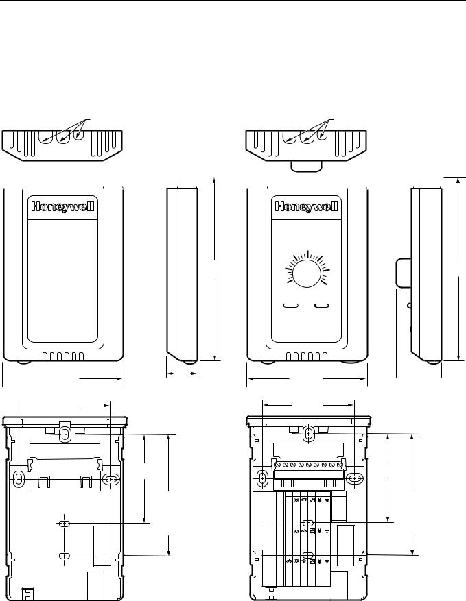
EXCEL 10 W7750A,B,C CONSTANT VOLUME AHU CONTROLLER
Wall Modules
The T7770 or T7560 Wall Modules for the Excel 5000 and Excel 10 Controllers are available in a variety of configurations. The models T7770A1006 and T7770C1002 are shown in Fig. 10. The T7770B,D are the same physical
size (see Product Names section for differences). The models T7560A1016 and T7560B1018 are shown in Fig. 11. The T7560A,B are the same physical size.
Duct Sensor
The dimensions of the C7770A duct-mounted sensor are shown in Fig. 12.
|
|
KNOCKOUTS FOR EUROPEAN |
|
|
|
|
KNOCKOUTS FOR EUROPEAN |
|||||||||
|
|
APPLIC ATIONS |
|
|
|
|
APPLIC ATIONS |
|||||||||
|
|
|
|
|
|
|
|
|
|
|
|
|
|
|
|
|
|
|
|
|
|
|
|
|
|
|
|
|
|
|
|
|
|
 3-5/32 (80)
 2-3/8 (60)
T7770A1006
|
65 |
70 |
75 |
|
|
||
5-1/16 |
60 |
|
80 |
(128) |
|
||
|
55 |
|
85 |
29/32 |
3-5/32 (80) |
(23) |
|
|
2-3/8 (60) |
2-3/8
(60)
STANDARD UTILITY
CONDUIT BOX (2 X 4) M OUNTING HOLES
|
|
1,2,3,4=on; 5=0ff |
9 |
8 |
7 |
6 |
5 |
4 |
3 |
2 |
1 |
S4 Settings: |
W7752 |
|
|
LED |
BYPASS/FAN |
SETPT |
SENSOR |
GND |
E-BUS |
E-BUS |
|
DIP Switch |
W7753 XL600-XL20 |
1,3,5=on; 2,4=off 2,4=on; 1,3,5=off |
LED RETURN |
BYPASS |
LED LED |
FAN BYPASS/FAN |
SETPT SETPT |
SENSOR SENSOR |
GND AL COM |
|
T7770C |
5-1/16
(128)
 1-1/4
1-1/4  (32)
(32)
2-3/8
(60)
STANDARD
UTILITY
CONDUIT
BOX (2 X 4)
MOUNTING
HOLES
M15119
Fig. 10. T7770A,B,C,D construction in in. (mm).
74-2958— 1 |
20 |
EXCEL 10 W7750A,B,C CONSTANT VOLUME AHU CONTROLLER
3-7/16
(86)
4
(100)
1 2 3 4 5 6 7 8
2-11/16 (68)
3-7/8 (97)
4-1/8
(104)
|
|
|
|
|
|
|
|
|
|
|
|
|
|
|
|
|
|
|
|
|
|
|
|
|
|
|
|
|
|
|
|
|
|
|
|
|
|
|
|
|
|
|
|
|
|
|
|
|
|
|
|
|
|
|
|
|
|
|
3-15/16 (99) |
|
|
|
|
|
|
|
|
|
|
1-3/16 (30) |
|||||
|
|
|
|
|
|
|
||||||||||||
|
|
|
|
|
|
|
|
|
|
|
|
|
|
|
|
|
|
|
M17479
Fig. 11. T7560A,B construction in in. (mm).
1-1/2 (38) |
8-1/2 (216) |
|
|
3/4 (19) |
1/2 (13) |
3/8 IN. (10) |
|
1/2 IN. (13) |
|||
|
|||
|
DIAMETER |
DIAMETER |
|
|
7/8 |
|
|
|
(22) |
|
|
|
|
3-1/2 (89) |
|
1/4 (6) |
1/2 (13) |
6-5/32 (156) |
|
DIAMETER (2 HOLES) |
M7724 |
||
|
Fig. 12. C7770A construction in in. (mm).
21 |
74-2958— 1 |

EXCEL 10 W7750A,B,C CONSTANT VOLUME AHU CONTROLLER
Configurations
General
Tables 3 and 4 provide an overview of the Excel 10 W7750 configuration options. All W7750s are assumed to have a supply fan digital output. Additionally, Tables 3 and 4 list the general mechanical equipment options available with the W7750 Controller. See Application Step 6. Configure Controllers, for further information on configurations.
 CAUTION
For floating control, the Excel 10 W7750 Controller is designed to work only with Series 60 valve and damper actuators. Full stroke actuator drive-time must be between 20 and 240 seconds (0.25 to 4.0 minutes).
Table 3. Common Configuration Options Summary For W7750A,B,C Controllers.
|
|
|
Option |
|
Possible Configurations Common To All W7750 Models |
|
|
|
Supply Fan |
1. |
Mandatory Digital Output. |
|
|
|
Type of Air Handler |
1. |
Conventional. |
|
|
|
|
2. |
Heat Pump. |
|
|
|
Occupancy Sensor |
1. |
None. |
|
|
|
|
2. |
Connected: Contacts closed equals Occupied. |
|
|
|
|
3. |
Network (Occ/Unocc signal received via the LONWORKS Bus network). |
|
|
|
Window Sensor |
1. |
None. |
|
|
|
|
2. |
Physically Connected: Contacts closed equals window closed. |
|
|
|
|
3. |
Network (Window Open/Closed signal received via the LONWORKS Bus). |
|
|
|
Wall Module Option |
1. |
Local (direct wired to the controller). |
|
|
|
(The T77560A,B has no LONWORKS Bus access) |
2. |
Network (sensor value received via the LONWORKS Bus). |
|
|
|
Wall Module Type |
1. |
Sensor only. |
|
|
|
(All wall modules have a LONWORKS Bus access |
2. |
Sensor and Setpoint adjust. |
|
|
|
jack except T7560A,B) |
3. |
Sensor, Setpoint adjust and Bypass. |
|
|
|
|
4. |
Sensor and Bypass. |
|
|
|
Smoke Emergency Initiation |
1. |
None. |
|
|
|
|
2. |
Physically Connected: Contacts closed equals smoke detected. |
|
|
|
|
3. |
Network (Emergency/Normal signal received via the LONWORKS Bus). |
|
|
|
74-2958— 1 |
22 |
|
|
|
|
|
EXCEL 10 W7750A,B,C CONSTANT VOLUME AHU CONTROLLER |
|
|
Table 4. Configuration Options Summary For W7750A,B,C Controllers. |
|||
|
|
|
|
|
|
|
|
Possible Configurations for the |
|
|
|
Option |
|
W7750A Model |
|
Possible Configurations for the W7750B,C Models |
|
|
|
|
|
|
|
Type of |
1. |
One stage. |
1. |
One stage. |
|
Heating |
|
|
|
|
|
2. |
Two stages. |
2. |
Two stages. |
||
|
|
|
|
|
|
|
3. |
Three stages. |
3. |
Three stages. |
|
|
|
|
|
|
|
|
4. |
Four stages. |
4. |
Four stages. |
|
|
|
|
|
|
|
|
5. |
None. |
5. |
Series 60 Modulating electric valve, or pneumatic via transducer. |
|
|
|
|
|
|
|
|
|
|
|
6. |
Pulse Width Modulating electric valve, or pneumatic via transducer. |
|
|
|
|
|
|
|
|
|
|
7. |
None. |
|
|
|
|
|
|
Type of |
1. |
One stage. |
1. |
One stage. |
|
Cooling |
|
|
|
|
|
2. |
Two stages. |
2. |
Two stages. |
||
|
|
|
|
|
|
|
3. |
Three stages. |
3. |
Three stages. |
|
|
|
|
|
|
|
|
4. |
Four stages. |
4. |
Four stages. |
|
|
|
|
|
|
|
|
5. |
None. |
5. |
Series 60 Modulating electric valve, or pneumatic via transducer. |
|
|
|
|
|
|
|
|
|
|
|
6. |
Pulse Width Modulating electric valve, or pneumatic via transducer. |
|
|
|
|
|
|
|
|
|
|
7. |
None. |
|
|
|
|
|
|
Type of |
1. |
Digital Output Enable/Disable |
1. |
Digital Output Enable/Disable signal for controlling an external |
|
Economizer |
|
signal for controlling an external |
|
economizer package. |
|
|
|
economizer package. |
|
|
|
|
|
|
|
|
|
|
2. |
Series 60 Modulating electric |
2. |
Series 60 Modulating electric damper motor, or pneumatic via |
|
|
|
damper motor, or pneumatic via |
|
transducer. |
|
|
|
transducer. |
|
|
|
|
|
|
|
|
|
|
3. |
None. |
3. |
Pulse Width Modulating electric damper motor, or pneumatic via |
|
|
|
|
|
|
transducer. |
|
|
|
|
|
|
|
|
|
|
4. |
None. |
|
|
|
|
|
|
IAQ Option |
1. |
None. |
1. |
None. |
|
|
|
|
|
|
|
|
2. |
Local IAQ Digital Input— directly |
2. |
Local IAQ Digital Input— directly wired to the controller. (Contacts |
|
|
|
wired to the controller. (Contacts |
|
closed means poor IAQ is detected.) |
|
|
|
closed means poor IAQ is |
|
|
|
|
|
detected.) |
|
|
|
|
|
|
|
|
|
|
3. |
Network (IAQ Override signal |
3. |
Network (IAQ Override signal received via the LONWORKS Bus). |
|
|
|
received via the LONWORKS Bus). |
|
|
|
|
|
|
|
|
|
|
|
|
|
4. Local CO2 Analog Input— directly wired to the controller. (The sensor |
|
|
|
|
|
|
must be a 0 to 10V device representing 0 to 2000 PPM CO2.) |
Coil Freeze |
1. |
None. |
1. |
None. |
|
Stat Option |
|
|
|
|
|
2. |
Local Coil Freeze Stat Digital |
2. |
Local Coil Freeze Stat Digital Input— directly wired to the controller. |
||
|
Input— directly wired to the controller. |
(Contacts closed means that coil freeze condition is sensed.) |
|||
|
(Contacts closed means that coil |
|
|
||
|
freeze condition is sensed.) |
|
|
||
|
|
|
|
|
|
Filter Monitor |
1. |
None. |
1. |
None. |
|
Option |
|
|
|
|
|
2. |
Local Dirty Filter Digital |
2. |
Local Dirty Filter Digital Input— directly wired to the controller. |
||
|
|
Input— directly wired to the |
|
(Contacts closed means that the filter is dirty.) |
|
|
|
controller. (Contacts closed means |
|
|
|
|
|
that the filter is dirty.) |
|
|
|
|
|
|
|
|
|
|
|
|
|
3. |
Local Analog Input for Differential Pressure across the Filter (directly |
|
|
|
|
|
wired to the controller). The sensor must be a 2 to 10V device |
|
|
|
|
|
representing 0 to 5 inw (1.25 kPa). |
|
|
|
|
|
|
23 |
74-2958— 1 |

EXCEL 10 W7750A,B,C CONSTANT VOLUME AHU CONTROLLER
Allowable Heating and Cooling Equipment Configurations
Each W7750 device can control a variety of different types of mechanical cooling and heating equipment within roof top air handlers. See Fig. 13 through 17 for a conceptual overview of some typical configurations. For specific wiring details, see the Prepare Wiring Diagrams section.
STAGED HEATING/COOLING CONTROL
Staged equipment control is available for up to four stages of heating or four stages of cooling. On the W7750, the stages are activated through digital outputs (Triacs on the W7750B,C and dry-contact relays on the W7750A) one for each stage wired to 24 Vac contactors (see Fig. 27 and 30 in Step 4. Prepare Wiring Diagrams section for wiring details). Note that the number of physical Digital Outputs (DOs) on the controller limits the total number of stages that can be controlled. For example, the W7750A Model has six digital outputs, and because one is used for the supply fan, there are five DOs available for any combination of heating and cooling stages (with a maximum of four stages of heating and four stages for cooling). The W7750B Model offers two additional DOs, for a total of eight. The W7750C offers five DOs and three Analog Outputs (AOs). Fig. 13 shows a typical application of two stages of heat and two stages of cooling.
|
|
COOL |
HEAT |
|
|
COIL |
COIL |
MIXED |
FAN |
|
DISCHARGE |
|
AIR |
||
AIR |
|
||
|
|
|
|
|
|
- |
+ |
FAN |
COMPRESSORS |
|
|
|
|
|
|
STARTER |
|
|
|
|
Y1 |
Y2 |
|
|
|
GAS COMBUSTION |
|
|
|
|
CONTROLS |
|
|
|
W1 W2 |
EXCEL 10 |
|
T7560A,B OR T7770 |
|
CVAHU |
|
|
|
W7750A,B,C |
|
|
|
M17491
Fig. 13. Fan with two stages of heating and two stages of cooling.
MODULATING HEATING/COOLING CONTROL
The W7750 Controller provides modulating equipment control for heating and cooling equipment (and economizer dampers, see Fig. 16) using either Series 60 Floating Control or Pulse Width Modulated (PWM) control, (PWM control is available on the W7750B,C only). The Series 60 Modulating Control is provided through two Relay digital outputs on the W7750A or two Triac digital outputs on the W7750B,C (one to pulse the valve actuator open and one to pulse it closed). PWM control
positions the actuator based on the length, in seconds, of the pulse from the digital output. For PWM, the controller outputs a pulse whose length consists of two parts, a minimum and a maximum. The minimum pulse time represents the analog value of 0 percent and the maximum pulse length that represents an analog value of 100 percent. If the analog value is greater than 0 percent, an additional time is added to the minimum pulse time. The length of time added is directly proportional to the magnitude of the analog value. The PWM actuator will begin to use the analog value at the end of the pulse and will continue to use this value until a new pulse is received. Refer to Appendix B under PWM Control for an example. Series 60 actuators are generally less expensive than those for PWM, but the trade-off is that PWM requires only a single controller digital output while floating control uses two DOs. Refer to Appendix B under Series 60 Modulating Control for an example. Fig. 14 illustrates a system with modulating heating and cooling (see Fig. 29 and 31 in Step 4. Prepare Wiring Diagrams section.
|
COOL |
HEAT |
|
|
COIL |
COIL |
|
MIXED |
|
DISCHARGE |
|
FAN |
AIR |
||
AIR |
|||
|
|
||
|
- |
+ |
|
FAN |
CHILLED |
HOT |
|
WATER |
WATER |
||
STARTER |
VALVE |
VALVE |
EXCEL 10 |
T7560A,B OR T7770 |
CVAHU
W7750A,B,C
M17492
Fig. 14. Fan, modulating heating and modulating cooling.
NOTE: Pneumatically actuated valves can be controlled using a pneumatic transducer device. See Fig. 17. Also, transducer devices are available from third party vendors to convert PWM outputs to a voltage or current signal if desired.
HEAT PUMP CONTROL
The W7750 Controller handles heat pump applications similarly to staged heating/cooling control. Heat pump applications are supported by providing outputs for up to four compressor stages, a change-over relay for the refrigerant reversing valve, and up to four stages of auxiliary heat. Note that the W7750A Model has six digital outputs, and therefore, with one DO used for the supply fan and one for the changeover relay, there are four outputs available for any combination of compressors and auxiliary heat stages. The W7750B Model offers two additional DOs for a total of eight, while the W7750C Model offers five DOs and 3 AOs. Fig. 15 illustrates a typical heat pump system with auxiliary heat.
74-2958— 1 |
24 |
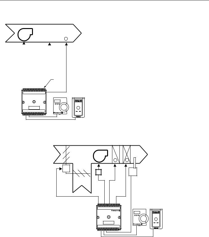
EXCEL 10 W7750A,B,C CONSTANT VOLUME AHU CONTROLLER
|
|
|
|
|
|
|
|
|
SHARED |
AUXILIARY |
||||||
|
|
|
|
|
|
|
|
|
HEAT AND |
HEAT |
||||||
|
|
|
|
|
|
|
|
|
COOL COIL |
STAGE(S) |
||||||
MIXED |
|
|
|
|
|
|
|
|
|
|
|
|
|
|
|
DISCHARGE |
|
|
|
|
|
|
|
|
|
|
|
|
|
|
|
||
FAN |
|
|
|
|
|
|
|
AIR |
||||||||
AIR |
|
|
|
|
|
|
|
|||||||||
|
|
|
|
|
|
|
|
|
|
|
|
|
|
|
|
|
|
|
|
|
|
|
|
|
|
|
|
|
|
|
+ |
|
|
|
|
|
|
FAN |
|
|
|
|
|
|
|
|
||||
|
|
|
|
|
|
|
|
|
|
|
|
|||||
|
|
|
|
|
|
|
|
|
|
|
|
|||||
|
|
|
|
STARTER |
|
|
|
|
|
|
|
|
||||
|
|
|
|
|
|
|
|
|
|
|
|
|
|
|
||
|
|
|
|
|
|
COMPRESSOR AND |
|
|
|
|
||||||
|
|
|
|
|
|
CHANGEOVER VALVE |
|
|
|
|
||||||
|
|
|
|
|
|
|
|
|
|
|
|
|
|
|
|
|
|
|
|
COMP 1 |
|
|
CHANGEOVER |
||||||||||
|
|
|
|
|
|
|
|
|
|
|
|
RELAY |
||||
|
|
|
|
COMP 2 |
|
|
|
|
||||||||
|
|
|
|
|
|
|
|
|
|
|
|
|
||||
|
|
|
|
|
|
|
|
|
|
|
|
|
|
|
|
|
EXCEL 10
CVAHU 


 T7560A,B OR T7770 W7750A,B,C
M17493
ECONOMIZER CONTROL
Economizer control is available concurrently with any configuration in the W7750 when DOs are not all used by the heating and cooling equipment. Two types of economizer controls are supported by the W7750 Controller, modulating control and enable/disable control. Modulating control can be either Series 60 Floating Control or PWM control (PWM control is available on the W7750B,C only). A discharge air temperature sensor is required for modulating economizer damper control. Enable/disable control is provided to emulate the Honeywell T7300 thermostat economizer operation, where a DO tracks the occupancy status of the controller. An external packaged economizer control then modulates the dampers. For modulating control, the economizer is enabled or disabled based on one of ten available strategies (see Appendix B— Sequences of Operation— Economizer Enable/ Disable Control section, for further details). Fig. 16 illustrates a system with modulating economizer dampers (see Fig. 29, 31, 32 and 35 in Step 4. Prepare Wiring Diagrams section, for wiring details).
Fig. 15. Heat pump with two compressors and auxiliary heat stage(s).
|
COOL |
HEAT |
|
|
COIL |
COIL |
|
OUTDOOR |
FAN |
DISCHARGE |
|
AIR |
|||
AIR |
|||
- |
+ |
||
|
M |
|
FAN |
DISCHARGE |
|
|
TEMPERATURE |
|
|
|
STARTER |
|
|
|
SENSOR REQUIRED |
|
PWM OR |
|
|
|
|
|
FOR ECONOMIZER |
|
SERIES 60 |
|
|
|
RETURN |
|
CONTROL |
|
FLOATING |
|
||
AIR |
|
|
|
MOTOR |
|
|
|
|
|
|
|
|
EXCEL 10 |
|
T7560A,B OR T7770 |
|
CVAHU |
|
|
|
W7750A,B,C |
|
|
M17494
Fig. 16. Economizer control.
PNEUMATIC ACTUATOR CONTROL
The W7750B,C Controller can control pneumatic actuators for any or all of the three modulating outputs provided by the control algorithm (heat, cool and economizer). Control of pneumatic water/steam valves and damper actuators is provided through a transducer device using either Series 60 Floating Control or PWM DOs. A floating-to-pneumatic, or a PWM-to-pneumatic transducer is required for each output signal. The W7750A Controller can drive Series 60 Floating
Control to modulate cooling valves, heating valves and economizers. There are no PWM outputs configurable on the W7750A model.
For projects with existing pneumatically actuated reheat valves, the Excel 10 W7750 Controller output must be converted to a pneumatic signal using a transducer device developed for use with Excel 10 Controllers. The transducer is
25 |
74-2958— 1 |
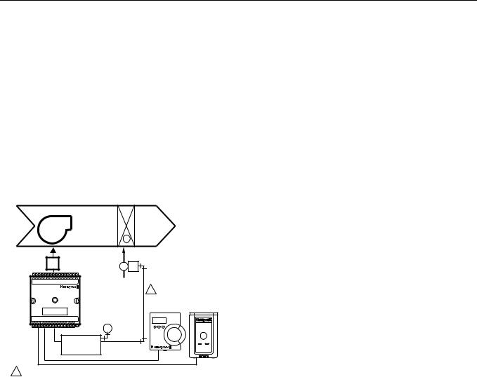
EXCEL 10 W7750A,B,C CONSTANT VOLUME AHU CONTROLLER
available through Honeywell, or directly from the manufacturer, Mamac Systems (see Table 11 for ordering information).
Fig. 17 depicts a typical W7750 System with modulating heating valve using a pneumatic valve actuator. Also see Fig. 36 for wiring an MMC325 Pneumatic Transducer to a W7750A,B,C Controller and Fig. 37 for wiring a RP7517B Pneumatic Transducer to a W7750C Controller.
NOTE: When choosing the pneumatic pressure range, make sure that the close-off pressure is 2 to 3 psi greater than that of the spring range. When using a spring range of 5 to 10 psi with 10 psi as the closed position, do not use the 0 to 10 psi model of the MMC325 Transducer; use the 0 to 20 psi transducer as the recommended selection.
|
|
HEAT |
|
|
|
COIL |
|
MIXED |
FAN |
DISCHARGE |
|
AIR |
AIR |
||
|
|||
|
|
+ |
|
FAN |
|
PNEUMATIC |
|
|
ACTUATOR |
||
STARTER |
|
VALVE |
1
T7560A,B OR T7770
|
M |
MMC325 |
PNEUMATIC |
|
TRANSDUCER |
1PNEUMATIC MAIN OR BRANCH LINE MUST BE 1/4 IN. (6 MM) OR LARGER TUBING. A MINIMUM OF 6 FT (1.8M) OF TUBING
IS NEEDED IN A BRANCH LINE. |
M17495 |
Fig. 17. Modulating heat with pneumatic valve actuator.
MIXED-OUTPUT-TYPE CONTROL
The W7750B,C Controller provides control for mixed-output- types of applications such as PWM heating and staged cooling control occurring simultaneously with Series 60 Floating Economizer Damper Control.
Occupancy Sensor
Excel 10 W7750 Controllers provide a digital input for connection to an occupancy sensor. This is a device, such as a passive infrared motion detector, that contains a dry contact (see following NOTE) closure to indicate whether or not people are present in the space. The Excel 10 W7750 Controller expects a contact closure to indicate the space is Occupied. See Fig. 27 through 35 in Application Step 4, Prepare Wiring Diagrams, for details on wiring connections.
The control algorithm in the Excel 10 Controller uses the occupancy sensor, if configured, to determine the Effective Occupancy (see Table 5) mode of operation. If the Time Of Day (TOD) schedule indicates an Occupied state, and the occupancy sensor contact is closed, the Effective Occupancy mode is Occupied. However, if the TOD schedule indicates an Occupied state and the occupancy sensor contact is open,
then the Effective Occupancy mode is STANDBY. The temperature control algorithm is then controlled to the STANDBY Cooling and Heating Setpoints.
If the occupancy sensor is not configured, a local controller can be put in the STANDBY mode only by either a one-to-one association of the occupancy sensor from another Excel 10 Controller to the local controller, or by receiving the STANDBY mode signal via the LONWORKS Bus.
NOTE: The Excel 10 Controller has limited power available (only 9 mA at 4.8 volts) for checking the digital inputs for contact closures. It is very important that the device used contains high quality, noncorroding contacts with resistivity that does not degrade; that is, increase over time. Use noble metal (such as gold or silver), or pimpled or sealed contacts to assure consistent, long-term operation.
The recommended devices for use with the Excel 10 W7750 Controllers are the EL7628A1007 Ceiling Mounted Infrared or the EL7680A1008 Wall Mounted Wide View Infrared Occupancy Sensors. If ultrasonic sensors are required, the EL7611A1003 and the EL7612A1001 Occupancy Sensors are recommended. An EL76XX Power Supply/Control Unit is required for use with these occupancy sensors. The EL7630A1003 can power up to four sensors, and is multitapped for several line voltages. The EL7621A1002 can power three sensors and it connects to 120 Vac line voltage. The EL7621A1010 can also power three sensors but it connects to 277 Vac line voltage.
Window Open/Closed Digital Input
A digital input is also provided for detecting whether a window in the space was opened. The Excel 10 W7750 Controller can be connected to a dry contact (see the following NOTE and Fig. 27 through 35 in Application Step 4. Prepare Wiring Diagrams, for details) or a set of contacts wired in series (for monitoring multiple windows) to verify that the window(s) are closed. The algorithm expects a contact closure to indicate the window is closed. If an open window is detected, the algorithm changes the mode of operation to FREEZE_PROTECT, which shuts down the control functions, and watches for low space temperature conditions. The frost protection setpoint is 46.4° F (8° C), and the frost alarm occurs at 42.8° F (6° C).
NOTE: (This is the same NOTE as in the Occupancy Sensor section.) The Excel 10 has limited power available (only 9 mA at 4.8 volts) for checking the digital inputs for contact closures. It is very important that the device used contains high quality, noncorroding contacts with resistivity that does not degrade; that is, increase over time. Use noble metal (such as gold or silver), or pimpled or sealed contacts to assure consistent, long-term operation.
Wall Module Options
As previously discussed, there are four basic varieties of the T7770 Wall Modules and two of the T7560 Digital Wall Module (see the Product Names and the Construction sections). Also, a T7770 and T7560 Wall Modules can be shared among two or more W7750s. The control algorithm must be given this wall module information when configuring the W7750 (see Excel E-Vision User’s Guide, form 74-2588).
74-2958— 1 |
26 |

EXCEL 10 W7750A,B,C CONSTANT VOLUME AHU CONTROLLER
Dirty Filter Monitor
The air filter in the air handler can be monitored by the W7750 and an alarm is issued when the filter media needs replacement. The two methods of monitoring the filter are:
1.Connecting a differential pressure switch to a digital input on the W7750A or W7750B,C.
2.Wiring a 2 to 10V differential pressure sensor to a voltage input on the W7750B,C. If the analog input sensor is used, its measured value 0 to 5 inw (0 to 1.25 kPa) is compared to a user-selectable setpoint (FltrPressStPt— valid range: 0 to 5 inw (0 to 1.25 kPa)), and the Dirty Filter alarm is issued when the pressure drop across the filter exceeds the setpoint.
Indoor Air Quality (IAQ) Override
The Excel 10 W7750 Controller provides IAQ ventilation control using one of two different methods of detecting poor air quality. The first is with an IAQ switch device connected to a digital input on the W7750 Controller, where a contact closure indicates poor air quality, and initiates the IAQ Override mode. The device can detect poor air quality using any desired measure such as CO2, VOC, CO, etc. The second method, which is only available on the W7750B,C, is through an analog input that connects to a CO2 sensor (2 to 10V). The measured value of CO2 from this sensor (0 to 2000 PPM) is compared to the setpoint (IAQSetpt). When the CO2 level is higher than the setpoint (800 PPM adjustable), the
IAQ Override is initiated. The IAQSetpt hysteresis is 50 PPM, IAQ Override is deactivated at a CO2 level less than 50 PPM below setpoint.
The effect of initiating the IAQ Override mode is that the economizer dampers are allowed to open above the standard minimum position setting to allow more fresh air to enter the building. See Appendix B— Sequences of Operation, for further control details.
Smoke Control
The Excel 10 W7750 Controller supports smoke-related control strategies that are initiated either via a network command (DestEmergCmd) or from a local (physically connected) smoke detector digital input. The details of the W7750 smoke-related control operation are described in Appendix B— Sequences of Operation.
Freeze Stat
A freeze stat can be monitored by the W7750 and issue a freeze stat alarm indicating the CVAHU is in danger of freezing its coil. The details of the W7750 freeze stat related control operation are described in Appendix B— Sequences of Operation.
Modes of Operation
The possible modes of operation for the W7750 Controller are listed in Table 5.
Table 5. Modes Of Operation For The Excel 10 W7750 Controller .
|
|
|
Mode |
Description |
Events causing a controller to switch to this mode |
|
|
|
Effective Occupancy (User Address: StatusOcc) |
|
|
|
|
|
OCCUPIED |
Controller is in Occupied mode |
Any of the following: Network input (DestSchedOcc) containing a |
|
|
time-of-day schedule flag from either the Excel 10 Zone Manager or an |
|
|
LONWORKS Bus Controller; Time Clock DI, Occupancy Sensor DI; or |
|
|
from Network input (DestManMode) for manual override to OCC mode. |
|
|
DestManMode has the highest priority, followed by the Time Clock DI, |
|
|
and then DestSchedOcc. |
|
|
|
STANDBY |
Controller is in Standby mode |
Either: (A) Network input (DestSchedOcc) containing a time-of-day |
|
|
schedule flag from the Excel 10 Zone Manager or other LONWORKS |
|
|
Bus node is STANDBY, or (B) Network input (DestSchedOcc) is |
|
|
OCCUPIED and the Occupancy Sensor DI is UNOCCUPIED. |
|
|
|
UNOCCUPIED |
Controller is in Unoccupied mode |
Network input (DestSchedOcc) containing a time-of-day schedule flag |
|
|
from the Excel 10 Zone Manager or LONWORKS Bus, or the network |
|
|
input DestManOcc has a value of UNOCCUPIED. |
|
|
|
BYPASS |
Controller is in Occupied mode through |
This mode is derived from the schedule occupancy (DestSchedOcc) |
OCCUPIED |
a Bypass command |
having a state of UNOCCUPIED and a manual request for occupancy |
|
|
from one of three sources. Two of these are signals originated external |
|
|
to the unit, and received by DestManOcc and DestBypass. The third |
|
|
source for an occupancy request is from an override button located on |
|
|
a wall module. These three sources are arbitrated in a scheme |
|
|
determined by the configuration parameter (Network Wins or Last-in |
|
|
Wins from OvrdPriority). |
|
|
|
Override Modes (User Address: StatusOvrd) |
|
|
|
|
|
OCCUPIED |
Controller occupancy mode was |
Network input (DestManOcc) containing a time-of-day schedule |
|
overridden to Occupied mode |
override signal of OCCUPIED from the Excel 10 Zone Manager or |
|
|
other LONWORKS Bus device. |
|
|
|
STANDBY |
Controller occupancy mode was |
Network input (DestManOcc) containing a time-of-day schedule |
|
overridden to Standby mode |
override signal of STANDBY from the Excel 10 Zone Manager or other |
|
|
LONWORKS Bus device. |
|
|
|
27 |
74-2958— 1 |

EXCEL 10 W7750A,B,C CONSTANT VOLUME AHU CONTROLLER
Table 5. Modes Of Operation For The Excel 10 W7750 Controller (Continued).
|
|
|
Mode |
Description |
Events causing a controller to switch to this mode |
|
|
|
UNOCCUPIED |
Controller occupancy mode was |
Network input (DestManOcc) containing a time-of-day schedule |
|
overridden to Unoccupied mode |
override signal of UNOCCUPIED from the Excel 10 Zone Manager or |
|
|
other LONWORKS Bus device. |
|
|
|
BYPASS |
Controller occupancy mode was |
DI (Bypass) was pressed, and the Bypass duration timer has not yet |
|
overridden to Bypass the current |
expired, or the network input DestManOcc has a value of BYPASS. |
|
Unoccupied mode |
|
|
|
|
NOT |
No Bypass action |
No Override input received. |
ASSIGNED |
|
|
|
|
|
Operational Modes (User Address: StatusMode) |
|
|
|
|
|
START-UP |
On power-up, provides a staggered |
This mode occurs on controller power-up, and after downloading to the |
AND WAIT |
start sequence to evenly apply the load |
controller from the configuration tool. Temperature control loops are |
|
to the electrical system. |
disabled. |
|
|
|
COOLING |
The Excel 10 is controlling the Cooling |
Space temperature has risen above the current cooling setpoint, or the |
|
mode. |
network input (DestHvacMode) is COOL. |
|
|
|
HEATING |
The Excel 10 is controlling the Heating |
Space temperature has fallen below the current heating setpoint, or the |
|
mode. |
network input (DestHvacMode) is HEAT. |
|
|
|
EMERGENCY |
Compressors are disabled and only |
The network input (DestManHvacMode) is EMERG_HEAT. |
HEAT |
Auxiliary Heat stages are allowed to |
|
|
operate. |
|
|
|
|
OFF MODE |
The heat/cool control is turned off |
Network input (DestManMode) containing AHU operational mode |
|
immediately. The node is not running its |
information from C-Bus has value of MORNING WARM-UP. |
|
normal temperature control. |
|
|
|
|
DISABLED |
The heat/cool control and frost |
– |
MODE |
protection are turned off immediately. |
|
|
The node is not running its normal |
|
|
temperature control. |
|
|
|
|
SMOKE |
The node has entered a smoke |
Network input (DestEmergCmd) containing smoke control signal from |
EMERGENCY |
emergency. The fan and dampers are |
another LONWORKS Bus device has value of SMOKE_EMERG. |
|
then set to the conditions configured by |
|
|
SmkCtlMode. The control remains in |
|
|
SMOKE_ EMERGENCY until power is |
|
|
cycled or the node receives |
|
|
DestEmergCmd set to |
|
|
EMERG_NORMAL. |
|
|
|
|
FREEZE |
The temperature control is set to HEAT |
The Window digital input detects an open window. |
PROTECT |
with the setpoint set to the frost limit |
|
|
setpoint 46.4°F (8°C). |
|
|
|
|
MANUAL |
The physical outputs are being |
Typically this is done by the user through E-Vision or XBS by setting |
POSITION |
controlled manually. The temperature |
the point DestManMode to MANUAL mode. |
|
control loop is turned off. |
|
|
|
|
FAN ONLY |
Control algorithm is disabled, except |
The space temperature sensor has failed, or the network input |
|
that the fan is turned on. |
(DestHvacMode) is FAN ONLY. |
|
|
|
DISABLED |
Control algorithm is shut off. |
Network input (DestManMode) containing AHU operational mode |
|
|
information from an operator or the network that has a value of |
|
|
DISABLED. |
|
|
|
NOTE: During all modes all digital and analog physical inputs are periodically read, the diagnostic output network variables can be polled, the input network variables are received, and the output network variables are sent periodically.
74-2958— 1 |
28 |

EXCEL 10 W7750A,B,C CONSTANT VOLUME AHU CONTROLLER
APPLICATION STEPS
Overview
The seven application steps shown in Table 6 are planning considerations for engineering an Excel 10 W7750 System. These steps are guidelines intended to aid understanding of the product I/O options, bus arrangement choices, configuration options and the Excel 10 W7750 Controller role in the overall EXCEL 5000 OPEN SYSTEM architecture.
|
Table 6. Application Steps. |
|
|
Step No. |
Description |
|
|
1 |
Plan The System |
|
|
2 |
Determine Other Bus Devices Required |
|
|
3 |
Lay Out Communications and Power Wiring |
|
|
4 |
Prepare Wiring Diagrams |
|
|
5 |
Order Equipment |
|
|
6 |
Configure Controllers |
|
|
7 |
Troubleshooting |
|
|
Step 1. Plan the System
Plan the use of the W7750 Controllers according to the job requirements. Determine the location, functionality and sensor or actuator usage. Verify the sales estimate of the number of W7750 Controllers, T7770 and T7560 Wall Modules required for each model type. Also check the number and type of output actuators and other required accessories.
When planning the system layout, consider potential expansion possibilities to allow for future growth. Planning is very important to be prepared for adding HVAC systems and controllers in future projects.
T7560 Wall Modules can only be hard-wired, they have no LONWORKS Bus access. T7770 Wall Modules can be installed as either hard-wired I/O-only devices or additional wiring can be run to them (for the LONWORKS Bus network) to allow a CARE/E-Vision operator terminal to have access to the LONWORKS Bus. The application engineer needs to determine how many wall modules, T7770s and T7560s are required. All T7770 Wall Modules, except the T7770A1006 and the T7770A1014, can be connected via the LONWORKS Bus jack. Also the application engineer needs to know how many T7770s without LONWORKS Bus network connections are being installed on the job, and then clearly document which wall modules (if any) have network access. This information is required during installation to ensure that the proper number and type of wires are pulled to the wall modules, and the building operators are informed about where they can plug in to the LONWORKS Bus network with a portable operator terminal (see Fig. 18, 19 and 20). Refer to Step 4. Prepare Wiring Diagrams for details, about the about the wiring differences between the two types.
|
EXCEL 10 |
|
|
|
W7750 |
|
|
|
CVAHU |
|
|
|
CONTROLLER |
||
NOTEBOOK PC |
|
|
|
|
SHIELDED |
||
|
INTERFACE |
||
|
CABLE |
||
EIA-232 |
Q7752A |
|
|
SERIAL |
|
||
PORT |
SLTA |
|
|
CABLE |
|
||
PART |
LONWORKS BUS |
||
NO. 205979 |
|||
PORT |
|||
|
|
||
M15120A
Fig. 18. Connecting the portable operator terminal to the LONWORKS® Bus.
The FTT communication wiring, (LONWORKS Bus) between controllers is a free topology scheme that supports T-tap, star, loop, and mixed wiring architecture. Refer to the LONWORKS Bus Wiring Guidelines form, 74-2865 for complete description of network topology rules. See Application Step 3. Lay Out Communications and Power Wiring, for more information on bus wiring layout, and see Fig. 27 through 35 in Application Step 4. Prepare Wiring Diagrams, for wiring details.
The application engineer must review the Direct Digital Control (DDC) job requirements. This includes the Sequences of Operation for the W7750 units, and for the system as a whole. Usually there are variables that must be passed between the W7750 Controllers and other zone controller(s), or central plant controller(s) that are required for optimum system-wide operation. Typical examples are the TOD Occ/ Unocc signal, the outdoor air temperature, the demand limit control signal, and the smoke control mode signal.
It is important to understand these interrelationships early in the job engineering process to ensure implemention when configuring the controllers. (See Application Step 6. Configure Controllers, for information on the various Excel 10 parameters and on Excel 10 point mapping.)
Step 2. Determine Other Bus Devices Required
A maximum of 62 nodes can communicate on a single LONWORKS Bus segment. Each W7750 (CVAHU) Controller constitutes one node. If more nodes are required, a Q7751A,B Router is necessary. Using a router allows up to 125 nodes, divided between two LONWORKS Bus segments. The router accounts for two of these nodes (one node on each side of the router); a Q7750A Excel 10 Zone Manager takes one node and two nodes are available for operator terminal nodes, leaving 120 nodes available for Excel 10 Controllers. All 120 controllers are able to talk to each other through the router. A Q7750A Excel 10 Zone Manager is required to connect the LONWORKS Bus to the standard EXCEL 5000 OPEN System C-Bus. Each Excel 10 Zone Manager supports up to 120 Excel 10 Controllers. This limit is set in the Excel 10 Zone Manager database as an absolute maximum.
29 |
74-2958— 1 |

EXCEL 10 W7750A,B,C CONSTANT VOLUME AHU CONTROLLER
Each LONWORKS Bus segment is set up with two unused nodes to allow for a CARE/E-Vision operator terminal to be connected to the LONWORKS Bus. Multiple CARE/E-Vision
terminals can be connected to the LONWORKS Bus at the same time. Table 7 summarizes the LONWORKS Bus segment configuration rules.
Table 7. LONWORKS® Bus Configuration Rules And Device Node Numbers.
|
|
One LONWORKS Bus Segment Example |
Maximum Number of Nodes Equals 62 |
|
|
One Q7750A Excel 10 Zone Manager |
1 node |
|
|
Port for operator terminal access (CARE/E-Vision) |
1 node |
|
|
Maximum number of Excel 10s |
60 nodes |
|
|
Total |
62 nodes |
|
|
|
|
Two LONWORKS Bus Segments Example |
Maximum Number of Nodes Equals 125 |
|
|
One Q7750A Excel 10 Zone Manager |
1 node |
|
|
One Q7751A,B Router |
2 nodes (1 in each Bus Segment) |
|
|
Ports for operator terminal access (two CARE/E-Vision |
2 nodes (1 in each Bus Segment) |
terminals) |
|
|
|
Maximum number of Excel 10s in segment number one |
60 nodes |
|
|
Maximum number of Excel 10s in segment number two |
60 nodes |
|
|
Total |
125 nodes |
|
|
Refer to the LONWORKS Bus Wiring Guidelines form, 74-2865 for complete description of network topology rules and the maximum wire length limitations. If longer runs are required, a Q7740A 2-Way or Q7740B 4-Way Repeater can be added to extend the length of the LONWORKS Bus. A Q7751A,B Router can be added to partition the system into two segments and effectively double the length of the LONWORKS Bus. Only one router is allowed with each Excel 10 Zone Manager, and each network segment can have a maximum of one repeater.
In addition, all LONWORKS Bus segments require the installation of a 209541B Termination Module for a singly terminated LONWORKS Bus or two 209541B Termination Modules for a doubly terminated LONWORKS Bus. For more details on LONWORKS Bus termination, refer to the LONWORKS Bus Wiring Guidelines form, 74-2865, or see Application Step 3. Lay Out Communications and Power Wiring, and the LONWORKS Bus Termination Module subsection in Application Step 4.
Step 3. Lay Out Communications and Power
Wiring
LONWORKS® Bus Layout
The communications bus, LONWORKS Bus, is a 78-kilobits per second (kbps) serial link that uses transformer isolation and differential Manchester encoding. Approved cable types for LONWORKS Bus communications wiring is Level IV 22 AWG (0.34 mm2) plenum or non-plenum rated unshielded, twisted
pair, solid conductor wire. For nonplenum areas, use Level IV 22 AWG (0.325 mm2), such as U.S. part AK3781 (one pair) or U.S. part AK3782 (two pair). In plenum areas, use plenumrated Level IV, 22 AWG (0.325 mm2) such as U.S. part AK3791 (one pair) or U.S. part AK3792 (two pair). See Tables 9 and 11 for part numbers. Contact Echelon Corp. Technical Support for the recommended vendors of Echelon approved cables. The FTT communications bus, LONWORKS Bus, supports a polarity insensitive, free topology wiring scheme that supports T-tap, star, loop, and mixed bus wiring.
LONWORKS Bus networks can be configured in a variety of ways, so refer to the LONWORKS Bus Wiring Guidelines form, 74-2865 for complete description of network topology rules and Table 7. Fig. 19 and 20 depict two typical LONWORKS Bus network topologies; One has only one doubly terminated LONWORKS Bus segment that has 60 nodes or less, and one showing two singly terminated LONWORKS Bus segments that has 120 nodes or less (60 MAX per each segment). The bus configuration is set up using the Network Manager tool from within CARE (see the CARE Excel 10 Zone Manager User’s Guide, form 74-1392).
NOTE: For wiring details see the LONWORKS Bus Termination Module subsection in Step 4. For wall module wiring, U.S. part AK3782 (non-plenum) or U.S. part AK3792 (plenum) can be used. For a LONWORKS Bus that is a doubly terminated daisychain, these cables contain two twisted pairs (one for the run down to the wall module, and one for the run back up to the controller) for ease of installation.
74-2958— 1 |
30 |
Loading...