


 Loading...
Installation Manual
MARINE RADAR FR-2115-B/FR-2125-B
SAFETY INSTRUCTIONS................... |
i |
||
EQUIPMENT LISTS ........................... |
iii |
||
SYSTEM CONFIGURATION .............. |
vi |
||
1. |
MOUNTING |
|
|
|
1.1 |
Antenna Unit.................................... |
1-1 |
|
1.2 |
Processor Unit................................. |
1-6 |
|
1.3 |
Monitor............................................. |
1-9 |
|
1.4 |
Control Unit.................................... |
1-11 |
2. |
WIRING |
|
|
|
2.1 |
Antenna Unit.................................... |
2-1 |
|
2.2 |
Processor Unit................................. |
2-5 |
|
2.3 |
Monitor............................................. |
2-8 |
|
2.4 |
Control Unit.................................... |
2-10 |
|
2.5 |
External Equipment ....................... |
2-11 |
|
2.6 AC Power Specification of |
|
|
|
|
Processor Unit............................... |
2-13 |
3. INITIALIZATION AND ADJUSTMENT
3.1 |
Tuning Initialization.......................... |
3-1 |
3.2 |
Accessing Menus for Initialization and |
|
|
Adjustment ....................................... |
3-1 |
3.3 |
Adjusting Video Signal Level........... |
3-1 |
3.4 |
Heading Alignment .......................... |
3-2 |
3.5 |
Adjusting Sweep Timing.................. |
3-3 |
3.6 |
Suppressing Main Bang .................. |
3-3 |
3.7 |
Confirming Magnetron Heater |
|
|
Voltage ............................................ |
3-4 |
3.8 |
Initial Setting Menus ........................ |
3-5 |
4. OPTIONAL EQUIPMENT
4.1 |
Gyro Converter GC-8 ...................... |
4-1 |
4.2 |
ARP Board ARP-26......................... |
4-7 |
4.3 |
RP Board RP-26.............................. |
4-9 |
4.4 |
Performance Monitor PM-30 ......... |
4-13 |
4.5 |
Alarm Kit ........................................ |
4-14 |
4.6 |
AC-DC Conversion Kit................... |
4-15 |
PACKING LISTS ............................. |
A-1 |
|
OUTLINE DRAWINGS.................... |
D-1 |
|
INTERCONNECTION DIAGRAM ... |
S-1 |
|
SCHEMATIC DIAGRAMS ............... |
S-2 |
|
C
9 - 5 2 , A s h i h a r a - c h o , N i s h i n o m i y a , J a p a n
T e l e p h o n e : |
0 7 9 8 - 6 5 - 2 1 1 1 |
T e l e f a x : |
0 7 9 8 - 6 5 - 4 2 0 0 |
A l l r i g h t s r e s e r v e d .  Printed in Japan
P U B . N o . I M E - 3 4 8 3 0 - H
( T E N I ) |
F R - 2 1 1 5 / 2 1 2 5 - B |
|
 Y o u r L o c a l A g e n t / D e a l e r
F I R S T E D I T I O N |
: |
J U L . 1 9 9 9 |
H |
: |
N O V . 0 5 , 2 0 0 1 |


 SAFETY INSTRUCTIONS
 WARNING
Radio Frequency Radiation Hazard
The radar antenna emits electromagnetic radio frequency (RF) energy which can be harmful, particularly to your eyes. Never look directly into the antenna aperture from a close distance while the radar is in operation or expose yourself to the transmitting antenna at a close distance.
Distances at which RF radiation levels of 100 and 10 W/m2 exist are given in the table below.
Note: If the antenna unit is installed at a close distance in front of the wheel house, your administration may require halt of transmission within a certain sector of antenna revolution. This is possible - ask your FURUNO representative or dealer to provide this feature.
Model |
Radiator |
Distance to |
Distance to |
|
100 W/m2 |
10 W/m2 |
|||
type |
||||
|
point |
point |
||
|
|
|||
|
|
|
|
|
|
XN12AF |
0.1 m |
3.5 m |
|
|
|
|
|
|
FR-2115-B |
XN20AF |
0.1 m |
3.5 m |
|
|
|
|
|
|
|
XN24AF |
0.1 m |
3.5 m |
|
|
|
|
|
|
|
XN12AF |
1.1 m |
1.4 m |
|
|
|
|
|
|
FR-2125-B |
XN20AF |
1.1 m |
10.0 m |
|
|
|
|
|
|
|
XN24AF |
1.1 m |
10.0 m |
|
|
|
|
|
i
 WARNING
|
Do not open the equipment |
|
|
unless totally familiar with |
|
|
electrical circuits and |
|
|
service manual. |
|
ELECTRICAL |
Only qualified personnel |
|
should work inside the |
||
SHOCK |
||
HAZARD |
equipment. |
|
|
|
|
|
Wear a safety belt and hard |
|
|
hat when working on the |
|
|
antenna unit. |
Serious injury or death can result if someone falls from the radar antenna mast.
Construct a suitable service platform from which to install the antenna unit.
Serious injury or death can result if someone falls from the radar antenna mast.
Turn off the power at the mains switchboard before beginning the installation.
Fire, electrical shock or serious injury can result if the power is left on or is applied while the equipment is being installed.
Do not install the display unit where it may get wet from rain or water splash.
Water in the display unit can result in fire, electrical shock or equipment damage.
 WARNING
Be sure that the power supply is compatible with the voltage rating of the equipment.
Connection of an incorrect power supply can cause fire or equipment damage. The voltage rating of the equipment appears on the label above the power connector.
Use only the specified power cable.
Fire or equipment damage can result if a different cable is used.
 CAUTION
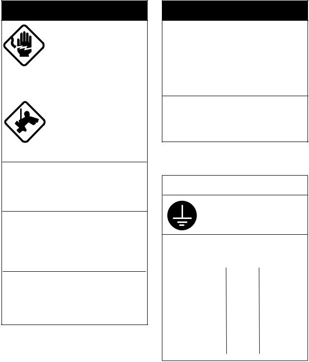
Ground the equipment to prevent electrical shock and mutual interference.
Observe the following compass safe distances to prevent interference to a magnetic compass:
|
Standard |
Steering |
|
|
compass |
compass |
|
|
|
|
|
Processor |
1.70 m |
0.90 m |
|
unit |
|||
|
|
||
|
|
|
|
Antenna |
1.70 m |
0.90 m |
|
unit |
|||
(FR-2115-B) |
|
|
|
|
|
|
|
Antenna |
2.10 m |
1.20 m |
|
unit |
|||
|
|
||
(FR-2125-B) |
|
|
|
|
|
|
ii

EQUIPMENT LISTS
Standard supply (System with monitor)
Name |
Type |
Code No. |
Qty |
Remarks |
|
|
|
XN12AF-RSB-0074-062 |
− |
|
FR-2115-B, 24 rpm, 1200 mm |
CP03- |
|
|
|
|
|
|
24201 |
|
|
XN12AF-RSB-0075-062 |
− |
|
FR-2115-B, 42 rpm, 1200 mm |
||
|
|
|
|
|
|
|
|
XN20AF-RSB-0074-062 |
− |
|
FR-2115-B, 24 rpm, 2000 mm |
CP03- |
|
|
|
|
|
|
19101 |
|
|
XN20AF-RSB-0075-062 |
− |
|
FR-2115-B, 42 rpm, 2000 mm |
||
|
XN24AF-RSB-0074-062 |
− |
|
FR-2115-B, 24 rpm, 2400 mm |
|
|
|
|
|
|
|
|
|
Antenna |
XN24AF-RSB-0075-062 |
− |
1 |
FR-2115-B, 42 rpm, 2400 mm |
|
|
Unit |
XN12AF-RSB-0074-063 |
− |
FR-2125-B, 24 rpm, 1200 mm |
CP03- |
||
|
||||||
|
|
|
|
|
24201 |
|
|
XN12AF-RSB-0075-063 |
− |
|
FR-2125-B, 42 rpm, 1200 mm |
||
|
|
|
|
|
|
|
|
XN20AF-RSB-0074-063 |
− |
|
FR-2125-B, 24 rpm, 2000 mm |
CP03- |
|
|
|
|
|
|
19101 |
|
|
XN20AF-RSB-0075-063 |
− |
|
FR-2125-B, 42 rpm, 2000 mm |
||
|
XN24AF-RSB-0074-063 |
− |
|
FR-2125-B, 24 rpm, 2400 mm |
|
|
|
|
|
|
|
|
|
|
XN24AF-RSB-0075-063 |
− |
|
FR-2125-B, 42 rpm, 2400 mm |
|
|
|
|
|
|
|
|
|
Monitor |
RDP-124-M-ES |
− |
1 |
|
|
|
|
|
|
|
|
|
|
Control Unit |
RCU-011 |
− |
1 |
|
|
|
|
|
|
|
|
|
|
Processor |
RPU-011 |
− |
1 |
|
|
|
Unit |
|
|
||||
|
|
|
|
|
||
Spare Parts |
SP03-12500 (DC mains) |
000-089-390 |
1 set |
SP03-12501, SP03-12505 |
|
|
|
|
|
|
|
||
|
SP03-12510 (AC mains) |
000-089-391 |
SP03-12501, SP03-12506 |
|
||
|
|
|
||||
|
|
|
|
|
|
|
Accessories |
FP03-07410 |
000-089-584 |
|
FP03-07401: Accessories |
|
|
|
|
|
|
FP03-06201: Handle |
|
|
|
|
|
1 set |
FP03-06502: Accessories |
|
|
|
|
|
|
FP03-06503: Hood |
|
|
|
|
|
|
Dust cover 03-144-1338 |
|
|
|
CP03-20400 |
000-089-748 |
|
CP03-19105: Monitor |
|
|
|
|
|
|
CP03-19104: Antenna Unit |
|
|
|
|
|
|
Signal Cable: S03-75-15 (15 m) |
||
|
|
|
|
Cable Assy: UL1007/2C-2V |
|
|
|
|
|
|
(10 m), for monitor |
||
|
CP03-20410 |
000-089-749 |
|
CP03-19105: Monitor |
|
|
Installation |
|
|
Select |
CP03-19104: Antenna Unit |
|
|
|
|
Signal Cable: S03-75-20 (20 m) |
||||
Materials |
|
|
one |
|||
|
|
Cable Assy: UL1007/2C-2V |
|
|||
|
|
|
|
|
||
|
|
|
|
(10 m), for monitor |
||
|
|
|
|
|
|
|
|
CP03-20420 |
000-089-750 |
|
CP03-19105: Monitor |
|
|
|
|
|
|
CP03-19104: Antenna Unit |
|
|
|
|
|
|
Signal Cable: S03-75-30 (30 m) |
||
|
|
|
|
Cable Assy: UL1007/2C-2V |
|
|
|
|
|
|
(10 m), for monitor |
||
iii
Standard supply (System without monitor)
Name |
Type |
Code No. |
Qty |
Remarks |
|
|
|
XN12AF-RSB-0074-062 |
− |
|
FR-2115-B, 24 rpm, 1200 mm |
CP03- |
|
|
|
|
|
|
24201 |
|
|
XN12AF-RSB-0075-062 |
− |
|
FR-2115-B, 42 rpm, 1200 mm |
||
|
|
|
|
|
|
|
|
XN20AF-RSB-0074-062 |
− |
|
FR-2115-B, 24 rpm, 2000 mm |
CP03- |
|
|
|
|
|
|
19101 |
|
|
XN20AF-RSB-0075-062 |
− |
|
FR-2115-B, 42 rpm, 2000 mm |
||
|
|
|
|
|
|
|
|
XN24AF-RSB-0074-062 |
− |
|
FR-2115-B, 24 rpm, 2400 mm |
|
|
|
|
|
|
|
|
|
Antenna |
XN24AF-RSB-0075-062 |
− |
1 |
FR-2115-B, 42 rpm, 2400 mm |
|
|
Unit |
XN12AF-RSB-0074-063 |
− |
FR-2125-B, 24 rpm, 1200 mm |
CP03- |
||
|
||||||
|
|
|
|
|
24201 |
|
|
XN12AF-RSB-0075-063 |
− |
|
FR-2125-B, 42 rpm, 1200 mm |
||
|
|
|
|
|
|
|
|
XN20AF-RSB-0074-063 |
− |
|
FR-2125-B, 24 rpm, 2000 mm |
CP03- |
|
|
|
|
|
|
19101 |
|
|
XN20AF-RSB-0075-063 |
− |
|
FR-2125-B, 42 rpm, 2000 mm |
||
|
|
|
|
|
|
|
|
XN24AF-RSB-0074-063 |
− |
|
FR-2125-B, 24 rpm, 2400 mm |
|
|
|
|
|
|
|
|
|
|
XN24AF-RSB-0075-063 |
− |
|
FR-2125-B, 42 rpm, 2400 mm |
|
|
Control Unit |
RCU-011 |
− |
1 |
|
|
|
|
|
|
|
|
|
|
Processor |
RPU-011 |
− |
1 |
|
|
|
Unit |
|
|
||||
|
|
|
|
|
||
Spare Parts |
SP03-12500 (DC mains) |
000-089-390 |
1 |
SP03-12502, SP03-12505 |
|
|
SP03-12510 (AC mains) |
000-089-391 |
|
SP03-12502, SP03-12506 |
|
||
|
|
|
||||
|
|
|
|
|
|
|
Accessories |
FP03-07510 |
000-089-586 |
1 |
FP03-06502, FP03-07401 |
|
|
|
CP03-19100 |
000-089-393 |
|
CP03-19104: Antenna Unit |
|
|
|
|
|
|
CP03-19105: Monitor |
|
|
|
|
|
|
Signal Cable: S03-75-15 (15 m) |
||
Installation |
CP03-19110 |
000-089-394 |
Select |
CP03-19104: Antenna Unit |
|
|
|
|
CP03-19105: Monitor |
|
|||
Materials |
|
|
one |
|
||
|
|
Signal Cable: S03-75-20 (20 m) |
||||
|
|
|
|
|||
|
CP03-19120 |
000-089-395 |
|
CP03-19104: Antenna Unit |
|
|
|
|
|
|
CP03-19105: Monitor |
|
|
|
|
|
|
Signal Cable: S03-75-30 (30 m) |
||
iv
Optional equipment
Name |
Type |
Code No |
Qty |
Remarks |
|
Remote Display |
FMD-8010 |
− |
1 |
|
|
|
|
|
|
|
|
Gyro Converter |
GC-8-2 |
008-446-520 |
1 set |
Separate order |
|
|
|
|
|
||
|
GC-8-1 |
008-446-270 |
Built in |
||
|
|
||||
|
|
|
|
|
|
Interswitch |
RJ-7 |
− |
1 |
|
|
Interswitch |
RJ-8 |
− |
1 |
|
|
|
|
|
|
|
|
Performance |
PM-30 |
− |
1 |
Mandatory for IMO radar |
|
Monitor |
|
|
|
|
|
Transformer Unit |
RU-1758 |
000-030-416 |
1 |
|
|
|
|
|
|
||
RU-1803 |
000-030-420 |
1 |
|
||
|
|
||||
Rectifier |
RU-3424 |
000-030-497 |
1 |
|
|
|
|
|
|
|
|
ARPA |
ARP-26-1E |
008-492-300 |
1 |
Built in |
|
|
|
|
|
||
ARP-26-2E |
008-485-500 |
1 |
Separate order |
||
|
|||||
Video Plotter |
RP-26-Z-1E |
008-492-520 |
1 |
Built in |
|
|
|
|
|
|
|
Video Plotter |
RP-26-Z-2E |
008-485-520 |
1 |
Separate order |
|
|
|
|
|
|
|
Alarm Kit |
OP03-156 |
008-500-650 |
1 |
|
|
|
|
|
|
|
|
Performance |
OP03-150 |
008-485-490 |
1 |
|
|
Monitor Inst. Kit |
|
|
|
|
|
Power Cable |
CVV-S |
000-560-634 |
1 |
|
|
(8X2C)-15C |
|
|
|
||
|
|
|
|
||
AC-DC |
OP03-161-24 |
008-499-760 |
1 |
24 rpm antenna |
|
Conversion Kit |
|
|
|
|
|
OP03-161-42 |
008-499-770 |
1 |
42 rpm antenna |
||
|
|||||
Interface Unit |
IF-2300 |
− |
1 |
Mandatory for IMO radar |
|
|
|
|
|
|
v
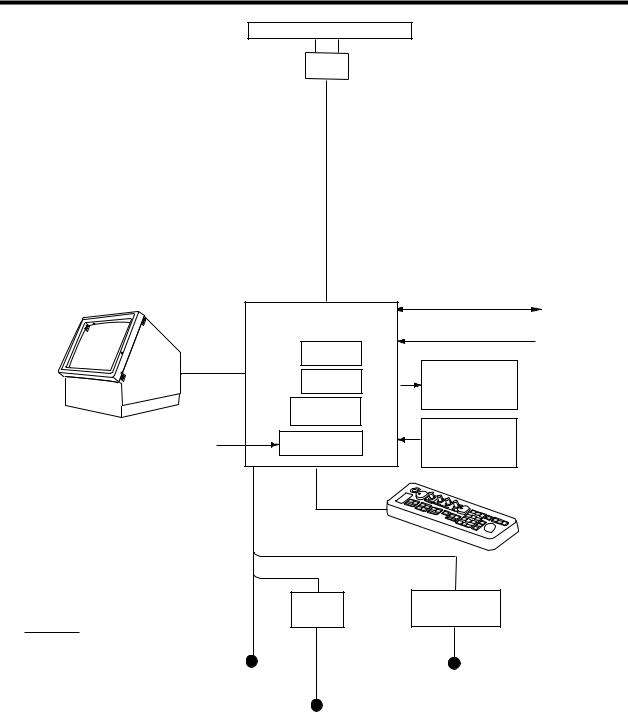
SYSTEM CONFIGURATION
ANTENNA UNIT
FR-2115-B: XN12AF-RSB-0074-062
XN12AF-RSB-0075-062
XN20AF-RSB-0074-062
XN20AF-RSB-0075-062
XN24AF-RSB-0074-062
XN24AF-RSB-0075-062
FR-2125-B: XN12AF-RSB-0074-063
XN12AF-RSB-0075-063
XN20AF-RSB-0074-063
XN20AF-RSB-0075-063
XN24AF-RSB-0074-063
XN24AF-RSB-0075-063
MONITOR |
|
IEC 61162-1 (Input/Output) Navigator |
|
RDP-124-M-ES |
PROCESSOR UNIT |
||
|
|
|
|
|
RPU-11 |
IEC 61162-1 (Input) |
Speed Log |
|
Alarm Kit |
|
|
|
|
|
|
|
OP03-156 |
|
|
|
ARPA Board |
Slave Display |
|
|
ARP-26 |
FMD-8010 |
|
|
|
|
|
|
Video Plotter |
|
|
|
RP-26 |
Performance |
|
|
Gyro Converter |
|
|
Gyrocompass |
Monitor |
|
|
GC-8 |
|
||
|
PM-30 |
|
|
|
|
|
|
AC spec or DC spec to be selected.
DC spec
Rectifier
RU-3424
Option
Ship's Mains 24/32 VDC or
100/110/115/220/230 VAC 1φ , 50/60 Hz
CONTROL UNIT
RCU-11
AC spec
Transformer Unit
RU-1803
440 VAC
1φ , 50/60 Hz
I/O Data Sentences
Input: GGA, RMA, RMB, RMC, GLL, ZDA, VBW, VHW, VTG, MWV, VWT, VWR, VDR, DPT, DBT, DBS, MTW, BWR, BWC, WPT, RTE
Output: RAOSD, RARSD, RATTM
vi

1. MOUNTING
1.1 Antenna Unit
1.1.1 Mounting considerations
∙The antenna unit is generally installed either on top of the wheelhouse or on the radar mast, on a suitable platform. Locate the antenna unit where there is a good all-round view.
∙No funnel, mast or derrick should be within the vertical beamwidth of the antenna in the bow direction, especially zero degrees ±5°, to prevent blind sectors and false echoes on the radar picture.
∙It is rarely possible to place the antenna unit where a completely clear view in all directions is available. Thus, you should determine the angular width and relative bearing of any shadow sectors for their influence on the radar at the first opportunity after fitting.
∙Locate the antenna of a direction finder clear of the antenna unit to prevent interference to the direction finder. A separation of more than two meters is recommended.
∙To lessen the chance of picking up electrical interference, avoid where possible routing the signal cable near other onboard electrical equipment. Also avoid running the cable in parallel with power cables.
∙A magnetic compass will be affected if placed too close to the antenna unit. Observe the following compass safe distances to prevent deviation of a magnetic compass: Standard compass, 1.70 m (FR-2115-B), 2.10 m (FR-2125-B), Steering compass, 0.90 m (FR-2115-B), 1.20 m (FR-2125-B).
∙Do not paint the radiator aperture, to ensure proper emission of the radar waves.
∙The signal cable run between the antenna and the display is available in lengths of 15 m (standard), 20 m, and 30 m. Whatever length is used it must be unbroken; namely, no splicing allowed.
∙The antenna base is made of cast aluminum. To prevent electrolytic corrosion of the antenna base, use the seal washers and corrosion-proof rubber mat.
∙Deposits and fumes from a funnel or other exhaust vent can adversely affect the aerial performance and hot gases may distort the radiator portion. The antenna unit must not be mounted where the temperature is more than 70°C.
∙Leave sufficient space around the unit for maintenance and servicing. See the antenna unit outline drawing for recommended maintenance space.
1-1
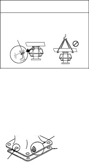
1.1.2 Assembling the antenna unit
The antenna unit consists of the antenna radiator and the antenna unit chassis, and they are packed separately. Fasten the antenna radiator to the antenna unit chassis as follows:
1.For the XN20AF, XN24AF, attach two guide pins to the underside of the antenna radiator.
2.Remove the waveguide cap from the radiator bracket. The cap may be discarded.
3.Coat the waveguide flange with anticorrosive sealant as shown in Figure 1-1.
10 mm O-ring
Hole for |
Hole for |
a guide pin |
a guide pin |
5 mm
Anticorrosive sealant
Figure 1-1 Coating the waveguide flange with anticorrosive sealant
4.Coat fixing holes for the antenna radiator with anticorrosive sealant.
5.Grease the O-ring and set it to the O-ring groove of the radiator flange.
6.Set the antenna radiator to the radiator bracket.
7.For the XN20AF, XN24AF, coat hex bolts (M8X40, slotted washer-head, 8 pcs.) with anticorrosive sealant and use them to loosely fasten the antenna radiator to the antenna unit chassis. For the XN12AF, coat hex bolts, flat washers and spring washers with anticorrosive sealant and use them to loosely fasten the antenna radiator to the antenna unit chassis.
8.For the XN20AF, XN24AF, remove two guide pins (inserted at step 1).
9.Tighten the bolts loosely fastened at step 7.
 CAUTION
Be sure to remove the guide pins.
Injury may result if the guide pins loosen and fall.
1-2
Antenna radiator
Guide pin (XN20AF, XN24AF only)
Waveguide
Radiator bracket
|
Hex bolt (M8X40), 8 pcs. |
|
(XN20AF, XN24AF only) |
|
Hex bolt (M8X35), 8 pcs. |
|
Flat washer |
|
Spring washer |
O-ring |
(XN12AF only) |
Figure 1-2 Fastening the radiator to the radiator bracket
1-3
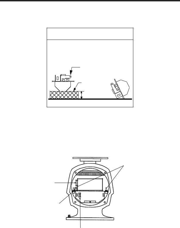
1.1.3 Fastening the antenna unit to the mounting platform
The antenna unit may be assembled before hoisting it to the mounting platform. However, do not lift the antenna unit by the radiator. Always hold the unit by its housing. When using a crane or hoist, lift the unit by the hoist rings which should be fastened to the bolt fixing covers of the antenna housing.
 CAUTION
DO NOT hoist the antenna unit by the radiator; hoist it by the hoist rings. (Be sure to remove rings after hoisting the antenna unit.)
Hoist |
|
NO! |
ring |
|
|
|
|
|
|
|
|
1.Construct a suitable mounting platform referring to the outline drawing at the back of the manual.
2.Drill four mounting holes of 15 mm diameter and one cable entry hole of about 50 mm diameter in the mounting platform.
3.Lay the rubber mat (supplied) on the mounting platform.
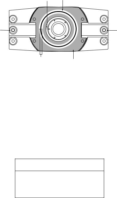
4.Place the antenna unit on the rubber mat orienting the unit so the bow mark on its base is facing the ship's bow.
Ground terminal
Rubber mat
Bow mark
Figure 1-3 Antenna unit, front view
5.Fasten the antenna unit to the mounting platform with four sets of M12X60 hex bolts, nuts, flat washers and seal washers (supplied).
6.Using hex bolt (M6X25), nut (M6) and flat washer (M6), establish the ground system on the mounting platform as shown in Figure 1-4. The location should be within 370 mm of the ground terminal on the antenna unit. Connect the ground wire (RW-4747, 370 mm, supplied) between the grounding point and ground terminal on the antenna unit. Coat the entire ground system with silicone sealant (supplied).
1-4
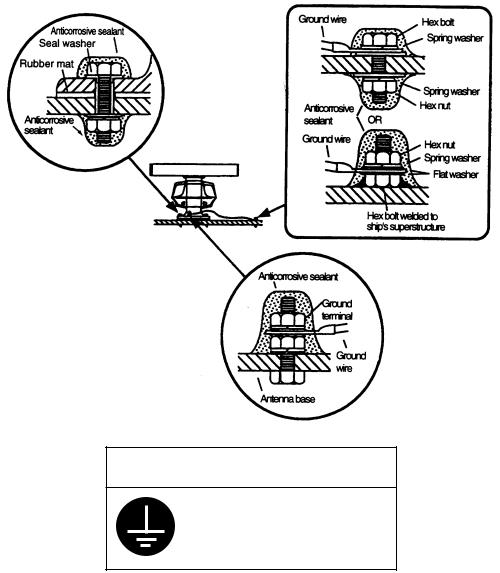
 CAUTION
Ground the equipment to prevent electrical shock and mutual interference.
Figure 1-4 How to mount the antenna unit
1-5
1.2 Processor Unit
1.2.1 Mounting considerations
When selecting a mounting location, keep in mind the following points:
∙The processor unit must be mounted horizontally.
∙DO NOT place any item on the top of the processor unit.
∙Locate the unit out of direct sunlight and away from heat sources because of heat that can build up inside the cabinet.
∙Locate the equipment away from places subject to water splash and rain.
∙Be sure the mounting location is strong enough to support the weight of the unit under the continued vibration which is normally experienced on the ship. If necessary reinforce the mounting location.
∙Determine the mounting location considering the length of the following cables:
a)Signal cable from the antenna unit
b)Power cable from the ship's mains
c)Monitor cable from the monitor
d)Control cable from the control unit
∙Leave sufficient space on the sides and rear of the unit to facilitate maintenance. Also, leave a foot or so of "service loop" in cables behind the unit for servicing ease.
∙A magnetic will be adversely affected if placed too close to the processor unit. Observe the following compass safety distances to prevent deviation of a magnetic compass: Standard compass, 1.70 m, Steering compass, 0.90 m.
1-6
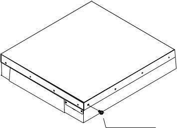
1.2.2 Mounting the processor unit
1.Drill four holes of 12 mm in diameter in the mounting location.
2.Unfasten 15 binding screws (M4) to remove the processor unit cover.
WARNING
Binding Screw
M4X8, 15 pcs.
Figure 1-5 Processor unit
3. Fasten the processor unit to the mounting location with four each of M10 bolts, nuts and washers, using the pipe box spanner (supplied). See the figure on the next page for location of fixing holes.
How to access the rear-left fixing hole
The rear-left fixing hole is hidden under the PTU board cover. To access it do the following:
a)Loosen five M3X8 screws at the top of the PTU board cover and two M4X8 screws at the front of the cover.
b)Grasp the knob on the cover and slide the cover toward the front of the unit to release it. How to access the front-right fixing hole
The front-right fixing hole is hidden beneath the RGB Board. To access it do the following:
a)Unfasten the M4X8 pan-head screw from the RGB board mounting plate.
b)Unfasten two pan-head screws (M3X10) fixing the M-card cover.
4.After mounting the unit, fasten the PTU board cover and RGB board mounting plate, and then close the processor unit.
1-7

*Screw (M3X8, 5 pcs.)
Slide forward.
Fixing hole (rear)
J106 |
|
* |
J105 |
Knob |
|
|
|
|
J104 |
|
* |
|
|
|
J103 |
|
|
* |
|
* |
Screw (M4X8, 2 pcs.) |
Fixing hole (front) |
J446 |
J466 |
J462 |
J465 |
 Pan-head
Screw M4X8
RP board |
mounting plate |
RGB board |
mounting plate |
RGB Board |
Pan-head Screw
M3X10
Figure 1-6 Processor unit, inside view
1-8
1.3 Monitor
The FR-2115-B/2125-B is available with or without a monitor. This section shows how to mount
the monitor supplied.
Mounting considerations
∙The monitor is designed to be mounted on a desktop.
∙Locate the monitor where it can be easily operated while viewing the screen and operating the control unit.
∙DO NOT place the monitor on the top of the processor unit.
∙Locate the monitor out of direct sunlight and away from heat sources because of heat that can build up inside the cabinet.
∙Locate the equipment away from places subject to water splash and rain.
∙Be sure the mounting location is strong enough to support the weight of the unit under the continued vibration which is normally experienced on the ship. If necessary reinforce the mounting location.
∙The length of the monitor cable which runs between the processor unit and the monitor is 10 m. Keep this distance in mind when selecting the mounting location for the monitor.
∙Leave sufficient space on the sides and rear of the unit to facilitate maintenance.
1-9

1.3.2 Mounting the monitor
1.Drill four holes of 12 mm in diameter in the mounting location, referring to the outline drawing for mounting dimensions.
2.Unfasten two M4X10 screws to dismount the monitor cover.
3.Unfasten two sets of M10 bolts, plain washers and spring washers at the front of the monitor to separate the monitor from the mounting base.
4.Pull the monitor forward about 4 centimeters and then lift if from the mounting base.
5.Fasten the mounting base to the mounting location with M10 bolts, nuts and washers (local supply), using the pipe box wrench supplied. Make sure there is 3mm protrusion under the nut.
6.Lay the monitor on the top of the mounting base, making sure the rear pin on the monitor is mated with the slit in the mounting base. Fix the mounting base with the two sets of bolts, and washers unfastened at step 3.
7.Fasten the monitor cover.
Plain Washer, M10, 2 pcs.
Spring Washer, M10, 2 pcs.
Hex Bolt M10X30, 2 pcs.
Monitor Cover
Pan-Head Screw
M4X10, 2 pcs.
Mounting Base
Hex Bolt. (M10)
 More than 3mm
Figure 1-7 Monitor
Pin
Hex Bolt
M10, 4 pcs.
Washer
 Slit
Slit
Mounting Base
1-10
1.4 Control Unit
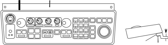
1.4.1 Mounting procedure
1.Attach rubber to feet to the bottom of the keyboard if the keyboard is not going to be permanently fixed. To fix the keyboard to a desired location, fasten the KB fixing plate to the keyboard and desired location with two upset screws (M5X10, supplied) and two tapping screws (φ 6.5, local supply) as below.
KB Fixing Plate
CONTROL UNIT |
φ 6.5 |
|
SIDE VIEW |
||
Tapping |
||
|
||
|
Screw |
|
KB Fixing |
M5X10 |
|
Plate |
||
|
Upset |
|
|
Screw |
Figure 1-8 How to attach KB fixing plate
2. Set KB dust cover (supplied) to the control unit.
1-11
2. WIRING
2.1Antenna Unit
 CAUTION
The magnetron in the transceiver module will demagnetize if it contacts ferrous material. When dismounting the transceiver module, lay it on its side or on top of non-ferrous material as shown below.
Transceiver module |
(magnetron inside) |
Non-ferrous |
block |
Height more than 5 cm
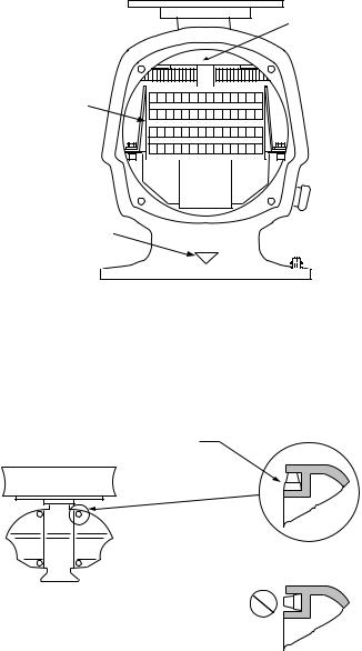
2.1.1 Mounting the antenna chassis
1.Open the antenna unit cover.
2.Disconnect plugs P611, P801 and P821 from the antenna unit.
3.Unfasten two bolts to dismount the transceiver module.
Fixing bolts
J611
J801
J821
Figure 2-1 Antenna unit, front view
2-1
4.Unfasten the four fixing bolts on the cable gland at the base of the antenna unit. Remove clamping ring, rubber gasket and washers.
From left: Clamping ring, washer, rubber gasket and washer
Signal cable
Figure 2-2 Antenna unit, front view, cover removed
5.Pass the signal cable through the cable entry hole in the antenna unit mounting platform. Trim the cable so about 80 cm of it protrudes past the cable gland.
6.Slide the clamping ring, washer, rubber gasket and washer onto the cable in that order.
7.Fabricate the signal cable as shown on page 2-4.
8.Referring to Figure 2-3, pass the outer and inner shields between the signal cable and the clamping ring. Fasten the cable gland.
Clamping
ring
Washers
Rubber gasket
Figure 2-3 Passing cable shields between cable and clamping ring
9.Connect the signal cable to the terminal board RTB801 by referring to the interconnection diagram. Leave slack in the coaxial wire to prevent breakage.
10.Bind cores of cables with cable ties.
11.Mount the transceiver module. Connect plugs P611, P801 and P821. Fasten the shield to the ground terminal on the transceiver module.
2-2
12.If the antenna is mounted 2° or more left of ship's bow, adjust the position of S901 so it becomes "on" (contact between #1 and #2 on pcb MP-3795). To access S901, open the bow side cover; S901 is above the drive gear.
S901
RTB801
Bow mark
1 |
2 |
3 |
4 |
5 |
6 |
7 |
8 |
9 |
10 11 12 13 14 |
15 16 17 18 19 |
20 21 22 23 24 25 26 27 28 |
||||||||
Figure 2-4 Antenna unit, front view
13.Confirm that all screws are tightened and all wiring is properly made. Coat waterproofing gasket, bolts and tapping holes of antenna unit with silicone grease. Check that the waterproofing gasket is seated as shown in Figure 2-5. Close the antenna unit cover.
Coat gasket with silicone grease.
DO NOT use silicone sealant.
CORRECT
WRONG
Figure 2-5 Correct seating of waterproofing gasket
2-3
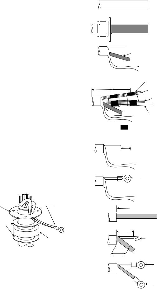
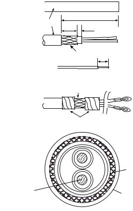
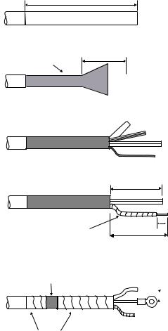
2.1.2 Fabricating signal cable S03-75
1.Remove the vinyl sheath by 450 mm.
2.Slide the clamping ring, washer, rubber gasket and washer onto the signal cable in that order.
3.Unravel the outer shield to expose the cores in the outer layer. Then, unravel the inner shield to expose the cores in the inner layer. Label all inner cores to aid in identification.
4.Attach EMI cores to all inner cores and all outer cores, and bind them with cable ties, etc. Note that there are two types of the EMI cores, thick and thin.
5.Trim each core (except coaxial wire) considering its location on the terminal board in the antenna unit.
6.Trim the inner and outer shields leaving 500 mm each. Twist shields together and attach crimp-on lug FV5.5-4 (blue, φ 4).
7.Remove insulation of each core by about 6 mm. Fix crimp-on lug FV1.25-3 (red, φ 3) to each core.
8.Fabricate the coaxial cable. Make the length 10 mm longer than the shield to prevent wire strain. Attach crimp-on lug FVD1.25-3 (red, φ 3) to coaxial cable.
VINYL SHEATH  450 mm

Inner shield
Under |
Cable tie |
|
70-130 mm |
||
100 mm |
||
Outer cores |
||
|
||
|
Inner cores |
500mm |
Coax cable |
= EMI cores
Outer cores: RFC-13 (thick) Inner cores: RFC-10 (thin)
6 mm
Crimp-on lug FV1.25-M3 (Red, φ 3)
Clamping ring
Washers 
Crimp-on lug |
|
FV5.5-5 |
|
(Blue, φ 4) |
2C-2V |
|
Rubber gasket
Figure 2-7 How to ground signal cable S03-75
Figure 2-6 How to fabricate signal cable S03-75
75 mm 

50 mm
 6 mm
6 mm
Fold four times
45 mm |
Cut here |
|
Crimp-on lug FVD1.25-3 (Red, φ 3)
Crimp-on lug FV1.25-3 (Red, φ 3)
2-4
2.2Processor Unit
Two cables are terminated at the processor unit: the signal cable S03-75 and the power cable. The signal cable comes with a connector preattached to it for connection to the processor unit. Fabricate the power cable as below.
2.2.1 Fabricating the AC power cable
1.Remove the vinyl sheath by 80 mm. Cut off jute tape wrapped around the armor. Unravel the armor to expose the cores by about 35 mm.
2.Remove insulation of cores by about 10 mm. Fix crimp-on lugs to the cores and armor.
3.Cover the armor with vinyl tape, leaving the portion which will lie inside the cable clamp untaped.
(a)  DPYCY-3.5
Approx. 80 mm |
|
Vinyl sheath |
|
40mm |
5 mm |
(b) |
|
|
Armor 10 mm |
(c)
Clamp here.
(d)
Taping
|
Armor |
Core |
Vinyl sheath |
S = 3.5 mm2 |
φ = 2.4 mm
(sectional view)
Figure 2-8 Fabricating power cable DPYCY-3.5
2-5
2.2.2 Fabricating the DC power cable (CVV-S 8X2C, option)
1.Remove the vinyl sheath by 100 mm.
2.Unravel the braided shield 60 mm from end of cable.
3.Remove the jute tape and inclusion from cable.
4.Expose the cores by 50 mm.
5.Expose the shield by 60 mm. Tape the shield, leaving 10 mm exposed.
6.Remove the sheath of cores by 10 mm. Attach crimp-on lug type 8NK4 to the cores and crimp-on lug type FV5.5-4 (yellow) to the shield.
7.Tape the cable as shown in the figure below. Fasten the shield to screw (M4) on the cable clamp.
100 mm
CVV-S 8X2C
60 mm
Braided Shield

 Core
Core
 Jute Tape
 Inclusion
|
50 mm |
Taping |
10 mm |
|
|
|
60 mm |
Fasten cable clamp here.

 Crimp-on Lug
 8NK4
8NK4 
 Crimp-on Lug
FV5.5-4
Taping
Figure 2-9 Fabricating power cable CVV-S 8X2C
2-6
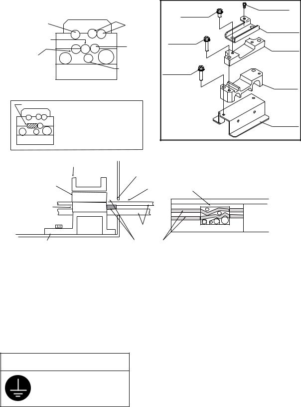
2.2.3 Leading in cables to the processor unit
Cables are led in to the processor unit through the cable clamp at the rear of the unit. Use the
shielding foam (supplied) as below to protect against noise radiation.
|
|
|
Pan-head screw |
|
|
|
Hex bolt |
M4X8 |
|
|
|
|
||
Nav equipment |
Slave display |
M5X12 SUS |
|
|
(Gyro, etc.) |
2 pcs |
(D) Rear clamp |
||
|
|
plate |
||
|
|
|
||
Navigator* |
|
Hex bolt |
(C) Signal clamp |
|
|
Control |
|||
|
M5X35 SUS |
(Aluminum) |
||
Log* |
unit |
2 pcs |
|
|
ANT |
|
|
||
PWR |
|
|
||
|
Monitor |
Hex bolt |
|
|
|
|
|
||
|
|
M5X35 SUS |
(B) Power clamp |
|
Cable position in cable clamp |
2 pcs |
|||
(Aluminum) |
||||
|
||||
(Processor unit, rear view) |
|
|
||
Rubber plug |
|
|
|
|
* When no log or nav equipment is |
|
(A) Rear clamp |
||
installed, insert rubber plug |
|
|||
(supplied) to the left of keyboard |
(Construction of |
base |
||
|
||||
cable to hold the cable in place. |
|
|||
cable clamp) |
|
|||
|
|
|
||
(D) Rear clamp plate
Make sure shielding foam contacts rear chassis.
(C) Signal cable |
|
Rear cable entrance |
(Aluminum) |
|
|
|
|
|
|
|
|
(B) Power clamp (Aluminum)
|
Cable |
(A) Rear clamp base |
Shielding foam |
|
(Processor unit, rear view)
(Processor unit, right-hand side view)
Figure 2-10 Cable clamp position
•Place shielding foam between cables, and then attach foam to aluminum clamps.
•Fill unused clamp holes with shielding foam.
•Connect a ground wire between the earth terminal on the processor unit and ship's superstructure.
 CAUTION
Ground the equipment to prevent electrical shock and mutual interference.
2-7
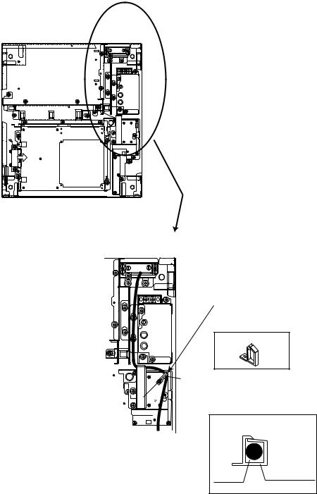
2.3Monitor
2.3.1 Connection of monitor cable inside processor unit
The monitor cable (a monitor cable comes with FURUNO-supplied monitor) runs between the RGB Board (inside the processor unit) and the monitor. Route it inside the processor unit as below. Connect the cable to J2 on the RGB Board. If a converter adaptor is used it may be necessary to route the cable differently than shown. In any case be sure the cable does not touch the TX-HV Board.
EXPLODED VIEW
TX-HV Board (Underneath the plate)
Locking Wire Saddle
Locking Wire Saddle LWS-2H
with M3X10 Pan-head Screw
45° 
Cable inside Locking Wire |
|
Saddle |
|
|
Locking Wire |
Cable |
Saddle |
Figure 2-11 Processor unit, inside view
2-8
Loading...