


 Loading...
GPS NAVIGATOR
GP-150

9-52 Ashihara-cho,
Nishinomiya 662-8580, JAPAN
Telephone : 0798-65-2111
Fax |
: 0798-65-4200 |
All rights reserved. |
Printed in Japan |
Pub. No. OME-44400
( HIMA ) GP-150
The paper used in this manual is elemental chlorine free.
FURUNO Authorized Distributor/Dealer
FIRST EDITION : FEB. 2006
*00015801400*
*00015801400*
* 0 0 0 1 5 8 0 1 4 0 0 *
*OME44400A00*
*OME44400A00*
* O M E 4 4 4 0 0 A 0 0 *

IMPORTANT NOTICE
•This manual is intended for use by native speakers of English.
•No part of this manual may be copied or reproduced without written permission.
•If this manual is lost or worn, contact your dealer about replacement.
•The contents of this manual and equipment specifications are subject to change without notice.
•The example screens (or illustrations) shown in this manual may not match the screens you see on your display. The screen you see depends on your system configuration and equipment settings.
•FURUNO will assume no responsibility for the damage caused by improper use or modification of the equipment by an unauthorized agent or a third party.
•Store this manual in a convenient place for future reference.
i

 SAFETY INSTRUCTIONS
 WARNING
Do not open the cover of the equipment.
This equipment uses high voltage electricity which can shock, burn or cause death. Only qualified person-
nel should work inside the equipment.
Do not dissasemble or modify the equipment.
Fire, electrical shock or serious injury can result.
Immediately turn off the power at the ship’s mains switchboard if water or foreign object falls into the equipment or the equipment is emitting smoke or fire.
Continued use of the equipment can cause fire, electrical shock or serious injury.
 CAUTION
Use the correct fuse.
Use of the wrong fuse can cause fire or equipment damage.
No single navigation aid (including this unit) should ever be relied upon as the exclusive means for navigating your vessel.
The navigator is responsible for checking all aids available to confirm his position. Electronic aids are intended to assist, not replace, the navigator.
Use of an autopilot with this unit, to provide automatic steering to destination, does not eliminate the need to maintain a watch.
Always maintains a vigilant watch to prevent collision or grounding.
WARNING Label attached
 WARNING
To avoid electrical shock, do not remove cover. No user-serviceable parts inside. - -
-- - - - - - - - - - - - - - - - - - - - - - - - - - - -
-- - - - - - - - - - - - - - - - - - - - - - - - - - - -
-- - - - - - - - - - - - - - - - - - - - - - - - - - - -
Name: |
Warning Label (1) |
Type: |
86-003-1011-1 |
Code No.: 100-136-231
ii
TABLE OF
CONTENTS
|
|
|
.............................................FOREWORD |
iv |
|
SYSTEM CONFIGRATION ........................ |
v |
|
1. OPERATIONAL OVERVIEW |
|
|
1.1 |
Control Description ......................... |
1-1 |
1.2 Turning On and Off the Power ...... |
1-2 |
|
1.3 Adjusting Display Contrast and |
|
|
|
Brilliance.......................................... |
1-3 |
1.4 |
Selecting the Display Mode ............ |
1-3 |
1.5 |
Icons ............................................... |
1-6 |
2. TRACK |
|
|
2.1 |
Enlarging/Shrinking the Display ...... |
2-1 |
2.2 |
Selecting Display Orientation.......... |
2-1 |
2.3 |
Shifting the Cursor .......................... |
2-1 |
2.4 |
Shifting the Display ......................... |
2-2 |
2.5 |
Centering Cursor Position............... |
2-2 |
2.6 |
Centering Own Ship's Position........ |
2-2 |
2.7 |
Stopping/Starting Plotting and |
|
|
Recording of Track......................... |
2-2 |
2.8 |
Erasing Track.................................. |
2-3 |
2.9 |
Selecting Track Plotting Interval...... |
2-4 |
2.10 Apportioning the Memory .............. |
2-5 |
|
2.11 Selecting Bearing Reference ........ |
2-6 |
|
3. MARKS |
|
|
3.1 |
Entering/Erasing Marks................... |
3-1 |
3.2 |
Selecting Mark Shape..................... |
3-2 |
3.3 |
Connecting Marks |
|
|
(selecting mark connection line) .... |
3-2 |
3.4 |
Entering Event Marks...................... |
3-3 |
3.5 |
Selecting Event Mark Shape........... |
3-3 |
3.6 |
Entering the MOB Mark .................. |
3-4 |
4. NAVIGATION PLANNING |
|
|
4.1 |
Registering Waypoints .................... |
4-1 |
4.2 |
Editing Waypoints ........................... |
4-5 |
4.3 |
Deleting Waypoints ......................... |
4-5 |
4.4 |
Registering Routes ......................... |
4-6 |
4.5 |
Deleting Route Waypoints............... |
4-7 |
4.6 |
Replacing Route Waypoints............ |
4-7 |
4.7 |
Deleting Routes .............................. |
4-8 |
5. STARTING FOR DESTINATION |
|
|
5.1 |
Setting Destination.......................... |
5-1 |
5.2 |
Canceling Destination..................... |
5-5 |
5.3 |
Erasing Route Waypoints (flags)..... |
5-6 |
5.4 |
Finding Range and Bearing Between |
|
|
Two Points..................................... |
5-7 |
6. SETTING UP VARIOUS DISPLAYS |
|
|
6.1 |
Selecting Data to Display on the |
|
|
Data Display .................................. |
6-1 |
6.2 |
Selecting Position Format ............. |
6-2 |
6.3 |
Demo Display ................................. |
6-4 |
7. ALARMS
7.1 Arrival Alarm, Anchor Watch Alarm . 7-1
7.2 |
Cross Track Error (XTE) Alarm ....... |
7-2 |
7.3 |
Ship’s Speed Alarm ........................ |
7-3 |
7.4 Trip Alarm ....................................... |
7-3 |
|
7.5 |
Water Temperature Alarm............... |
7-4 |
7.6 |
Depth Alarm.................................... |
7-4 |
7.7 |
DGPS Alarm ................................... |
7-4 |
8. MENU SETTINGS |
|
|
8.1 GPS Menu...................................... |
8-1 |
|
8.2 |
Selecting Units of Measurement..... |
8-4 |
8.3Mark, Character Size and Brilliance8-5
8.4Settings for Connection of
|
Navigator....................................... |
8-6 |
8.5 |
Receiving Data from Personal |
|
|
Computer................................... |
8-8 |
8.6 |
WAAS/DGPS Settings .................. |
8-10 |
8.7Displaying GPS Monitor Displays . 8-12
9.MAINTENANCE & TROUBLESHOOTING
9.1 |
Clearing the Memory ...................... |
9-1 |
9.2 |
Preventive Maintenance ................. |
9-2 |
9.3 |
Error Messages .............................. |
9-2 |
9.4 Troubleshooting .............................. |
9-4 |
|
9.5 |
Diagnostic Tests ............................. |
9-5 |
APPENDIX |
|
|
MENU TREE ........................................ |
A-1 |
|
DIGITAL INTERFACE |
|
|
(IEC 61162-1 EDITION 2 (2000-07)) .... |
A-4 |
|
TIME DIFFERENCES......................... |
A-21 |
|
GEODETIC CHART LIST ................... |
A-22 |
|
LORAN C CHAINS ............................. |
A-23 |
|
DECCA CHAINS................................. |
A-24 |
|
PARTS LIST ....................................... |
A-25 |
|
SPECIFICATIONS ............................... |
SP-1 |
|
INDEX |
................................................... |
IN-1 |
iii

FOREWORD
A Word to GP-150 Owners
Congratulations on your choice of the FURUNO GP-150 GPS Navigator. We are confident you will see why the FURUNO name has become synonymous with quality and reliability.
For over 50 years FURUNO Electric Company has enjoyed an enviable reputation for innovative and dependable marine electronics equipment. This dedication to excellence is furthered by our extensive global network of agents and dealers.
Your navigator is designed and constructed to meet the rigorous demands of the marine environment. However, no machine can perform its intended function unless operated and maintained properly. Please carefully read and follow the recommended procedures for operation and maintenance.
We would appreciate hearing from you, the end-user, about whether we are achieving our purposes.
Thank you for considering and purchasing FURUNO equipment.
Features
The GP-150 GPS Navigator is a totally integrated GPS receiver and video plotter consisting of a display unit and an antenna unit. The high sensitivity receiver tracks up to 12 satellites simultaneously. An 8-state Kalman filter ensure optimum accuracy in determination of vessel position, course and speed.
In most cases the operator needs to do is to turn on the power to find position.
The main features of the GP-150 are
•Comprehensive navigation data displays
•Storage for 999 waypoints and 30 routes
•Alarms: Waypoint Arrival, Anchor Watch, Cross-track Error, Ship's Speed, Water Temperature, Depth and Trip
•Man overboard feature records latitude and longitude coordinates at time of man overboard and provides continuous updates of range and bearing to that point.
•DGPS capability - with built-in DGPS beacon kit accepts DGPS correction data from external DGPS beacon receiver
•Menu-driven operation
•Bright 122 x 92 mm LCD with temperature compensated tone and brilliance adjustment
•Power consumption is a low 10 W.
•Provision for connection of autopilot (option) - steering data output to autopilot
•Digital display of water temperature and depth with connection of echo sounder (with NMEA input)
•Memory stores 2,000 points of track and marks.
•"Highway" display provides perspective view.
•Position may be shown in latitude and longitude or LOP (Loran or Decca).
•Four connectors for optional equipment two IEC 61162-1/NMEA 0183 I/O, one IEC 61162-1/NMEA 0183 (or log) output and one DGPS for personal computer I/O
•Fully meets the following regulation: IMO MSC. 112(73) and IEC 61108-1.
Program No.
2051518-01.xx (January, 2006)
iv
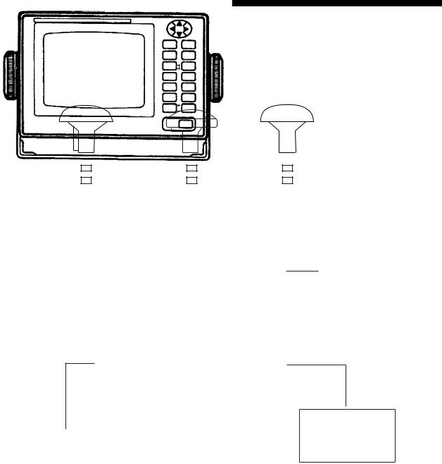
SYSTEM CONFIGURATION
Antenna Unit GPA-018S*
Antenna Unit GPA-019S* |
|
|
|
Antenna Unit GPA-017S** |
||||||
|
|
|
|
|
|
|
|
|
|
|
|
|
|
|
|
|
|
|
|
|
|
|
|
|
|
|
|
|
|
|
|
|
|
|
|
|
|
|
|
|
|
|
|
|
|
|
|
|
|
|
|
|
|
|
|
|
|
|
|
|
|
|
|
|
|
|
|
|
|
|
|
|
|
|
|
|
Radar, Echosounder,
Autopilot etc.
Display Unit
DGPS Beacon
12-24VDC Receiver
GR-80**
*: w/internal beacon receiver **: w/o internal beacon receiver
CATEGORY OF UNITS
Unit |
Category |
ANTENNA UNIT |
Exposed to weather |
DISPLAY UNIT |
Protected from weather |
v
This page intentionally left blank.
vi
1. OPERATIONAL OVERVIEW
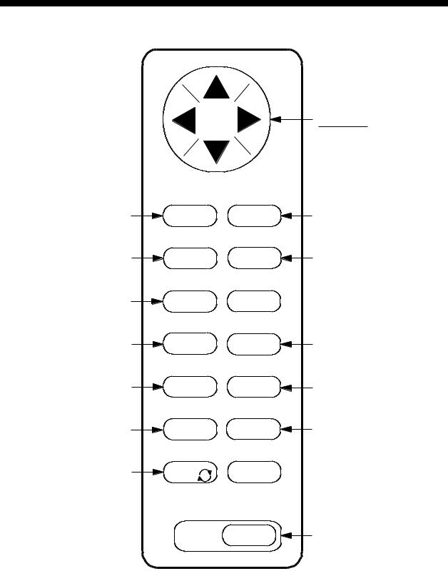
1.1Control Description
Opens/closes menu; |
MENU |
|
ESC |
|
|
quits current operation. |
|
|
|
|
|
Selects display mode. |
DISPLAY |
|
SEL |
1 |
|
Registers waypoints |
WPT |
2 |
RTE |
||
and routes. |
|
|
Inscribes mark on |
MARK 3 |
|
the display. |
|
|
Cursor pads Shift display and cursor.
NU/CU
ENT Selects display orientation; registers selections on menus.
EVENT
MOB 6 Inscribes event mark at ship’s position; marks man overboard position
GOTO 7  Sets destination.
PLOT
ON/OFF8 Turns recording and plotting of ship’s track on/off.
Enlarges display. |
ZOOM |
4 |
ZOOM |
Shrinks display. |
IN |
OUT 9 |
Centers ship’s position/cursor |
CENTER |
|
5 |
||
position. |
||
|
||
Adjusts display contrast |
TONE |
|
and brilliance; |
|
|
changes latitude/longitude |
|
|
coordinate. |
|
CURSOR ON/OFF 0
CLEAR
POWER
Turns cursor on/off.
 Deletes waypoints and marks; clears wrong data; silences audible alarm.
Turns power on/off.
Figure 1-1 Control Panel
1-1
1. OPERATION
1.2Turning On and Off the Power
The GP-150 takes about 90 seconds to find position when turned on for the very first time. Thereafter it takes about 12 seconds to find position each time the power is turned on.
Turning on the power
Press the POWER key.
The unit tests the PROGRAM MEMORY, SRAM and battery for proper operation and shows the results on the display. If equipped with the internal beacon receiver, "BEACON RCVR INSTALLED" appears at the bottom of the display. The unit starts up with the last used display mode.
PROGRAM MEMORY = OK
SRAM |
= OK |
Internal Battery |
= OK |
BEACON RCVR INSTALLED |
|
|
DATA 3 : DATA OUTPUT |
|
|
Several seconds |
|
GPS receiving |
|
condition |
|
later |
|
|
34° 23.456· N 135° 45.678· E |
D3D 100m |
|
SAFE |
||
30 |
|
BRG |
|
|
|
[01] |
|
---° |
|
|
|
|
|
COG |
40 |
50 |
7° |
|
|
|
H |
|
RNG |
|
|
123 nm |
20 |
|
SOG |
|
12.3 kt |
|
2nm |
|
|
WGS84 |
|
|
Figure 1-2 Appearance of display when turning on the power
When turning on the power the following occurs:
12 seconds after turning on the power, accurate position (in latitude and longitude) appears on the display.
If position could not be found, "NO FIX" appears at the GPS receiving condition window. When PDOP (Position Dilution Of Precision) value exceeds 6 in the 3D mode or HDOP (Horizontal Dilution Of Precision) value exceeds 4 in the 2D mode, "DOP" appears to indicate abnormal fixing and the position indication could not be updated.
When the satellite signal is being received normally, one of the indications shown in Table 1-1 appears depending on equipment setting and GPS receiver state.
Table 1-1 GPS receiver indication
Indication |
Meaning |
2D |
2D |
3D |
3D |
D2D |
Differential 2D |
D3D |
Differential 3D |
W2D |
WAAS 2D |
W3D |
WAAS 3D |
Note 1: When PDOP value exceeds 6 in the 3D mode, the position fixing method is automatically changed to 2D.
Note 2: The "DEMO" icon appears when the display is in the demonstration mode. To return to normal mode, turn off the power and turn it on while pressing and holding down the
NU/CU ENT key.
Turning the power off
Press the POWER key.
The next time you turn on the power the unit starts up with the last used display mode.
1-2
1.3Adjusting Display Contrast and Brilliance
1)Press the TONE key. The display shown in Figure 1-3 appears.
|
|
|
|
|
|
|
|
[-] |
[+] |
|
|
|
|
|
|
|
|
|
|
|
|
|
|
Tone: |
|
|
|
|
|
||
17 |
(0~31) |
|
|||||
Brilliance: |
|
|
|
|
|||
7 (0~7) |
|
||||||
MENU : Escape
Figure 1-3 Screen for adjustment of display contrast and brilliance
2)To adjust contrast, press  or
or  . Current setting and setting range (0-31) are shown to the right of "
 ".
".
To adjust brilliance, press  or
or  . Current setting and setting range (0-7) are shown to the right of "
 ".
".
Note 1: Operate cursor keys within 10 seconds after pressing the TONE key. Otherwise, the screen for adjustment of contrast and brilliance will be cleared.
Note 2: If the display is turned off with minimum tone the display will be blank at the next power up. When this occurs press the TONE key continuously to adjust tone.
1. OPERATION
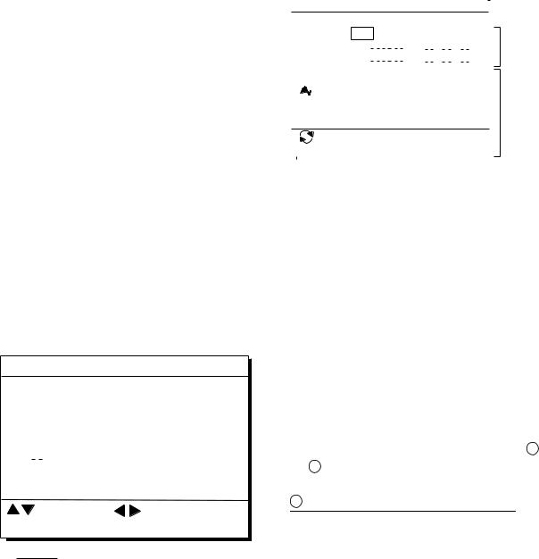
1.4Selecting the Display Mode
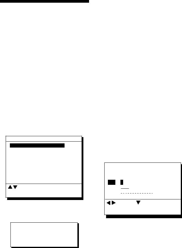
1)Press the DISPLAY SEL key. The display shown in Figure 1-4 appears.
Select Display
Plotter 1
Plotter 2
Highway
Navigation
Data
(DATUM: WGS-84)
: Select
MENU : Escape
*Shows currently selected geodetic chart datum.
Figure 1-4 Screen for selection of display mode
2)Press the DISPLAY SEL key,  or
or  to select display mode. (When the DISPLAY SEL key is pressed, the display mode changes in sequence shown below.) Selected display mode appears.
 Plotter 1
 Plotter 2
  Highway
Data  Navigation
Sample displays of each display mode are shown in the figures on the next several pages.
1-3
1. OPERATION
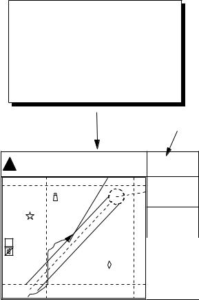
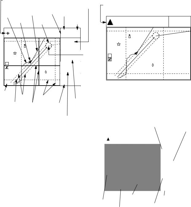
Plotter 1 display |
Plotter 2 display |
Cursor position data, |
|
Bearing from own ship |
||
when cursor is on |
|
|||
|
|
RAIM |
to destination waypoint |
|
Own ship's |
Course |
GPS receiving |
||
reliability* |
||||
track |
bar |
condition |
||
|
||||
Own ship |
Alarm |
Distance for |
||
mark |
|
|||
|
range |
|||
|
RAIM reliability |
|||
|
|
|||
34° 23.456´ N 135° 45.678´ E |
D3D 100m |
|
|
SAFE |
|
||
|
|
|
|
|
30 |
BRG |
|
|
|
|
|
|
[01] |
44° |
|
|
|
|
|
|
|
COG |
Waypoint |
40 |
50 |
32° |
|
H |
|
BRG TO + |
|
|
|
123° |
|
|
20 |
RNG TO + |
|
|
11.5 nm |
|
|
WGS84 |
|
|
|
2.00 nm |
|
|
|
Horizontal |
Course |
|
range |
Grid |
|
|
width |
Course over ground |
|
|
Course Cursor
Range
from own ship to cursor
Ship's position appears when cursor is off
34° 23.456´ N 135° 45.678´ E |
D3D 100m |
|
SAFE |
||
|
30 |
|
|
[01] |
|
40 |
50 |
|
|
|
|
H |
|
|
|
20 |
|
WGS84 |
|
|
2.00 nm |
|
|
Figure 1-6 Plotter 2 display |
||
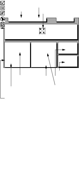
Highway display
Bearing from own |
Bearing from own ship to |
ship to cursor |
destination waypoint |
|
*: For RAIM function, refer to page 8-1.
Figure 1-5 Plotter 1 display
Position |
Course over ground |
|
|
|
|
|
|
|
|
|
|
|
|
|
|
|
D3D 100m |
|
|
|
|
|
|
|
|
|
|
|
34° 23.456´ N 135° 45.678´ E |
|
|
|||
|
|
|
SAFE |
|
|||
|
|
|
|
|
|
|
|
|
|
|
|
|
|
BRG |
|
|
|
|
|
|
|
34° |
|
|
|
|
|
|
|
COG |
|
|
|
|
|
|
|
45° |
|
|
|
|
|
|
|
RNG |
|
|
|
|
|
|
|
0.35nm |
|
|
|
|
|
|
|
SOG |
|
|
WGS84 |
|
|
12.3 kt |
|
||
|
|
|
|
|
|
|
|
|
|
|
Own ship mark |
|
|
Speed over ground |
|
North mark |
Range from own ship to |
||||||
|
|
Cross track error scale |
|||||
|
|
destination waypoint |
|||||
Figure 1-7 Highway display
1-4

|
1. OPERATION |
Navigation display |
2) With autopilot connection, automatic |
1) No autopilot connection |
mode |
|
|
|
|
|
|
|
|
|
|
TO; 012 |
|
|
D3D |
|
100m |
|
Cross track |
|
Bearing from own |
|
|
|
SAFE |
|
|
|||||
|
error meter |
|
ship to destination |
|
|
E |
|
SOG |
|
|
||||
|
|
Bearing |
|
waypoint |
|
|
|
|
|
|
12.3 kt |
|||
Destination |
|
|
|
|
|
Speed over ground |
|
|
||||||
waypoint no. |
scale |
|
|
Velocity To |
|
N |
|
|
VTD |
|
|
|||
|
|
|
Destination |
|
|
|
|
|
||||||
|
|
|
|
|
|
|
BRG: |
|
|
|
||||
|
|
|
|
|
|
|
|
|
|
|
10.3 kt |
|||
TO; 012 |
|
|
|
|
|
D3D |
100m |
|
63° |
|
||||
|
|
|
|
|
SAFE |
|
|
COG: |
S |
RNG |
|
|
||
|
|
|
|
|
E |
|
SOG |
|
|
123° |
|
|
||
|
|
|
|
|
|
|
|
0.1nm 123 nm |
||||||
|
|
|
|
|
|
|
12.3kt |
0.1nm |
||||||
|
N |
|
|
|
|
|
VTD |
|
|
|
|
TRIP |
|
|
|
|
BRG |
|
|
|
|
|
|
|
|
|
|
||
|
|
|
|
|
|
10.3kt |
Auto Pilot |
Hdg |
Str |
|
|
|||
|
|
63° |
|
|
|
789 |
nm |
|||||||
|
|
|
|
|
Auto |
123° |
P 23° |
|||||||
|
|
COG |
|
|
S |
|
RNG |
|
|
|||||
|
|
123° |
|
|
|
|
|
|
|
|
||||
0.1nm |
|
|
0.1nm 123nm |
Auto mode |
|
|
|
|
|
|||||
|
|
|
|
|
|
|
TRIP |
|
Heading |
SteeringRudder angle |
|
|
||
|
15 |
|
|
|
3D |
|
|
|
|
|
||||
ETA |
TTG |
|
|
|
|
|
|
|
|
|
||||
|
|
789nm |
|
|
P: Port |
|
|
|
||||||
|
|
|
|
|
|
|
|
|
|
|||||
|
23:45' |
|
17H 45M |
|
|
|
|
S: Starboard |
|
|
||||
|
|
|
|
|
|
|
Trip |
|
|
|
|
|
|
|
Estimated Time of |
|
|
distance |
|
Figure 1-9 Navigation display, with autopilot |
|||||||||
Time To Go |
|
|
|
|||||||||||
Arrival (15th23:45) |
|
|
|
|||||||||||
(3days17hrs45min) |
|
connection, automatic mode |
|
|
||||||||||
|
|
|
|
|
|
|||||||||
|
|
Cross track |
|
|
|
|
|
|
|
|||||
|
|
|
|
|
Range from own |
|
|
|
|
|
|
|||
Cross track |
error indication |
|
|
|
|
|
|
|
||||||
|
ship to destination |
|
|
|
|
|
|
|||||||
error scale |
|
|
|
|
|
|
|
|
|
|
|
|||
|
|
|
|
|
waypoint |
|
|
|
|
|
|
|
||
|
|
|
|
|
|
|
|
|
|
|
|
|
|
|
|
|
|
|
|
|
|
|
|
3) Autopilot connection, modes other than |
|||||
|
|
|
|
Waypoint |
|
|
|
automatic mode (manual, nav, etc.) |
|
|
||||
|
|
|
|
|
|
|
|
|
|
|
||||
|
|
|
|
|
|
|
|
|
TO; - - - |
|
|
D3D |
100m |
|
|
|
|
|
|
|
|
|
|
E |
|
SAFE |
|
|
|
|
|
|
|
|
|
|
|
|
|
|
SOG |
|
|
|
|
|
|
|
|
|
|
|
|
|
|
|
12.3 kt |
||
|
|
|
|
|
|
|
|
|
N |
|
|
VTD |
|
|
|
|
|
|
|
|
|
|
|
|
BRG: |
|
|
|
|
|
|
|
|
|
|
|
|
|
|
|
10.3 kt |
|||
|
|
|
|
|
|
|
|
|
|
63° |
|
|||
|
|
VTD |
|
|
SOG |
|
|
|
|
COG: |
S |
AP CSE |
|
|
|
|
|
|
|
|
|
|
|
123° |
|
||||
|
|
|
|
|
|
|
|
|
0.1nm |
0.1nm 123° |
|
|||
Auto Pilot |
Hdg |
TRIP |
Str |
||
Man |
123° |
P 23° 789nm |
Figure 1-8 Navigation display, no autopilot connection
Man: Manual mode |
Heading |
Steering |
|
|
|
Nav: Nav mode |
|
Autopilot-set |
Other:--- |
|
|
|
course |
|
|
|
Figure 1-10 Navigation display, with autopilot connection, modes other than
the automatic mode
1-5
1. OPERATION
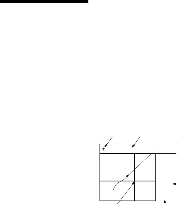
Data display
Refer to Chapter 6 for user-defined window setting. The ZOOM icon can be displayed by pressing the CURSOR ON/OFF key.
|
|
|
Position in latitude and |
|
|
|
|
|
|
||
|
|
|
longitude or LOPs |
U: UTC |
|
|
|
|
|
|
|
|
Fixing date and time* |
|
|
J: JST |
|
|
|
|
|
Zoom icon |
S: Ship's time |
|
|
|
|
||
SEP 12, 2005 23:59'59" U |
D3D |
100m |
||
SAFE |
|
|||
POSITION |
12° 23.456' N |
|
||
|
|
|||
123° 23.456' E |
|
|||
WGS84 |
|
|
|
|
RNG |
|
BRG |
TO : 001 |
|
31.23 nm |
223.4° |
|
MARINE |
|
|
POINT1 |
|||
SOG |
|
COG |
NEXT : 002 |
|
12.3 |
kt |
123.4° |
|
MARINE |
|
POINT2 |
|||
|
|
|||
|
|
|
Next destination waypoint |
|
User-defined |
User-defined |
Current destination waypoint |
||
display data #1 |
|
|
||
display data #4 |
|
|
||
|
|
|
|
|
User-defined |
|
User-defined |
|
|
|
display data #3 |
|||
display data #2 |
|
|||
|
|
|
|
|
User-defined |
|
|
|
|
display window |
|
|
|
|
Figure 1-11 Data display mode
*: "- -" appears until calculating position after turning on the power. If fixing error occurs this indication stops.
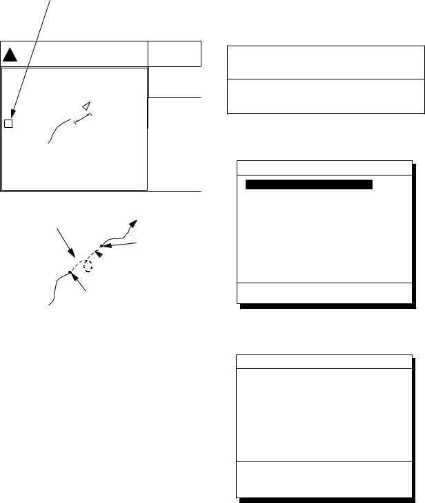
1.5Icons
Various icons appear on the left-hand side of display to alert you to equipment status.
:L/L position offset applied.
:Track recording is suspended.
:Alarm is violated.
:North mark.
:Demonstration display.
1-6
2. TRACK
2.1Enlarging/Shrinking the Display
You may enlarge and shrink the display on the Plotter 1, Plotter 2 and Highway displays, with the ZOOM IN and ZOOM OUT keys. The horizontal range is available among 0.25, 0.5, 1, 2, 4, 8, 16, 32, 64, 128 and 192 nautical miles for Plotter 1 and Highway, and 0.36, 0.71, 1.42, 2.84, 5.69, 11.38, 22.76, 45.51, 91.02, 182.04, 273.07 nautical miles for Plotter 2 display.
The ZOOM IN key enlarges the display and the ZOOM OUT key shrinks it. Each time a zoom key is pressed the display range appears at the center of the display for about one seconds.
2.2Selecting Display Orientation
Display orientation can be selected on the Plotter 1 and Plotter 2 displays, with the NU/CU ENT key. Two display orientations are available: north-up and course-up.
North-up display
In the north-up display, true north (0°) is at the top of the display. Own ship moves on the display in accordance with true motion. Land is stationary.
Course-up display
Destination set
The destination is at the top of the display and the north mark ( ) appears at the left side of the display.
Destination not set
Ship's course is upward on the screen at the moment the course-up mode is selected. The north mark appears at the left side of the display.
2.3Shifting the Cursor
The cursor can be shifted with the cursor pads.
1)Press the CURSOR ON/OFF key to turn on the cursor.
2)Press the cursor pads.
The cursor moves in the direction of the cursor pads pressed. When the cursor reaches the edge of the display, the display shifts in the direction opposite.
Data and cursor state
Cursor state determines what data are shown on the display.
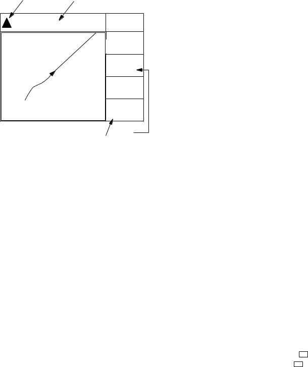
Cursor turned on, cursor data
Cursor position is displayed in latitude and longitude or LOPs (depending on menu setting) at the top of the display. The range and bearing from own ship to the cursor appear at the right hand side of the display, when in the Plotter 1 display.
Cursor mark |
Cursor position in |
latitude and longitude
34° 23.456´ N 135° 45.678´ E |
D3D 100m |
|
SAFE |
||
|
||
|
BRG |
|
|
234° |
|
|
COG |
|
|
345° |
|
|
BRG TO + |
|
|
123° |
|
|
RNG TO + |
|
WGS84 |
11.5nm |
|
2.0 nm |
Cursor |
|
|
Range from own |
||
|
ship to cursor |
|
Bearing from own ship to cursor
Figure 2-1 Data displayed when the cursor is turned on
2-1
2. TRACK
Cursor turned off
Ship's position (in latitude and longitude or LOPs), speed and course appear on the display.
Own ship |
Own ship position |
mark |
in latitude and longitude |
34° 23.456´ N 135° 45.678´ E |
D3D 100m |
|
SAFE |
||
|
||
|
BRG |
|
|
234° |
|
|
COG |
|
|
345° |
|
|
RNG |
|
|
123°nm |
|
|
SOG |
|
|
12.3 kt |
|
|
Course |
|
Speed |
||
Figure2-2 Data display when the cursor is turned off
2.4Shifting the Display
The display can be shifted on the Plotter 1 and Plotter 2 displays, with the CURSOR ON/OFF key. When own ship tracks off the display it is automatically returned to the screen center.
1)Press the CURSOR ON/OFF key to turn off the cursor.
2)Press the cursor pads. The display shifts in the direction of the cursor pads pressed.
2.5Centering Cursor Position
1)Press the CURSOR ON/OFF key to turn on the cursor.
2)Press the cursor pad to position the cursor.
3)Press the CENTER key.
2.6Centering Own Ship's Position
1)Press the CURSOR ON/OFF key to turn off the cursor.
2)Press the CENTER key.
Note: When own ship’s position reaches an edge of the screen, the display moves to set own ship’s position center of the display.
2.7Stopping/Starting Plotting and Recording of Track
The GP-150 stores 2,000 points of track and marks. When the memory becomes full the oldest track is erased to make room for the latest.
Procedure
Press the PLOT ON/OFF key to start/stop recording and plotting of track.
When plotting is resumed
"Resuming track plot" appears at the center of the display for about three seconds.
When plotting is stopped
"Stopping track plot" appears at the center of the display for about three seconds and " H " appears at the left side of the display. (" H " does not appear on the Navigation and Data displays.)
2-2
Hold icon
(appears while recording of track is stopped)
|
34° 23.456· N 135° 45.678· E |
D3D 100m |
|
SAFE |
|
|
|
BRG |
|
|
234° |
|
|
COG |
H |
Recording |
345° |
|
RNG |
|
|
is stopped. |
|
|
123 nm |
|
|
|
|
|
|
SOG |
|
|
12.3 kt |
This portion of track does not appear on the display
Own ship
Recording of track started
 Ship’s track while recording is stopped
Recording of track turned off
Figure 2-3 Track not plotted or recorded when plotting is stopped
2. TRACK
2.8Erasing Track
The track stored in the memory and displayed on the screen can be erased.
CAUTION
Track cannot be restored once erased. Be absolutely sure you want to erase all track.
1)Press the MENU ESC key. The MAIN MENU appears.
MAIN MENU
1.DISPLAY SETUP
2.TRACK/MARK SETUP
3.ERASE TRACK/MARK
4.ALARM SETTINGS
5.MANUAL CALCULATION
7.GPS MONITOR
8.SELF TESTS
9.SYSTEM SETTINGS
ENT: Enter |
MENU: Escape |
Figure 2-4 MAIN MENU
2) Press 3 to select ERASE TRACK/MARK.
ERASE TRACK/MARK
Erase Track |
|
|
|
|
|
|
|
|||
|
No |
|
|
Yes |
|
|||||
|
|
|
|
|
|
|
|
|
|
|
|
|
|
|
|
|
|
|
|
|
|
Erase Mark |
||||||||||
|
|
No |
Yes |
|||||||
|
|
|
|
|
|
345/1000 Pt |
||||
|
Track Pts. Used: |
|
|
|
||||||
Mark Pts. Used: 123/1000 Pt


 : Select
MENU: Escape
Figure 2-5 ERASE TRACK/MARK menu
3)Press  or
or  to select Erase Track.
4)Press  to select Yes. The message shown in Figure 2-6 appears.
2-3
2. TRACK
Are you sure to erase ?
ENT: Yes |
MENU: No |
Figure 2-6 Prompt for erasure of track
5) Press the NU/CU ENT key.
2.9Selecting Track Plotting Interval
The plotting interval determines both how the track will be reconstructed on the display and track storage time. A shorter interval provides more accurate reconstruction of track line, however total storage time is reduced. The plotting interval can be selected by time or distance. Plotting by distance offers the advantage that the track is not stored when the vessel is anchored.
Plotting interval by time
The setting range for plotting by time is 00 to 60 minutes.
1)Press the MENU ESC key.
2)Press 2 to display the TRACK/MARK SETUP menu.
TRACK/MARK SETUP
Track Rec |
Time |
Dist |
|
(01’00) |
(00.50nm) |
Mark Shape |
|
|
Mark Line |
|
|
Event Mark |
|
|
|
: Select |
|
ENT: Enter |
MENU: Escape |
|
Figure 2-7 TRACK/MARK SETUP menu
3)Press  or
or  to select Track Rec.
4)Press  to select Time.
5)Enter plotting interval in four digits. To enter 30 seconds, for example, press 0, 0, 3, 0.
6)Press the NU/CU ENT key.
7)Press the MENU ESC key.
Plotting interval by distance
The setting range for plotting by distance is 0.00 to 99.99 nautical miles. To plot all track, enter 00.00.
1)Press the MENU ESC key.
2)Press 2 to display the TRACK/MARK SETUP menu.
3)Press  or
or  to select Track Rec.
4)Press  to select Distance.
5)Enter plotting interval. To enter 0.1 nautical miles, for example, press 0, 0, 0,
1.
6)Press the NU/CU ENT key.
7)Press the MENU ESC key.
2-4
2.10Apportioning the Memory
The memory holds 2,000 points of track and marks and may be apportioned as you like. The default memory setting stores 1,000 points each of track and marks.
CAUTION
All data are erased whenever the memory apportion setting is changed, even when the previous value is re-entered.
To store 1,500 points of track and 500 marks, for example, do the following:
1)Press the MENU ESC key.
2)Press 9 to display the SYSTEM SETTINGS menu.
SYSTEM SETTINGS
1. PLOTTER SETUP
2...UNITUNITSETUPSETUP
3.DATA 1, 3 OUTPUT SETUP
4.DATA 2 OUTPUT SETUP
5.DATA 4 I/O SETUP
6.GPS SETUP
7.WAAS/DGPS SETUP
8.LOP SETUP
9.CLEAR MEMORY
ENT: Enter |
MENU: Escape |
Figure 2-8 SYSTEM SETTNGS menu
2. TRACK
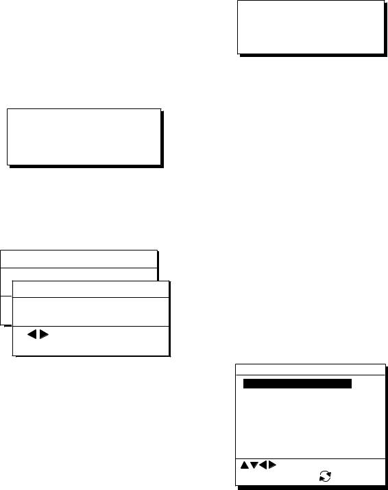
3)Press 1 to display the PLOTTER SETUP menu.
PLOTTER SETUP
|
|
Memory Apportion |
|
Trk = 1000 / 2000Pt |
|||||||||||||||||||
|
|
|
|
|
|
|
|
|
|
|
|
|
|
|
|
|
|
|
|
|
|||
|
Bearing Ref. |
|
True |
|
|
|
Mag |
||||||||||||||||
|
|
Mag Variation |
|
|
|
|
|
|
|
|
|
|
|
|
|
|
|
|
|
|
|||
|
|
Auto |
|
|
|
|
|
Man |
|||||||||||||||
|
|
|
|
|
|
|
|
|
|
|
|
|
|
|
|
|
|
|
|
|
|
|
|
|
|
|
|
|
|
|
|
|
|
|
|
|
|
|
|
|
|
|
|
|
|
||
|
|
|
|
|
|
|
(07° W) |
|
|
|
(00° E) |
||||||||||||
|
|
|
|
|
|
|
|
|
|
|
|
|
|
|
|
|
|
||||||
|
|
Calculation |
|
|
|
|
|
R.L |
|
|
|
|
|
|
|
|
G.C |
|
|||||
|
|
|
|
|
|
|
|
|
|
|
|
|
|
|
|
|
|
|
|
|
|
|
|
|
|
|
|
|
|
|
|
|
|
|
|
|
|
|
|
|
|
|
|
||||
|
|
|
|
|
|
|
|
|
|
|
|
|
|
|
|
|
|
|
|
||||
|
|
|
|
|
|
|
|
|
|
|
|
|
|
|
|
|
|
|
|||||
|
|
User defined #1 |
|
|
RNG |
|
|
|
|
|
|
||||||||||||
|
|
|
|
|
|
|
|
|
|
|
|
|
|
|
|
|
|
||||||
|
|
User defined |
#2 |
|
|
|
|
SOG |
|
|
|
|
|
|
|||||||||
|
|
|
|
|
|
|
|
|
|
|
|
|
|
|
|
|
|
||||||
|
|
User defined |
#3 |
|
|
|
|
BRG |
|
|
|
|
|
|
|||||||||
|
|
User defined |
|
|
|
|
|
|
|
|
|
|
|
|
|
||||||||
|
|
|
|
|
|
|
|
|
|
|
|
|
|
||||||||||
|
|
#4 |
|
|
COG |
|
|
|
|
|
|
||||||||||||
|
|
|
|
|
|
|
|
|
|
|
|
|
|
|
|
|
|
|
|
|
|
|
|
ENT: Enter |
MENU: Escape |
||||||||||||||||||||||
Figure 2-9 PLOTTER SETUP menu
4)Press  or
or  to select Memory Apportion.
5)Enter amount of track to store, in four digits. To store 1,500 track points, for example, press 1, 5, 0, 0.
6)Press the NU/CU ENT key,  or
or  . You are asked if it is all right to erase all data.
Setting erases all data!
Are you sure to change ?
ENT: Yes |
MENU: No |
Figure 2-10
7)Press the NU/CU ENT key.
8)Press the MENU ESC key.
2-5
2. TRACK
2.11Selecting Bearing Reference
Ship's course and bearing to waypoint may be displayed in true or magnetic bearing. Magnetic bearing is true bearing plus (or minus) earth's magnetic deviation.
Displaying true or magnetic bearing
The default setting displays true bearings.
1)Press the MENU ESC key.
2)Press 9 to display the SYSTEM SETTINGS menu.
3)Press 1 to display the PLOTTER SETUP menu.
4)Press  or
or  to select Bearing Ref.
5)Press  or
or  to select True or Mag.
6)Press the NU/CU ENT key,  or
or  .
.
7)Press the MENU ESC key.
Entering magnetic variation
The location of the magnetic north pole is different from the geographical north pole. This causes a difference between the true and magnetic north direction. This difference is called magnetic variation, and varies with respect to the observation point on the earth. Magnetic variation may be entered automatically or manually.
1)Press the MENU ESC key.
2)Press 9 to display the SYSTEM SETTINGS menu.
3)Press 1 to display the PLOTTER SETUP menu.
4)Press  or
or  to select Mag Variation.
5)Press  or
or  to select Auto or Man. For automatic, current variation appears in parentheses.
6)For manual entry, enter variation in two digits, referring to a nautical chart (00-99°). If the variation is 10°, for example, press 1,
0.
7)If necessary, press the 
 key to change coordinate from east to west or vice versa.
8)Press the NU/CU ENT key.
9)Press the MENU ESC key.
2-6
3. MARKS
3.1Entering/Erasing Marks
Marks can be inscribed on the Plotter 1 and Plotter 2 displays. You may inscribe a mark anywhere, in one of 13 shapes. Further, marks can be connected with lines.
Note 1: When the mark memory becomes full no marks can be entered. When this occurs, the buzzer sounds and the message shown below appears on the display for three seconds to alert you. To enter a mark when the mark memory is full, erase unnecessary marks.
Can’t save mark
Memory full
Figure 3-1
Entering marks
At own ship position
1)Press the CURSOR ON/OFF key to turn off the cursor.
2)Press the MARK key.
At cursor intersection
1)Press the CURSOR ON/OFF key to turn on the cursor.
2)Operate the cursor keys to place the cursor on the location for the mark. Select a mark shape you want. Refer to section 3.2.
3)Press the MARK key.
Erasing marks
CAUTION
All marks, including event marks and the MOB mark, are erased on the ERASE MARK menu. Be absolutely sure you want to erase all marks; erased marks cannot be restored.
Erasing individual marks
1)Place cursor on the mark to erase.
2)Press the CLEAR key.
Erasing all marks
1)Press MENU ESC and 3 to display the ERASE TRACK/MARK menu.
ERASE TRACK/MARK
Erase Track |
|
|
|
|
|
|
|
|
|
No |
|
|
Yes |
||
|
|
|
|
|
|
|
|
|
|
|
|
|
|
|
|
|
|
|
|
|
|
|
|
Erase Mark |
|||||||
|
No |
||||||
|
|
Yes |
|||||
Track Pts. Used: 345/1000 Pt
Mark Pts. Used: 123/1000 Pt


 : Select
MENU: Escape
Figure 3-2 ERASE TRACK/MARK menu
2)Press  or
or  to select Erase Mark.
3)Press  to select YES.
Are you sure to erase ?
ENT: Yes |
MENU: No |
Figure 3-3
4)Press the NU/CU ENT key.
5)Press the MENU ESC key.
3-1
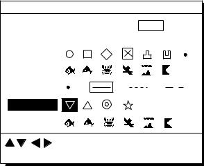
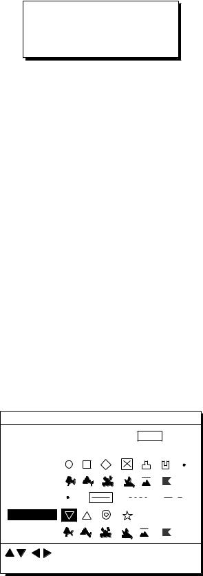
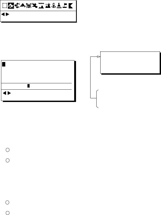
3.2Selecting Mark Shape
13 mark shapes are available. Select mark shape as follows:
1)Press MENU ESC and 2 to display the TRACK/MARK SETUP menu.
TRACK/MARK SETUP
Track Rec |
Time |
Dist |
|
(01’00) |
(00.50nm) |
Mark Shape |
|
|
Mark Line |
|
|
Event Mark |
|
|
|
: Select |
ENT: Enter |
MENU: Escape |
Figure 3-4 TRACK/MARK SETUP menu
2)Press  or
or  to select Mark Shape.
3)Press  to
to  select mark shape desired.
4)Press the NU/CU ENT key.
5)Press the MENU ESC key.
The next mark entered will be inscribed in the shape selected here.
3.3Connecting Marks
(selecting mark connection line)
Marks can be connected with lines. Three types of connection lines are available and the "•" setting disables connection of lines.
1)Press MENU ESC and 2.
2)Press  or
or  to select Mark Line.
3)Press  to
to  to select mark line desired other than "•".
4)Press the NU/CU ENT key.
5)Press the MENU ESC key.
3-2

3.4Entering Event Marks
Event marks can denote any important present position. Event marks can be saved as ordinary marks and the unit automatically numbers them from 01 to 99.
Note 1: When the mark memory becomes full no event marks can be entered. When this occurs, the buzzer sounds and the message shown below appears on the display for three seconds to alert you. To enter an event mark when the mark memory is full, erase unnecessary event marks.
Can’t save event
Memory full
Figure 3-5
Entering event marks
1)Press the EVENT MOB key less than three seconds. The position at the exact moment the key is pressed is saved as an event position.
Saved event position
34° 40.123’ N
135° 21.123’ E
Figure 3-6
To erase event marks, see "3.1
Entering/Erasing Marks".
3. MARKS
3.5Selecting Event Mark Shape
Event marks are available in 10 shapes. Select event mark shape as follows.
1)Press MENU ESC and 2 to display the TRACK/MARK SETUP menu.
2)Press  or
or  to select Event Mark.
3)Press  or
or  to select event mark shape desired.
4)Press the NU/CU ENT key.
5)Press the MENU ESC key.
The next event mark entered will be inscribed in the shape selected here.
3-3

3.6Entering the MOB Mark
The MOB mark denotes man overboard position. To mark man overboard position, press the EVENT MOB key more than three seconds. When the key is pressed, the position at the exact moment the key is pressed automatically becomes the destination. Further, the Plotter display replaces the display in use when it is other than a plotter display.
Only one MOB mark may be entered, and each time the MOB mark is entered the previous MOB mark and its position data are written over.
1)Press the EVENT MOB key for at least three seconds.
The MOB mark ("M") is entered at the MOB position and the message shown in Figure 3-7 appears.
Saved MOB position
Are you sure to change course to MOB position ?
ENT: Yes |
MENU: No |
Figure 3-7
2)Press the NU/CU ENT key. If the display in use is Highway, Navigation or Data, they are automatically replaced by the Plotter display.
Note: You may cancel MOB position as destination by pressing the MENU ESC key instead of the NU/CU ENT key at step 2. Note that the MOB mark remains on the display.
Erasing MOB mark
To erase a MOB mark, you must first cancel it as a GOTO waypoint and then erase all marks.
1)Press the GOTO key.
2)Press the 5 key to choose Cancel.
3)You are prompted to release GOTO; press the NU/CU ENT key.
4)Press the MENU ESC and 3 to display the ERASE TRACK/MARK menu.
5)Press  to choose Erase Mark.
6)Press  to choose Yes.
7)Press the NU/CU ENT key.
3-4
4. NAVIGATION PLANNING
4.1Registering Waypoints
In navigation terminology a waypoint is a particular location on a voyage whether it be a starting, intermediate or destination waypoint.
The GP-150 can store 999 waypoints, numbered from 001-999. Waypoints can be registered four ways:
•by cursor
•by MOB position or event position
•at own ship's position
•by range and bearing from position, and
•through the waypoint list.
Registering waypoints by the cursor
1)Press the WPT RTE key. The Waypoint/Route menu appears.
Waypoint/Route |
|
|
1. Cursor |
|
|
2. |
MOB/Event Position |
|
3. |
Own ship Position |
|
4. |
R/B to Position |
|
5. |
Waypoint List |
|
6. |
Route Planning |
|
|
: Cursor |
|
ENT: Enter |
MENU: Escape |
|
Figure 4-1 Waypoint/Route menu
2)Press 1 to select Cursor. The following display appears.
Place cursor on desired location
ENT: Enter |
MENU: Escape |
Figure 4-2
The display changes to Plotter 2 when the Highway, Navigation or Data mode is in use.
3)Press the cursor pad to place the cursor on the location desired for the waypoint.
4)Press the NU/CU ENT key.
A window similar to the one shown in Figure 4-3 appears. The waypoint's position and date and time registered appear on the first and second lines. Waypoints are automatically given the youngest empty waypoint number and this number appears on the third line. You may, however, assign a different number. If the waypoint shares the same position with a mark, the mark's position and date and time entered are registered as waypoint data.
If the waypoint memory is full, the waypoint number line in the window is blank. In this case waypoints cannot be entered unless a waypoint is written over or deleted.
To assign waypoint number, go to step 5. If you do not want to change the waypoint number, go to step 6 to select mark shape and enter comment.
30° 12.345’ N 135° 23.456’ W AUG 12’ 95 12 : 34U
No. : 123
Mark :
Cmnt :
|
: Cursor |
|
: Column |
|
|
|
MENU: Escape |
||
ENT: Enter |
||||
Figure 4-3
5)Enter waypoint number, in three digits (001-999).
4-1
4. NAVIGATION PLANNING
6)Press  to select waypoint mark shape. The following display appears.
: Cursor |
|
ENT: Enter |
MENU: Escape |
Figure 4-4 Screen for selecting waypoint mark shape
7)Press  or
or  to select mark shape.
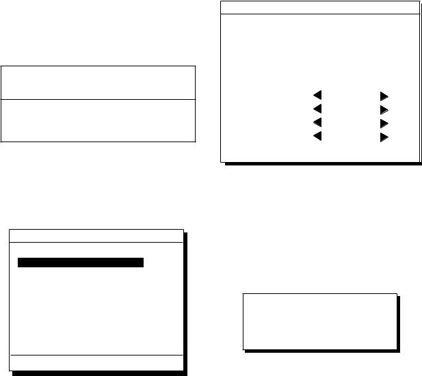
8)Press the NU/CU ENT key. The display shown in Figure 4-5 appears.
ABCDE FGHIJ KLMNO PQRST UVWXYZ
abcde fghij klmno pqrst uvwxyz
1 2 3 4 5 6 7 8 9 0 _ # % ’ ( ) + - . / : ; < = > ?
ENTER
COMMENT: _ _ _ _ _ _ _ _ _ _ _ _ |
: Cursor |
|
ENT: Set |
MENU: Escape |
Figure 4-5 Screen for entry of comment for waypoint
9)You may enter a comment, as shown in the procedure which follows, or skip to step 10 to finish. The comment may consist of up to 12 alphanumeric characters.
1Press the cursor keys to select alphanumeric character.
2Press the NU/CU ENT key. Selected character appears on the COMMENT line.
٠To create a space, select "_".
٠Numeric data can be input directly by pressing numeric keys.
٠To clear wrong data, press the
CLEAR key.
3Repeat steps 1 and 2 to complete the comment.
4Select ENTER and press the NU/CU ENT key.
10)Press the NU/CU ENT key. Control is returned to the last used display mode.
When the waypoint number entered at step 5 already exists, the message shown in Figure 4-4 appears if the waypoint is part of the current destination or route or is part of a route. If it is alright to write over the waypoint and its data, press the NU/CU ENT key. To change waypoint number, press the MENU ESC key.
 1st line
Are you sure to change ?
ENT: Yes MENU: No
This wpt is GOTO
This wpt is in registered route
This wpt is in selected route
Figure 4-6
Note: If you fail to enter waypoint number, "Enter waypoint number" appears on the display for three seconds.
4-2
Registering waypoints by MOB position/event position
The MOB position or an event position can be registered as a waypoint. Event marks are numbered from 01 to 99; 01 is the latest event mark.
Note: You cannot register a MOB position or event position when there are no MOB positions or event positions saved. The buzzer sounds and the message shown in Figure 4-7 appears for three seconds to alert you.
No MOB/event data in memory
Figure 4-7
1)Press the WPT/RTE key.
2)Press 2 to select MOB/Event Position. The display shown in Figure 4-8 appears.
[MOB] Displaying MOB data
34° 12.345’ N 130° 23.456’ E
AUG 12’ 94 19 : 25U [#01] Displaying event data
34° 12.:Recall345’ N 130° 23.456’ E
ENT:Enter AUGMENU:Escape12’ 95 19 : 25U
: Paging
ENT: Enter MENU: Escape
Figure 4-8
3)Press  or
or  to display the MOB position or event position to register as a waypoint.
4)Press the NU/CU ENT key.
5)Follow steps 5 through 11 in "Registering waypoints by the cursor" on page 4-1.
4. NAVIGATION PLANNING
Registering waypoints by own ship's position
Note: When there is no position data, you cannot register a waypoint at own ship's position. The buzzer sounds and the following message appears.
No position data
Figure 4-9
1)Press the WPT/RTE key.
2)Press 3 to select Own Ship Position.
3)Follow steps 5 through 11 in "Registering waypoints by the cursor" on page 4-1.
Registering waypoints using range and bearing from a position
This method is useful for entering a waypoint using range and bearing from a pre-registered waypoint.
Range and bearing to a position are calculated according to the sailing method (rhumb line or great circle) chosen on the PLOTTER SETUP menu. You may choose the unit of range on the UNIT SETUP menu.
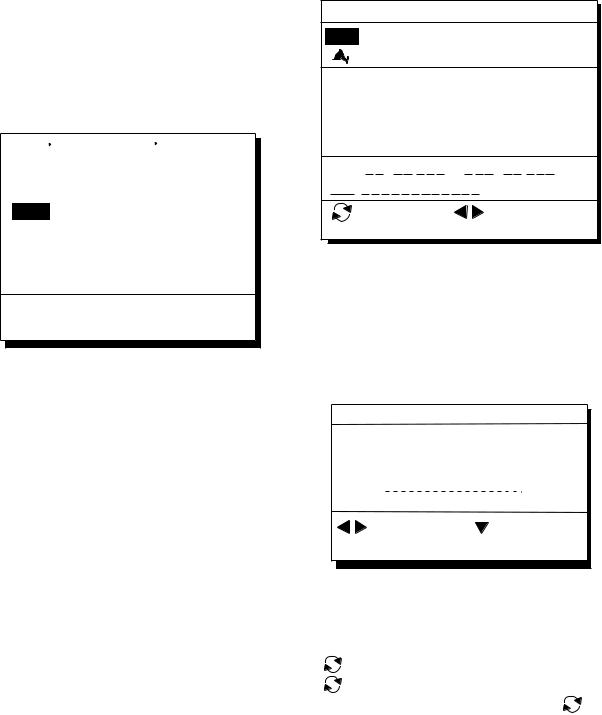
1)Press the WPT/RTE key.
2)Press the 4 key to display the R/B to Position display.
R/B to Position
From1. CursorWaypoint No. _ _ _
_ _ _ _. _ _ _’N _ _ _ _ _ _._ _ _’W
Range 0000.000nm
Bearing 000.00
: Cursor |
MENU: Escape |
ENT: Calculation |
: N/S, E/W |
R/B Position Display
3)Enter waypoint (000-999) from which to reference range and bearing. (000 is own ship position.)
4-3
4. NAVIGATION PLANNING
Note: Alternatively, you may enter position, leaving the waypoint number blank.
4)Enter range and bearing you wish to use to calculate position of new waypoint.
5)Press the NU/CU ENT key. The display now looks something like the one below.
_ _ _ _. _ _ _’N _ _ _ _ _ _._ _ _’W
3232.22’N 13341.853’WJUN 6’ 06 7:30U
No. : 002
Mark: _
Cmnt: _ _ _ _ _ _ _ _ _ _ _ _ _

 : Cursor
  : Column
ENT: Enter
6)If necessary, change waypoint number and add a comment. For how to enter a comment see page 4-2.
7)Press the CU/NU ENT key to finish.
Note: If waypoint number entered at step 6) is an existing number, a part of a registered route, a part of a currently selected route, or a GOTO waypoint, a prompt asks if it is OK to write over the waypoint. Follow the instructions in the prompt to write over the mark number or escape.
Registering waypoints through the waypoint list
1)Press the WPT/RTE key.
2)Press 5 to display the waypoint list.
3)Press  to select position format; latitude and longitude or LOP.
WAYPOINT LIST (L/L)
001 34° 12.345’ N 130° 23.456’ W MARINE POINT AUG 12’ 95 12 : 35U
002 36° 12.345’ N 135° 23.456’ W
|
|
|
A POINT |
|
|
|
|
|
|
|
|
|
|
|
|
|
|
|
|
|
AUG 13’ 95 |
|
13 : 45U |
||||||||||||||||||||||||||||||||||
|
|
|
|
|
|
|
|
|
|
|
|
|
|
|
|
|
|
|
|
|
|
|
|
|
|
|
|
|
|
|
|
|
|
|
|
|
|
|
|
|
|
|
|
|
|
|
|
|
|
|
|
|
|
|
|
|
|
|
003 |
|
° |
. |
|
|
|
|
|
’ N |
° . |
|
|
’ W |
|||||||||||||||||||||||||||||||||||||||||||
|
|
|
|
|
|
|
|
|
|
|
|
|
|
|
|
|
|
|
|
|
|
|
|
|
|
|
|
|
|
|
|
|
|
|
|
|
|
|
|
|
|
|
|
|
|
|
|
|
|
|
|
|
|
|
|
|
|
|
004 |
|
° . |
|
|
|
|
|
’ N |
° . |
|
|
’ W |
||||||||||||||||||||||||||||||||||||||||||||
|
|
|
|
|
|
|
|
|
|
|
|
|
|
|
|
|
|
|
|
|
|
|
|
|
|
|
|
|
|
|
|
|
|
|
|
|
|
|
|
|
|
|
|
|
|
|
|
|
|
|
|
|
|
|
|
|
|
|
|
|
: L/L’LOP |
|
|
|
|
|
|
|
|
|
|
|
|
|
|
MENU: |
: Edit |
|
|
|
|
|
|||||||||||||||||||||||||||||||||
|
|
|
|
|
|
|
|
|
|
|
|
|
|
|
|
|
|
|
|
|
|
|
|
|
|
|
|
|
|
|
|
|
|
|
|
|
|
|
|
|
|
|
|
|
|
|
|||||||||||
|
ENT: Enter |
|
|
|
|
|
|
|
|
|
|
|
|
|
|
|
Escape |
||||||||||||||||||||||||||||||||||||||||
Figure 4-10
4)Press  or
or  to select unused waypoint number.
5)Press  or
or  to enter position. The display should now look something like Figure 4-11.
Edit = Waypoint : 001
_ _°_ _._ _ _’ N _ _ _°_ _._ _ _’W
Mark : __ Cmnt :
|
: Cursor |
|
|
|
|
: Column |
|||||
|
|
|
|
|
|
ENT: Enter |
MENU: Escape |
||||
Figure 4-11
6)Enter latitude and longitude. To enter 34° 12.345' N 135° 23.456' E, for example, press;
([ |
]) |
3, 4, 1, 2, 3, 4. 5 |
|
([ |
]) |
1, 3, 5, 2, 3, 4, 5, 6 |
|
|
To change N to S or E to W, press |
. |
|
7)Press  .
.
8)Press  or
or  to select mark.
9)Press the NU/CU ENT key.
10)Enter comment.
11)Press the NU/CU ENT key twice.
The waypoint list reappears. Waypoint position and date and time the waypoint was entered appear on the list.
12)To enter another waypoint through the waypoint list, return to step 4.
13)Press the MENU ESC key to finish.
4-4
4.2 Editing Waypoints
1)Press WPT RTE and 5.
2)Press  or
or  to select waypoint to edit.
3)Press  .
.
4)Edit the contents of the waypoint.
5)Press the NU/CU ENT key. The message shown in Figure 4-12 appears if the waypoint is currently selected as destination, is part of a route, or is in the route currently selected as destination.
 1st line
Are you sure to erase ?
ENT: Yes MENU: No
This wpt is GOTO
This wpt is in registered route
This wpt is in selected route
Figure 4-12
6)Press the NU/CU ENT key.
The waypoint and its data are deleted. Enter new data, referring to "4.1 Registering Waypoints".
8) Press the MENU ESC key.
4.NAVIGATION PLANNING
4.3Deleting Waypoints
Deleting waypoints by the cursor
1)Place the cursor on the waypoint to delete.
2)Press the CLEAR key.
Deleting waypoints through the waypoint list
1)Press WPT RTE and 5.
2)Press  or
or  to select waypoint to delete.
3)Press the CLEAR key. The message shown in Figure 4-13 appears if the waypoint is currently selected as destination, is part of a route, or is in the route currently selected as destination.
 1st line
Are you sure to change ?
ENT: Yes MENU: No
This wpt is GOTO
This wpt is in registered route
This wpt is in selected route
Figure 4-13
Note: All waypoint marks (as well as all other marks) and their data can be cleared collectively by clearing the Plotter memory. For further details, see page 9-1.
4) Press the NU/CU ENT key.
Note: To cancel erasure, press the MENU ESC key instead of the NU/CU ENT key. The waypoint list appears.
5) Press the MENU ESC key.
4-5
4. NAVIGATION PLANNING
4.4Registering Routes
Often a trip from one place to another involves several course changes, requiring a series of route points which you navigate to, one after another. The sequence of waypoints leading to the ultimate destination is called a route. The GP-150 can automatically advance to the next waypoint on a route, so you do not have to change the destination waypoint repeatedly.
The GP-150 can store 30 routes and each route may contain up to 30 waypoints. Routes can be registered while in the Plotter 1 or Plotter 2 display mode.
Registering routes
1)Press the WPT/RTE key.
2)Press 6 to select Route Planning. The route list appears.
ROUTE LIST
|
No. PTS Total Dist. |
|
|
TTG |
|
|
|
Remarks |
||||||||||||||||||||||||
|
01 |
|
30 |
|
|
|
1234 . 56 nm 12D15H28M |
UseFwd |
||||||||||||||||||||||||
|
|
|
|
|
|
|
|
|
|
|
|
|
|
|
|
|
|
|
|
|
|
|
|
|
|
|
|
|
|
|
||
|
02 |
25 |
|
234 . 56 nm |
|
|
|
|
|
|
|
|
|
|
|
|
|
|
||||||||||||||
|
|
|
2D08H35M |
|||||||||||||||||||||||||||||
|
|
|
|
|
|
|
|
|
|
|
|
|
|
|
|
|
|
|
|
|
|
|
|
|
|
|
|
|
|
|
|
|
|
|
|
|
|
|
|
|
|
|
|
|
|
|
|
|
|
|
|
|
|
|
|
|
|
|
|
|
|
|
|||
|
|
|
*999. 99 nm |
|
|
|
|
|
|
|
|
|
|
|||||||||||||||||||
|
03 |
30 |
|
|
|
|
*9D*9H*9M |
|
|
|||||||||||||||||||||||
|
|
|
|
|
|
|
|
|
|
. |
|
|
|
nm |
|
|
|
|
|
|
|
|
|
|
|
|
|
|
||||
|
|
|
|
|
|
|
|
|
|
|
|
|
|
|
|
|
|
|
|
|
|
|
|
|
||||||||
|
|
|
|
|
|
|
|
|
|
|
|
|
|
|
|
D |
H |
M |
||||||||||||||
|
04 |
|
|
|
|
|
|
|
|
|
|
|
|
|
|
|||||||||||||||||
|
|
|
|
|
|
|
|
|
|
|
|
|
|
|
|
|
|
|
|
|
|
|
|
|
||||||||
|
|
|
|
|
|
|
|
|
|
|
||||||||||||||||||||||
|
05 |
30 |
6543 . 21 nm |
|
|
|
|
|
|
|
|
|
|
|
|
|
|
|||||||||||||||
|
|
|
34D23H45M |
|||||||||||||||||||||||||||||
|
|
|
|
|
|
|
|
|
|
. |
|
|
|
nm |
|
|
|
|
|
|
|
|
|
|
|
|
|
|
||||
|
|
|
|
|
|
|
|
|
|
|
|
|
|
|
|
D |
H |
M |
||||||||||||||
|
06 |
|
|
|
|
|
|
|
|
|
|
|
|
|
|
|||||||||||||||||
|
|
|
|
|
|
|
|
|
|
|
|
|
|
|
|
|
|
|
|
|
|
|
|
|
|
|
|
|
|
|
|
|
|
|
|
|
|
|
|
|
|
|
|
|
|
|
|
|
|
|
|
|
|
|
|
||||||||||
|
|
|
|
|
: Route No. |
MENU: |
: Edit |
|
|
|
|
|
||||||||||||||||||||
|
|
|
|
|
|
|
|
|
|
|
|
|
|
|
|
Escape |
||||||||||||||||
|
ENT: Enter |
|||||||||||||||||||||||||||||||
Remarks Use: In use
Fwd: Traverse waypoints in forward order Rvs: Traverse waypoints in reverse order
Figure 4-14 Route list
3)Press  or
or  to select route number.
4)Press  .
.
The route planning/waypoint list window appear as shown in Figure 4-15. The waypoint list window lists the position and data for each registered waypoint. No position or data appears for empty waypoints.
|
ROUTE : 01 (In Use , REVERSE) |
|
|
|
||||||||||
|
|
|
|
|||||||||||
|
|
|
skip Distance |
TTG |
|
|
|
|
||||||
|
Trial Speed : Auto |
Man |
(012.0kt) |
|
|
Route |
||||||||
|
|
01 |
|
|
EN |
|
|
. |
|
nm |
D |
M |
H |
|
|
|
|
|
|
|
editing |
||||||||
|
|
02 |
|
EN |
|
|
. |
|
nm |
D |
M |
H |
||
|
|
|
|
|
screen |
|||||||||
|
|
|
|
|
|
|
|
|
|
|
|
|
|
|
|
|
|
34° 12.345’ N 130° 23.456’ E |
|
|
|
||||||||
|
001 |
|
|
|
||||||||||
|
|
|
MARINE POINT |
AUG 12’ 95 |
12 : 35U |
|
||||||||
|
002 |
36° 12.345’ N 135° 23.456’ E |
|
|
Waypoint |
|||||||||
|
|
|
A POINT |
|
AUG 13’ 95 |
13 : 45U |
list |
|||||||
|
|
|
|
|
||||||||||
|
|
|
: RTE |
|
WPT |
CLEAR: Delete |
|
|
||||||
|
|
ENT: Enter |
|
MENU: |
Escape |
|
|
|
|
|||||
Use: In use
Fwd: Traverse waypoints in forward order
Rvs: Traverse waypoints in reverse order
Figure 4-15 Route editing screen
5)If required, press  to enter the speed by which to calculate time-to-go.
6)Press  or
or  to select Auto or Man. Auto: Current average speed is used to calculate the time-to-go.
Manual: Entered speed is used to calculate the time-to-go. Enter speed and press  .
.
Route waypoints may be registered two ways: entering waypoint number directly or through the route editing screen. Follow 1 or 2 below.
1 Entering waypoint number directly
7)Enter waypoint number, in three digits. The cursor shifts to the "Skip" window. The procedure for skipping a waypoint is shown on page 5-5. For now, go to the next step.
8)Press  to continue. If the waypoint entered in step 7 does not exist, you are informed that the waypoint does not exist and entry is cancelled.
9)Enter other route waypoints by repeating steps 7 and 8.
10)Press MENU ESC to finish.
4-6
Loading...