


 Loading...
VC70N0 Vehicle Computer
Product Reference Guide
VC70N0 Vehicle Computer
Product Reference Guide
72-164686-05 RevisionA December 2020

ii VC70N Vehicle Computer Product Reference Guide
No part of this publication may be reproduced or used in any form, or by any electrical or mechanical means, without permission in writing. This includes electronic or mechanical means, such as photocopying, recording, or information storage and retrieval systems. The material in this manual is subject to change without notice.
The software is provided strictly on an “as is” basis. All software, including firmware, furnished to the user is on a licensed basis. We grant to the user a non-transferable and non-exclusive license to use each software or firmware program delivered hereunder (licensed program). Except as noted below, such license may not be assigned, sublicensed, or otherwise transferred by the user without prior written consent. No right to copy a licensed program in whole or in part is granted, except as permitted under copyright law. The user shall not modify, merge, or incorporate any form or portion of a licensed program with other program material, create a derivative work from a licensed program, or use a licensed program in a network without written permission.
The user agrees to maintain copyright notice on the licensed programs delivered hereunder, and to include the same on any authorized copies it makes, in whole or in part. The user agrees not to decompile, disassemble, decode, or reverse engineer any licensed program delivered to the user or any portion thereof.
We reserve the right to make changes to any software or product to improve reliability, function, or design. We do not assume any product liability arising out of, or in connection with, the application or use of any product, circuit, or application described herein.
No license is granted, either expressly or by implication, estoppel, or otherwise under any of our intellectual property rights. An implied license only exists for equipment, circuits, and subsystems contained in our products.
Warranty
Subject to the terms of Zebra hardware warranty statement, the VC70 Vehicle Computer products are
warranted against defects in workmanship and materials for a period of one year from the date of shipment. For the complete Zebra hardware product warranty statement, go to: www.zebra.com/warranty
Revision History
Changes to the original manual are listed below:
Change |
Date |
Description |
-05 Rev A |
12/2020 |
Replaced master/slave references with central/peripheral (for Bluetooth) and |
|
|
controller/follower (for non-Bluetooth) |
-04 Rev A |
1/2019 |
Correct DC power cable part number. |
-03 Rev A |
7/2018 |
Update memory size. |
-02 Rev C |
8/2016 |
Correct COM port on page 5-15, step 15. (Change from COM 9 to COM1). |
-02 Rev B |
1/2016 |
Add Caution not to use tool when connecting cables to COM and USB ports. |
-02 Rev A |
2/7/2015 |
Zebra Re-branding. Update accessory table. |
-01 Rev C |
09/01/2014 |
Revision C |
-01 Rev B |
09/19/13 |
Revision B Release |
-01 Rev A |
11/30/12 |
Initial release. |

iii

iv VC70N Vehicle Computer Product Reference Guide

Table of Contents
Warranty ............................................................................................................................................... |
ii |
Revision History.................................................................................................................................... |
ii |
About This Guide |
|
Introduction........................................................................................................................................... |
xi |
Documentation Set ......................................................................................................................... |
xi |
Configurations....................................................................................................................................... |
xii |
Software Versions........................................................................................................................... |
xii |
Chapter Descriptions ............................................................................................................................ |
xiii |
Notational Conventions......................................................................................................................... |
xiv |
Related Documents and Software........................................................................................................ |
xiv |
Service Information............................................................................................................................... |
xiv |
Returning the Vehicle Computer for Service................................................................................... |
xv |
Chapter 1: Getting Started |
|
Introduction .......................................................................................................................................... |
1-1 |
Unpacking the VC70 ............................................................................................................................ |
1-1 |
Features ............................................................................................................................................... |
1-1 |
Accessories ......................................................................................................................................... |
1-4 |
Chapter 2: Installation |
|
Introduction .......................................................................................................................................... |
2-1 |
Electrical Power Wiring ........................................................................................................................ |
2-2 |
Forklifts and Trucks with 12V, 24V, 36V and 48V Batteries .................................................... |
2-3 |
Ignition Sensing ............................................................................................................................. |
2-5 |
VC70 Power States ............................................................................................................................. |
2-6 |
Installing the VC70 on a Cart, a Wall, or a Desktop ............................................................................ |
2-7 |
Mounting the Bracket on a Desktop ............................................................................................... |
2-7 |
Connecting the Vehicle Computer to AC Power ............................................................................ |
2-8 |
Installing the DC Power Supply (PSU) on the VC70 ........................................................................... |
2-9 |
Installing a Micro SD Card ................................................................................................................... |
2-10 |
RAM Mount Installation ........................................................................................................................ |
2-11 |

vi VC5090 Vehicle Computer Product Reference Guide
U-Mount Installation ............................................................................................................................. |
2-13 |
Installing the VC70 on a Forklift ........................................................................................................... |
2-14 |
Positioning the Vehicle Computer .................................................................................................. |
2-14 |
U-Mount Installation Template ................................................................................................. |
2-16 |
Mounting onto an Over-Head Cross-Beam Example ............................................................... |
2-17 |
Mounting onto an Over-Head Cage Example .......................................................................... |
2-17 |
Mounting on a Dashboard or Horizontal Surface Example ...................................................... |
2-19 |
Installing the Optional QWERTY/AZERTY Keyboard .......................................................................... |
2-20 |
Installing the Optional VC5090 Keyboard on the VC70 ....................................................................... |
2-22 |
Installing a Numeric Keyboard ............................................................................................................. |
2-23 |
Keyboard Protection Grill Installation ................................................................................................... |
2-25 |
Installing the Scanner Mount ............................................................................................................... |
2-26 |
Installing a Stubby Antenna ................................................................................................................. |
2-27 |
Installing the External Roof-mounted Antenna .................................................................................... |
2-28 |
Connecting Accessories ...................................................................................................................... |
2-29 |
Connecting an External Speaker to the Vehicle Computer ................................................................. |
2-29 |
Installing an External Microphone Mount ............................................................................................. |
2-29 |
Chapter 3: Operating the VC70 |
|
Introduction .......................................................................................................................................... |
3-1 |
Control Panel Applications ................................................................................................................... |
3-1 |
Quick Access Panel ............................................................................................................................. |
3-4 |
Power Button ................................................................................................................................. |
3-4 |
Charging LED ................................................................................................................................ |
3-4 |
COMM LED .................................................................................................................................... |
3-5 |
Brightness and Speaker Buttons ................................................................................................... |
3-6 |
Function LED ................................................................................................................................. |
3-6 |
Programmable (“P”) Keys .............................................................................................................. |
3-6 |
Using the Keyboard ............................................................................................................................. |
3-6 |
Soft Input Panel (SIP) Keyboards .................................................................................................. |
3-6 |
Keyboard Functionality .................................................................................................................. |
3-10 |
Adjusting the Brightness ...................................................................................................................... |
3-12 |
Controlling Screen Brightness ....................................................................................................... |
3-12 |
Controlling the External Keyboards Backlight ................................................................................ |
3-13 |
Adjusting the Volume ........................................................................................................................... |
3-13 |
Taskbar ................................................................................................................................................ |
3-14 |
Start Button .................................................................................................................................... |
3-15 |
Programs Menu ............................................................................................................................. |
3-15 |
Desktop Button .............................................................................................................................. |
3-16 |
Task Manager and Properties ........................................................................................................ |
3-16 |
Task Manager .......................................................................................................................... |
3-16 |
Properties ................................................................................................................................. |
3-17 |
Using Voice Communication ................................................................................................................ |
3-18 |
Resetting the Vehicle Computer .......................................................................................................... |
3-19 |
Performing a Warm Boot ............................................................................................................... |
3-19 |
Performing a Cold Boot .................................................................................................................. |
3-19 |
Boot Persistence ............................................................................................................................ |
3-20 |
Power Status ....................................................................................................................................... |
3-22 |
Power On ....................................................................................................................................... |
3-22 |
Table of Contents |
vii |
|
|
Low Power Mode ........................................................................................................................... |
3-22 |
Methods of Suspension ........................................................................................................... |
3-22 |
Critical Suspension ........................................................................................................................ |
3-22 |
Waking the Vehicle Computer ....................................................................................................... |
3-23 |
Reduced Power Consumption ....................................................................................................... |
3-23 |
Controlling the Display ......................................................................................................................... |
3-25 |
Using the Display ........................................................................................................................... |
3-25 |
Using the Keyboard ....................................................................................................................... |
3-26 |
Screen Lock ................................................................................................................................... |
3-28 |
Checking Backup Battery Status ......................................................................................................... |
3-29 |
Disconnecting the Backup Battery ................................................................................................. |
3-29 |
Checking the Status of the Backup Battery ................................................................................... |
3-29 |
Sensors Configuration ......................................................................................................................... |
3-30 |
Desiccant Warning ......................................................................................................................... |
3-30 |
TouchPanel Heater ........................................................................................................................ |
3-32 |
Real Time Log ..................................................................................................................................... |
3-32 |
Shock Events Log ................................................................................................................................ |
3-33 |
Chapter 4: DataWedge Scanner Connection |
|
Introduction .......................................................................................................................................... |
4-1 |
Scanner Connection Method ............................................................................................................... |
4-2 |
Scanner/SSI Firmware Compatibility ................................................................................................... |
4-2 |
Scanner/SSI Firmware Compatibility ................................................................................................... |
4-3 |
Installing a Scanner ............................................................................................................................. |
4-3 |
Connect LS3408-ER Corded Scanner to a Serial Port of the VC70 (SSI) ............................... |
4-4 |
Connect DS3508-ER Corded Scanner to a Serial Port of the VC70 (SSI) .............................. |
4-8 |
Connect LS3408-ER Corded Scanner to a Serial Port of the VC70 (Serial) ........................... |
4-11 |
Connect DS3508-ER Corded Scanner to a Serial Port of the VC70 (Serial) ........................... |
4-14 |
Connect a Bluetooth Scanner DS3578 Directly to the VC70 (SPP Profile) ............................. |
4-19 |
Connect a Bluetooth Scanner LS3578 Directly to the VC70 (SPP Profile) .............................. |
4-25 |
Connect a Bluetooth Scanner RS507 Directly to the VC70 (Scan Profile) .............................. |
4-29 |
Connect a Bluetooth Scanner RS507 Directly to the VC70 (SPP Profile) ............................... |
4-31 |
Chapter 5: TelnetCE Configuration |
|
Introduction .......................................................................................................................................... |
5-1 |
Scanner Connection Method ............................................................................................................... |
5-2 |
Scanner/SSI Firmware Compatibility ................................................................................................... |
5-3 |
Wavelink TelnetCE .............................................................................................................................. |
5-3 |
Connect LS3408-ER Corded Scanner to a Serial Port of the VC70 (SSI) ............................... |
5-4 |
To connect a scanner: ) ........................................................................................................... |
5-4 |
Connect DS3508-ER Corded Scanner to a Serial Port of the VC70 (SSI) .............................. |
5-8 |
Connect LS3408-ER Corded Scanner to a Serial Port of the VC70 (Serial) ........................... |
5-11 |
Connect DS3508-ER Corded Scanner to a Serial Port of the VC70 (Serial) ........................... |
5-20 |
Connect LS3408-ER Scanner to USB Port of the VC70 (HID) ................................................ |
5-28 |
Connect LS3408-ER Corded Scanner to USB Port of the VC70 (Scan Handlers) .................. |
5-29 |
Connect DS3508-ER Scanner to USB Port of the VC70 (HID) ............................................... |
5-36 |
Connect DS3508-ER Serial Scanner to USB Port of the VC70 (Scan Handlers) .................... |
5-38 |
Connect a Bluetooth Scanner RS507 Directly to the VC70 (Scan Profile) .............................. |
5-44 |

viii VC5090 Vehicle Computer Product Reference Guide
Connect a Bluetooth Scanner RS507 Directly to the VC70 (SPP Profile) ............................... |
5-46 |
Connect a Bluetooth Scanner DS3578 Directly to the VC70 (SPP Profile) ............................. |
5-54 |
Connect a Bluetooth Scanner LS3578 Directly to the VC70 (SPP Profile) .............................. |
5-63 |
Chapter 6: Wireless LAN Applications |
|
Introduction .......................................................................................................................................... |
6-1 |
Signal Strength Icon ............................................................................................................................ |
6-2 |
Turning the WLAN Radio On and Off .................................................................................................. |
6-3 |
With Fusion .................................................................................................................................... |
6-3 |
Find WLANs Application ...................................................................................................................... |
6-3 |
Chapter 7: Using Bluetooth |
|
Introduction .......................................................................................................................................... |
7-1 |
Adaptive Frequency Hopping .............................................................................................................. |
7-1 |
Security ................................................................................................................................................ |
7-2 |
Turning the Bluetooth Radio Mode On and Off ................................................................................... |
7-2 |
Disabling Bluetooth ........................................................................................................................ |
7-2 |
Enabling Bluetooth ......................................................................................................................... |
7-3 |
Bluetooth Power States ................................................................................................................. |
7-4 |
Cold Boot ................................................................................................................................. |
7-4 |
Warm Boot ............................................................................................................................... |
7-4 |
Low Power ............................................................................................................................... |
7-4 |
Pairing Cordless Scanners .................................................................................................................. |
7-4 |
Discovering Bluetooth Device(s) .......................................................................................................... |
7-4 |
File Transfer Services .................................................................................................................... |
7-7 |
Create New File or Folder ........................................................................................................ |
7-8 |
Delete File ................................................................................................................................ |
7-8 |
Get File .................................................................................................................................... |
7-9 |
Put File ..................................................................................................................................... |
7-9 |
Connect to Internet Using Access Point ........................................................................................ |
7-9 |
OBEX Object Push Services .......................................................................................................... |
7-9 |
Send a Picture ......................................................................................................................... |
7-10 |
Headset Services ........................................................................................................................... |
7-11 |
Serial Port Services ....................................................................................................................... |
7-11 |
Personal Area Network Services ................................................................................................... |
7-12 |
Bluetooth Settings ................................................................................................................................ |
7-12 |
Device Info Tab .............................................................................................................................. |
7-12 |
Services Tab .................................................................................................................................. |
7-13 |
File Transfer Service ................................................................................................................ |
7-14 |
Personal Area Networking Service .......................................................................................... |
7-14 |
Serial Port Service ................................................................................................................... |
7-15 |
Headset Service ....................................................................................................................... |
7-16 |
Security Tab ................................................................................................................................... |
7-16 |
Discovery Tab ................................................................................................................................ |
7-16 |
Virtual COM Port Tab ..................................................................................................................... |
7-17 |
Miscellaneous Tab ......................................................................................................................... |
7-18 |
Table of Contents |
ix |
|
|
Chapter 8: Sync with Host Computer |
|
Introduction .......................................................................................................................................... |
8-1 |
Installing the Synchronization Software ............................................................................................... |
8-2 |
Vehicle Computer Setup ...................................................................................................................... |
8-2 |
Setting Up an ActiveSync Connection on the Host Computer (Windows XP) ..................................... |
8-3 |
Setting up a Partnership ................................................................................................................ |
8-4 |
Setting Up an Windows Mobile Device Center Connection on the Host Computer (Windows 7) ........ |
8-6 |
Setting up a Partnership ................................................................................................................ |
8-7 |
Chapter 9: Application Development and Deployment |
|
Introduction .......................................................................................................................................... |
9-1 |
Software Installation on Development PC (Application Development) ................................................ |
9-1 |
Platform SDK ................................................................................................................................. |
9-1 |
Zebra Developer Kit ....................................................................................................................... |
9-2 |
Installing Other Development Software ......................................................................................... |
9-2 |
Software Installation on Vehicle Computer .......................................................................................... |
9-2 |
ActiveSync ..................................................................................................................................... |
9-2 |
Micro SD Card ............................................................................................................................... |
9-4 |
Flash Storage ...................................................................................................................................... |
9-4 |
FFS Partitions ................................................................................................................................ |
9-4 |
Working with FFS Partitions ........................................................................................................... |
9-5 |
RegMerge.dll ............................................................................................................................ |
9-5 |
CopyFiles ................................................................................................................................. |
9-5 |
Non-FFS Partitions ........................................................................................................................ |
9-6 |
Chapter 10: Staging and Provisioning |
|
Introduction .......................................................................................................................................... |
10-1 |
MSP 3 Agent .................................................................................................................................. |
10-1 |
AppCenter ...................................................................................................................................... |
10-2 |
Chapter 11: Software Configuration |
|
Introduction .......................................................................................................................................... |
11-1 |
VC70 Operating System - Image Upgrade .......................................................................................... |
11-1 |
Updating the Image ........................................................................................................................ |
11-1 |
Monitor Mode ........................................................................................................................... |
11-1 |
To Update the Image ............................................................................................................... |
11-1 |
OSupgrade Mode ........................................................................................................................... |
11-2 |
Switch Between Microsoft and StoneStreet One (SS1) Bluetooth Stack ............................................ |
11-3 |
Often Used Registry Settings .............................................................................................................. |
11-3 |
Power Suspend .............................................................................................................................. |
11-3 |
COM1 Power Output to Scanner ................................................................................................... |
11-4 |
COM2 Power Output to Scanner ................................................................................................... |
11-4 |
External Antenna ........................................................................................................................... |
11-4 |
Ignition Timeout ............................................................................................................................. |
11-5 |
Registry Values for P1/P2/P3/P4 Keys .......................................................................................... |
11-5 |
Disabling the Fusion RX Sensitivity Degradation ........................................................................... |
11-6 |
VC70N0 WinCE 7.0 Registry Settings for Control Panel Applets .................................................. |
11-6 |

x VC5090 Vehicle Computer Product Reference Guide
Screen locking feature ............................................................................................................. |
11-6 |
Speaker control ........................................................................................................................ |
11-8 |
Setting COM5 as Default Serial Port ............................................................................................. |
11-9 |
Disable SIP from Auto-Launching ........................................................................................................ |
11-9 |
Force Warm Boot or Cold Boot After Resuming From Critical Suspension ......................................... |
11-9 |
Chapter 12: Maintenance |
|
Introduction .......................................................................................................................................... |
12-1 |
Maintaining the Vehicle Computer ....................................................................................................... |
12-1 |
Returning the Vehicle Computer for Service .................................................................................. |
12-2 |
Replacing the Desiccant Bag ......................................................................................................... |
12-2 |
Replacing the Backup Battery ........................................................................................................ |
12-3 |
Troubleshooting ................................................................................................................................... |
12-4 |
Appendix A: Specifications |
|
Technical Specifications ...................................................................................................................... |
A-1 |
Vehicle Computer .......................................................................................................................... |
A-1 |
Vehicle Computer Connectors ............................................................................................................. |
A-3 |
Glossary

About This Guide
Introduction
The VC70 Product Reference Guide provides information about the VC70 vehicle computer using Microsoft® Windows® CE 7.0 operating system and its accessories.
NOTE Screens and windows pictured in this guide are samples and can differ from actual screens.
Documentation Set
The documentation set for the VC70 is divided into guides that provide information for specific user needs.
•VC70 Quick Reference Guide - describes how to install and use the VC70 vehicle computer.
•VC70 Product Reference Guide - provides an in-depth description on how to use and setup the VC70 vehicle computer and its accessories.
•Microsoft Application Guide - describes how to use Microsoft developed applications that reside on the VC70 vehicle computer.
•Zebra Application Guide - describes how to use Zebra developed applications available for the VC70 vehicle computer.
•EMDK Help File - provides API information for writing applications.

xii VC70 Vehicle Computer Product Reference Guide
Configurations
This guide covers the following configurations: |
|
|
|||
Configuration |
Radios |
Display |
Memory |
Data |
|
Capture |
|||||
|
|
|
|
||
VC70 Full Screen |
WLAN: |
10.4” XGA |
1 GB DDR2 |
Optional |
|
|
802.11a/b/g/n |
1024 x 768 |
volatile memory, |
Scanner |
|
|
WPAN: Bluetooth |
Switchable to |
2 GB EMMC non |
|
|
|
|
SVGA |
volatile memory |
|
|
|
|
800x600 |
|
|
|
|
|
(4:3 format) |
|
|
|
OS |
Keypad |
Windows |
Optional USB |
CE 7.0 |
QWERTY or |
Professional |
AZERTY |
|
keyboard |
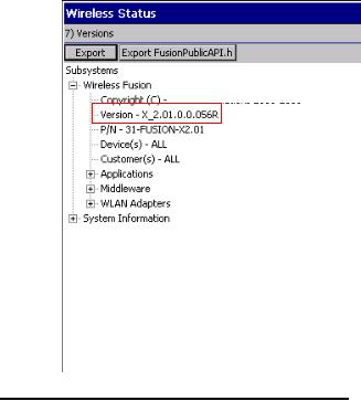
Software Versions
This guide covers various software configurations and references are made to operating system or software versions for:
•OEM version
•Fusion version.
OEM Software
To determine the OEM software version:
Tap Start > Settings > Control Panel > System Information icon > System tab.
Fusion Software
To determine the Fusion software version:
Tap Fusion icon > Wireless Status > Versions.
About This Guide |
xiii |
|
|
 © 2014 Symbol Technologies, Inc.
Chapter Descriptions
Topics covered in this guide are as follows:
•Chapter 1, Getting Started, provides information on getting the vehicle computer up and running for the first time.
•Chapter 2, Installation, provides instructions for installing the vehicle computer in a forklift, on a wall or on a desktop. Provides instructions for installing accessories.
•Chapter 3, Operating the VC70, explains how to use the vehicle computer. This includes instructions for powering on and resetting the vehicle computer, entering and capturing data.
•Chapter 4, DataWedge Scanner Connection, describes how to install the scanners and accessories for the VC70 vehicle computer.
•Chapter 5, TelnetCE Configuration, provides instructions required for connecting serial scanners in a Wavelink TelnetCE session via the VC70 vehicle computer
•Chapter 6, Wireless LAN Applications, provides instructions for using and configuring the mobile computer on a wireless network.
•Chapter 7, Using Bluetooth, explains how to use Bluetooth functionality on the vehicle computer.
•Chapter 8, Sync with Host Computer, provides instructions for installing and configuring ActiveSync.
•Chapter 9, Application Development and Deployment, provides instructions for installing the EMDK for C on the host computer and downloading software files to the vehicle computer.
•Chapter 10, Staging and Provisioning, provides instructions for staging and provisioning the vehicle computer.
•Chapter 11, Software Configuration, includes special configuration instruction for third party software used with the vehicle computer.

xivVC70 Vehicle Computer Product Reference Guide
•Chapter 12, Maintenance, includes instructions on cleaning and storing the vehicle computer, and provides troubleshooting solutions for potential problems during vehicle computer operation.
•Appendix A, Specifications, includes a table listing the technical specifications for the vehicle computer.
Notational Conventions
The following conventions are used in this document:
•“Vehicle computer” refers to the VC70 series of vehicle computers.
•Italics are used to highlight the following:
•Chapters and sections in this and related documents.
•Bold text is used to highlight the following:
•Key names on a keyboard
•Button names on a screen
•Dialog box, window and screen names
•Drop-down list and text box names
•Check box and radio button names
•Icons on a screen.
•Bullets (•) indicate:
•Action items
•Lists of alternatives
•Lists of required steps that are not necessarily sequential.
•Sequential lists (e.g., those that describe step-by-step procedures) appear as numbered lists.
Related Documents and Software
The following documents provide more information about the VC70 vehicle computers.
• VC70 Quick Reference Guide, p/n 72-76346-xx
For the latest version of this guide and all guides, go to: http://www.zebra.com/support.
Service Information
If you have a problem with your equipment, contact Zebra support for your region. Contact information is available at: http://www.zebra.com/support.
When contacting support, please have the following information available:
•Serial number of the unit
•Model number or product name
•Software type and version number.
Zebra responds to calls by email, telephone or fax within the time limits set forth in support agreements.

About This Guide |
xv |
|
|
If your problem cannot be solved by Zebra support, you may need to return your equipment for servicing and will be given specific directions. Zebra is not responsible for any damages incurred during shipment if the approved shipping container is not used. Shipping the units improperly can possibly void the warranty.
If you purchased your Zebra business product from a Zebra business partner, contact that business partner for support.
Returning the Vehicle Computer for Service
NOTE In the event, the vehicle computer needs to be shipped to Zebra for repair or maintenance, it is essential that the user perform the following steps to electrically disconnect the internal backup battery:
1.Disconnect the power cable from the VC70. The VC70 will continue to work on backup battery power.
2.Perform cold boot (Performing a Cold Boot on page 3-19). The backup battery will stop powering the VC70.

xvi VC70 Vehicle Computer Product Reference Guide

Chapter 1 Getting Started
Introduction
The VC70 is Zebra ultra-rugged forklift mounted computer. It is designed to maximize productivity in harsh environments. Its rugged construction and high-performance wireless networking enables real-time data access and collection in a wide range of environments — from the loading dock and freezer to the warehouse.
The VC70’s compact design improves visibility and reduces safety concerns while retaining large screen size (10.4”). Its 802.11 a/b/g/n WLAN provides real-time information that improves decision making, reduces errors, and enhances productivity. Its rugged design with integrated shock-mount and MIL-STD 810 military rating for shock and vibration ensures dependable operation in challenging environments. Its IP66 sealing, display, defroster and wide temperature range ensures operation in and out of -30oC freezer storage warehouse.
With its high-resolution and high-brightness display, the VC70 provides the user access to more information in low ambient light warehouse and outdoors.
The VC70 accessories allow backward compatibility with the VC5090 for easy and gradual migration.
Unpacking the VC70
When you remove the vehicle computer from its box, save the box and shipping material in case you need to ship or store the vehicle computer. Check the contents of the box against the invoice for completeness and contact your local Zebra service representative if there is a problem.
The VC70 shipping box contains:
•vehicle computer
•VC70 Quick Reference Guide
Features
The VC70 has the following features:
• Integrated 802.11a/b/g/n wireless LAN radio

1 - 2 VC70 Vehicle Computer Product Reference Guide
•Windows® CE 7.0 Professional Operating System
•TI OMAP4430 processor at 1GHz in turbo mode CPU
•1 GB DDR2 volatile memory, 2 GB EMMC non volatile memory
•10.4” XGA 1024 x 768, Switchable to SVGA 800x600, (4:3 format) color display
•Wireless and wired printing
•Integrated antennas
•Integrated speaker.
Antenna Port for |
Ambient Light Sensor |
|
|
Optional External |
|
Antenna |
|
|
+, P1 Key |
Display |
-, P2 Key |
|
Keyboard, P3 Key |
|
Speaker, P4 Key |
|
Brightness Key |
|
Function LED |
|
Power Button |
|
Charging LED |
|
COMM LED |
|
Internal Speaker |
Figure 1-1 VC70 Front View

Getting Started 1 - 3
Backup Battery Door
Antenna Port for |
|
|
|
|
|
|
|
|
|
Main |
|
|
|
|
|
Service Door |
|
|
|
|
|
|
|
|
|
|
|
|
|
|
|
|
|
|
|
||||||||||||||||||||||||||||||||||||||||||||||||||||||||||||||||||||||
|
|
|
|
|
|
|
|
|
|
|
|
|
|
|
|
|
|
|
|
|
|
|
|
|
|
|
|
|
|
|
|
|
|
|
|
|
|
|
|
|
|
|
|
|
|
|
|
|
|
|
|
|
|
|
|
|
|
|
|
|
|
|
|
|
|
||||||||||||||||||||||||||||||||||||||||
Optional External |
|
|
|
|
|
|
|
|
|
|
|
|
|
Switch |
|
|
|
|
|
|
|
|
|
|
|
|
|
|
|
|
|
|
|
|
|
|
|
|
|
|
|
|
|
|
|
|
|
|
|
|
|
|
|
|
|
|
|
|
|
|
|
|
|
|
|
|
|
|
|
|
|
||||||||||||||||||||||||||||||||||
Antenna |
|
|
|
|
|
|
|
|
|
|
|
|
|
|
|
|
|
|
|
|
|
|
|
|
|
|
|
|
|
|
|
|
|
|
|
|
|
|
|
|
|
|
|
|
|
|
|
|
|
|
|
|
|
|
|
|
|
|
|
|
|
|
|
|
|
|
|
|
|
|
|
|
|
|
|
|
|
|
|||||||||||||||||||||||||||
Figure 1-2 VC70 Back View |
|
|
|
|
|
|
|
|
|
|
|
|
|
|
|
|
|
|
|
|
|
|
|
|
|
|
|
|
|
|
|
|
|
|
|
|
|
|
|
|
|
|
|
|
|
|
|
|
|
|
|
|
|
|
|
|
|
|
|
|
|
|
|
|
|
|
|
|
|
|
|
|
|
|
|
|
|
|
|||||||||||||||||||||||||||
COM2 + CAN-bus COM1 Port |
|
|
Microphone External Speaker |
|
|
USB 1 |
|
|
|
|
|
|
|
|
|
|
|
|
|
|
|
USB 2 |
|||||||||||||||||||||||||||||||||||||||||||||||||||||||||||||||||||||||||||||||||||
Power |
|
|
|
|
|
|
|
|
|
|
|
|
|
|
|
|
|
|
|
|
|
|
|
|
|
|
|
|
|
|
|
|
|
|
|
|
|
|
|
|
|
|
|
|
|
|
|
|
|
|
|
|
|
|
|
|
|
|
|
|
|
|
|
|
|
|
|
|
|
|
|
|
|
|
|
|
|
|
|
|
|
|
|
|
|
|
|
|
|
||||||||||||||||
|
|
|
|
|
|
|
|
|
|
|
|
|
|
|
|
|
|
|
|
|
|
|
|
|
|
|
|
|
|
|
|
|
|
|
|
|
|
|
|
|
|
|
|
|
|
|
|
|
|
|
|
|
|
|
|
|
|
|
|
|
|
|
|
|
|
|
|
|
|
|
|
|
|
|
|
|
|
|
|
|
|
|
|
|
|
|
|
|
|||||||||||||||||
|
|
|
|
|
|
|
|
|
|
|
|
|
|
|
|
|
|
|
|
|
|
|
|
|
|
|
|
|
|
|
|
|
|
|
|
|
|
|
|
|
|
|
|
|
|
|
|
|
|
|
|
|
|
|
|
|
|
|
|
|
|
|
|
|
|
|
|
|
|
|
|
|
|
|
|
|
|
|
|
|
|
|
|
|
|
|
|
|
|
|
|
|
|
|
|
|
|
|
|
|
|
|
|
|
|
|
|
|
|
|
|
|
|
|
|
|
|
|
|
|
|
|
|
|
|
|
|
|
|
|
|
|
|
|
|
|
|
|
|
|
|
|
|
|
|
|
|
|
|
|
|
|
|
|
|
|
|
|
|
|
|
|
|
|
|
|
|
|
|
|
|
|
|
|
|
|
|
|
|
|
|
|
|
|
|
|
|
|
|
|
|
|
|
|
|
|
|
|
|
|
|
|
|
|
|
|
|
|
|
|
|
|
|
|
|
|
|
|
|
|
|
|
|
|
|
|
|
|
|
|
|
|
|
|
|
|
|
|
|
|
|
|
|
|
|
|
|
|
|
|
|
|
|
|
|
|
|
|
|
|
|
|
|
|
|
|
|
|
|
|
|
|
|
|
|
|
|
|
|
|
|
|
|
|
|
|
|
|
|
|
|
|
|
|
|
|
|
|
|
|
|
|
|
|
|
|
|
|
|
|
|
|
|
|
|
|
|
|
|
|
|
|
|
|
|
|
|
|
|
|
|
|
|
|
|
|
|
|
|
|
|
|
|
|
|
|
|
|
|
|
|
|
|
|
|
|
|
|
|
|
|
|
|
|
|
|
|
|
|
|
|
|
|
|
|
|
|
|
|
|
|
|
|
|
|
|
|
|
|
|
|
|
|
|
|
|
|
|
|
|
|
|
|
|
|
|
|
|
|
|
|
|
|
|
|
|
|
|
|
|
|
|
|
|
|
|
|
|
|
|
|
|
|
|
|
|
|
|
|
|
|
|
|
|
|
|
|
|
|
|
|
|
|
|
|
|
|
|
|
|
|
|
|
|
|
|
|
|
|
|
|
|
|
|
|
|
|
|
|
|
|
|
|
|
|
|
|
|
|
|
|
|
|
|
|
|
|
|
|
|
|
|
|
|
|
|
|
|
|
|
|
|
|
|
|
|
|
|
|
|
|
|
|
|
|
|
|
|
|
|
|
|
|
|
|
|
|
|
|
|
|
|
|
|
|
|
|
|
|
|
|
|
|
|
|
|
|
|
|
|
|
|
|
|
|
|
|
|
|
|
|
|
|
|
|
|
|
|
|
|
|
|
|
|
|
|
|
|
|
|
|
|
|
|
|
|
|
|
|
|
|
|
|
|
|
|
|
|
|
|
|
|
|
|
|
|
|
|
|
|
|
|
|
|
|
|
|
|
|
|
|
|
|
|
|
|
|
|
|
|
|
|
|
|
|
|
|
|
|
|
|
|
|
|
|
|
|
|
|
|
|
|
|
|
|
|
|
|
|
|
|
|
|
|
|
|
|
|
|
|
|
|
|
|
|
|
|
|
|
|
|
|
|
|
|
|
|
|
|
|
|
|
|
|
|
|
|
|
|
|
|
|
|
|
|
|
|
|
|
|
|
|
|
|
|
|
|
|
|
|
|
|
|
|
|
|
|
|
|
|
|
|
|
|
|
|
|
|
|
|
|
|
|
|
|
|
|
|
|
|
|
|
|
|
|
|
|
|
|
|
|
|
|
|
|
|
|
|
|
|
|
|
|
|
|
|
|
|
|
|
|
|
|
|
|
|
|
|
|
|
|
|
|
|
|
|
|
|
|
|
|
|
|
|
|
|
|
|
|
|
|
|
|
|
|
|
|
|
|
|
|
|
|
|
|
|
|
|
|
|
|
|
|
|
|
|
|
|
|
|
|
|
|
|
|
|
|
|
|
|
|
|
|
|
|
|
|
|
|
|
|
|
|
|
|
|
|
|
|
|
|
|
|
|
|
|
|
|
|
|
|
|
|
|
|
|
|
|
|
|
|
|
|
|
|
|
|
|
|
|
|
|
|
|
|
|
|
|
|
|
|
|
|
|
|
|
|
|
|
|
|
|
|
|
|
|
|
|
|
|
|
|
|
|
|
|
|
|
|
|
|
|
|
|
|
|
|
|
|
|
|
|
|
|
|
|
|
|
|
|
|
|
|
|
|
|
|
|
|
|
|
|
|
|
|
|
|
|
|
|
|
|
|
|
|
|
|
|
|
|
|
|
|
|
|
|
|
|
|
|
|
|
|
|
|
|
|
|
|
|
|
|
|
|
|
|
|
|
|
|
|
|
|
|
|
|
|
|
|
|
|
|
|
|
|
|
|
|
|
|
|
|
|
|
|
|
|
|
|
Ethernet
Bottom Connectors
Figure 1-3 VC70 Bottom View

1 - 4 VC70 Vehicle Computer Product Reference Guide
Accessories
Table 1-2 lists the accessories available from Zebral for the VC70:
Table 1-1 Accessories |
|
|
Accessory |
Description |
Part Number |
Keyboards |
|
|
Keyboard: QWERTY, 64-key Backlit, IP66, secured USB-A, VC70. Requires |
KYBD-QW-VC70-03R |
|
KT-KYBDTRAY-VC70-R mounting tray |
|
|
Keyboard: AZERTY, 64-key Backlit, IP66, secured USB-A, VC70. Requires |
KYBD-AZ-VC70-03R |
|
KT-KYBDTRAY-VC70-R mounting tray |
|
|
Keyboard Protection Grill, QWERTY/AZERTY, VC70 |
KT-KYBDGRL1-VC70-R |
|
QWERTY/AZERTY Keyboard mounting tray. Includes tilting arms, knobs and screws |
KT-KYBDTRAY-VC70-R |
|
Keyboard: 21 Keys, BACKLIT, IP66 SEALED, USB, FUNC/NUM |
KYBD-NU-VC70-03R |
|
Keyboard Protection Grill, Functional/Numeric, VC70 |
KT-KYBDGRL2-VC70-R |
|
Function/Numeric keypad side mount bracket |
KT-KYBDMNT-VC70-R |
|
VC5090 keyboard mounting and cable adapters for VC70. Used when reusing existing VC5090 |
KT-VC50KYBD-ADPT-R |
|
keyboard |
|
|
Keyboard: 64 Keys, BACKLIT, IP66 SEALED, HT, QWERTY |
VC5090KYBD-02R |
|
Keyboard: 64 Keys, BACKLIT, IP66 SEALED, HT, AZERTY |
VC5090KYBD-03R |
|
Power supplies and power cables |
|
|
External DC power supply |
VC70, 9-60VDC Requires 25-159551-01 fused DC power cable to |
PWRS-9-60VDC-01R |
|
vehicle battery |
|
AC Power supply |
Provides power to the VC70 from a 100-240V AC grid. Requires |
PWRS-14000-241R |
|
25-159550-01 adapter cable. Order country specific three wire |
|
|
grounded AC line cord separately. |
|
External DC power supply |
9-60V DC, 10 feet includes fuse, VC70. Required for the |
25-159551-01 |
cable to vehicle battery |
PWRS-9-60VDC-R |
|
Cable |
External power supply cable to VC70 extender. 6.5 feet, VC70 |
25-159549-01 |
External power supply |
Includes fuses, 2 feet, VC70. |
25-159553-01 |
cable, to existing VC5090 |
(VC5090 Cable: 25-71919-03R or 25-71919-04R) |
|
power cable |
|
|
Power supply cable for AC |
AC power supply adapter cable, 6.5 feet, VC70 |
25-159550-01 |
power supply |
|
|

Getting Started 1 - 5
Table 1-1 Accessories (Continued) |
|
|
Accessory |
Description |
Part Number |
US AC line cord |
US AC line cord, grounded, three wire for power supplies |
23844-00-00R |
PWRS-14000-148R, PWRS-14000-241R, PWRS-0102246H51R, and PWRS-14000-148C. 7.5 feet long.
Associated Countries: United States Works with: MC1000, MC17, MC55, MC65, MC70, MC75, MC75A, MC9000, MC9100, MC9500, VC6000, WT4000, and ET1
Scanner Cables
USB Cable for DS3508-ER, LS3408-ER scanners
RS232 Cable with TTL Converter
DB15 to DB9 adapter
Mounting
Coiled, 12 feet, sealed USB secured connector, VC70. Required |
25-159548-01 |
when the DS3508-ER or LS3408-ER are connected via one of the |
|
USB ports for HID interface. Can also be used to connect a |
|
charge-only cradle when using the cordless DS3578-ER or |
|
LS3578-ER. |
|
DB9 Female Connector, 9 feet (2.8m) Coiled, Power Pin 9 with |
CBA-R49-C09ZAR |
RS232 to TTL converter. To be used with DS3508-ER or |
|
LS3408-ER scanner. Can also be used to connect a charge-only |
|
cradle when using the cordless DS3578-ER or LS3578-ER. |
|
DB15 to DB9 adapter, 6". Use with CBA-R49-C09ZAR for VC70 |
25-159547-01 |
COM2 serial port scanner. Can also be used to connect other |
|
equipment with RS232 interface when CAN bus is not needed. |
|
U mount for VC70 with mounting hardware
Accessory side mount bracket
Mounting holder LS34x8ER/LS35x8ER scanner
RAM bridge with RAM-D-2461U RAM MOUNT
RAM-D-2461U RAM MOUNT
Audio
External speaker
Push-To-Talk Hand
Microphone
Used when replacing VC5090 mounted with its own U mount |
KT-U-MOUNT-VC70-R |
Used with HMN1089B microphone or KT-SCANMNT-VC70-R |
KT-ACCMNT-VC70-R |
scanner mounting holder |
|
Requires KT-ACCMNT-VC70-R Accessory side mount bracket |
KT-SCANMNT-VC70-R |
D (2.25”) size ball with screws. Including screws to mount the |
RAM-D-2461U-MOTO7 |
PWRS-9-60VDC-01R External DC Power Supply. Used when |
|
replacing equipment already mounted with RAM mounts |
|
D (2.25”) size ball with screws. Used when the |
RAM-D-2461U-MOTO7B |
PWRS-9-60VDC-01R External DC Power Supply has to be |
|
mounted away or when AC power supply is used. |
|
Used when replacing equipment already mounted with RAM |
|
mounts |
|
Zebra HSN4040A 13 Watt water-resistant loudspeaker. Requires |
HSN4040A |
25-159552-01 |
|
GCAI connector, water resistant |
HMN1089B |

1 - 6 VC70 Vehicle Computer Product Reference Guide
Table 1-1 Accessories (Continued) |
|
|
Accessory |
Description |
Part Number |
|
Speaker cable adapter for HSN4040A, VC70. Required to connect |
25-159552-01 |
|
the HSN4040A external speaker |
|
Miscellaneous |
|
|
Desiccant bags |
Set of 5 desiccant bags |
KT-DSCNT-VC70-05R |
Screen protector |
Set of 5 screen protectors |
KT-SPRTCT-VC70-05R |
Antenna |
|
|
Antenna |
2.4GHZ MIN, 5.9GHZ MAX. |
AN2030 |
|
Connector-mount, multi-band, Omni. Requires the use of an |
|
|
antenna adapter. |
|
Antenna adapter |
Adapter for WTS2450-RPSMAAntenna. |
|
Reverse polarity SMA male reverse thread to reverse polarity SMA |
|
female. |
RPSMA-RTRPSMA-05R (Pack of five adapters)
RPSMA-RTRPSMA-10R (Pack of 10 adapters)
Roof mounted mobile |
2.4GHZ MIN, 5.9GHZ MAX, 0DBI |
8508851K46 |
antenna |
|
|
Battery |
|
|
VC70 battery |
Spare battery kit |
BTRY-VC70IAB00 |

Chapter 2 Installation
Introduction
This chapter describes how to install the vehicle computer in a vehicle or on a desktop and connecting the vehicle computer to a power source. There are different installation options depending on the type of vehicle. This chapter also describes how to install the various accessories for the vehicle computer. Read all of the following instructions before you begin.
WARNING! The vehicle computer and bracket must be firmly secured to a surface that can support the vehicle computer’s weight.
CAUTION A competent engineer must perform the installation in a vehicle. Improper installation can damage your vehicle and/or the VC70.
Do not install the vehicle computer in a location that will affect vehicle safety, drivability, or visibility.
NOTE All bolts and screws used for installing the VC70 are metric type with T7 to T30 TORX head.

2 - 2 VC70 Vehicle Computer Product Reference Guide
Electrical Power Wiring
IMPORTANT When replacing the forklift battery, avoid draining the internal backup battery of the VC70 by pressing the power button on the front panel for putting the VC70 in unattended mode.
•Establish a neat route for the cable, staying clear of moving parts or hot surfaces.
•Fix the cable to existing cable runs inside the vehicle using cable ties, but make sure they are away from any moving or hot surfaces.
•When the cabling must go through a panel, use a suitable gland.
•When fixing the conduit or cable on the outside of a vehicle, use P-Clips. Either drill and tap the hole or use a nut and bolt to secure the clip.
•Ensure the cable does not have tight bends. The minimum recommended radius is 63.5 mm (2.5 in.).
•Ensure cables do not swing or chafe on the structure. This often requires using cable ties approximately every foot, and ensuring the cables do not flex often, especially where they connect to the VC70. However, if you must re-position the VC70 occasionally, ensure there is enough slack in the cable to accommodate movement without putting tension on the cable.
•DO NOT wind a cable in and out of the mesh on a cage.
•On electric vehicles, take the power from as close to the battery as possible, but not directly from the battery terminals, and not before any main fuse.
•On gasoline, diesel or propane vehicles, take the power from as close to the battery terminals as possible, and avoid using existing wiring.
•Ensure that all fuses are as close as possible to the power source.
Installation 2 - 3
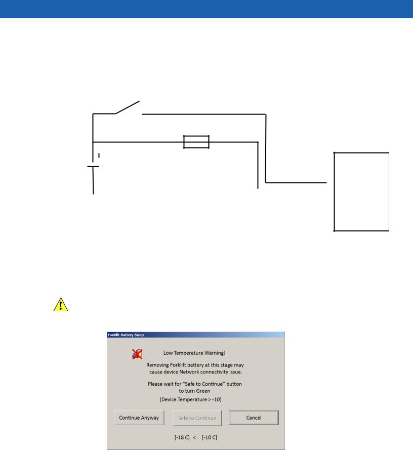
Forklifts and Trucks with 12V, 24V, 36V and 48V Batteries
•All power wiring must use the supplied 25-159551-01 power cable.
•One 3AB, 15A, 250V, FST BLO fuse.
•Keep the path between the battery and the vehicle computer as short as possible and away from any part of the ignition high tension system.
Yellow
Ignition Switch or Key Switch
15A Fuse
Red
Power Cable
25-159551-01 Vehicle  9-60V DC Battery
Black |
|
|
VC70 |
|
|
||
|
|
|
|
Important: If your vehicle is not equipped with an ignition or key switch, connect the yellow wire directly to the positive terminal of the vehicle’s battery. Failure to comply, will disenable the VC70 operation.
Figure 2-1 Wiring Diagram
You can use your old VC5090 power cable. When employing this option, use VC5090 Bridge Cable, PN 25-159553-01. You must also replace the fuses on the red and black wires of the old cable with the new fuses supplied with the bridge cable kit.
1.Disconnect the vehicle battery.
CAUTION To prevent damage to the VC70, replacing the vehicle battery is forbidden when the ambient
temperature is under -10 °C. Attempting to replace a battery under -10 °C will result in a warning shown on the VC70 screen and prevent the user from switching off the VC70. To replace the battery, move to a place with temperature is above -10 °C - the warning screen will disappear.
Figure 2-2 Forklift Battery Swap - Low Temperature Warning

2 - 4 VC70 Vehicle Computer Product Reference Guide
2.Connect the red wire directly to the vehicle's battery positive terminal. Connect the black wire directly to the vehicle's battery negative terminal.
NOTE The vehicle computer contains an Ignition Sense feature that detects when the ignition switch or key switch is turned off and shuts the vehicle computer down after a preprogrammed timeout. This feature allows the operator to use the vehicle computer for a predetermined time period after the ignition switch or key switch is turned off, then shuts the vehicle computer down automatically to prevent over-discharge of the forklift battery. The timeout period is adjustable by the user (see Ignition Sensing on page 2-5 for setting the timeout value). When the vehicle computer enters low power mode using the Ignition Sense feature, current draw from the vehicle battery is reduced to less than 15mA and the vehicle computer consumes current from it's internal battery. This feature provides the automatic shutoff functionality of an external relay, without requiring an actual relay and has the added benefit of allowing the user to work for a preset time period before shutting down.
NOTE For power drain of the forklift battery under the various power conditions, refer to Power Status on page 3-22.
NOTE See the vehicle Owner's Manual for specific wiring information.
3.Connect the yellow wire to the vehicle's ignition or key switch if such is used. If you do not plan on using the Ignition Sense feature, connect the yellow wire directly to the vehicle’s battery positive terminal.
4.Ensure the wiring connections created are sufficiently insulated from each other.
5.Re-connect the vehicle battery.
6.Connect the power cable connector into the vehicle computer's Power port. Align the keyway on the power connector with the notch on the vehicle computer’s power port.
7.If the power supply is mounted remotely from the VC70, use 25-159549-01 extender cable to connect between the power supply and the VC70.
8.Secure the power cables on both sides of the power supply with cable ties as close as possible to the connectors.
The VC70 display can be blanked when the vehicle is moving to eliminate driver distraction for safety
considerations (see Screen locking feature on page 11-6).
To recover from display lock:
1.Press and hold on touch screen (more than 1 second).
2.Remove your finger from the screen to resume operation.
Installation 2 - 5
Ignition Sensing
The vehicle computer contains an Ignition Sense feature that detects when the ignition switch or key switch is turned off and shuts the vehicle computer down after a preprogrammed timeout. This feature allows the operator to use the vehicle computer for a predetermined time period after the ignition switch or key switch is turned off, then shuts the vehicle computer down automatically to prevent over-discharge of the forklift battery. The timeout period is adjustable by the user. When the vehicle computer enters low power mode using the Ignition Sense feature, current draw from the vehicle battery is reduced to less than 15mA and the vehicle computer consumes current from it's internal battery. This feature provides the automatic shutoff functionality of an external relay, without requiring an actual relay and has the added benefit of allowing the user to work for a preset time period before shutting down.
The power cable must be connected to the ignition switch or key switch. See Forklifts and Trucks with 12V, 24V, 36V and 48V Batteries on page 2-3 for information on connecting the power cable to enable the Ignition Sense feature.
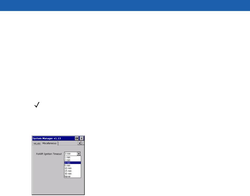
NOTE These settings are not persistent across a cold boot.
1.Tap  > Settings > Control Panel > VC70 System Manager icon. The System Manager window displays.
2.Select the Miscellaneous tab.
Figure 2-3 Miscellaneous Tab Window
3.In the Forklift Ignition Timeout drop-down list, select the amount of time before the vehicle computer shuts down after the ignition switch or key switch is turned off.
4.Tap OK.

2 - 6 VC70 Vehicle Computer Product Reference Guide
VC70 Power States
NOTE Refer to Power Status on page 3-22 for description of the various power states.
Table 2-1 describes the power drain of the forklift battery under various power conditions.
Table 2-1 VC70 Power States
Power |
Forklift |
Ignition |
Power |
Power Key |
Power State |
|
State |
battery |
Switch |
Description |
|||
|
|
Power On Connected
Connected
Low |
Connected |
|
Power |
||
|
Not
Connected
Critical |
Don't Care |
|
Suspend |
||
|
On |
On |
Not Pressed |
Pressed
On On (from Power
On State)
Off after inactivity timer expires
(programma On Not Pressed ble, 3
minutes default)
Don't Care |
On |
Pressed |
Don't Care |
Off |
Don't Care |
System on with full functionality.
System on with display, touch screen and audio off. (see Waking
the Vehicle Computer on page 3-23)
Reduced power consumption mod, external power turned off - 15mA current drain from forklift battery. System powered from internal battery. When the capacity of the internal battery is reduced to 50%, the device goes to Critical Suspend state.
System off. Unit in backupmode up to 72 hours.
Unit kept alive by internal backup battery.
Power drain from forklift battery
Typical when internal battery is not charging - 15W.
Typical during internal battery charging - 22W.
Maximum during operation - 100W.
No internal battery charging - 7.5W. Internal battery charging - 15W
External power supply idle current - 0.2W
External power supply idle current - 0.2W
Loading...