


User’s Guide
For Models S-300 and S-500
Zebra Technologies Corporation |
Zebra Technologies Europe Limited |
||
333 Corporate Woods Parkway |
Zebra House, The Valley Centre |
||
Vernon Hills, Illinois 60061-3109 |
Gordon Road, High Wycombe |
||
|
|
Buckinghamshire HP13 6EQ England |
|
Phone Number: (847) |
634-6700 |
Phone Number: |
+44 (0) 1494 472872 |
Telefax Number: (847) |
913-8766 |
Telefax Number: |
+44 (0) 1494 450103 |
Customer order # 44870L |
Manufacturer part # 44870LB Rev. 2 |
||
Proprietary Statement
This manual contains proprietary information of Zebra Technologies Corporation. It is intended solely for the information and use of parties operating and maintaining the equipment described herein. Such proprietary information may not be used, reproduced, or disclosed to any other parties for any other purpose without the expressed written permission of Zebra Technologies Corporation.
Product Improvements
Continuous improvement of products is a policy of Zebra Technologies Corporation. All specifications and signs are subject to change without notice.
FCC Compliance Statement
Note: This equipment has been tested and found to comply with the limits for a Class A digital Device, pursuant to Part 15 of the FCC Rules. These limits are designed to provide reasonable protection against harmful interference when the equipment is operated in a commercial environment. This equipment generates, uses and can radiate radio frequency energy and, if not installed and used in accordance with the instructions manual, may cause harmful interference to radio communications. Operation of this equipment in a residential area is likely to cause harmful interference in which case the user will be required to correct the interference at his own expense.
In order to insure compliance, this printer must be used with a Shielded Power Cord and Shielded Communication Cables.
“ The user is cautioned that any changes or modifications not expressly approved by Zebra Technologies Corporation could void the user’s authority to operate the equipment.”
Canadian DOC Compliance Statement
This digital apparatus does not exceed the Class A limits for radio noise emissions from digital apparatus as set out in the radio interference regulations of the Canadian Department of Communications.
Liability Disclaimer
Zebra Technologies Corporation takes steps to assure that its published Engineering specifications and Manuals are correct; however, errors do occur. Zebra Technologies Corporation has been advised of the possibility of such damages. Because some states do not allow the exclusion or limitation of liability for consequential or incidental damages, the above limitation may not apply to you.
Copyrights
This copyrighted manual and the label printer described herein are owned by Zebra Technologies Corporation. All rights are reserved. Unauthorized reproduction of this manual or the software in the label printer may result in imprisonment of up to one year and fines of up to $10,000 (17 U.S.C.506). Copyright violators may be subject to civil liability.
Centronicsâ is a registered trademark of Genicom Corporation IBMâ is a registered trademark of IBM Corporation
Zebra®, Stripe®, ZPL®, and ZPL II® are registered trademarks of Zebra Technologies Corporation
© Zebra Technologies Corporation

Warranty Information
1. Printer Warranty
ZEBRA® printers, excluding thermal printheads which are warranted separately below, are warranted against defects in material or workmanship for six (6) months from the date of original shipment by ZEBRA Technologies Corporation. This warranty does not cover normal wear and tear and shall be null and void if the equipment is modified, improperly installed or used, damaged by accident or neglect, or in the event any parts are improperly installed or replaced by the user.
Since printhead wear is part of normal operations, the original printhead and replacement printheads are covered by a limited warranty of six (6) months from the date of original shipment by ZEBRA Technologies. To qualify for this warranty, the printer must be returned to the factory or other authorized service center. Although the user is not required to purchase ZEBRA brand supplies (media and/or ribbons), to the extent it is determined that the use of other supplies (media and/or ribbons) shall have caused any defect in the thermal printhead for which a warranty claim is made, the user shall be responsible for ZEBRA Technologies’ customary charges for labor and materials to repair such defect. To the extent that it is determined that failure to follow the preventive maintenance schedule and procedures listed in the Operator’s Guide shall have caused any defect in the thermal printhead for which a warranty claim is made, this limited warranty shall be void.
ZEBRA TECHNOLOGIES’ SOLE OBLIGATION UNDER THIS WARRANTY SHALL BE TO FURNISH PARTS AND LABOR FOR THE REPAIR OR REPLACEMENT OF PRODUCTS FOUND TO BE DEFECTIVE IN MATERIAL OR WORKMANSHIP DURING THE WARRANTY PERIOD.
As a condition of this warranty, the user must: (a) obtain a ZEBRA Return Authorization for the printer, or subassembly(s); (b) ship the printer or subassembly(s), transportation prepaid to the authorized service location; and (c) include with the Product or subassembly(s) a written description of the claimed defect. Unless ZEBRA Technologies authorizes return of the entire Product, the user shall return only the subassembly(s). Products returned shall be packaged in the original packing and shipping container or comparable container. In the event equipment is not so packaged or if shipping damage is evident, it will not be accepted for service under warranty. Surface transportation charges for the return of the printer to the customer shall be paid by ZEBRA Technologies within the 48 contiguous states and the District of Columbia. Customer shall pay shipping costs, customs clearance, and other related charges outside the designated area. If ZEBRA Technologies determines that the Product returned to it for warranty service or replacement is not defective as herein defined, BUYER shall pay all costs of handling and transportation.
2. Supplies Warranty
ZEBRA supplies are warranted to be free from defects in materials or workmanship for a period of either the stated material shelf life or 6 months from date of shipment, whichever occurs first, provided that the BUYER has complied with ZEBRA Technologies’ guidelines on storage, handling, and usage of the labeling supplies in ZEBRA printers. ZEBRA Technologies does not warrant the performance of ZEBRA labeling supplies on non-ZEBRA printers.
Any supplies product shown to the satisfaction of ZEBRA Technologies, within the time provided, to be so defective shall be replaced without charge, or ZEBRA Technologies may issue a credit in such an amount as it deems reasonable.
3. Warranty Exclusions and Conditions
The above warranties are in lieu of all other warranties, expressed or implied, oral or written, statutory or otherwise, including any implied warranty of merchant-ability or fitness for a particular purpose.
ZEBRA Technologies shall not be responsible for the specific application to which any Products are applied, including but not limited to compatibility with other equipment.
i

Warranty Information
All statements, technical information and recommendations relating to ZEBRA Products are based upon tests believed to be reliable but do not constitute a guarantee or warranty.
ZEBRA TECHNOLOGIES SHALL NOT, UNDER ANY CIRCUMSTANCES WHATSOEVER, BE LIABLE TO BUYER OR ANY OTHER PARTY FOR LOST PROFITS, DIMINUTION OF GOOD WILL OR ANY OTHER SPECIAL OR CONSEQUENTIAL DAMAGES WHATSOEVER WITH RESPECT TO ANY CLAIM HEREUNDER. IN ADDITION, ZEBRA TECHNOLOGIES’ LIABILITY FOR WARRANTY CLAIMS SHALL NOT, IN ANY EVENT, EXCEED THE INVOICE PRICE OF THE PRODUCT CLAIMED DEFECTIVE, NOR SHALL ZEBRA TECHNOLOGIES BE LIABLE FOR DELAYS IN REPLACEMENT OR REPAIR OF PRODUCTS.
No salesperson, representative or agent of ZEBRA Technologies is authorized to make any guarantee, warranty, or representation in addition to the foregoing warranty.
NO WAIVER, ALTERATION, ADDITION, OR MODIFICATION OF THE FOREGOING WARRANTIES SHALL BE VALID UNLESS MADE IN WRITING AND SIGNED BY AN EXECUTIVE OFFICER OF ZEBRA TECHNOLOGIES.
Zebra Software License Agreement
The enclosed software and documentation are protected by the United States copyright law and international treaty, and therefore you must treat them like a book, with the exception that you may
make copies to protect yourself against loss of the original.
Your right to use the enclosed software and documentation as described below is non-exclusive and non-transferable. Zebra retains ownership in the software and documentation and all other right, title and interest. The enclosed software and documentation may be used by any number of people and may be freely moved from one computer to another as long as there is no possibility of their being used by more than one person on more than one computer at the same time.
Machine readable files representing graphics or fonts which you have created independently may be converted to ZPL format files using the enclosed software and such files may be used, copied onto
diskettes or font cards, given away, or sold without paying license fees to Zebra.
Pictorial or graphic images and machine readable files representing them may be protected by United States copyright law and international treaty provisions which prohibits you from transcribing or scanning such images or using copying, or converting such files without permission of the copyright owner. You may not use this software in violation of U.S. copyright law or international treaty. By
using this software, you agree to be bound by these terms.
Zebra Technologies Corporation (“ Zebra” ) warrants the enclosed diskette to be free of defects in material and workmanship for a period of 60 days from the date of purchase. In the event of notification within the warranty period of defects in material and workmanship, Zebra will replace the defective diskette or documentation. Zebra specifically disclaims all other warranties, expressed or implied, including but not limited to implied warranties of merchantability and fitness for a particular purpose. IN NO EVENT WILL ZEBRA TECHNOLOGIES BE LIABLE FOR LOST PROFITS, LOST DATA, OR ANY OTHER INCIDENTAL OR CONSEQUENTIAL DAMAGES CAUSED BY ABUSE OR MISAPPLICATION OF THE SOFTWARE OR BY ITS USE IN VIOLATION OF THE U.S. COPYRIGHT LAW OR INTERNATIONAL TREATY.
ii

Table of Contents
Warranty Information . . . . . . . . . . . . . . . . . . . . . . . . . . . . . . . . . . . . . . . . . . . . i Zebra Software License Agreement . . . . . . . . . . . . . . . . . . . . . . . . . . . . . . . . . ii
1 Getting Started
Unpacking . . . . . . . . . . . . . . . . . . . . . . . . . . . . . . . . . . . . . . . . . . . . . . . . . . . . . 1
Reporting Damage . . . . . . . . . . . . . . . . . . . . . . . . . . . . . . . . . . . . . . . . . . . . 1
Storage and Reshipping . . . . . . . . . . . . . . . . . . . . . . . . . . . . . . . . . . . . . . . . 2
Site Requirements . . . . . . . . . . . . . . . . . . . . . . . . . . . . . . . . . . . . . . . . . . . . . . . 2
Printer Power Up . . . . . . . . . . . . . . . . . . . . . . . . . . . . . . . . . . . . . . . . . . . . . . . . 2
Voltage Selection . . . . . . . . . . . . . . . . . . . . . . . . . . . . . . . . . . . . . . . . . . . . . 3
AC Power Cable . . . . . . . . . . . . . . . . . . . . . . . . . . . . . . . . . . . . . . . . . . . . . . 3
Communications . . . . . . . . . . . . . . . . . . . . . . . . . . . . . . . . . . . . . . . . . . . . . . . . 4
Cutter Module Interface. . . . . . . . . . . . . . . . . . . . . . . . . . . . . . . . . . . . . . . . . . . 4
Media and Ribbon . . . . . . . . . . . . . . . . . . . . . . . . . . . . . . . . . . . . . . . . . . . . . . . 5
Loading Media . . . . . . . . . . . . . . . . . . . . . . . . . . . . . . . . . . . . . . . . . . . . . . . 5
Tear-Off Mode Media Loading . . . . . . . . . . . . . . . . . . . . . . . . . . . . . . . . . . . . 5
Roll Media Loading . . . . . . . . . . . . . . . . . . . . . . . . . . . . . . . . . . . . . . . . . . . . . 5
Fanfold Media Loading . . . . . . . . . . . . . . . . . . . . . . . . . . . . . . . . . . . . . . . . . . 6
Cutter Mode Media Loading . . . . . . . . . . . . . . . . . . . . . . . . . . . . . . . . . . . . . . 6
External Rewind Mode Media Loading . . . . . . . . . . . . . . . . . . . . . . . . . . . . . . 6
Peel-Off Mode Media Loading. . . . . . . . . . . . . . . . . . . . . . . . . . . . . . . . . . . . . 8
Removing the Label Backing Material . . . . . . . . . . . . . . . . . . . . . . . . . . . . 9
Adjusting the Media Sensor. . . . . . . . . . . . . . . . . . . . . . . . . . . . . . . . . . . . . . . 10
Non-Continuous Media . . . . . . . . . . . . . . . . . . . . . . . . . . . . . . . . . . . . . . . 10
Continuous Media. . . . . . . . . . . . . . . . . . . . . . . . . . . . . . . . . . . . . . . . . . . . 10
Ribbon Loading . . . . . . . . . . . . . . . . . . . . . . . . . . . . . . . . . . . . . . . . . . . . . . . . 11
Adjusting the Ribbon Supply Spindle . . . . . . . . . . . . . . . . . . . . . . . . . . . . 11
Ribbon Supply Spindle: Normal Position . . . . . . . . . . . . . . . . . . . . . . . . . . . 11
Ribbon Supply Spindle: Low-Tension Position . . . . . . . . . . . . . . . . . . . . . . . 11
Loading the Ribbon . . . . . . . . . . . . . . . . . . . . . . . . . . . . . . . . . . . . . . . . . . 12
Ribbon Removal . . . . . . . . . . . . . . . . . . . . . . . . . . . . . . . . . . . . . . . . . . . . . . . 12
Initial Printer Test . . . . . . . . . . . . . . . . . . . . . . . . . . . . . . . . . . . . . . . . . . . . . . 13
Configuration and Calibration . . . . . . . . . . . . . . . . . . . . . . . . . . . . . . . . . . . . . 13
Option Switches . . . . . . . . . . . . . . . . . . . . . . . . . . . . . . . . . . . . . . . . . . . . . 13
Configuration Mode . . . . . . . . . . . . . . . . . . . . . . . . . . . . . . . . . . . . . . . . . . 14
Media Calibration . . . . . . . . . . . . . . . . . . . . . . . . . . . . . . . . . . . . . . . . . . . . . . 14
Adjust the Print Darkness . . . . . . . . . . . . . . . . . . . . . . . . . . . . . . . . . . . . . . . . 15
!
"
#
$
xi d n e p p
A
y r a s s ol
G
x e d n I
EEE

Table of Contents
Adjust the Media Rest Position . . . . . . . . . . . . . . . . . . . . . . . . . . . . . . . . . . . . 15 Adjust the Position of the Top of the Label. . . . . . . . . . . . . . . . . . . . . . . . . . . 15
2 Operation
Operating Your Zebra Stripe Printer . . . . . . . . . . . . . . . . . . . . . . . . . . . . . . . 17 Printer Operating Modes . . . . . . . . . . . . . . . . . . . . . . . . . . . . . . . . . . . . . . . . 17 Tear-Off Mode . . . . . . . . . . . . . . . . . . . . . . . . . . . . . . . . . . . . . . . . . . . . . 17 Peel-Off Mode. . . . . . . . . . . . . . . . . . . . . . . . . . . . . . . . . . . . . . . . . . . . . . 17 Cutter Mode. . . . . . . . . . . . . . . . . . . . . . . . . . . . . . . . . . . . . . . . . . . . . . . . 18 External Rewind Mode . . . . . . . . . . . . . . . . . . . . . . . . . . . . . . . . . . . . . . . 18 Operator Controls . . . . . . . . . . . . . . . . . . . . . . . . . . . . . . . . . . . . . . . . . . . . . . 18 AC Power ON/OFF Switch. . . . . . . . . . . . . . . . . . . . . . . . . . . . . . . . . . . . 18 Front Panel Keys . . . . . . . . . . . . . . . . . . . . . . . . . . . . . . . . . . . . . . . . . . . . 20 Front Panel Lights . . . . . . . . . . . . . . . . . . . . . . . . . . . . . . . . . . . . . . . . . . . . . 20 Printer Status Sensors . . . . . . . . . . . . . . . . . . . . . . . . . . . . . . . . . . . . . . . . . . 21 Sample ZPL II Label Formats . . . . . . . . . . . . . . . . . . . . . . . . . . . . . . . . . . . . 23 Format 1: Simple Text and a Barcode . . . . . . . . . . . . . . . . . . . . . . . . . . . 23 Format 2: Saving a Label Format As a Graphic Image . . . . . . . . . . . . . . 24 Format 3: Using a Serialized Data Field. . . . . . . . . . . . . . . . . . . . . . . . . . 24
3 Routine Care and Adjustment
Cleaning . . . . . . . . . . . . . . . . . . . . . . . . . . . . . . . . . . . . . . . . . . . . . . . . . . . . . 25
Cleaning the Exterior . . . . . . . . . . . . . . . . . . . . . . . . . . . . . . . . . . . . . . . . 25
Cleaning the Interior . . . . . . . . . . . . . . . . . . . . . . . . . . . . . . . . . . . . . . . . . 25
Cleaning the Printhead . . . . . . . . . . . . . . . . . . . . . . . . . . . . . . . . . . . . . . . 26
Cleaning the Cutter Module . . . . . . . . . . . . . . . . . . . . . . . . . . . . . . . . . . . 27
Lubrication . . . . . . . . . . . . . . . . . . . . . . . . . . . . . . . . . . . . . . . . . . . . . . . . . . . 32
AC Power Fuse Replacement. . . . . . . . . . . . . . . . . . . . . . . . . . . . . . . . . . . . . 32
Mechanical Adjustments . . . . . . . . . . . . . . . . . . . . . . . . . . . . . . . . . . . . . . . . 33
Print Quality Adjustments. . . . . . . . . . . . . . . . . . . . . . . . . . . . . . . . . . . . . 33
Toggle Pressure Adjustment . . . . . . . . . . . . . . . . . . . . . . . . . . . . . . . . . . . 34
Media Sensor Position Adjustment. . . . . . . . . . . . . . . . . . . . . . . . . . . . . . 35
Backing Rewind Power Roller Adjustment . . . . . . . . . . . . . . . . . . . . . . . 35
Battery Replacement. . . . . . . . . . . . . . . . . . . . . . . . . . . . . . . . . . . . . . . . . . . . 36
4 Troubleshooting and Diagnostics
Troubleshooting Table . . . . . . . . . . . . . . . . . . . . . . . . . . . . . . . . . . . . . . . . . . 37
Printer Diagnostics . . . . . . . . . . . . . . . . . . . . . . . . . . . . . . . . . . . . . . . . . . . . . 41
Power-On Self Test . . . . . . . . . . . . . . . . . . . . . . . . . . . . . . . . . . . . . . . . . . 41
Additional Printer Self Tests. . . . . . . . . . . . . . . . . . . . . . . . . . . . . . . . . . . 41
EL

Table of Contents
CANCEL Key Self Test . . . . . . . . . . . . . . . . . . . . . . . . . . . . . . . . . . . . . . . . . 42
PAUSE Key Self Test. . . . . . . . . . . . . . . . . . . . . . . . . . . . . . . . . . . . . . . . . . . 42
FEED Key Self Test . . . . . . . . . . . . . . . . . . . . . . . . . . . . . . . . . . . . . . . . . . . . 43
MODE Key Self Test . . . . . . . . . . . . . . . . . . . . . . . . . . . . . . . . . . . . . . . . . . . 44
FEED Key and PAUSE Key. . . . . . . . . . . . . . . . . . . . . . . . . . . . . . . . . . . . . . 44
Extended Printer Diagnostics . . . . . . . . . . . . . . . . . . . . . . . . . . . . . . . . . . . 44
5 Specifications
General Specifications . . . . . . . . . . . . . . . . . . . . . . . . . . . . . . . . . . . . . . . . . . . 45
Printing Specifications. . . . . . . . . . . . . . . . . . . . . . . . . . . . . . . . . . . . . . . . . . . 45
Media Specifications . . . . . . . . . . . . . . . . . . . . . . . . . . . . . . . . . . . . . . . . . . . . 46
Ribbon Specifications . . . . . . . . . . . . . . . . . . . . . . . . . . . . . . . . . . . . . . . . . . . 46
Media Handling . . . . . . . . . . . . . . . . . . . . . . . . . . . . . . . . . . . . . . . . . . . . . . . . 46
Operator Controls. . . . . . . . . . . . . . . . . . . . . . . . . . . . . . . . . . . . . . . . . . . . . . . 46
Options . . . . . . . . . . . . . . . . . . . . . . . . . . . . . . . . . . . . . . . . . . . . . . . . . . . . . . . 47
Zebra Programming Language (ZPL II® ) . . . . . . . . . . . . . . . . . . . . . . . . . . . . 47
Bar Codes . . . . . . . . . . . . . . . . . . . . . . . . . . . . . . . . . . . . . . . . . . . . . . . . . . . . . 47
Standard Printer Fonts . . . . . . . . . . . . . . . . . . . . . . . . . . . . . . . . . . . . . . . . . . . 48
Standard Printer Font Examples. . . . . . . . . . . . . . . . . . . . . . . . . . . . . . . . . 49
Optional Printer Fonts . . . . . . . . . . . . . . . . . . . . . . . . . . . . . . . . . . . . . . . . . . . 50
Optional Printer Font Examples . . . . . . . . . . . . . . . . . . . . . . . . . . . . . . . . . 51
6 Support Services
How to Reach Us . . . . . . . . . . . . . . . . . . . . . . . . . . . . . . . . . . . . . . . . . . . . . . . 53 Technical Support . . . . . . . . . . . . . . . . . . . . . . . . . . . . . . . . . . . . . . . . . . . . . . 53 Zebra Technical Support Bulletin Board Service . . . . . . . . . . . . . . . . . . . 53 Technical Support Service via Telephone . . . . . . . . . . . . . . . . . . . . . . . . . 54 Technical Support via Mail or Fax. . . . . . . . . . . . . . . . . . . . . . . . . . . . . . . 54 Product Service and Support Programs . . . . . . . . . . . . . . . . . . . . . . . . . . . . . 56 Select The Program That Fits Your Business . . . . . . . . . . . . . . . . . . . . . . 56 Extended Factory Service Agreement . . . . . . . . . . . . . . . . . . . . . . . . . . . . 56 Third Party Support And Maintenance . . . . . . . . . . . . . . . . . . . . . . . . . . . 56
Zebra Solution Center and National Sales and Service
Center Support . . . . . . . . . . . . . . . . . . . . . . . . . . . . . . . . . . . . . . . . . . . . . . . . 56 Wang Customer Services Division . . . . . . . . . . . . . . . . . . . . . . . . . . . . . . . . . 57
Zebra Factory Services . . . . . . . . . . . . . . . . . . . . . . . . . . . . . . . . . . . . . . . . 57 User Self Maintenance . . . . . . . . . . . . . . . . . . . . . . . . . . . . . . . . . . . . . . . . 57 International Service and Support . . . . . . . . . . . . . . . . . . . . . . . . . . . . . . . 58 Zebra Training Programs . . . . . . . . . . . . . . . . . . . . . . . . . . . . . . . . . . . . . . . . . 59 Operations and Maintenance Courses . . . . . . . . . . . . . . . . . . . . . . . . . . . . 60
!
"
#
$
xi d n e p p
A
y r a s s ol
G
x e d n I
L

Table of Contents
Bar Codes at Work . . . . . . . . . . . . . . . . . . . . . . . . . . . . . . . . . . . . . . . . . . 61
Labeling. . . . . . . . . . . . . . . . . . . . . . . . . . . . . . . . . . . . . . . . . . . . . . . . . . . 61
Appendix
Adjusting the Printhead . . . . . . . . . . . . . . . . . . . . . . . . . . . . . . . . . . . . . . . . . 63
Printer Interface Technical Information. . . . . . . . . . . . . . . . . . . . . . . . . . . . . 66
RS-232 Interface . . . . . . . . . . . . . . . . . . . . . . . . . . . . . . . . . . . . . . . . . . . . 66
Signal Levels . . . . . . . . . . . . . . . . . . . . . . . . . . . . . . . . . . . . . . . . . . . . . . . . . . 66
Hardware Control Signal Descriptions . . . . . . . . . . . . . . . . . . . . . . . . . . . . . . 67
RS-232 Cabling Requirements . . . . . . . . . . . . . . . . . . . . . . . . . . . . . . . . . 67
Interconnect To DTE Devices . . . . . . . . . . . . . . . . . . . . . . . . . . . . . . . . . . . . . 67
Interconnect To DCE Devices . . . . . . . . . . . . . . . . . . . . . . . . . . . . . . . . . . . . . 67
Parallel Interface. . . . . . . . . . . . . . . . . . . . . . . . . . . . . . . . . . . . . . . . . . . . . . . 68
Parallel Cabling Requirements . . . . . . . . . . . . . . . . . . . . . . . . . . . . . . . . . 68
Signal Descriptions . . . . . . . . . . . . . . . . . . . . . . . . . . . . . . . . . . . . . . . . . . 69
Glossary
. . . . . . . . . . . . . . . . . . . . . . . . . . . . . . . . . . . . . . . . . . . . . . . . . . . . . . . . . . . . . 71
Index
. . . . . . . . . . . . . . . . . . . . . . . . . . . . . . . . . . . . . . . . . . . . . . . . . . . . . . . . . . . . . 73
LE

1 |
Getting Started |
1
Congratulations! You have just purchased a high-quality thermal demand printer manufactured by the industry leader in quality, service, and value—Zebra Technologies Corporation. For over 25 years, Zebra has provided customers with the highest caliber of products and support.
This manual provides all of the information you will need to operate your printer on a daily basis. To create label formats, refer to the ZPL II Programming Guide (part # 46469L—if you did not order one with your printer, it is available free by sending in the postcard at the front of this manual).
There is also a two-volume maintenance manual for this printer. Volume 1: General Maintenance (part # 44868L) contains the information you may need in order to maintain your printer, and Volume 2: Circuit Descriptions and Electrical Schematics
(part # 44869L) contains information necessary for repairing the circuit boards at the component level. You may order both volumes by specifying part # 44452L.
Unpacking
Save the carton and all packing materials in case shipping is ever required.
Inspect the printer for possible damage incurred during shipment.
∙Check all exterior surfaces for damage.
∙Raise the Media Access Door and inspect the Media Compartment for damage to components.
Reporting Damage
If you discover shipping damage upon inspection:
∙Immediately notify the shipping company of the damage.
∙Retain all packaging material for shipping company inspection.
∙File a damage report with the shipping company and notify your local distributor and Zebra Technologies Corporation of the damage.
Zebra Technologies Corporation is not responsible for any damage incurred during shipment of the equipment and will not repair this damage under warranty. Immediate notification of damage to the shipping company or its insuring agency will generally result in ensuring any damage claim validity and ultimate monetary compensation.
1

Getting Started
Storage and Reshipping
If you are not placing the Zebra Stripe Printer into operation immediately, repackage it using the original packing materials. The Zebra Stripe Printer may be stored under the following conditions.
∙Temperature: -40° to 140° F (-20 to 60° C)
∙Relative humidity: 5% to 85% non-condensing
To ship the Zebra Stripe Printer, carefully pack it in a suitable container to avoid damage during transit. Whenever possible, use the original container from the factory. A shipping container can be purchased from Zebra Technologies Corporation, if the original one is lost or destroyed.
If you use a different container, package the printer carefully to avoid damage.
CAUTION: When packaging the printer in a rigid container, use shock mounts or shock-absorbing packing material. A rigid container will allow shock on the outside to be transmitted undamped to the printer which may cause damage. Also, before packing, remove all ribbon and media from the supply and take-up spindles to prevent damage to the printer.
Site Requirements
CAUTION: To insure that the printer has proper ventilation and cooling, do not place any padding or cushioning material under the unit, because this restricts air flow.
The Zebra Stripe Printer may be installed on any solid, level surface of sufficient size and strength to accommodate the physical dimensions and weight of the unit. The area enclosure in which the printer will operate must meet the environmental conditions specified. Electrical power must be available and in close proximity to the printer.
Since the Zebra Stripe Printer was designed and is fabricated as an industrial-type unit, it will function satisfactorily in areas such as warehouses, factory floors, and office environments that conform to specified environmental and electrical conditions.
Printer Power Up
WARNING!! Check the AC voltage requirements for the printer before connecting it to a source of electrical power.
Follow the instructions in this section to connect this printer to a source of electrical power and a data communication cable.
2
Getting Started
Voltage Selection
The Stripe is available from the factory preset for either 100-120 VAC electrical power or 220-240 VAC electrical power. Refer to the product label on the back of the printer and make sure that the unit is properly configured for your power requirements.
AC Power Cable
The AC Power Cable has a three-prong female connector on one end. See Figure 2. This connector must be plugged into the mating connector on the left side of the printer. See Figure 1.
The electrical connection at the other end of the AC Power Cable will be one of the following:
∙US Standard 110 VAC three-prong plug
∙Great Britain Standard 220 VAC three-prong plug
∙European Standard 220 VAC three-prong plug
WARNING!! For personnel and equipment safety, always use a three-prong plug with an earth ground connection.
Insure that the AC Power ON/OFF Switch is in the OFF (0) position before connecting the AC Power Cable to a nearby electrical outlet.
1
Figure 1 Cable Connections
Figure 2 AC Power Cable
3

Getting Started
Communications
The Stripe comes with either an Electronics Industries Association (EIA) RS-232 serial data interface or a factory-installed parallel interface. In both cases, you must supply the required interface cable for your application. See the Appendix for specific cable requirements.
CAUTION: Zebra printers comply with FCC “ Rules and Regulations” , Part 15, Subpart J, for Class A Equipment, using fully shielded six-foot data cables. Use of longer cables or unshielded cables may increase radiated emissions above the Class A limits.
Cutter Module Interface (For Stripes with the Factory-Installed Cutter Option)
The Cutter Module connects to the printer via a standard 8-pin connector.
The cable on the front of the printer plugs into the connector on the bottom of the Cutter Module once the Cutter Module has been installed.
4
G e t t i n g S t a r t e d
|
RIBBON RELEASE |
RIBBON |
|
|
|
|
|
HEAD |
|
BUTTON |
SUPPLY |
|
|
||
|
|
|
|
OPEN |
|
|
|
LEVER |
OPEN |
|
MEDIA |
|
|
|
SUPPLY |
PRINTHEAD |
|
PRINTHEAD |
|
SHOWN |
|
ASSEMBLY |
|
OPEN |
|
|
MEDIA |
|
|
|
SUPPLY |
|
|
|
GUIDE |
|
MEDIA |
MEDIA |
MEDIA |
|
SENSOR |
||
|
|
SUPPLY |
|
|
ASSEMBLY |
GUIDE |
|
|
|
|
HANGER |
1
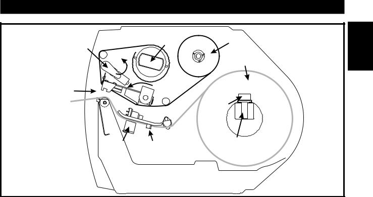
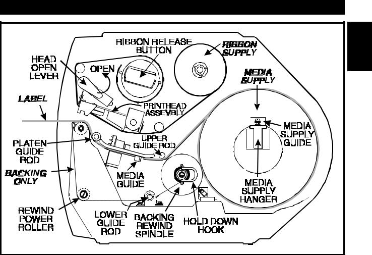
Figure 3 Roll Media Loading in Tear-Off Mode
Media and Ribbon
Loading Media
NOTE: A Media Calibration must be performed when media and ribbon (if used) are first installed in the printer, or when a different type of media or ribbon is installed. See page 14.
Media widths and thicknesses vary between applications. To maintain print quality from one application to another, refer to the Print Quality Adjustments section starting on page 33.
To load media, see Figures 3 through 6 and follow the loading procedure for your application.This section details the media and ribbon loading instructions for the printer. For detailed descriptions of the operating modes, see Chapter 2.
TearOff Mode Media Loading
Figures 3 and 4 illustrate the method of loading media for operation in Tear-Off Mode.
First, move the Head Open Lever counterclockwise to the OPEN position and raise the Printhead. Slide the Media Guide and the Media Supply Guide as far out from the printer frame as possible.
Roll Media Loading
Place the media roll on the Media Supply Hanger, and thread the media through the Printhead Assembly as shown in Figure 3. Adjust the Media Supply Guide and the Media Guide against the outer edge of the media. These guides must not cause pressure or excessive drag on the media. CLOSE the Head Open Lever, and see page 10 to adjust the Media Sensor position.
5

Getting Started
Fanfold Media Loading
Fanfold media, from outside the printer, feeds through either the bottom or rear access slot.
To load fanfold media, thread the media through the Printhead Assembly as shown in Figure 4. Adjust the Media Supply Guide and the Media Guide against the outer edge of the media. These Guides must not cause pressure or excessive drag on the media. CLOSE the Head Open Lever, and see page 10 to adjust the Media Sensor position.
Cutter Mode Media Loading (Cutter Option Required)
Figure 5 illustrates a Stripe printer equipped with the Cutter Option.
To ensure proper media loading, follow the directions for the Tear-Off Mode with the exception that the end of the media must be positioned on top of the Platen Roller. See Figure 5.
With the end of the media positioned directly on top of the platen roller, CLOSE the Head Open Lever. The printer will automatically feed out and cut one label when the printer is powered on.
External Rewind Mode Media Loading
NOTE: The Peel-Off Option is designed for the Peel-Off Mode only. It is not designed as an internal media rewind feature.
This operating mode requires an External Rewinder. Media loading is the same as for the Tear-Off Mode of operation. If an External Rewinder is used, follow the manufacturer’s operating instructions for that unit.
6

Getting Started
1 |
Figure 4 Fanfold Media Loading in Tear-Off Mode
Figure 5 Cutter Mode Media Loading
7

Peel-Off Mode Media Loading
Figure 6 illustrates an S-500 printer with the Peel-Off Option.
To insure proper media loading, see Figure 6 and follow the procedure below.
1.Slide the Media Supply Guide, Media Guide, and the Outer Edge Guides on both the Platen Guide Rod and the Lower Guide Rod as far out from the Printer Frame as possible.
2.Open the Head Open Lever and raise the Printhead Assembly.
3.Remove the Hold Down Hook.
4.Thread the media through the printhead as shown in Figure 6.
5.From the front of the printer, pull the media through the Printhead Assembly until approximately 24" of media extends out from the printer. Remove the labels from the backing of the 24" of media that extends from the front of the printer.
6.Align the inside edge of the media with the Edge Guide Mark near the left side of the Tear-Off/Peel-Off Plate, then close the Head Open Lever. (See Figure 15 on page 22 for a detailed illustration.)
7.Thread the backing behind the Lower Label Available Sensor, through the slot under the Rewind Power Roller, and below the Lower Guide Rod to the Backing Rewind Spindle. Then wind the backing material around the Backing Rewind Spindle 3 or 4 times in a counter-clockwise direction. To insure proper winding, press the edge of the backing material against the round plate at the far end of the Spindle.
8.To hold the media against the Spindle, place the Hold Down Hook over the backing and insert both ends into the small slots in the round plate at the far end of the Spindle. Again, rotate the Backing Rewind Spindle counterclockwise to remove any slack in the backing material.
9.Adjust all of the Guides:
∙Push the Media Supply Guide inward until it is just touching the outer side of the Media Supply Roll, then lock the guide in place with its locking screw. (The Guide must not cause pressure or excessive drag on the Media Supply Roll.)
∙Adjust the Outer Edge Guides on both the Lower Guide Rod and the Platen Guide Rod until they just touch the outer edge of the media and backing without causing the material to buckle.
∙Adjust the Media Guide until it just touches the outer edge of the media without causing the material to buckle.
10.See page 10 to adjust the Media Sensor.
In the Peel-Off Mode, proper media tracking is critical. Refer to the Backing Rewind Power Roller Adjustment on page 35 to make sure that the media tracks properly through the printer.
8
Getting Started
1 |
Figure 6 Peel-Off Mode Media Loading
Removing the Label Backing Material (Peel Off Option Required)
When the amount of backing wound on the Backing Rewind Spindle reaches full capacity, the Backing Rewind Spindle Full Sensor activates, the Paper/Ribbon light flashes, and printing pauses.
To remove the backing material, follow these steps (you don’t need to turn the printer Power OFF for this procedure):
1.Unwind about 24" of backing from the Backing Rewind Spindle and cut it off at the spindle.
2.Pull out the Hold Down Hook and slide the backing material off of the Spindle and discard.
3.Feed the new starting edge of the backing through the mechanism and attach it to the Backing Rewind Spindle as described in the loading procedure.
4.While holding the media in position against the Tear-Off/Peel-Off Plate, Open and Close the Printhead without disturbing the media position. The printer is now ready to print more labels.
9
Getting Started
Adjusting the Media Sensor
When the Stripe printer is powered ON, it performs a self test and configures its operating characteristics. Some of these characteristics are determined by the position of the Media Sensor. See Figure 7.
The Media Sensor Assembly consists of two sections. The media passes between a stationary light source and a movable light sensor. The light source is positioned below the media, while the light sensor
is positioned above the media.
This adjustment aligns the position of the light sensor with the notch or edge of the label.
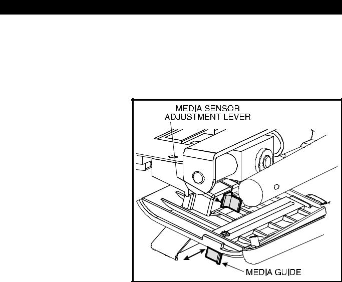
With the Printhead OPEN, look through the front of the print mechanism and locate the Media Sensor Adjustment Lever. Reposition the sensor until the top of the adjustment lever is in line with the notch in the media. CLOSE the printhead by moving the Head Open Lever to the CLOSED position.
When continuous media (no notch or opening to sense) is used, position the Media Sensor anywhere over the media so that an “ Out-of-Media” condition
will still be sensed. |
Figure 7 Media Sensor Adjustment |
|
Non-Continuous Media
This type of media has some type of physical characteristic (web, notch, perforation, etc.) which indicates the start/end of each label.
The Media Sensor must be properly positioned to sense these indicators. See “ Adjusting the Media Sensor” (above).
Continuous Media
Since continuous media does not contain label start/end indicators, you must tell the printer via software how long each label is. If you are using ZPL or ZPL II, include a Label Length (^LL) instruction in each label format you send to the printer (refer to your ZPL II Programming Guide). If you are using other software to drive your printer, refer to the instructions provided with that software.
Even with continuous media, you still need to position the Media Sensor in the middle of the media to sense when you run out of media.
10
Getting Started
Ribbon Loading
Adjusting the Ribbon Supply Spindle
Ribbon Supply Spindle: Normal Position
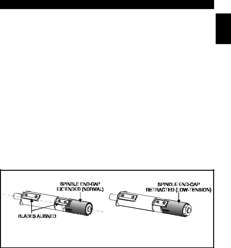
In the Normal Position, the “ Dual-Tension” Ribbon Supply Spindle provides the desired amount of ribbon back-tension for different ribbon widths.
To place the Spindle in the Normal Position, firmly pull the Spindle End-Cap until it clicks into place, as shown in Figure 8.
Ribbon Supply Spindle: Low-Tension Position
Low-Tension Position is used in limited applications with ribbons wider than 2.4" (60 mm) to provide lower ribbon back-tension. Low-Tension Position is only recommended when normal tension hampers the ribbon movement.
To put the Spindle in the Low-Tension Position, firmly push the Spindle End-Cap until it clicks into place, as shown in Figure 8.
1
Normal Position |
Low-Tension Position |
Figure 8 Ribbon Supply Spindle Adjustment
11
Getting Started
Figure 9 Ribbon Loading Diagram
Loading the Ribbon
To load ribbon, see Figure 9 and follow the procedure below.
Note: Use ribbon that is wider than the media. The smooth backing of the ribbon protects the printhead from wear and premature failure due to excessive abrasion.
For Direct Thermal Print Method, ribbon is not used and should not be loaded in the printer when performing the Media Calibration.
1.Adjust the Ribbon Supply Spindle position for normal or low tension. (see page 11).
2.Align the blades on the two sections of the spindle as shown in Figure 8. (You do not need to do this if your ribbon width is 2.4" (60 mm) or less.)
3.Place the ribbon roll on the Ribbon Supply Spindle.
4.Open the Printhead by moving the Head Open Lever counterclockwise to the OPEN position.
5.Thread the ribbon as shown without creasing or wrinkling it. Wind the ribbon onto the Ribbon Takeup Spindle for several turns in a clockwise direction.
6.Close the Printhead by moving the lever clockwise to the CLOSED position.
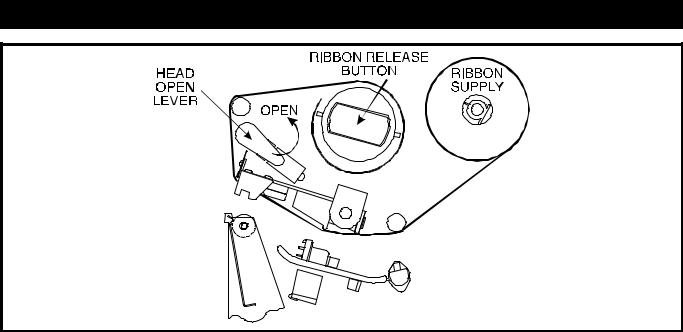
Ribbon Removal
Cut the ribbon where it is stretched between the Upper Ribbon Guide Arm and the Takeup Spindle. To remove ribbon from the Takeup Spindle, press the Release Button and slide the ribbon off the Spindle.
12
Getting Started
Initial Printer Test
To insure proper sensing of the media and ribbon, perform a Media Calibration. This procedure establishes the media parameters for the printer. If loading the printer with media and ribbon for the first time, or changing the type of media, perform the Media Calibration on page 14.
Configuration and Calibration
Option Switches (Only for Serial-Interface Printers)
Note: A printer with a parallel interface does not require these configuration parameters and therefore has no switches.
A printer with the RS-232 serial interface has eight miniature switches, which are located inside the rear access opening above the Signal Interface Cable Connector.
You need to position these switches to match the settings of your host computer in order to establish communications between the two devices. If you do not know how to determine the settings on your host computer, refer to the directions in the instruction manual provided with the computer.
If these switches are in the proper position to match the communication configuration of the host computer, and the printer is not receiving data, see the Appendix to make sure you are using the correct interface cable.
Figure 10 Option Switches
Option Switch Settings
An “R” means the switch is OFF (positioned to the right), while an “L” means the switch is ON (positioned to the left). Zebra sets all switches to OFF when the printer is manufactured.
Switch |
Baud Rate |
|
3 |
2 1 |
|
|
|
|
R R R |
9600 Baud |
|
R R L |
19200 Baud |
|
R L R |
110 Baud |
|
R L L |
300 Baud |
|
L R R |
600 Baud |
|
L R L |
1200 Baud |
|
L L R |
2400 Baud |
|
L L L |
4800 Baud |
|
|
|
|
Switch |
Data Bits |
|
|
4 |
(Must be set to 8 data bits for |
|
|
Code Page 850.) |
|
|
|
R |
7 Data bits |
|
L |
8 Data bits |
|
|
|
|
Switch |
Parity |
|
6 5 |
|
|
|
|
|
R R |
Even parity |
|
R |
L |
Parity disabled |
L R |
Odd parity |
|
L |
L |
Parity disabled |
|
|
|
Switch |
Communication Handshake |
|
|
7 |
Control |
|
|
|
R |
XON/XOFF control |
|
L |
DTR/DSR control |
|
|
|
|
13
1

Getting Started
Configuration Mode
The Configuration Mode allows you to fine-tune the internal printer configuration settings for your application. In this mode, you can change the following parameters:
∙Printing darkness
∙ Rest position of the media with respect to the “ web” or “ interlabel gap”
∙Position of printing relative to the top of the label
∙Media and Ribbon Sensor values
∙Label length
∙Printing method
∙Media type (continuous or non-continuous)
You can get a printout of the printer configuration (the values for each of these parameters) at any time by performing the CANCEL Key Self Test (see Chapter 4).
If it is ever necessary to reset the printer configuration to the factory defaults, refer to the “ FEED Key and PAUSE Key” Self Test description in Chapter 4.
The ZPL II Programming Guide contains information on instructions which may be sent to the printer to disable the MODE key and set specific label format values for each of these parameters. If you are not using ZPL II, refer to the instructions provided with the software you are using to determine if your software also allows you to change these parameters.
Media Calibration
IMPORTANT: Perform the Media Calibration Procedure when media is first installed, when a different type of media or ribbon is installed, or when print mode is changed.
During this procedure, the printer automatically determines the media type, label length, media and ribbon sensor settings, and printing method. Media type is determined by sensing either continuous or non-continuous media as blank labels move through the printer. If non-continuous media is sensed, Label Length is also calibrated. If ribbon is sensed, the Thermal Transfer Print Method is configured; otherwise, the Direct Thermal Print Method is configured.
The results of this calibration are stored in the printer’s memory and are retained even if printer power is removed. These parameters remain in effect until the next calibration is performed.
NOTE: If the printer is in the Peel-Off Mode, the operator must “catch” the labels as they are peeled away from the backing during this procedure.
1.Load media and ribbon (if used). Make sure the Media Sensor is properly positioned.
2.Place the Head Open Lever in the OPEN position.
14
|
Getting Started |
|
|
3. |
Turn the power switch ON. When the Power ON Self Test is complete, the |
|
|
|
|||
|
POWER and PAUSE lights will be ON and the PRINTHEAD light will FLASH. |
|
|
4. |
Press the MODE key 3 times briefly. PAUSE and CALIBRATE lights turn ON. |
1 |
|
|
|||
5. |
Close the Head Open Lever. |
|
|
6. |
Press UP to calibrate. The printer feeds some media. The MODE lights will flash |
|
|
|
|||
|
ON and OFF to indicate that the settings have been saved in memory. |
|
|
7. |
Press PAUSE to exit the PAUSE mode. The PAUSE light turns OFF. |
|
|
Adjust the Print Darkness
This procedure sets the darkness of the printing on the label. To maximize the life of the printhead, use the lowest setting which provides the necessary print quality.
1.Press the MODE key. PAUSE and DARKEN lights turn ON.
2.Press UP or DOWN to adjust the current setting.
3.Press the MODE key 3 times briefly. The MODE lights will flash ON and OFF to indicate that the settings have been saved in memory.
4.Press PAUSE to exit the PAUSE mode. The PAUSE light turns OFF.
Adjust the Media Rest Position
This procedure sets the end-of-label position relative to the Tear-Off Plate or Cutter. Adjust this if your label is not being torn or cut at the correct point.
1.Press the MODE key twice briefly. PAUSE and POSITION lights turn ON.
2.Press UP or DOWN to adjust the current setting.
3.Press the MODE key twice briefly. The MODE lights will flash ON and OFF to indicate that the settings have been saved in memory.
4.Press PAUSE to exit the PAUSE mode. The PAUSE light turns OFF.
Adjust the Position of the Top of the Label
This procedure positions the printing on the label relative to the top edge of the label. Adjust this if your printing is too close or too far away from the top or bottom edge of the label.
1.Press the MODE Key twice briefly then press and hold it for about 5 seconds until the lights change. The PAUSE, DARKEN, and CALIBRATE lights turn ON.
2.Press UP or DOWN to adjust the current setting.
3.Press the MODE key twice briefly. The MODE lights will flash ON and OFF to indicate that the settings have been saved in memory.
4.Press PAUSE to exit the PAUSE mode. The PAUSE light turns OFF.
15

Getting Started
16
 Loading...