


 Loading...
-7-Series AC Servo Drive
-7S/ -7W SERVOPACK with Hardware Option Specifications Dynamic Brake
Product Manual
SGD7S-020
SGD7W-020
Basic Information on SERVOPACKs
Selecting a SERVOPACK
Selecting a Dynamic Brake Resistor
Wiring and Connecting
a Dynamic Brake Resistor
Basic Functions That Require
Setting before Operation
Maintenance
Parameter Lists
Appendices
MANUAL NO. SIEP S800001 73B
1
2
3
4
5
6
7
8
9
10

Copyright © 2015 YASKAWA ELECTRIC CORPORATION
All rights reserved. No part of this publication may be reproduced, stored in a retrieval system, or transmitted, in any form, or by any means, mechanical, electronic, photocopying, recording, or otherwise, without the prior written permission of Yaskawa. No patent liability is assumed with respect to the use of the information contained herein. Moreover, because Yaskawa is constantly striving to improve its high-quality products, the information contained in this manual is subject to change without notice. Every precaution has been taken in the preparation of this manual. Nevertheless, Yaskawa assumes no responsibility for errors or omissions. Neither is any liability assumed for damages resulting from the use of the information contained in this publication.

About this Manual
This manual provides information on Σ-7-Series AC Servo Drives that support the dynamic brake hardware option specifications (SGD7-020). It describes the specifications of
SERVOPACKs that are different from the SERVOPACKs that do not support the dynamic brake hardware option specifications.
For all other information, refer to the product manual for a standard SERVOPACK.
Read and understand this manual and the standard SERVOPACK product manual to ensure correct usage of the Σ-7-Series AC Servo Drives.
Keep this manual and the standard SERVOPACK product manual in a safe place so that they can be referred to whenever necessary.
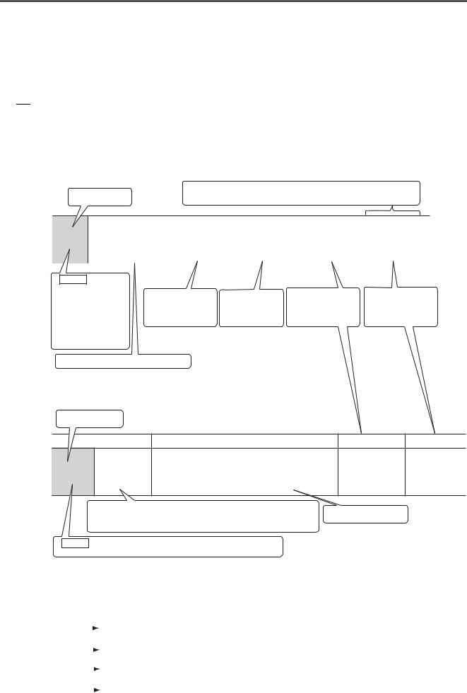
Finding Information
Information on SERVOPACKs that support the dynamic brake hardware option specifications is provided in different manuals depending on the topic. Use the following table to find what information is provided in this manual and what information is provided in the standard SERVOPACK product manual.
|
|
|
|
Σ-7S SERVOPACKs |
|
Σ-7W |
|
|
|
|
|
|
SERVOPACKs |
||
|
|
|
|
|
|
|
|
|
Item |
This |
Analog |
MECHA- |
Command Option |
MECHA- |
|
|
TROLINK-II/ |
Attachable |
TROLINK-III |
||||
|
Manual |
Voltage/ |
|||||
|
|
-III Commu- |
|
|
Communica- |
||
|
|
|
Pulse Train |
INDEXER |
DeviceNet |
||
|
|
|
nications |
tions |
|||
|
|
|
References |
Module |
Module |
||
|
|
|
References |
References |
|||
|
|
|
|
|
|
||
|
About the Dynamic |
|
|
|
|
|
|
|
Brake Hardware Option |
1.1 |
|
|
|
|
|
|
Specifications |
|
|
|
− |
|
|
Basic Informa- |
|
|
|
|
|
|
|
Nameplate |
1.2 |
|
|
|
|
||
tion on |
|
|
|
|
|
|
|
Part Names |
1.3 |
|
|
|
|
|
|
SERVOPACKs |
|
|
|
|
|
||
|
|
|
|
|
|
|
|
Model Designations |
1.4 |
|
|
|
|
|
|
|
|
|
|
|
|
||
|
|
|
|
|
|
|
|
|
Other basic information |
− |
|
|
Chapter 1 |
|
|
|
not listed above |
|
|
|
|
||
|
|
|
|
|
|
|
|
|
|
|
|
|
|
|
|
|
Combinations of Servo- |
|
|
|
|
|
|
|
motors and SERVO- |
2.1 |
|
|
− |
|
|
Selecting a |
PACKs |
|
|
|
|
|
|
|
|
|
|
|
|
||
|
|
|
|
|
|
|
|
SERVOPACK |
External Dimensions |
2.2 |
|
|
|
|
|
|
|
|
|
|
|
|
|
|
Other selection informa- |
− |
|
|
Chapter 2 |
|
|
|
tion not listed above |
|
|
|
|
||
|
|
|
|
|
|
|
|
|
|
|
|
|
|
|
|
Dynamic Brake Resistor Selection |
Chapter |
|
|
− |
|
|
|
3 |
|
|
|
|
|||
|
|
|
|
|
|
|
|
|
|
|
|
|
|
|
|
SERVOPACK Installation |
− |
|
|
Chapter 3 |
|
|
|
|
|
|
|
|
|
|
|
Wiring and Connecting SERVOPACKs |
|
|
Chapter 4 |
|
|
||
|
|
|
|
|
|||
|
|
|
|
|
|
|
|
Continued on next page.
iii

Continued from previous page.
|
|
|
|
|
Σ-7S SERVOPACKs |
|
Σ-7W |
|
|
|
|
|
|
|
SERVOPACKs |
||
|
|
|
|
|
|
|
|
|
|
Item |
This |
Analog |
|
MECHA- |
Command Option |
MECHA- |
|
|
|
TROLINK-II/ |
Attachable |
TROLINK-III |
||||
|
Manual |
Voltage/ |
|
|||||
|
|
|
-III Commu- |
|
|
Communica- |
||
|
|
|
Pulse Train |
|
INDEXER |
DeviceNet |
||
|
|
|
|
nications |
tions |
|||
|
|
|
References |
|
Module |
Module |
||
|
|
|
|
References |
References |
|||
|
|
|
|
|
|
|
||
Dynamic Brake Resistor Wiring and Con- |
Chapter |
|
|
|
|
|
|
|
nections |
|
4 |
|
|
|
|
|
|
|
|
|
|
|
|
|
|
|
|
Motor Stopping Methods |
|
|
|
|
|
|
|
|
for Servo OFF and |
5.2 |
|
|
|
|
|
|
|
Alarms |
|
|
|
|
|
|
|
|
|
|
|
|
|
− |
|
|
Basic Informa- |
Motor Stopping Method |
5.3 |
|
|
|
|
|
|
tion Required |
for Overtravel |
|
|
|
|
|
|
|
|
|
|
|
|
|
|
||
for Settings |
Setting the Energy Con- |
|
|
|
|
|
|
|
before Opera- |
sumption and Resis- |
5.4 |
|
|
|
|
|
|
tion |
tance of the Dynamic |
|
|
|
|
|
|
|
|
|
|
|
|
|
|
||
|
Resistor |
|
|
|
|
|
|
|
|
|
|
|
|
|
|
|
|
|
Other basic functions |
− |
|
|
|
Chapter 5 |
|
|
|
not listed above |
|
|
|
|
|
||
|
|
|
|
|
|
|
|
|
|
|
|
|
|
|
|
|
|
Application Functions |
|
|
|
|
Chapter 6 |
|
|
|
|
|
|
|
|
|
|
|
|
Trial Operation and Actual Operation |
|
|
|
|
Chapter 7 |
|
|
|
|
|
|
|
|
|
|
|
|
Tuning |
|
− |
|
|
|
Chapter 8 |
|
|
|
|
|
|
|
|
|
|
|
Monitor |
|
|
|
|
Chapter 9 |
|
|
|
|
|
|
|
|
|
|
||
|
|
|
|
|
|
|
||
Fully-Closed Loop Control |
|
|
|
Chapter 10 |
|
− |
||
|
|
|
|
|
|
|
|
|
Safety Control |
|
|
|
|
Chapter 11 |
|
||
|
|
|
|
|
|
|||
|
|
|
|
|
|
|
|
|
|
|
− |
|
− |
Chapters 12, |
Chapters 12, |
− |
|
Option Module Functions |
|
13, 14, and |
||||||
|
13, and 16 |
|||||||
|
|
|
|
|
|
17 |
|
|
|
|
|
|
|
|
|
|
|
|
|
|
|
|
|
|
|
|
|
Troubleshooting Related |
|
|
|
|
|
|
|
|
to the Dynamic Brake |
Chapter |
|
|
|
− |
|
|
|
Hardware Option Speci- |
6 |
|
|
|
|
|
|
Maintenance |
|
|
|
|
|
|
||
fications |
|
|
|
|
|
|
|
|
|
|
|
|
|
|
|
|
|
|
|
|
|
|
|
|
||
|
All other troubleshooting |
− |
Chapter 12 |
Chapter 15 |
Chapter 14 |
Chapter 10 |
||
|
|
|
|
|
|
|
|
|
Panel Displays and Panel Operator Pro- |
− |
Chapter 13 |
|
|
|
− |
|
|
cedures |
|
|
|
|
|
|||
|
|
|
|
|
|
|
|
|
|
|
|
|
|
|
|
|
|
|
Parameters Related to |
|
|
|
|
|
|
|
|
the Dynamic Brake Hard- |
Chapter |
|
|
|
− |
|
|
Parameter List |
ware Option Specifica- |
7 |
|
|
|
|
|
|
|
|
|
|
|
|
|||
|
tions |
|
|
|
|
|
|
|
|
|
|
|
|
|
|
|
|
|
All other parameters |
− |
Chapter 14 |
|
Chapter 13 |
Chapter 16 |
Chapter 15 |
Chapter 11 |
|
|
|
|
|
|
|
|
|
Interpreting the Panel Display |
|
– |
|
14.1 |
1.3 |
1.5 |
12.1 |
|
|
− |
|
|
|
|
|
|
|
Examples of Connections to Host Con- |
15.1 |
|
|
|
− |
|
||
trollers |
|
|
|
|
|
|
||
|
|
|
|
|
|
|
|
|
|
|
|
|
|
|
|
|
|
Corresponding SERVOPACK and |
− |
15.2 |
|
14.2 |
17.1 |
16.1 |
12.2 |
|
SigmaWin+ Function Names |
|
|||||||
|
|
|
|
|
|
|
||
|
|
|
|
|
|
|
|
|
Monitor Displays for the Dynamic Brake |
8.1 |
|
|
|
− |
|
|
|
Hardware Option Specifications |
|
|
|
|
|
|||
|
|
|
|
|
|
|
||
|
|
|
|
|
|
|
|
|
Coasting Distance when Stopping with |
8.2 |
|
|
|
|
|
|
|
the Dynamic Brake |
|
|
|
− |
|
|
||
|
|
|
|
|
|
|||
Data for Coasting Distance Calculation |
8.3 |
|
|
|
|
|
|
|
|
|
|
|
|
|
|
|
|
iv

Related Documents
The relationships between the documents that are related to the Servo Drives are shown in the following figure. The numbers in the figure correspond to the numbers in the table on the following pages. Refer to these documents as required.
Catalogs
Manuals
System
Machine
Controller and
Servo Drive
General
Catalog
Components
Machine Controllers Servo Drives
|
|
|
|
|
|
|
|
|
|
|
|
||
MP3300 |
|
|
Σ-7-Series |
|
||
Catalog |
|
|
Catalog |
|
||
|
|
|
|
|
|
|
|
|
|
|
|
|
|
Machine Controllers
|
|
|
|
|
|
|
|
|
|
|
|
|
|
|
|
|
|
|
|
|
|
|
|
|
|
|
|
|
|
|
|
|
|
|
|
|
|
|
|
|
|
|
|
|
|
|
|
|
|
|
|
|
|
|
|
|
|
|
|
|
|
|
|
|
|
|
|
|
|
|
|
|
|
|
|
|
|
|
|
|
|
|
|
|
|
|
|
|
|
|
|
|
|
|
SERVOPACKs with Built-in Controllers: Σ-7C |
||||||||||||||||||||||||
|
Built-in |
|
|
|
|
Option |
|
|
|
|
|||||||||||||||||||||||||||||
|
|
|
|
|
|
|
|
|
|
|
|
|
|
|
|
|
|
|
|
|
|
|
|
|
|
|
|
|
|
|
|||||||||
|
Function |
|
|
|
|
Module |
|
|
|
|
|
|
|
|
|
|
|
|
|
|
|
|
|
|
|
|
|
|
|
|
|
|
|||||||
|
|
|
|
|
|
|
|
|
|
|
|
|
|
|
|
|
|
|
|
|
|
|
|
|
|
|
|
|
|
|
|||||||||
|
|
|
|
|
|
|
|
|
User’s |
|
|
|
|
|
|
|
|
|
|
|
|
|
|
|
|
|
|
|
|
|
|
|
|
|
|
||||
|
Manuals |
|
|
|
|
Manuals |
|
|
|
|
|
|
|
|
|
|
|
|
|
|
|
|
|||||||||||||||||
|
|
|
|||||||||||||||||||||||||||||||||||||
|
|
|
|
|
|
|
|
|
|
|
|
|
|
|
|
|
|
Enclosed |
|
|
Σ- |
7-Series |
|
|
|
Built-in |
|||||||||||||
|
|
|
|
|
|
|
|
|
|
|
|
|
|
|
|
|
|||||||||||||||||||||||
|
|
|
|
|
|
|
|
|
|
|
|
|
|
|
|
|
|
Documents |
|
|
Σ- |
7C |
|
|
|
Function |
|||||||||||||
|
|
|
|
|
|
|
|
|
|
|
|
|
|
|
|
|
|
|
|
|
|
|
|
|
|
S |
ERVOPACK |
|
Manuals |
||||||||||
|
SERVOPACKs: Σ-7S and Σ-7W |
|
|
|
|
|
|
|
|
|
|
|
|
|
|
|
|
|
|||||||||||||||||||||
|
|
|
|
|
|
|
|
|
|
|
|
|
|
|
|
|
|
|
|
|
|
|
|
||||||||||||||||
|
|
|
|
|
|
|
|
|
|
|
|
|
|
|
|
|
|
|
|
|
|
|
|
|
|
Product Manual |
|
|
|||||||||||
|
|
|
|
|
|
|
|
|
|
|
|
|
|
|
|
|
|
|
|
|
|
|
|
|
|
||||||||||||||
|
|
|
|
|
|
|
|
|
|
|
|
|
|
|
|
|
|
|
|
|
|
|
|
|
|
|
|
|
|
|
|
|
|
|
|||||
|
|
|
|
|
|
|
|
|
|
|
|
|
|
|
|
|
|
|
|
|
|
|
|
|
|
|
|
|
|
|
|
|
|
|
|
|
|
|
|
|
|
|
|
|
|
|
|
|
|
|
|
|
|
|
|
|
|
|
|
|
|
|
|
|
|
|
|
|
|
|
|
|
|
|
|
|
|
|
|
|
|
|
|
|
|
|
|
|
|
|
|
|
|
|
|
|
|
|
|
|
|
|
|
|
|
|
|
|
|
|
|
|
|
|
|
||||
|
|
|
|
|
|
|
|
|
|
|
|
|
|
|
|
|
|
|
|
|
|
|
|
|
|
|
|
|
|
|
|
|
|
|
|
|
|||
|
Enclosed |
|
|
|
|
|
Σ-7-Series |
|
|
|
|
Σ-7-Series |
|
|
|
Σ-7-Series |
|
|
|||||||||||||||||||||
|
Documents |
|
|
|
|
|
Σ-7S/Σ-7W |
|
|
|
|
Σ-7S/Σ-7W |
|
|
|
|
|
|
Σ-7S/Σ-7W |
|
|
||||||||||||||||||
|
|
|
|
|
|
|
|
|
|
|
SERVOPACK |
|
|
|
|
SERVOPACK |
|
|
|
SERVOPACK |
|
|
|||||||||||||||||
|
|
|
|
|
|
|
|
|
|
|
|
|
|
|
|
|
|
|
|
|
Hardware Option |
|
|
|
FT/EX |
|
|
||||||||||||
|
|
|
|
|
|
|
|
|
|
|
Product |
|
|
|
|
Product Manuals |
|
|
|
|
|
|
|
|
|
|
|
|
|||||||||||
|
|
|
|
|
|
|
|
|
|
|
Manuals |
|
|
|
|
(such as this manual) |
|
|
Product Manuals |
|
|
||||||||||||||||||
|
|
|
|
|
|
|
|
|
|
|
|
|
|
|
|||||||||||||||||||||||||
|
|
|
|
|
|
|
|
|
|
|
|
|
|
|
|
|
|
|
|
|
|
|
|
|
|
|
|
|
|
|
|
|
|
|
|
|
|
|
|
Servomotors
Σ-7-Series Σ-7C SERVOPACK
Troubleshooting
Manual
Option
Module
User’s
Manual
|
|
|
|
|
|
|
|
|
|
|
|
|
|
|
Enclosed |
|
|
|
Σ-7-Series |
|
|
Documents |
|
|
|
Servomotor |
|
|
|
|
|
|
|
Product |
|
|
|
|
|
|
Manuals |
|
|
|
|
|
||
|
|
|
|
|
|
|
|
|
|
|
|
|
|
Other Documents
|
|
|
|
|
|
|
|
|
|
|
|
|
|
Σ-7-Series |
|
Σ-7-Series |
|
|
||
Peripheral |
|
MECHATROLINK |
|
|
||
Device |
|
Communications |
|
|
||
Selection |
|
Command |
|
|
||
Manuals |
|
|
||||
Manual |
|
|
|
|||
|
|
|||||
Programming
Manuals
Σ-7-Series Operation Interface
Operating
Manuals
Distributed
I/O Module
User’s
Manual
v

Classification |
Document Name |
Document No. |
Description |
|
|
|
|
Describes the features and applica- |
|
Machine Controller and |
|
tion examples for combinations of |
||
Machine Controller and |
|
|||
AC Servo Drive |
KAEP S800001 22 |
MP3000-Series Machine Control- |
||
Servo Drive |
||||
Solutions Catalog |
|
lers and Σ-7-Series AC Servo |
||
General Catalog |
|
|||
|
|
Drives. |
||
|
|
|
||
|
|
|
|
|
|
|
|
Provides detailed information on |
|
|
Machine Controller |
KAEP C880725 03 |
MP3300 Machine Controllers, |
|
MP3300 Catalog |
MP3300 |
including features and specifica- |
||
|
||||
|
|
|
tions. |
|
|
|
|
|
|
|
AC Servo Drives |
|
Provides detailed information on Σ- |
|
KAEP S800001 23 |
7-Series AC Servo Drives, including |
|||
Σ-7-Series Catalog |
Σ-7 Series |
|||
|
features and specifications. |
|||
|
|
|
||
|
|
|
|
|
|
Σ-7-Series AC Servo Drive |
|
Provides detailed information on |
|
|
|
the specifications, system configu- |
||
|
Σ-7C SERVOPACK |
SIEP S800002 03 |
ration, and application methods of |
|
|
Motion Control |
the Motion Control Function Mod- |
||
|
|
|||
|
User’s Manual |
|
ules (SVD, SVC4, and SVR4) for Σ- |
|
|
|
|
7-Series Σ-7C SERVOPACKs. |
|
|
|
|
Provides detailed information on |
|
Built-in Function Manuals |
|
|
the specifications, system configu- |
|
|
Machine Controller |
|
ration, and communications con- |
|
|
MP3000 Series |
SIEP C880725 12 |
nection methods for the Ethernet |
|
|
Communications |
communications that are used with |
||
|
|
|||
|
User’s Manual |
|
MP3000-Series Machine Control- |
|
|
|
|
lers and Σ-7-Series Σ-7C SERVO- |
|
|
|
|
PACKs. |
|
|
|
|
|
|
|
Machine Controller |
|
|
|
|
MP2000 Series |
SIEP C880700 04 |
|
|
|
Communication Module |
|
||
|
|
|
||
|
User’s Manual |
|
Provide detailed information on the |
|
|
|
|
||
|
Machine Controller |
|
||
|
|
specifications and communica- |
||
|
MP2000 Series |
|
||
|
SIEP C880700 36 |
tions methods for the Communica- |
||
|
262IF-01 FL-net |
|||
|
tions Modules that can be mounted |
|||
|
Communication Module |
|
||
|
|
to MP3000-Series Machine Con- |
||
|
User’s Manual |
|
||
|
|
trollers and Σ-7-Series Σ-7C |
||
|
|
|
||
|
Machine Controller |
|
||
|
|
SERVOPACKs. |
||
|
MP2000 Series |
|
|
|
|
263IF-01 EtherNet/IP |
SIEP C880700 39 |
|
|
|
Communication Module |
|
|
|
Option Module |
User’s Manual |
|
|
|
User’s Manuals |
Machine Controller |
|
|
|
|
MP2000 Series |
SIEP C880700 34 |
|
|
|
I/O Module |
|
||
|
|
|
||
|
User’s Manual |
|
Provide detailed information on the |
|
|
|
|
||
|
Machine Controller |
|
||
|
|
specifications and communica- |
||
|
MP2000 Series |
|
||
|
|
tions methods for the I/O Modules |
||
|
Analog Input/Analog Output |
SIEP C880700 26 |
||
|
that can be mounted to MP3000- |
|||
|
Module AI-01/AO-01 |
|
||
|
|
Series Machine Controllers and Σ- |
||
|
User’s Manual |
|
||
|
|
7-Series Σ-7C SERVOPACKs. |
||
|
|
|
||
|
Machine Controller |
|
||
|
|
|
||
|
MP2000 Series |
SIEP C880700 27 |
|
|
|
Counter Module CNTR-01 |
|
||
|
|
|
||
|
User’s Manual |
|
|
|
|
|
|
|
|
|
|
|
Continued on next page. |
vi

|
|
|
Continued from previous page. |
|
Classification |
Document Name |
Document No. |
Description |
|
|
Σ-7-Series AC Servo Drive |
|
Provides detailed information for |
|
|
Σ-7S and Σ-7W SERVOPACK |
TOMP C710828 00 |
the safe usage of Σ-7-Series |
|
|
Safety Precautions |
|
SERVOPACKs. |
|
|
Σ-V-Series/Σ-V-Series |
|
|
|
|
for Large-Capacity Models/ |
|
Provides detailed information for |
|
|
Σ-7-Series |
TOBP C720829 00 |
||
|
the safe usage of Option Modules. |
|||
|
Safety Precautions |
|
||
|
|
|
||
|
Option Module |
|
|
|
|
|
|
|
|
|
Σ-V-Series/Σ-V-Series |
|
Provides detailed procedures for |
|
|
for Large-Capacity Models/ |
|
||
|
Σ-7-Series |
TOBP C720829 01 |
installing the Command Option |
|
|
Installation Guide |
|
Module in a SERVOPACK. |
|
|
Command Option Module |
|
|
|
|
|
|
|
|
|
Σ-V-Series/Σ-V-Series |
|
|
|
|
for Large-Capacity Models/ |
|
Provides detailed procedures for |
|
|
Σ-7-Series |
TOBP C720829 03 |
installing the Fully-closed Module in |
|
Installation Guide |
|
a SERVOPACK. |
||
Enclosed Documents |
Fully-closed Module |
|
|
|
|
|
|
|
|
|
Σ-V-Series/Σ-V-Series |
|
|
|
|
for Large-Capacity Models/ |
|
Provides detailed procedures for |
|
|
Σ-7-Series |
TOBP C720829 06 |
installing the Safety Module in a |
|
|
Installation Guide |
|
SERVOPACK. |
|
|
Safety Module |
|
|
|
|
|
|
|
|
|
Σ-V-Series/Σ-V-Series |
|
|
|
|
for Large-Capacity Models/ |
|
Provides detailed procedures for |
|
|
Σ-7-Series |
TOBP C720829 02 |
installing the INDEXER Module in a |
|
|
Installation Guide |
|
SERVOPACK. |
|
|
INDEXER Module |
|
|
|
|
|
|
|
|
|
Σ-V-Series/Σ-V-Series |
|
|
|
|
for Large-Capacity Models/ |
|
Provides detailed procedures for |
|
|
Σ-7-Series |
TOBP C720829 07 |
installing the DeviceNet Module in a |
|
|
Installation Guide |
|
SERVOPACK. |
|
|
DeviceNet Module |
|
|
|
|
|
|
|
|
|
|
|
Provides detailed information on |
|
|
Σ-7-Series AC Servo Drive |
|
selecting Σ-7-Series Σ-7C SERVO- |
|
|
PACKs; installing, connecting, set- |
|||
Σ-7-Series |
|
|||
Σ-7C SERVOPACK |
SIEP S800002 04 |
ting, testing in trial operation, and |
||
Σ-7C SERVOPACK |
||||
Product Manual |
|
tuning Servo Drives; writing, moni- |
||
Product Manual |
|
|||
|
|
toring, and maintaining programs; |
||
|
|
|
||
|
|
|
and other information. |
|
|
|
|
|
|
Σ-7-Series |
Σ-7-Series AC Servo Drive |
|
Provides detailed troubleshooting |
|
Σ-7C SERVOPACK |
Σ-7C SERVOPACK |
SIEP S800002 07 |
information for Σ-7-Series Σ-7C |
|
Troubleshooting |
Troubleshooting Manual |
|
SERVOPACKs. |
|
Manual |
|
|
|
|
|
|
|
|
|
|
|
|
Continued on next page. |
vii

|
|
|
Continued from previous page. |
|
Classification |
Document Name |
Document No. |
Description |
|
|
Σ-7-Series AC Servo Drive |
|
|
|
|
Σ-7S SERVOPACK with |
|
|
|
|
MECHATROLINK-III |
SIEP S800001 28 |
|
|
|
Communications References |
|
|
|
|
Product Manual |
|
|
|
|
|
|
|
|
|
Σ-7-Series AC Servo Drive |
|
|
|
|
Σ-7S SERVOPACK with |
|
|
|
|
MECHATROLINK-II |
SIEP S800001 27 |
|
|
|
Communications References |
|
|
|
|
Product Manual |
|
|
|
|
|
|
|
|
|
Σ-7-Series AC Servo Drive |
|
|
|
|
Σ-7S SERVOPACK with |
SIEP S800001 26 |
|
|
|
Analog Voltage/Pulse Train |
Provide detailed information on |
||
|
References |
|
||
|
selecting Σ-7-Series SERVO- |
|||
Σ-7-Series |
Product Manual |
|
||
|
PACKs and information on install- |
|||
Σ-7S/Σ-7W |
|
|
||
|
|
ing, connecting, setting, performing |
||
SERVOPACK |
Σ-7-Series AC Servo Drive |
|
||
|
trial operation for, tuning, and mon- |
|||
Product Manuals |
Σ-7S SERVOPACK |
|
||
SIEP S800001 64 |
itoring the Servo Drives. |
|||
|
Command Option Attachable |
|||
|
|
|||
|
Type with INDEXER Module |
|
|
|
|
Product Manual |
|
|
|
|
|
|
|
|
|
Σ-7-Series AC Servo Drive |
|
|
|
|
Σ-7S SERVOPACK |
SIEP S800001 70 |
|
|
|
Command Option Attachable |
|
||
|
Type with DeviceNet Module |
|
|
|
|
Product Manual |
|
|
|
|
|
|
|
|
|
Σ-7-Series AC Servo Drive |
|
|
|
|
Σ-7W SERVOPACK with |
SIEP S800001 29 |
|
|
|
MECHATROLINK-III |
|
||
|
Communications References |
|
|
|
|
Product Manual |
|
|
|
|
|
|
|
|
|
Σ-7-Series AC Servo Drive |
|
|
|
|
Σ-7S/Σ-7W SERVOPACK with |
|
|
|
|
Hardware Option Specifica- |
This manual |
|
|
tions |
(SIEP S800001 73) |
|
||
Σ-7-Series |
Dynamic Brake |
|
|
|
Σ-7S/Σ-7W |
Product Manual |
|
Provide detailed information on |
|
SERVOPACK with |
|
|
Hardware Options for Σ-7-Series |
|
Σ-7-Series AC Servo Drive |
|
|||
Hardware Option |
|
SERVOPACKs. |
||
Σ-7W/Σ-7C SERVOPACK with |
|
|||
Specifications |
|
|
||
Hardware Option Specifica- |
|
|
||
Product Manuals |
SIEP S800001 72 |
|
||
tions |
|
|||
|
|
|
||
|
HWBB Function |
|
|
|
|
Product Manual |
|
|
|
|
|
|
|
|
|
|
|
Continued on next page. |
viii

|
|
|
Continued from previous page. |
|
Classification |
Document Name |
Document No. |
Description |
|
|
Σ-7-Series AC Servo Drive |
|
|
|
|
Σ-7S SERVOPACK with |
SIEP S800001 84 |
|
|
|
FT/EX Specification for Index- |
|
||
|
ing Application |
|
|
|
|
Product Manual |
|
|
|
|
|
|
|
|
|
Σ-7-Series AC Servo Drive |
|
|
|
|
Σ-7S SERVOPACK with |
|
|
|
|
FT/EX Specification for Track- |
SIEP S800001 89 |
|
|
|
ing Application |
|
|
|
|
Product Manual |
|
|
|
|
|
|
|
|
|
Σ-7-Series AC Servo Drive |
|
|
|
|
Σ-7S SERVOPACK with |
|
|
|
|
FT/EX Specification |
|
|
|
|
for Application with Special |
SIEP S800001 91 |
|
|
|
Motor, |
|
|
|
|
SGM7D Motor |
|
|
|
|
Product Manual |
|
|
|
|
|
|
|
|
|
Σ-7-Series AC Servo Drive |
|
|
|
|
Σ-7S SERVOPACK with |
|
|
|
Σ-7-Series |
FT/EX Specification |
SIEP S800001 94 |
Provide detailed information on the |
|
Σ-7S/Σ-7W SERVOPACK |
for Press and Injection |
FT/EX Option for Σ-7-Series |
||
|
||||
FT/EX |
Molding Application |
|
SERVOPACKs. |
|
Product Manuals |
Product Manual |
|
|
|
|
|
|
|
|
|
Σ-7-Series AC Servo Drive |
|
|
|
|
Σ-7S SERVOPACK with |
|
|
|
|
FT/EX Specification |
SIEP S800001 95 |
|
|
|
for Transfer and Alignment |
|
||
|
|
|
||
|
Application |
|
|
|
|
Product Manual |
|
|
|
|
|
|
|
|
|
Σ-7-Series AC Servo Drive |
|
|
|
|
Σ-7S SERVOPACK with |
|
|
|
|
FT/EX Specification |
SIEP S800002 09 |
|
|
|
for Torque/Force Assistance |
|
||
|
|
|
||
|
for Conveyance Application |
|
|
|
|
Product Manual |
|
|
|
|
|
|
|
|
|
Σ-7-Series AC Servo Drive |
|
|
|
|
Σ-7S SERVOPACK with |
|
|
|
|
FT/EX Specification |
SIEP S800002 10 |
|
|
|
for Cutting Application |
|
||
|
|
|
||
|
Feed Shaft Motor |
|
|
|
|
Product Manual |
|
|
|
|
|
|
|
|
|
AC Servo Drives |
|
|
|
|
Σ-V Series/Σ-V Series |
|
Provides details information |
|
|
for Large-Capacity Models/ |
|
||
Option Module |
SIEP C720829 06 |
required for the design and mainte- |
||
Σ-7 Series |
||||
User’s Manual |
|
nance of a Safety Module. |
||
User’s Manual |
|
|||
|
|
|
||
|
Safety Module |
|
|
|
|
|
|
|
|
|
AC Servo Drive |
|
Provides detailed information for |
|
|
Rotary Servomotor |
TOBP C230260 00 |
the safe usage of Rotary Servomo- |
|
|
Safety Precautions |
|
tors and Direct Drive Servomotors. |
|
Enclosed Documents |
|
|
|
|
AC Servomotor |
|
Provides detailed information for |
||
|
|
|||
|
Linear Σ Series |
TOBP C230800 00 |
the safe usage of Linear Servomo- |
|
|
Safety Precautions |
|
tors. |
|
|
|
|
|
Continued on next page.
ix

Continued from previous page.
Classification |
Document Name |
Document No. |
Description |
Σ-7-Series AC Servo Drive
Rotary Servomotor SIEP S800001 36
Product Manual
Σ-7-Series |
Σ-7-Series AC Servo Drive |
|
Provide detailed information on |
|
Linear Servomotor |
SIEP S800001 37 |
selecting, installing, and connecting |
||
Servomotor |
||||
Product Manual |
|
the Σ-7-Series Servomotors. |
||
Product Manuals |
|
|||
|
|
|
||
|
|
|
|
|
|
Σ-7-Series AC Servo Drive |
|
|
|
|
Direct Drive Servomotor |
SIEP S800001 38 |
|
|
|
Product Manual |
|
|
|
|
|
|
|
|
Σ-7-Series |
Σ-7-Series AC Servo Drive |
|
Describes the peripheral devices |
|
Peripheral Device |
SIEP S800001 32 |
|||
Peripheral Device |
for a Σ-7-Series Servo System. |
|||
Selection Manual |
|
|||
Selection Manual |
|
|
||
|
|
|
||
|
|
|
|
|
|
Σ-7-Series AC Servo Drive |
|
Provides detailed information on |
|
|
MECHATROLINK-II |
SIEP S800001 30 |
the MECHATROLINK-II communi- |
|
|
Communications |
cations commands that are used |
||
|
|
|||
Σ-7-Series |
Command Manual |
|
for a Σ-7-Series Servo System. |
|
|
|
|
||
MECHATROLINK |
|
|
|
|
Σ-7-Series AC Servo Drive |
|
|
||
Communications |
|
Provides detailed information on |
||
Command Manuals |
MECHATROLINK-III |
|
the MECHATROLINK-III communi- |
|
|
Communications |
SIEP S800001 31 |
cations standard servo profile com- |
|
|
Standard Servo Profile |
|
mands that are used for a Σ-7- |
|
|
Command Manual |
|
Series Servo System. |
|
|
|
|
|
|
|
Machine Controller |
|
Provides detailed information on |
|
|
|
the ladder programming specifica- |
||
|
MP3000 Series |
|
||
|
SIEP C880725 13 |
tions and instructions for MP3000- |
||
|
Ladder Programming |
|||
|
|
Series Machine Controllers and Σ- |
||
|
Manual |
|
||
|
|
7-Series Σ-7C SERVOPACKs. |
||
|
|
|
||
Programming |
|
|
|
|
|
|
Provides detailed information on |
||
Manuals |
Machine Controller |
|
||
|
the motion programming and |
|||
|
|
|||
|
MP3000 Series |
SIEP C880725 14 |
sequence programming specifica- |
|
|
Motion Programming |
tions and instructions for MP3000- |
||
|
|
|||
|
Manual |
|
Series Machine Controllers and Σ- |
|
|
|
|
7-Series Σ-7C SERVOPACKs. |
|
|
Machine Controller |
|
|
|
|
MP2000/MP3000 Series |
|
Describes in detail how to operate |
|
|
Engineering Tool |
SIEP C880761 03 |
||
|
MPE720 version 7. |
|||
|
MPE720 Version 7 |
|
||
|
|
|
||
|
User’s Manual |
|
|
|
|
|
|
|
|
Σ-7-Series |
Σ-7-Series AC Servo Drive |
|
Describes the operating proce- |
|
Digital Operator |
SIEP S800001 33 |
dures for a Digital Operator for a |
||
Operation Interface |
||||
Operating Manual |
|
Σ-7-Series Servo System. |
||
Operating Manuals |
|
|||
|
|
|
||
|
|
|
|
|
|
AC Servo Drive |
|
Provides detailed operating proce- |
|
|
Engineering Tool |
SIET S800001 34 |
dures for the SigmaWin+ Engineer- |
|
|
SigmaWin+ |
ing Tool for a Σ-7-Series Servo |
||
|
|
|||
|
Operation Manual |
|
System. |
Continued on next page.
x
|
|
|
Continued from previous page. |
|
Classification |
Document Name |
Document No. |
Description |
|
|
|
|
Describes the functions, specifica- |
|
|
MECHATROLINK-III |
|
tions, operating methods, and |
|
Distributed |
|
MECHATROLINK-III communica- |
||
Compatible I/O Module |
SIEP C880781 04 |
|||
I/O Module |
tions for the Remote I/O Modules |
|||
User’s Manual |
|
|||
User’s Manuals |
|
for MP2000/MP3000-Series |
||
|
|
|||
|
|
|
Machine Controllers. |
|
|
|
|
|
xi

Using This Manual
Technical Terms Used in This Manual
The following terms are used in this manual.
Term |
Meaning |
|
Servomotor |
A Σ-7-Series Rotary Servomotor, Direct Drive Servomotor, or Linear Servomotor. |
|
|
|
|
|
A generic term used for a Σ-7-Series Rotary Servomotor (SGMMV, SGM7J, SGM7A, SGM7P, |
|
Rotary Servomotor |
or SGM7G) or a Direct Drive Servomotor (SGM7D, SGM7E, SGM7F, SGMCV, or SGMCS). |
|
|
The descriptions will specify when Direct Drive Servomotors are excluded. |
|
|
|
|
Linear Servomotor |
A generic term used for a Σ-7-Series Linear Servomotor (SGLG, SGLF, or SGLT). |
|
|
|
|
|
• A Σ-7-Series Σ-7S Servo Amplifier with Analog Voltage/Pulse Train References. |
|
|
• A Σ-7-Series Σ-7S Servo Amplifier with MECHATROLINK-II Communications References. |
|
SERVOPACK |
• A Σ-7-Series Σ-7S Servo Amplifier with MECHATROLINK-III Communications References. |
|
|
• A Σ-7-Series Σ-7W Servo Amplifier with MECHATROLINK-III Communications References. |
|
|
• A Σ-7-Series Σ-7S Command Option Module Attachable-Type Servo Amplifier. |
|
Servo Drive |
The combination of a Servomotor and SERVOPACK. |
|
|
|
|
Servo System |
A servo control system that includes the combination of a Servo Drive with a host controller |
|
and peripheral devices. |
||
|
||
|
|
|
servo ON |
Supplying power to the motor. |
|
|
|
|
servo OFF |
Not supplying power to the motor. |
|
|
|
|
base block (BB) |
Shutting OFF the power supply to the motor by shutting OFF the base current to the power |
|
transistor in the SERVOPACK. |
||
|
||
|
|
|
dynamic brake (DB) |
A brake that performs a quick stop of a Servomotor by connecting resistance between the |
|
Servomotor terminals. |
||
|
||
|
|
|
servo lock |
A state in which the motor is stopped and is in a position loop with a position reference of 0. |
|
|
|
|
Main Circuit Cable |
One of the cables that connect to the main circuit terminals, including the Main Circuit Power |
|
Supply Cable, Control Power Supply Cable, and Servomotor Main Circuit Cable. |
||
|
||
|
|
|
SigmaWin+ |
The Engineering Tool for setting up and tuning Servo Drives or a computer in which the Engi- |
|
neering Tool is installed. |
||
|
||
|
|
Differences in Terms for Rotary Servomotors and Linear Servomotors
There are differences in the terms that are used for Rotary Servomotors and Linear Servomotors. This manual primarily describes Rotary Servomotors. If you are using a Linear Servomotor, you need to interpret the terms as given in the following table.
Rotary Servomotors |
Linear Servomotors |
torque |
force |
|
|
moment of inertia |
mass |
|
|
rotation |
movement |
|
|
forward rotation and reverse rotation |
forward movement and reverse movement |
|
|
rotary encoder |
linear encoder |
|
|
unit: min-1 |
unit: mm/s |
unit: N·m |
unit: N |
|
|
xii
Notation Used in this Manual
Notation for Reverse Signals
The names of reverse signals (i.e., ones that are valid when low) are written with a forward slash (/) before the signal abbreviation.
Notation Example
BK is written as /BK.
Notation for Parameters
The notation depends on whether the parameter requires a numeric setting (parameter for numeric setting) or requires the selection of a function (parameter for selecting functions).
• Parameters for Numeric Settings
|
The control methods for which the parameters apply are given. |
|||||
Parameter number |
|
|
|
|
|
|
Speed |
: Speed control |
Position |
: Position control |
Torque |
: Torque control |
|
Gain |
Speed |
|
Position |
Pn100 |
|
|
|
|
|
|
Setting Range |
Setting Unit |
Default Setting |
When Enabled |
Classification |
||
|
||||||
|
20,000 |
0.1 Hz |
400 |
Immediately |
Tuning |
|
|
|
|
|
|
|
If All Axes is given here, the parameter applies to both axes A and B.
If you change the setting, the new setting will be applied to both axes.
This is the minimum unit (setting increment) that you can set for the parameter.
This is the parameter setting before shipment.
This is when any change made to the parameter will become effective.
This is the parameter classification.
This is the setting range for the parameter.
• Parameters for Selecting Functions
Parameter number
Meaning |
When Enabled |
Classification |
|
|
|
|
|
0 |
Do not detect preventative maintenance warnings. |
|
|
Pn00F (default setting) |
|
||||
|
After startup |
Setup |
|||
All Axes |
|
|
|
||
|
s. |
|
|||
|
|
|
|||
function
is set to 1.
If All Axes is given here, the parameter applies to both axes A and B. If you change the setting, the new setting will be applied to both axes.
This column explains the selections for the function.
Notation Example
|
|
|
|
|
|
|
|
|
|
|
|
|
|
|
Notation Examples for Pn002 |
|
|
|
|
|
|
|
|
|
|
|
|
|
|
|
|
|
|
|
|
|
|
|
|
|
|
|
|
|
|
|
|
|
|
|
|
|
|
|
|
Digit Notation |
|
|
Numeric Value Notation |
n . 0 0 0 0 |
Notation |
Meaning |
|
Notation |
Meaning |
||||||||||||||
|
|
|
|
|
|
|
|
|
|
|
|
|
|
|
Pn002 = |
Indicates the first digit from |
|
Pn002 = |
Indicates that the first digit from |
|
|
|
|
|
|
|
|
|
|
|
|
|
|
|
n. X |
the right in Pn002. |
|
n. 1 |
the right in Pn002 is set to 1. |
|
|
|
|
|
|
|
|
|
|
|
|
|
|
|
Pn002 = |
Indicates the second digit |
|
Pn002 = |
Indicates that the second digit from |
|
|
|
|
|
|
|
|
|
|
|
|
|
|
|
n. X |
from the right in Pn002. |
|
n. 1 |
the right in Pn002 is set to 1. |
|
|
|
|
|
|
|
|
|
|
|
|
|
|
|
Pn002 = |
Indicates the third digit from |
|
Pn002 = |
Indicates that the third digit from |
|
|
|
|
|
|
|
|
|
|
|
|
|
|
|
n. X |
the right in Pn002. |
|
n. 1 |
the right in Pn002 is set to 1. |
|
|
|
|
|
|
|
|
|
|
|
|
|
|
|
Pn002 = |
Indicates the fourth digit from |
|
Pn002 = |
Indicates that the fourth digit from |
|
|
|
|
|
|
|
|
|
|
|
|
|
|
|
n.X |
the right in Pn002. |
|
n.1 |
the right in Pn002 is set to 1. |
xiii
Engineering Tools Used in This Manual
This manual uses the interfaces of the SigmaWin+ for descriptions.
Trademarks
• QR code is a trademark of Denso Wave Inc.
• MECHATROLINK is a trademark of the MECHATROLINK Members Association.
• Other product names and company names are the trademarks or registered trademarks of the respective company. “TM” and the → mark do not appear with product or company names in this manual.
Visual Aids
The following aids are used to indicate certain types of information for easier reference.
Indicates precautions or restrictions that must be observed.
Also indicates alarm displays and other precautions that will not result in machine damage.
Important
Indicates definitions of difficult terms or terms that have not been previously explained in this manual.
Term
Example Indicates operating or setting examples.
Information Indicates supplemental information to deepen understanding or useful information.
xiv

Safety Precautions
Safety Information
To prevent personal injury and equipment damage in advance, the following signal words are used to indicate safety precautions in this document. The signal words are used to classify the hazards and the degree of damage or injury that may occur if a product is used incorrectly. Information marked as shown below is important for safety. Always read this information and heed the precautions that are provided.
 DANGER
Indicates precautions that, if not heeded, are likely to result in loss of life, serious injury, or fire.
 WARNING
Indicates precautions that, if not heeded, could result in loss of life, serious injury, or fire.
 CAUTION
Indicates precautions that, if not heeded, could result in relatively serious or minor injury, or in fire.
NOTICE
Indicates precautions that, if not heeded, could result in property damage.
xv

Safety Precautions That Must Always Be Observed
General Precautions
 DANGER
Read and understand this manual to ensure the safe usage of the product.
Keep this manual in a safe, convenient place so that it can be referred to whenever necessary. Make sure that it is delivered to the final user of the product.
Do not remove covers, cables, connectors, or optional devices while power is being supplied to the SERVOPACK.
There is a risk of electric shock, operational failure of the product, or burning.
 WARNING
Use a power supply with specifications (number of phases, voltage, frequency, and AC/DC type) that are appropriate for the product.
There is a risk of burning, electric shock, or fire.
Connect the ground terminals on the SERVOPACK and Servomotor to ground poles according to local electrical codes (100 Ω or less for a SERVOPACK with a 100-VAC or 200-VAC power supply, and 10 Ω or less for a SERVOPACK with a 400-VAC power supply).
There is a risk of electric shock or fire.
Do not attempt to disassemble, repair, or modify the product.
There is a risk of fire or failure.
The warranty is void for the product if you disassemble, repair, or modify it.
 CAUTION
The SERVOPACK heat sinks, regenerative resistors, external dynamic brake resistors, Servomotors, and other components can be very hot while power is ON or soon after the power is turned OFF. Implement safety measures, such as installing covers, so that hands and parts such as cables do not come into contact with hot components.
There is a risk of burn injury.
For a 24-VDC power supply, use a power supply device with double insulation or reinforced insulation.
There is a risk of electric shock.
Do not damage, pull on, apply excessive force to, place heavy objects on, or pinch cables.
There is a risk of failure, damage, or electric shock.
The person who designs the system that uses the hard wire base block safety function must have a complete knowledge of the related safety standards and a complete understanding of the instructions in this document.
There is a risk of injury, product damage, or machine damage.
Do not use the product in an environment that is subject to water, corrosive gases, or flammable gases, or near flammable materials.
There is a risk of electric shock or fire.
xvi

NOTICE
Do not attempt to use a SERVOPACK or Servomotor that is damaged or that has missing parts.
Install external emergency stop circuits that shut OFF the power supply and stops operation immediately when an error occurs.
In locations with poor power supply conditions, install the necessary protective devices (such as AC reactors) to ensure that the input power is supplied within the specified voltage range.
There is a risk of damage to the SERVOPACK.
Use a Noise Filter to minimize the effects of electromagnetic interference.
Electronic devices used near the SERVOPACK may be affected by electromagnetic interference.
Always use a Servomotor and SERVOPACK in one of the specified combinations.
Do not touch a SERVOPACK or Servomotor with wet hands.
There is a risk of product failure.
Storage Precautions
 CAUTION
Do not place an excessive load on the product during storage. (Follow all instructions on the packages.)
There is a risk of injury or damage.
NOTICE
Do not install or store the product in any of the following locations.
•Locations that are subject to direct sunlight
•Locations that are subject to ambient temperatures that exceed product specifications
•Locations that are subject to relative humidities that exceed product specifications
•Locations that are subject to condensation as the result of extreme changes in temperature
•Locations that are subject to corrosive or flammable gases
•Locations that are near flammable materials
•Locations that are subject to dust, salts, or iron powder
•Locations that are subject to water, oil, or chemicals
•Locations that are subject to vibration or shock that exceeds product specifications
•Locations that are subject to radiation
If you store or install the product in any of the above locations, the product may fail or be damaged.
Transportation Precautions
 CAUTION
Transport the product in a way that is suitable to the mass of the product.
Do not use the eyebolts on a SERVOPACK or Servomotor to move the machine.
There is a risk of damage or injury.
When you handle a SERVOPACK or Servomotor, be careful of sharp parts, such as the corners.
There is a risk of injury.
Do not place an excessive load on the product during transportation. (Follow all instructions on the packages.)
There is a risk of injury or damage.
xvii

NOTICE
Do not hold onto the front cover or connectors when you move a SERVOPACK.
There is a risk of the SERVOPACK falling.
A SERVOPACK or Servomotor is a precision device. Do not drop it or subject it to strong shock.
There is a risk of failure or damage.
Do not subject connectors to shock.
There is a risk of faulty connections or damage.
If disinfectants or insecticides must be used to treat packing materials such as wooden frames, plywood, or pallets, the packing materials must be treated before the product is packaged, and
methods other than fumigation must be used.
Example: Heat treatment, where materials are kiln-dried to a core temperature of 56°C for 30 minutes or more.
If the electronic products, which include stand-alone products and products installed in machines, are packed with fumigated wooden materials, the electrical components may be greatly damaged by the gases or fumes resulting from the fumigation process. In particular, disinfectants containing halogen, which includes chlorine, fluorine, bromine, or iodine can contribute to the erosion of the capacitors.
Do not overtighten the eyebolts on a SERVOPACK or Servomotor.
If you use a tool to overtighten the eyebolts, the tapped holes may be damaged.
Installation Precautions
 CAUTION
Install the Servomotor or SERVOPACK in a way that will support the mass given in technical documents.
Install SERVOPACKs, Servomotors, regenerative resistors, and external dynamic brake resistors on nonflammable materials.
Installation directly onto or near flammable materials may result in fire.
Provide the specified clearances between the SERVOPACK and the control panel as well as with other devices.
There is a risk of fire or failure.
Install the SERVOPACK in the specified orientation.
There is a risk of fire or failure.
Do not step on or place a heavy object on the product.
There is a risk of failure, damage, or injury.
Do not allow any foreign matter to enter the SERVOPACK or Servomotor.
There is a risk of failure or fire.
xviii

NOTICE
Do not install or store the product in any of the following locations.
•Locations that are subject to direct sunlight
•Locations that are subject to ambient temperatures that exceed product specifications
•Locations that are subject to relative humidities that exceed product specifications
•Locations that are subject to condensation as the result of extreme changes in temperature
•Locations that are subject to corrosive or flammable gases
•Locations that are near flammable materials
•Locations that are subject to dust, salts, or iron powder
•Locations that are subject to water, oil, or chemicals
•Locations that are subject to vibration or shock that exceeds product specifications
•Locations that are subject to radiation
If you store or install the product in any of the above locations, the product may fail or be damaged.
Use the product in an environment that is appropriate for the product specifications.
If you use the product in an environment that exceeds product specifications, the product may fail or be damaged.
A SERVOPACK or Servomotor is a precision device. Do not drop it or subject it to strong shock.
There is a risk of failure or damage.
Always install a SERVOPACK in a control panel.
Do not allow any foreign matter to enter a SERVOPACK or a Servomotor with a Cooling Fan and do not cover the outlet from the Servomotor’s cooling fan.
There is a risk of failure.
Wiring Precautions
 DANGER
Do not change any wiring while power is being supplied.
There is a risk of electric shock or injury.
 WARNING
Wiring and inspections must be performed only by qualified engineers.
There is a risk of electric shock or product failure.
Check all wiring and power supplies carefully.
Incorrect wiring or incorrect voltage application to the output circuits may cause short-circuit failures. If a short-circuit failure occurs as a result of any of these causes, the holding brake will not work. This could damage the machine or cause an accident that may result in death or injury.
Connect the AC and DC power supplies to the specified SERVOPACK terminals.
•Connect an AC power supply to the L1, L2, and L3 terminals and the L1C and L2C terminals on the SERVOPACK.
•Connect a DC power supply to the B1/  and
and  2 terminals and the L1C and L2C terminals on the SERVOPACK.
There is a risk of failure or fire.
If you use a SERVOPACK that supports the dynamic brake hardware option specifications, connect an external dynamic brake resistor that is suitable for the machine and equipment specifications to the specified terminals.
There is a risk of unexpected operation, machine damage, burning, or injury when an emergency stop is performed.
xix

 CAUTION
Wait for at least six minutes after turning OFF the power supply (with a SERVOPACK for a 100VAC power supply input, wait for at least nine minutes) and then make sure that the CHARGE indicator is not lit before starting wiring or inspection work. Do not touch the power supply terminals while the CHARGE lamp is lit after turning OFF the power supply because high voltage may still remain in the SERVOPACK.
There is a risk of electric shock.
Observe the precautions and instructions for wiring and trial operation precisely as described in this document.
Failures caused by incorrect wiring or incorrect voltage application in the brake circuit may cause the SERVOPACK to fail, damage the equipment, or cause an accident resulting in death or injury.
Check the wiring to be sure it has been performed correctly.
Connectors and pin layouts are sometimes different for different models. Always confirm the pin layouts in technical documents for your model before operation.
There is a risk of failure or malfunction.
Connect wires to power supply terminals and motor connection terminals securely with the specified methods and tightening torque.
Insufficient tightening may cause wires and terminal blocks to generate heat due to faulty contact, possibly resulting in fire.
Use shielded twisted-pair cables or screened unshielded multi-twisted-pair cables for I/O Signal Cables and Encoder Cables.
Observe the following precautions when wiring the SERVOPACK’s main circuit terminals.
•Turn ON the power supply to the SERVOPACK only after all wiring, including the main circuit terminals, has been completed.
•If a connector is used for the main circuit terminals, remove the main circuit connector from the SERVOPACK before you wire it.
•Insert only one wire per insertion hole in the main circuit terminals.
•When you insert a wire, make sure that the conductor wire (e.g., whiskers) does not come into contact with adjacent wires.
Install molded-case circuit breakers and other safety measures to provide protection against short circuits in external wiring.
There is a risk of fire or failure.
NOTICE
Whenever possible, use the Cables specified by Yaskawa.
If you use any other cables, confirm the rated current and application environment of your model and use the wiring materials specified by Yaskawa or equivalent materials.
Securely tighten cable connector screws and lock mechanisms.
Insufficient tightening may result in cable connectors falling off during operation.
Do not bundle power lines (e.g., the Main Circuit Cable) and low-current lines (e.g., the I/O Signal Cables or Encoder Cables) together or run them through the same duct. If you do not place power lines and low-current lines in separate ducts, separate them by at least 30 cm.
If the cables are too close to each other, malfunctions may occur due to noise affecting the low-cur- rent lines.
Install a battery at either the host controller or on the Encoder Cable.
If you install batteries both at the host controller and on the Encoder Cable at the same time, you will create a loop circuit between the batteries, resulting in a risk of damage or burning.
When connecting a battery, connect the polarity correctly.
There is a risk of battery rupture or encoder failure.
xx
Operation Precautions
 WARNING
Before starting operation with a machine connected, change the settings of the switches and parameters to match the machine.
Unexpected machine operation, failure, or personal injury may occur if operation is started before appropriate settings are made.
Do not radically change the settings of the parameters.
There is a risk of unstable operation, machine damage, or injury.
Install limit switches or stoppers at the ends of the moving parts of the machine to prevent unexpected accidents.
There is a risk of machine damage or injury.
For trial operation, securely mount the Servomotor and disconnect it from the machine.
There is a risk of injury.
Forcing the motor to stop for overtravel is disabled when the Jog (Fn002), Origin Search (Fn003), or Easy FFT (Fn206) utility function is executed. Take necessary precautions.
There is a risk of machine damage or injury.
When an alarm occurs, the Servomotor will coast to a stop or stop with the dynamic brake according to the SERVOPACK hardware option specifications and settings. The coasting distance will change with the moment of inertia of the load and the resistance of the external dynamic brake resistor. Check the coasting distance during trial operation and implement suitable safety measures on the machine.
Do not enter the machine’s range of motion during operation.
There is a risk of injury.
Do not touch the moving parts of the Servomotor or machine during operation.
There is a risk of injury.
 CAUTION
Design the system to ensure safety even when problems, such as broken signal lines, occur. For example, the P-OT and N-OT signals are set in the default settings to operate on the safe side if a signal line breaks. Do not change the polarity of this type of signal.
When overtravel occurs, the power supply to the motor is turned OFF and the brake is released. If you use the Servomotor to drive a vertical load, set the Servomotor to enter a zero-clamped state after the Servomotor stops. Also, install safety devices (such as an external brake or counterweight) to prevent the moving parts of the machine from falling.
Always turn OFF the servo before you turn OFF the power supply. If you turn OFF the main circuit power supply or control power supply during operation before you turn OFF the servo, the Servomotor will stop as follows:
•If you turn OFF the main circuit power supply during operation without turning OFF the servo, the Servomotor will stop abruptly with the dynamic brake.
•If you turn OFF the control power supply without turning OFF the servo, the stopping method that is used by the Servomotor depends on the model of the SERVOPACK. For details, refer to the manual for the SERVOPACK.
•If you use a SERVOPACK that supports the dynamic brake hardware option specifications, the Servomotor stopping methods will be different from the stopping methods used without dynamic brake hardware option specifications or for other hardware option specifications.
Do not use the dynamic brake for any application other than an emergency stop.
There is a risk of failure due to rapid deterioration of elements in the SERVOPACK and the risk of unexpected operation, machine damage, burning, or injury.
xxi

NOTICE
When you adjust the gain during system commissioning, use a measuring instrument to monitor the torque waveform and speed waveform and confirm that there is no vibration.
If a high gain causes vibration, the Servomotor will be damaged quickly.
Do not frequently turn the power supply ON and OFF. After you have started actual operation, allow at least one hour between turning the power supply ON and OFF (as a guideline).
Do not use the product in applications that require the power supply to be turned ON and OFF frequently.
The elements in the SERVOPACK will deteriorate quickly.
An alarm or warning may occur if communications are performed with the host controller while the SigmaWin+ or Digital Operator is operating.
If an alarm or warning occurs, it may interrupt the current process and stop the system.
After you complete trial operation of the machine and facilities, use the SigmaWin+ to back up the settings of the SERVOPACK parameters. You can use them to reset the parameters after SERVOPACK replacement.
If you do not copy backed up parameter settings, normal operation may not be possible after a faulty SERVOPACK is replaced, possibly resulting in machine or equipment damage.
Maintenance and Inspection Precautions
 DANGER
Do not change any wiring while power is being supplied.
There is a risk of electric shock or injury.
 WARNING
Wiring and inspections must be performed only by qualified engineers.
There is a risk of electric shock or product failure.
 CAUTION
Wait for at least six minutes after turning OFF the power supply (with a SERVOPACK for a 100VAC power supply input, wait for at least nine minutes) and then make sure that the CHARGE indicator is not lit before starting wiring or inspection work. Do not touch the power supply terminals while the CHARGE lamp is lit because high voltage may still remain in the SERVOPACK after turning OFF the power supply.
There is a risk of electric shock.
Before you replace a SERVOPACK, back up the settings of the SERVOPACK parameters. Copy the backed up parameter settings to the new SERVOPACK and confirm that they were copied correctly.
If you do not copy backed up parameter settings or if the copy operation is not completed normally, normal operation may not be possible, possibly resulting in machine or equipment damage.
NOTICE
Discharge all static electricity from your body before you operate any of the buttons or switches inside the front cover of the SERVOPACK.
There is a risk of equipment damage.
xxii

Troubleshooting Precautions
 DANGER
If the safety device (molded-case circuit breaker or fuse) installed in the power supply line operates, remove the cause before you supply power to the SERVOPACK again. If necessary, repair or replace the SERVOPACK, check the wiring, and remove the factor that caused the safety device to operate.
There is a risk of fire, electric shock, or injury.
 WARNING
The product may suddenly start to operate when the power supply is recovered after a momentary power interruption. Design the machine to ensure human safety when operation restarts.
There is a risk of injury.
 CAUTION
When an alarm occurs, remove the cause of the alarm and ensure safety. Then reset the alarm or turn the power supply OFF and ON again to restart operation.
There is a risk of injury or machine damage.
If the Servo ON signal is input to the SERVOPACK and an alarm is reset, the Servomotor may suddenly restart operation. Confirm that the servo is OFF and ensure safety before you reset an alarm.
There is a risk of injury or machine damage.
Always insert a magnetic contactor in the line between the main circuit power supply and the main circuit power supply terminals on the SERVOPACK so that the power supply can be shut OFF at the main circuit power supply.
If a magnetic contactor is not connected when the SERVOPACK fails, a large current may flow, possibly resulting in fire.
If an alarm occurs, shut OFF the main circuit power supply.
There is a risk of fire due to a regenerative resistor overheating as the result of regenerative transistor failure.
Install a ground fault detector against overloads and short-circuiting or install a molded-case circuit breaker combined with a ground fault detector.
There is a risk of SERVOPACK failure or fire if a ground fault occurs.
The holding brake on a Servomotor will not ensure safety if there is the possibility that an external force (including gravity) may move the current position and create a hazardous situation when power is interrupted or an error occurs. If an external force may cause movement, install an external braking mechanism that ensures safety.
Disposal Precautions
When disposing of the product, treat it as ordinary industrial waste. However, local ordinances and national laws must be observed. Implement all labeling and warnings as a final product as required.
xxiii

General Precautions
Figures provided in this document are typical examples or conceptual representations. There may be differences between them and actual wiring, circuits, and products.
The products shown in illustrations in this document are sometimes shown without covers or protective guards. Always replace all covers and protective guards before you use the product.
If you need a new copy of this document because it has been lost or damaged, contact your nearest Yaskawa representative or one of the offices listed on the back of this document.
This document is subject to change without notice for product improvements, specifications changes, and improvements to the manual itself.
We will update the document number of the document and issue revisions when changes are made.
Any and all quality guarantees provided by Yaskawa are null and void if the customer modifies the product in any way. Yaskawa disavows any responsibility for damages or losses that are caused by modified products.
xxiv

Warranty
Details of Warranty
Warranty Period
The warranty period for a product that was purchased (hereinafter called the “delivered product”) is one year from the time of delivery to the location specified by the customer or 18 months from the time of shipment from the Yaskawa factory, whichever is sooner.
Warranty Scope
Yaskawa shall replace or repair a defective product free of charge if a defect attributable to Yaskawa occurs during the above warranty period.
This warranty does not cover defects caused by the delivered product reaching the end of its service life and replacement of parts that require replacement or that have a limited service life.
This warranty does not cover failures that result from any of the following causes.
•Improper handling, abuse, or use in unsuitable conditions or in environments not described in product catalogs or manuals, or in any separately agreed-upon specifications
•Causes not attributable to the delivered product itself
•Modifications or repairs not performed by Yaskawa
•Use of the delivered product in a manner in which it was not originally intended
•Causes that were not foreseeable with the scientific and technological understanding at the time of shipment from Yaskawa
•Events for which Yaskawa is not responsible, such as natural or human-made disasters
Limitations of Liability
•Yaskawa shall in no event be responsible for any damage or loss of opportunity to the customer that arises due to failure of the delivered product.
•Yaskawa shall not be responsible for any programs (including parameter settings) or the results of program execution of the programs provided by the user or by a third party for use with programmable Yaskawa products.
•The information described in product catalogs or manuals is provided for the purpose of the customer purchasing the appropriate product for the intended application. The use thereof does not guarantee that there are no infringements of intellectual property rights or other proprietary rights of Yaskawa or third parties, nor does it construe a license.
•Yaskawa shall not be responsible for any damage arising from infringements of intellectual property rights or other proprietary rights of third parties as a result of using the information described in catalogs or manuals.
xxv

Suitability for Use
•It is the customer’s responsibility to confirm conformity with any standards, codes, or regulations that apply if the Yaskawa product is used in combination with any other products.
•The customer must confirm that the Yaskawa product is suitable for the systems, machines, and equipment used by the customer.
•Consult with Yaskawa to determine whether use in the following applications is acceptable. If use in the application is acceptable, use the product with extra allowance in ratings and specifications, and provide safety measures to minimize hazards in the event of failure.
•Outdoor use, use involving potential chemical contamination or electrical interference, or use in conditions or environments not described in product catalogs or manuals
•Nuclear energy control systems, combustion systems, railroad systems, aviation systems, vehicle systems, medical equipment, amusement machines, and installations subject to separate industry or government regulations
•Systems, machines, and equipment that may present a risk to life or property
•Systems that require a high degree of reliability, such as systems that supply gas, water, or electricity, or systems that operate continuously 24 hours a day
•Other systems that require a similar high degree of safety
•Never use the product for an application involving serious risk to life or property without first ensuring that the system is designed to secure the required level of safety with risk warnings and redundancy, and that the Yaskawa product is properly rated and installed.
•The circuit examples and other application examples described in product catalogs and manuals are for reference. Check the functionality and safety of the actual devices and equipment to be used before using the product.
•Read and understand all use prohibitions and precautions, and operate the Yaskawa product correctly to prevent accidental harm to third parties.
Specifications Change
The names, specifications, appearance, and accessories of products in product catalogs and manuals may be changed at any time based on improvements and other reasons. The next editions of the revised catalogs or manuals will be published with updated code numbers. Consult with your Yaskawa representative to confirm the actual specifications before purchasing a product.
xxvi
Compliance with UL Standards, EU Directives, and Other Safety Standards
Certification marks for the standards for which the product has been certified by certification bodies are shown on nameplate. Products that do not have the marks are not certified for the standards.
North American Safety Standards (UL)
Product |
Model |
North American Safety Standards (UL File No.) |
||
SERVOPACKs |
• SGD7S |
|
UL 61800-5-1 (E147823), |
|
• SGD7W |
CSA C22.2 No.274 |
|||
|
||||
|
• SGMMV |
|
||
Rotary |
• SGM7A |
UL 1004-1 |
||
• SGM7J |
|
UL 1004-6 |
||
Servomotors |
|
|||
• SGM7P |
(E165827) |
|||
|
||||
|
• SGM7G |
|
||
|
|
|
||
Direct Drive |
• SGM7E*1 |
UL 1004-1 |
||
• SGM7F |
*2 |
UL 1004-6 |
||
Servomotors*1 |
||||
|
(E165827) |
|||
|
• SGMCV |
|||
|
• SGLGW |
|
||
Linear |
• SGLFW |
UL 1004 |
||
Servomotors |
• SGLFW2*1 |
(E165827) |
||
|
• SGLTW |
|
|
|
*1. Certification is pending.
*2. SGM7F-B, -C, and -D: Certified; SGM7F-A: Certification is pending.
European Directives
S 
Product |
Model |
European Directive |
Harmonized Standards |
|
|
Machinery Directive |
EN ISO13849-1: 2015 |
|
|
2006/42/EC |
|
|
|
|
|
|
|
|
|
|
|
|
EN 55011 group 1, class A |
|
|
EMC Directive |
EN 61000-6-2 |
|
SGD7S |
EN 61000-6-4 |
|
|
2014/30/EU |
||
|
|
EN 61800-3 |
|
|
|
|
|
|
|
|
(Category C2, Second environment) |
|
|
|
|
SERVOPACKs |
|
Low Voltage Directive |
EN 50178 |
|
2014/35/EU |
EN 61800-5-1 |
|
|
|
||
|
|
|
|
|
|
|
EN 55011 group 1, class A |
|
|
EMC Directive |
EN 61000-6-2 |
|
|
EN 61000-6-4 |
|
|
|
2014/30/EU |
|
|
SGD7W |
EN 61800-3 |
|
|
|
||
|
|
|
(Category C2, Second environment) |
|
|
|
|
|
|
Low Voltage Directive |
EN 50178 |
|
|
2014/35/EU |
EN 61800-5-1 |
|
|
|
|
Continued on next page.
xxvii

|
|
|
Continued from previous page. |
Product |
Model |
European Directive |
Harmonized Standards |
|
|
EMC Directive |
EN 55011 group 1, class A |
|
|
EN 61000-6-2 |
|
|
|
2004/104/EC |
|
|
SGMMV |
EN 61800-3 |
|
|
|
||
|
|
Low Voltage Directive |
EN 60034-1 |
|
|
2006/95/EC |
EN 60034-5 |
Rotary |
|
|
|
|
|
EN 55011 group 1, class A |
|
Servomotors |
• SGM7J |
EMC Directive |
EN 61000-6-2 |
|
EN 61000-6-4 |
||
|
• SGM7A |
2014/30/EU |
EN 61800-3 |
|
• SGM7P |
|
(Category C2, Second environment) |
|
• SGM7G |
|
|
|
Low Voltage Directive |
EN 60034-1 |
|
|
|
||
|
|
2014/35/EU |
EN 60034-5 |
|
|
|
|
|
• SGM7E*1 |
|
EN 55011 group 1, class A |
|
• SGM7F |
EMC Directive |
EN 61000-6-2 |
Direct Drive |
• SGMCV |
2004/108/EC |
EN 61000-6-4*2 |
• SGMCS- |
|
EN 61800-3*2 |
|
Servomotors |
B, C, |
|
|
|
|
||
|
D, E |
Low Voltage Directive |
EN 60034-1 |
|
(Small-Capacity, Coreless |
2006/95/EC |
EN 60034-5 |
|
Servomotors) |
||
|
|
|
|
|
|
|
|
|
• SGLG |
EMC Directive |
EN 55011 group 1, class A |
|
EN 61000-6-2 |
||
Linear |
• SGLF |
2004/108/EC |
EN 61000-6-4 |
Servomotors |
• SGLFW2 |
|
|
Low Voltage Directive |
|
||
|
• SGLT |
EN 60034-1 |
|
|
2006/95/EC |
||
|
|
|
|
|
|
|
|
*1. Certification is pending.
*2. SGM7E: Certification is pending, SGMCS: No application has been made for certification.
Note: 1. We declared the CE Marking based on the harmonized standards in the above table.
2.These products are for industrial use. In home environments, these products may cause electromagnetic interference and additional noise reduction measures may be necessary.
Safety Standards
 S
S
Product |
Model |
Safety Standards |
Standards |
|
|
|
Safety of Machinery |
EN ISO13849-1: 2015 |
|
|
|
IEC 60204-1 |
||
|
|
|
||
|
|
|
|
|
SERVOPACKs |
SGD7S |
|
IEC 61508 series |
|
Functional Safety |
IEC 62061 |
|||
|
|
|||
|
|
|
IEC 61800-5-2 |
|
|
|
|
|
|
|
|
EMC |
IEC 61326-3-1 |
|
|
|
|
|
xxviii

Safety Parameters
Item |
Standards |
Performance Level |
|
Safety Integrity Level |
IEC 61508 |
SIL3 |
|
|
|
||
IEC 62061 |
SILCL3 |
||
|
|||
|
|
|
|
Probability of Dangerous Failure per Hour |
IEC 61508 |
PFH = 4.04×10⁻⁹ [1/h] |
|
IEC 62061 |
(4.04% of SIL3) |
||
|
|||
|
|
|
|
Performance Level |
EN ISO 13849-1 |
PLe (Category 3) |
|
|
|
|
|
Mean Time to Dangerous Failure of Each Channel |
EN ISO 13849-1 |
MTTFd: High |
|
|
|
|
|
Average Diagnostic Coverage |
EN ISO 13849-1 |
DCavg: Medium |
|
|
|
|
|
Stop Category |
IEC 60204-1 |
Stop category 0 |
|
|
|
|
|
Safety Function |
IEC 61800-5-2 |
STO |
|
|
|
|
|
Mission Time |
IEC 61508 |
10 years |
|
|
|
|
|
Hardware Fault Tolerance |
IEC 61508 |
HFT = 1 |
|
|
|
|
|
Subsystem |
IEC 61508 |
B |
|
|
|
|
xxix
Contents
About this Manual . . . . . . . . . . . . . . . . . . . . . . . . . . . . . . . . . . . . . . . . . . . . . . . . iii Finding Information . . . . . . . . . . . . . . . . . . . . . . . . . . . . . . . . . . . . . . . . . . . . . . . iii Related Documents . . . . . . . . . . . . . . . . . . . . . . . . . . . . . . . . . . . . . . . . . . . . . . . . v Using This Manual . . . . . . . . . . . . . . . . . . . . . . . . . . . . . . . . . . . . . . . . . . . . . . . . xii Safety Precautions . . . . . . . . . . . . . . . . . . . . . . . . . . . . . . . . . . . . . . . . . . . . . . . xv Warranty . . . . . . . . . . . . . . . . . . . . . . . . . . . . . . . . . . . . . . . . . . . . . . . . . . . . . . xxv Compliance with UL Standards, EU Directives, and Other Safety Standards. . xxvii
1Basic Information on SERVOPACKs
1.1About the Dynamic Brake Hardware Option Specifications . . . 1-2
1.1.1 What Is Dynamic Braking? . . . . . . . . . . . . . . . . . . . . . . . . . . . . . . . . . . . . . .1-2
1.1.2Capabilities of SERVOPACKs That Support the Dynamic Brake Hardware
Option Specifications . . . . . . . . . . . . . . . . . . . . . . . . . . . . . . . . . . . . . . . . . .1-2
1.2 Interpreting the Nameplate . . . . . . . . . . . . . . . . . . . . . . . . . . . . 1-3
1.3 Part Names. . . . . . . . . . . . . . . . . . . . . . . . . . . . . . . . . . . . . . . . . 1-4
1.3.1SGD7S-R70A to -2R8A, SGD7S-R70F to -2R8F, and SGD7W-1R6A
to -2R8A . . . . . . . . . . . . . . . . . . . . . . . . . . . . . . . . . . . . . . . . . . . . . . . . . . . .1-4 1.3.2 SGD7S-3R8A to -330A . . . . . . . . . . . . . . . . . . . . . . . . . . . . . . . . . . . . . . . . .1-4 1.3.3 SGD7S-470A to -780A . . . . . . . . . . . . . . . . . . . . . . . . . . . . . . . . . . . . . . . . .1-5 1.3.4 SGD7W-5R5A and -7R6A . . . . . . . . . . . . . . . . . . . . . . . . . . . . . . . . . . . . . . .1-5
1.4 Model Designations . . . . . . . . . . . . . . . . . . . . . . . . . . . . . . . . . . 1-6
1.4.1 Interpreting Σ-7S SERVOPACK Model Numbers . . . . . . . . . . . . . . . . . . . . . .1-6
1.4.2 Interpreting Σ-7W SERVOPACK Model Numbers . . . . . . . . . . . . . . . . . . . . .1-7
2Selecting a SERVOPACK
2.1 Combinations of Servomotors and SERVOPACKs . . . . . . . . . . . 2-2
2.1.1 Combinations of Rotary Servomotors and SERVOPACKs. . . . . . . . . . . . . . .2-2 2.1.2 Combinations of Direct Drive Servomotors and SERVOPACKs. . . . . . . . . . .2-4 2.1.3 Combinations of Linear Servomotors and SERVOPACKs . . . . . . . . . . . . . . .2-6
2.2 External Dimensions . . . . . . . . . . . . . . . . . . . . . . . . . . . . . . . . . |
2-8 |
3Selecting a Dynamic Brake Resistor
3.1 Precautions . . . . . . . . . . . . . . . . . . . . . . . . . . . . . . . . . . . . . . . . 3-2
3.2 Selection Flow . . . . . . . . . . . . . . . . . . . . . . . . . . . . . . . . . . . . . . 3-3
3.3 Determining the Resistance of the Dynamic Brake Resistor . . . 3-4
3.3.1 How to Determine the Resistance of the Dynamic Brake Resistor . . . . . . . .3-4 3.3.2 Brake Torque and Dynamic Brake Resistance Characteristics . . . . . . . . . . .3-5
xxx
Loading...