


Trane 4TTX6018J, 4TTX6024J, 4TTX6030J, 4TTX6036J, 4TTX6042J Manual & Installation Guide
...18-AC100D1-3-EN
Installer’s Guide
Condensing Units
4TTX6018–061
ALL phases of this installation must comply with NATIONAL, STATE AND LOCAL CODES
IMPORTANT — This Document is customer property and is to remain with this unit. Please return to service information pack upon completion of work.
These instructions do not cover all variations in systems or provide for every possible contingency to be met in connection with the installation. Should further information be desired or should particular problems arise which are not covered sufficiently for the purchaser’s purposes, the matter should be referred to your installing dealer or local distributor.
Note: The manufacturer recommends installing only approved matched indoor and outdoor systems. All of the manufacture’s split systems are A.H.R.I. rated only with TXV/EEV indoor systems. Some of the benefits of installing approved matched indoor and outdoor split systems are maximum efficiency, optimum performance and the best overall system reliability.
Table of Contents |
|
Section 1. Safety...................................................................................... |
2 |
Section 2. Unit Location Considerations.............................................. |
3 |
Section 3. Unit Preparation.................................................................... |
5 |
Section 4. Setting the Unit...................................................................... |
5 |
Section 5. Refrigerant Line Considerations......................................... |
6 |
Section 6. Refrigerant Line Routing...................................................... |
7 |
Section 7. Refrigerant Line Brazing...................................................... |
8 |
Section 8. Refrigerant Line Leak Check.............................................. |
10 |
Section 9. Evacuation........................................................................... |
11 |
Section 10. Service Valves.................................................................... |
11 |
Section 11. Electrical - Low Voltage..................................................... |
12 |
Section 12. Electrical - High Voltage.................................................... |
15 |
Section 13. Start Up.............................................................................. |
16 |
Section 14. System Charge Adjustment............................................. |
17 |
Section 15. Checkout Procedures and Troubleshooting................... |
23 |
Section 1. Safety
▲! WARNING
This information is intended for use by individuals possessing adequate backgrounds of electrical and mechanical experience. Any attempt to repair a central air conditioning product may result in personal injury and/or property damage. The manufacture or seller cannot be responsible for the interpretation of this information, nor can it assume any liability in connection with its use.
▲! WARNING
These units use R-410A refrigerant which operates at 50 to 70% higher pressures than R-22. Use only R-410A approved service equipment. Refrigerant cylinders are painted a “Rose” color to indicate the type of refrigerant and may contain a “dip” tube to allow for charging of liquid refrigerant into the system. All R-410A systems use a POE oil that readily absorbs moisture from the atmosphere. To limit this “hygroscopic” action, the system should remain sealed whenever possible. If a system has been open to the atmosphere for more than 4 hours, the compressor oil must be replaced. Never break a vacuum with air and always change the driers when opening the system for component replacement. For specific handling concerns with R-410A and POE oil reference Retrofit Bulletins SS-APG006-EN and APP-APG011-EN.
▲! WARNING
UNIT CONTAINS R-410A REFRIGERANT!
R-410A operating pressures exceed the limit of R-22. Proper service equipment is required. Failure to use proper service tools may result in equipment damage or personal injury.
SERVICE
USE ONLY R-410A REFRIGERANT AND AP-
PROVED POE COMPRESSOR OIL.
▲! WARNING
Extreme caution should be exercised when opening the Liquid Line Service Valve. Turn counterclockwise until the valve stem just touches the rolled edge. No torque is required. Failure to follow this warning will result in abrupt release of system charge and may result in personal injury and /or property damage.
▲! WARNING
LIVE ELECTRICAL COMPONENTS!
During installation, testing, servicing, and troubleshooting of this product, it may be necessary to work with live electrical components. Failure to follow all electrical safety precautions when exposed to live electrical components could result in death or serious injury.
▲! WARNING
The appliance is not to be used by persons (including children) with reduced physical, sensory or mental capabilities, or lack of experience and knowledge, unless they have been given supervision or instruction.
▲! WARNING
Children should be supervised to ensure that they do not play with the appliance.
▲! CAUTION
If using existing refrigerant lines make certain that all joints are brazed, not soldered.
▲! CAUTION
Scroll compressor dome temperatures may be hot. Do not touch the top of compressor; it may cause minor to severe burning.
2 |
18-AC100D1-3-EN |
Section 2. Unit Location Considerations
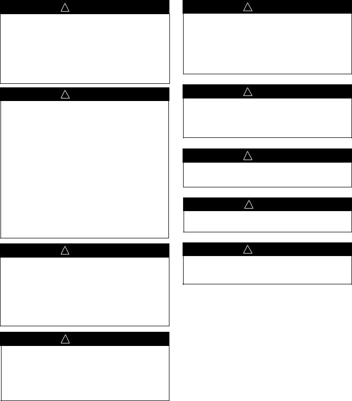
2.1 Unit Dimensions and Weight
Table 2.1
Unit Dimensions and Weight
Models |
H x D x W (in) |
Weight* (lb) |
|
|
|
4TTX6018J |
37 x 30 x 33 |
172 |
|
|
|
4TTX6024J |
37 x 30 x 33 |
173 |
4TTX6030J |
44 x 30 x 33 |
195 |
|
|
|
4TTX6036J |
46 x 34 x 37 |
221 |
|
|
|
4TTX6042J |
54 x 34 x 37 |
277 |
4TTX6048J |
54 x 34 x 37 |
281 |
|
|
|
4TTX6049H |
54 x 34 x 37 |
281 |
|
|
|
4TTX6060J |
54 x 34 x 37 |
286 |
4TTX6061J |
54 x 34 x 37 |
301 |
* Weight values are estimated.
When mounting the outdoor unit on a roof, be sure the roof will support the unit’s weight.
Properly selected isolation is recommended to alleviate sound or vibration transmission to the building structure.
Please refer to application bulletin for detailed mounting information.
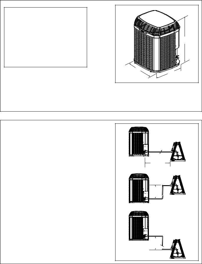
2.2Refrigerant Piping Limits
1.The maximum TOTAL length of refrigerant lines from outdoor to indoor unit should NOT exceed 150 feet (including lift).
2.The maximum vertical change should not exceed 50 feet.
3.Service valve connection diameters are shown in Table 5.1.
Note: For other line lengths, Refer to Refrigerant Piping Application Guide, SS-APG006-EN or Refrigerant Piping Software Program, 32- 3312-03 (or latest revision).
|
H |
W |
D |
|
Standard
Line Set
150’ Max
TOTAL Line Length
50’ Max Vertical Change 
50’ Max Vertical Change 
18-AC100D1-3-EN |
3 |
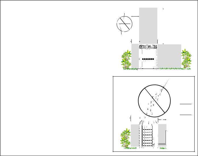
2.3 Suggested Locations for Best Reliability
Ensure the top discharge area is unrestricted for at least five (5) feet above the unit.
Three (3) feet clearance must be provided in front of the control box (access panels) and any other side requiring service.
Do not locate close to bedrooms as operational sounds may be objectionable.
Position the outdoor unit a minimum of 12” from any wall or surrounding shrubbery to ensure adequate airflow.
Outdoor unit location must be far enough away from any structure to prevent excess roof runoff water from pouring directly on the unit.
Avoid Install
Near Bedrooms
Min 5’ Unrestricted
Min 3’
Min. 12” to  Unrestricted
Shrubbery

 Access Panel
Min. 12” to |
Min. 12” |
Shrubbery |
|
|
to Wall |
2.4 Coastal Considerations
If installed within one mile of salt water, including seacoasts and inland waterways, models without factory supplied Seacoast Salt Shields require the addition of BAYSEAC001 (Seacoast Kit) at installation time.
4 |
18-AC100D1-3-EN |

Section 3. Unit Preparation
3.1 Prepare The Unit For Installation
STEP 1 - Check for damage and report promptly to the carrier any damage found to the unit.
STEP 2 - To remove the unit from the pallet, remove tabs by cutting with a sharp tool.
Section 4. Setting the Unit
4.1 Pad Installation
When installing the unit on a support pad, such as a concrete slab, consider the following:
•The pad should be at least 1” larger than the unit on all sides.
•The pad must be separate from any structure.
•The pad must be level.
•The pad should be high enough above grade to allow for drainage.
•The pad location must comply with National, State, and Local codes.
18-AC100D1-3-EN |
5 |
Section 5. Refrigerant Line Considerations
5.1 Refrigerant Line and Service Valve Connection Sizes
Table 5.1
|
Line Sizes |
Service Valve Connection Sizes |
|||
|
|
|
|
|
|
Model |
Vapor |
Liquid |
Vapor Line |
Liquid Line |
|
Line |
Line |
Connection |
Connection |
||
|
|||||
|
|
|
|
|
|
4TTX6018J |
3/4 |
3/8 |
3/4 |
3/8 |
|
|
|
|
|
|
|
4TTX6024J |
3/4 |
3/8 |
3/4 |
3/8 |
|
|
|
|
|
|
|
4TTX6030J |
3/4 |
3/8 |
3/4 |
3/8 |
|
|
|
|
|
|
|
4TTX6036J |
7/8 |
3/8 |
3/4 |
3/8 |
|
|
|
|
|
|
|
4TTX6042J |
7/8 |
3/8 |
7/8 |
3/8 |
|
|
|
|
|
|
|
4TTX6048J |
7/8 |
3/8 |
7/8 |
3/8 |
|
|
|
|
|
|
|
4TTX6049J |
7/8 |
3/8 |
7/8 |
3/8 |
|
|
|
|
|
|
|
4TTX6060J |
1-1/8 |
3/8 |
7/8 |
3/8 |
|
|
|
|
|
|
|
4TTX6061J |
1-1/8 |
3/8 |
7/8 |
3/8 |
|
|
|
|
|
|
|
5.2 Factory Charge
Trane outdoor condensing units are factory charged with the system charge required for the outdoor condensing unit, fifteen (15) feet of tested connecting line, and the smallest indoor evaporative coil match. If connecting line length exceeds fifteen (15) feet and/or a larger indoor evaporative coil is installed, then final refrigerant charge adjustment is necessary.
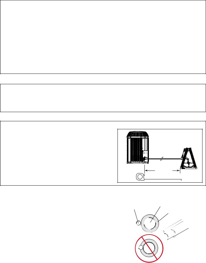
5.3 Required Refrigerant Line Length
Determine required line length and lift. You will need this later in STEP 2 of Section 14.
Total Line Length = __________ Ft.
Total Vertical Change (lift) = __________ Ft.
Line Length |
5.4 Refrigerant Line Insulation
Important: The Vapor Line must always be |
|
|
|
|
Vapor Line |
|
|
insulated. DO NOT allow the Liquid Line and |
Liquid Line |
|
|
Vapor Line to come in direct (metal to metal) |
|
|
|
|
Insulation |
|
|
contact. |
|
|
|
|
|
|
|
|
|
|
|
|
|
|
|
6 |
18-AC100D1-3-EN |
5.5 Reuse Existing Refrigerant Lines
▲! CAUTION
If using existing refrigerant lines make certain that all joints are brazed, not soldered.
For retrofit applications, where the existing indoor evaporator coil and/or refrigerant lines will be used, the following precautions should be taken:
• Ensure that the indoor evaporator coil and refrigerant lines are the correct size.
•Ensure that the refrigerant lines are free of leaks, acid, and oil.
Section 6. Refrigerant Line Routing
6.1 Precautions
Important: Take precautions to prevent noise |
Comply with National, State, and Local Codes when |
within the building structure due to vibration |
isolating line sets from joists, rafters, walls, or other |
transmission from the refrigerant lines. |
structural elements. |
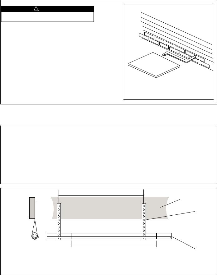
For Example:
•When the refrigerant lines have to be fastened to floor joists or other framing in a structure, use isolation type hangers.
•Isolation hangers should also be used when refrigerant lines are run in stud spaces or enclosed ceilings.
•Where the refrigerant lines run through a wall or sill, they should be insulated and isolated.
•Isolate the lines from all ductwork.
•Minimize the number of 90º turns.
8 Feet Maximum
Side View
8 Feet Maximum
Secure Vapor line from joists using isolators every 8 ft. Secure Liquid Line directly to Vapor line using tape, wire, or other appropriate method every 8 ft.
Isolation From Joist/Rafter
Joist/Rafter
Isolator
Line Set
18-AC100D1-3-EN |
7 |
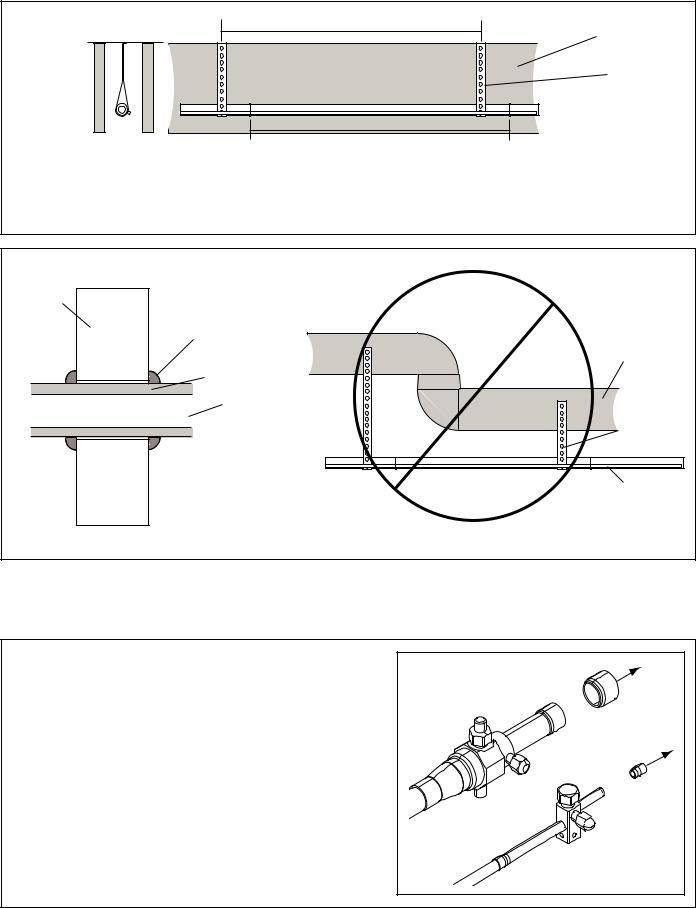
8 Feet Maximum
Wall
Isolator
 Line Set
Side View |
8 Feet Maximum |
Secure Vapor Line using isolators every 8 ft. Secure Liquid Line directly to Vapor Line using tape, wire, or other appropriate method every 8 ft.
Isolation In Wall Spaces
Wall |
|
|
Sealant |
|
Ductwork |
|
Insulation |
|
Vapor Line |
|
Isolator |
|
Line Set |
Isolation Through Wall |
DO NOT hang line sets from ductwork |
Section 7. Refrigerant Line Brazing
7.1 Braze The Refrigerant Lines
|
STEP 1 - Remove caps or plugs. Use a debur- |
|
ing tool to debur the pipe ends. Clean both |
|
internal and external surfaces of the tubing |
|
using an emery cloth. |
8 |
18-AC100D1-3-EN |
 Loading...