


 Loading...
Installation, Operation,
and Maintenance
Gas Unit Heater
Tubular Gas-Fired Direct Spark Propeller Unit Heater
 SAFETY WARNING
Only qualified personnel should install and service the equipment. The installation, starting up, and servicing of heating, ventilating, and air-conditioning equipment can be hazardous and requires specific knowledge and training. Improperly installed, adjusted or altered equipment by an unqualified person could result in death or serious injury. When working on the equipment, observe all precautions in the literature and on the tags, stickers, and labels that are attached to the equipment.
March 2012 |
GTND-SVX01B-EN |
Warnings, Cautions and Notices
Warnings, Cautions and Notices. Note that warnings, cautions and notices appear at appropriate intervals throughout this manual. Warnings are provide to alert installing contractors to potential hazards that could result in death or personal injury. Cautions are designed to alert personnel to hazardous situations that could result in personal injury, while notices indicate a situation that could result in equipment or property-damage-only accidents.
Your personal safety and the proper operation of this machine depend upon the strict observance of these precautions.
Read this manual thoroughly before operating or servicing this unit.
ATTENTION: Warnings, Cautions and Notices appear at appropriate sections throughout this literature. Read these carefully:
 WARNING
 CAUTIONs
NOTICE:
Indicates a potentially hazardous situation which, if not avoided, could result in death or serious injury.
Indicates a potentially hazardous situation which, if not avoided, could result in minor or moderate injury. It could also be used to alert against unsafe practices.
Indicates a situation that could result in equipment or property-damage only
Important
Environmental Concerns!
Scientific research has shown that certain man-made chemicals can affect the earth’s naturally occurring stratospheric ozone layer when released to the atmosphere. In particular, several of the identified chemicals that may affect the ozone layer are refrigerants that contain Chlorine, Fluorine and Carbon (CFCs) and those containing Hydrogen, Chlorine, Fluorine and Carbon (HCFCs). Not all refrigerants containing these compounds have the same potential impact to the environment. Trane advocates the responsible handling of all refrigerants-including industry replacements for CFCs such as HCFCs and HFCs.
Responsible Refrigerant Practices!
Trane believes that responsible refrigerant practices are important to the environment, our customers, and the air conditioning industry. All technicians who handle refrigerants must be certified. The Federal Clean Air Act (Section 608) sets forth the requirements for handling, reclaiming, recovering and recycling of certain refrigerants and the equipment that is used in these service procedures. In addition, some states or municipalities may have additional requirements that
must also be adhered to for responsible management of refrigerants. Know the applicable laws and follow them.
 WARNING
Proper Field Wiring and Grounding
Required!
All field wiring MUST be performed by qualified personnel. Improperly installed and grounded field wiring poses FIRE and ELECTROCUTION hazards. To avoid these hazards, you MUST follow requirements for field wiring installation and grounding as described in NEC and your local/state electrical codes. Failure to follow code could result in death or serious injury.
 WARNING
Personal Protective Equipment (PPE)
Required!
Installing/servicing this unit could result in exposure to electrical, mechanical and chemical hazards.
•Before installing/servicing this unit, technicians MUST put on all Personal Protective Equipment (PPE) recommended for the work being undertaken. ALWAYS refer to appropriate MSDS sheets and OSHA guidelines for proper PPE.
•When working with or around hazardous chemicals, ALWAYS refer to the appropriate MSDS sheets and OSHA guidelines for information on allowable personal exposure levels, proper respiratory protection and handling recommendations.
•If there is a risk of arc or flash, technicians MUST put on all Personal Protective Equipment (PPE) in accordance with NFPA 70E or other country-specific requirements for arc flash protection, PRIOR to servicing the unit.
Failure to follow recommendations could result in death or serious injury.
ATTENTION: READ THIS MANUAL AND ALL LABELS ATTACHED TO THE UNIT CAREFULLY BEFORE ATTEMPTING TO INSTALL, OPERATE OR SERVICE THESE UNITS! CHECK UNIT DATA PLATE FOR TYPE OF GAS AND ELECTRICAL SPECIFICATIONS AND MAKE CERTAIN THAT THESE AGREE WITH THOSE AT POINT OF INSTALLATION. RECORD THE UNIT MODEL AND SERIAL No.(s) IN THE SPACE PROVIDED. RETAIN FOR FUTURE REFERENCE.
© 2012 Trane All rights reserved |
GTND-SVX01B-EN |
Warnings, Cautions and Notices
 WARNING
Hazardous Service Procedures!
The maintenance and troubleshooting procedures recommended in this manual could result in exposure to electrical, mechanical or other potential safety hazards. Always refer to the safety warnings provided throughout this manual concerning these procedures. When possible, disconnect all electrical power including remote disconnect and discharge all energy storing devices such as capacitors before servicing. Follow proper lockout/tagout procedures to ensure the power can not be inadvertently energized. When necessary to work with live electrical components, have a qualified licensed electrician or other individual who has been trained in handling live electrical components perform these tasks. Failure to follow all of the recommended safety warnings provided, could result in death or serious injury.
 WARNING
Overheating or Flooding Could Cause Fire or Explosion!
Overheating or flooding (where any part of the unit heater has been under water) could result in fire or explosion. Should overheating occur, or the gas supply fails to shut off, shut off the manual gas valve to the unit heater before shutting off the electrical supply. Do not use the unit heater if any part has been under water. Immediately call a qualified service technician to inspect the unit heater and replace any gas control which has been underwater. Failure to follow these recommendations could result in death or serious injury.
 WARNING
Hazardous Gases and Flammable
Vapors!
Exposure to hazardous gases from fuel substances have been shown to cause cancer, birth defects or other reproductive harm. Improper installation, adjustment, alteration, service or use of this product could cause flammable mixtures. To avoid hazardous gases and flammable vapors follow proper installation and set up of this product and all warnings as provided in this manual. Failure to follow all instructions could result in death or serious injury.
Trademarks
Trane and the Trane logo are trademarks of Trane in the United States and other countries.
GTND-SVX01B-EN |
3 |
Introduction
 WARNING
Safety Alert!
You MUST follow all recommendations below. Failure to do so could result in death or serious injury.
For Your Safety
The use and storage of gasoline or other flammable vapors and liquids in open containers in the vicinity of this appliance is hazardous.
If you smell gas:
1.Do not try to light any appliance.
2.Do not touch electrical switches; do not use any phone in your building.
3.Immediately call your gas supplier from a neighbor’s phone. Follow the gas supplier’s instructions.
4.If you cannot reach your gas supplier, call your fire department.
Approved For Use in California
 WARNING
Toxic Hazard!
Install, operate and maintain unit in accordance with manufacturer’s instructions to avoid exposure to fuel substances or substances from incomplete combustion which could result in death or serious illness. The state of California has determined that these substances may cause cancer, birth defects, or other reproductive harm.
Installer’s Responsibility
Installer Please Note: This equipment has been test fired and inspected. It has been shipped free from defects from our factory. However, during shipment and installation, problems such as loose wires, leaks, or loose fasteners may occur. It is the installer’s responsibility to inspect and correct any problems that may be found.
Receiving Instructions
Inspect shipment immediately when received to determine if any damage has occurred to the unit during shipment. After the unit has been uncrated, check for any visible damage to the unit. If any damage is found, the consignee should sign the bill of lading indicating such damage and immediately file claim for damage with the transportation company.
Important: It is the equipment owner’s responsibility to provide any scaffolding or other apparatus required to perform emergency service or annual/periodic maintenance to this equipment.
4 |
GTND-SVX01B-EN |

Table of Contents |
|
Warnings, Cautions and Notices . . . . . . . . . |
. 2 |
Model Number Descriptions . . . . . . . . . . . . . . |
6 |
Indoor Gas Heating Units . . . . . . . . . . . . . . . |
6 |
General Information . . . . . . . . . . . . . . . . . . . . . |
7 |
Description . . . . . . . . . . . . . . . . . . . . . . . . . . . |
7 |
General Safety Information . . . . . . . . . . . . . |
7 |
Identification of Parts . . . . . . . . . . . . . . . . . . |
8 |
Unit Dimensions and Weights . . . . . . . . . . . |
12 |
Installation: Mechanical . . . . . . . . . . . . . . . . . |
16 |
Air Distribution . . . . . . . . . . . . . . . . . . . . . |
16 |
Clearances . . . . . . . . . . . . . . . . . . . . . . . . . |
17 |
Nozzle Assembly . . . . . . . . . . . . . . . . . . . |
19 |
Installation: Piping . . . . . . . . . . . . . . . . . . . . . . |
21 |
Gas Supply Piping . . . . . . . . . . . . . . . . . . . . |
21 |
Pipe Sizing . . . . . . . . . . . . . . . . . . . . . . . . |
21 |
Pipe Installation . . . . . . . . . . . . . . . . . . . . . . |
22 |
Installation: Venting . . . . . . . . . . . . . . . . . . . |
23 |
Standard Combustion . . . . . . . . . . . . . . . |
25 |
All Unit Sizes: Vertically Vented Unit Heaters |
|
(Category I) . . . . . . . . . . . . . . . . . . . . . . . . |
25 |
All Unit Sizes: Horizontally Vented Unit Heat- |
|
ers (Category III) . . . . . . . . . . . . . . . . . . . . |
26 |
Unit Sizes 30–120 Only: Vertically Vented Unit |
|
Heaters (Category III) . . . . . . . . . . . . . . . . |
28 |
Separated Combustion . . . . . . . . . . . . . . |
32 |
Unit Sizes 30–120 Only: Category III . . . . |
32 |
Installation: Electrical . . . . . . . . . . . . . . . . . . . |
37 |
Electrical Connections . . . . . . . . . . . . . . . . . |
37 |
Thermostat Wiring and Location . . . . . . |
37 |
Start-Up . . . . . . . . . . . . . . . . . . . . . . . . . . . . . . . |
39 |
All Unit Sizes: Operation . . . . . . . . . . . . . . . |
39 |
Power Vented Propeller Units—Direct Spark |
|
Ignition . . . . . . . . . . . . . . . . . . . . . . . . . . . |
39 |
Gas Equipment Start-Up . . . . . . . . . . . . . . . |
43 |
Maintenance . . . . . . . . . . . . . . . . . . . . . . . . . . . |
44 |
Periodic Service . . . . . . . . . . . . . . . . . . . . |
44 |
How to Order Replacement Parts . . . . . . |
45 |
Diagnostics . . . . . . . . . . . . . . . . . . . . . . . . . . . . . |
46 |
Troubleshooting . . . . . . . . . . . . . . . . . . . . . . . |
46 |
Wiring Diagrams . . . . . . . . . . . . . . . . . . . . . . . . |
50 |
GTND-SVX01B-EN |
5 |

Model Number Descriptions
Indoor Gas Heating
Units
Note: All units are AGA approved. For CGA approved units, contact Air Handling Product Support.
Digit 1 — Gas Heating
Equipment
G = Gas Heating Equipment
Digit 2 — Product Type
T= Tubular Heat Exchanger - Propeller Type
Digit 3 — Fuel
N |
= |
Natural Gas |
P |
= |
LP Gas (Propane) |
Digit 4 — Development
Sequence
D = Fourth Generation
Digits 5, 6, 7 — Input Capacity
Single Furnace
003 |
= |
30 MBh |
015 |
= |
150 MBh |
004 |
= |
45 MBh |
017 |
= |
175 MBh |
006 |
= |
60 MBh |
020 |
= |
200 MBh |
007 |
= |
75 MBh |
022 |
= |
225 MBh |
009 |
= |
90 MBh |
025 |
= |
250 MBh |
011 |
= |
105 MBh |
030 |
= |
300 MBh |
120 = |
120 MBh |
035 |
= |
350 MBh |
|
|
|
|
040 |
= |
400 MBh |
Digit 8 — Main Power Supply
A |
= |
115/60/1 |
D |
= |
230/60/3 |
B |
= |
230/60/1 |
E |
= |
460/60/3 |
C |
= |
208/60/3 |
F |
= |
575/60/3 |
Digit 9 — Gas Control Option
D= Single-Stage, Intermittent Pilot Ignition
E= Two-Stage, Intermittent Pilot Ignition
H |
= |
Electronic Modulating with |
|
|
Room |
|
|
T-Stat, Intermittent Pilot Ignition |
J |
= |
Electronic Modulating with |
|
|
Duct-Stat, Intermittent Pilot |
|
|
Ignition |
L= Electronic Modulating with External 4–20 mA Input
N = Electronic Modulating with External 0–10 Vdc Input
T= Single Stage Direct Spark Ignition
V = Two-Stage, Direct Spark Ignition
Digit 10 — Design Sequence
G = Seventh Design
Digit 11 — Heat Exchanger
Material
1= Aluminized Steel
2= #409 Stainless Steel
3= #321 Stainless Steel
Digit 12 — Rooftop
Arrangements
0 = None (Indoor Unit)
Digit 13 — Rooftop Heating Unit
Motor Selection
0= None (Indoor Unit and Rooftop Duct Furnace)
Digit 14 — Rooftop Fan Section
0= None (Indoor Unit and Rooftop Duct Furnace)
Digit 15 — Miscellaneous
Options
0 = None
B= Orifices For Elevation Above 2000 Feet (Specify Elevation)
J |
= |
Totally Enclosed Motor |
7 |
= |
OSHA Fan Guard |
6 |
GTND-SVX01B-EN |
General Information
Description
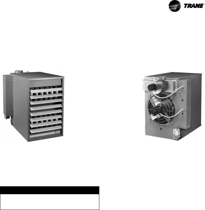
The Tubular Gas-Fired Unit Heater is a factory assembled, power vented, low static pressure type propeller fan unit heater designed to be suspended within the space to be heated. THESE HEATERS ARE NOT TO BE CONNECTED TO
Figure 1. Tubular Propeller Unit Heaters
DUCTWORK. The designs are certified by ETL as providing a minimum of 80 percent thermal efficiency, and approved for use in California. Do not alter these units in any way. If you have any questions after reading this manual, contact the manufacturer.
Front view (Unit size 150) |
Rear view (Unit size 150) |
|
See “Identification of Parts,” p. 8 for unit components. |
General Safety Information
Important: This product must be installed by a licensed plumber or gas fitter when installed within the Commonwealth of Massachusetts.
 WARNING
Safety Alert!
You MUST follow all recommendations below. Failure to do so could result in death or serious injury.
•Installation must be made in accordance with local codes, or in absence of local codes with the latest edition of ANSI Standard Z223.1 (N.F.P.A. No. 54) National Fuel Gas Code.
All of the ANSI and NFPA Standards referred to in these installation instructions are those that were applicable at the time the design of this appliance was certified. The ANSI Standards are available from the CSA Information Services, 1-800-463-6727. The NFPA Standards are available from the National Fire Protection Association, Batterymarch Park, Quincy, MA 02269.
Unit sizes 150–400: These units are designed for use in airplane hangars when installed in
accordance with ANSI/NFPA No. 409, and in public garages when installed in accordance with NFPA No. 88A and NFPA No. 88B.
Unit sizes 30–120: If installed in Canada, the installation must conform with local building codes, or in absence of local building codes, with CAN/CanGa-B149.1 “Installation Codes for Natural Gas Burning Appliances and Equipment” or CAN/CanGa-B149.2 “Installation Codes for Propane Gas Burning Appliances and Equipment”. These unit heaters have been designed and certified to comply with CSA 2.6.
Unit sizes 150–400: If installed in Canada, the installation must conform with local building codes, or in absence of local building codes, with CSA-B149.1 “Installation Codes for Natural Gas Burning Appliances and Equipment” or CSA-B149.2 “Installation Codes for Propane Gas Burning Appliances and Equipment”. These unit heaters have been designed and certified to comply with CSA 2.6. Also see sections on installation in “Aircraft Hangers,” p. 16 and “Public Garages,” p. 16.
•Do not alter the unit heater in any way or damage to the unit and/or severe personal injury or death could occur!
GTND-SVX01B-EN |
7 |
General Information
•Turn off the gas supply and disconnect all electric power, including remote disconnects before servicing unit. Follow proper lockout/ tagout procedures to ensure the power can not be inadvertently energized and the gas can not be inadvertently turned on. Failure to turn off gas or disconnect power before servicing could result in death or serious injury.
•Follow installation instructions CAREFULLY to avoid creating unsafe conditions. All wiring should be done and checked by a qualified electrician, using copper wire only.
•All gas connections should be made and leaktested by a suitably qualified individual, per instructions in this manual. Also follow procedures listed in “Gas Equipment Start-Up,” p. 43.
•Use only the fuel for which the unit heater is designed (see rating plate). Using LP gas in a heater that requires natural gas, or vice versa, will create the risk of gas leaks, carbon monoxide poisoning and explosion.
Important: Do not attempt to convert the heater for use with a fuel other than the one intended. Such conversion is dangerous, as it could create the risks listed previously.
•Make certain that the power source conforms to the electrical requirements of the heater.
•All field-installed wiring must be completed by qualified personnel. All field-installed wiring must comply with NEC and applicable local codes. Failure to follow this instruction could result in death or serious injuries.
•Special attention must be given to any grounding information pertaining to this heater. To prevent the risk of electrocution, the heater must be securely and adequately grounded. This should be accomplished by connecting a grounded conductor between the service panel and the heater. To ensure a proper ground, the grounding means must be tested by a qualified electrician.
•Do not insert fingers or foreign objects into the heater or its air moving device. Do not block or tamper with the heater in any manner while in operation or just after it has been turned off, as some parts may be hot enough to cause injury.
•This heater is intended for general heating applications ONLY. It must NOT be used in potentially dangerous locations such as flammable, explosive, chemical-laden or wet atmospheres.
•Do not attach ductwork to this product or use it as a makeup air heater. Such usage voids the warranty and will create unsafe operation.
•In cases in which property damage may result from malfunction of the heater, a backup system or a temperature sensitive alarm should be used.
•Should overheating occur, or the gas supply fail to shut off, shut off the manual gas valve to the heater before shutting off the electrical supply.
•The open end of piping systems being purged must not discharge into areas where there are sources of ignition or into confined spaces UNLESS precautions are taken as follows: 1) by ventilation of the space, 2) control of purging rate, 3) elimination of all hazardous conditions. All precautions must be taken to perform this operation in a safe manner.
•When connecting to existing gas lines be sure to valve off the gas supply ahead of connection point. To avoid explosion or possible fire, always purge all residual gas from piping before cutting into existing line or removing threaded fittings. Failure to remove all gas vapors could result in death or serious injury or equipment or property- only-damage.
Unless otherwise specified, the following conversions may be used for calculating SI unit measurements:
1 foot = 0.305 m |
1 inch water column = 0.249 kPa |
1 inch = 25.4 mm |
1 meter/second = FPM ÷ 196.8 |
1 psig = 6.894 kPa |
1 liter/second = CFM x 0.472 |
1 pound = 0.453 kg |
1000 Btu per hour = 0.293 kW |
1 gallon = 3.785 L |
1000 Btu/Cu. Ft. = 37.5 MJ/m3 |
|
1 cubic foot = 0.028 m3 |
Identification of Parts
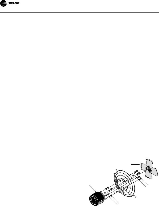
Figure 2. All unit sizes: Propeller parts
Fan Blade
Fan Guard 
Motor
Hardware
Hardware |
D4430 |
Note: With unit sizes 30 and 45, no rubber grommets are supplied.
8 |
GTND-SVX01B-EN |
General Information
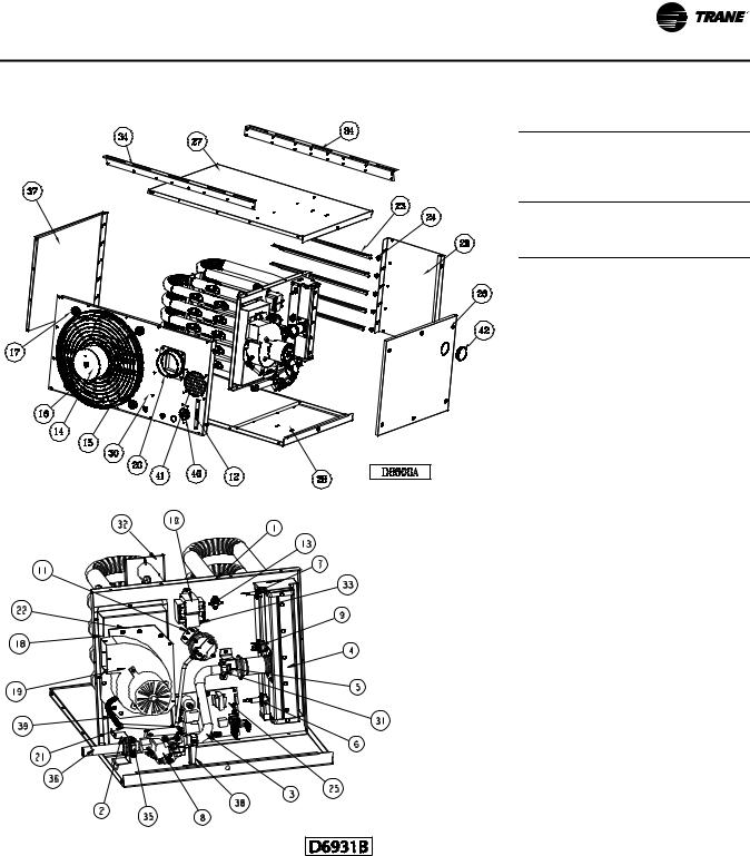
Figure 3. Unit sizes 30–120: Unit parts
# |
Description |
1. |
Vestible Panel/Tube Assembly |
|
(Heat Exchanger) |
2. |
Bracket/Gas Train |
|
|
3. |
Manifold |
|
|
4. |
Burner Assembly |
5. |
Standard Orifice (a) |
|
Natural Gas or Propane (LP) Gas |
6. |
Spark Ignitor |
|
|
7. |
Flame Sensor |
8. |
Gas Valve |
|
Natural or Propane (LP) Gas |
9. |
Manual Rollout Safety Switch |
|
|
10. |
Transformer, 50 VA, 115/24 |
|
|
11. |
Air Pressure Switch |
|
|
12. |
Terminal Block Plate |
|
|
13. |
High Limit Switch |
|
|
14. |
Fan Motor |
|
|
15. |
OSHA Fan Guard |
|
|
16. |
Standard Fan |
|
|
17. |
Fan/Guard/Motor Mount Hardware Kit |
|
|
18. |
Flue Collector(b) |
19. |
Power Venter (Drafter) Assembly |
|
|
20. |
Flue Collar Assembly |
|
|
21. |
Vinyl Tubing (Pressure Switch) |
|
|
22. |
Power Venter Mounting Plate |
|
|
23. |
Louver |
|
|
24. |
Louver Spring |
|
|
25. |
Control Board |
|
|
26. |
Access Panel |
|
|
27. |
Top Jacket Panel w/Insulation |
|
|
28. |
Bottom Jacket Panel w/Insulation |
|
|
29. |
Front Jacket Panel |
|
|
30. |
Rear Jacket Panel |
|
|
31. |
Bracket, Manifold |
|
|
32. |
Tube Support Bracket |
|
|
33. |
Green Ground Screw |
|
|
34. |
Hanger Bracket |
|
|
35. |
Manifold Clamp |
|
|
36. |
Pipe Nipple |
|
|
37. |
Left Side Panel |
|
|
38. |
Manifold Support Bracket Kit |
|
|
39. |
Spring |
|
|
40. |
Grommet |
|
|
41. |
Inlet Screen Assembly |
|
|
42. |
Burner Box View Port |
|
|
|
|
(a)The orifice shown are for units operating at normal altitudes of 0 to 2000 ft (610 m).
(b)When replacing a flue collector, make sure that the flue collector box is sealed completely with factory supplied gasket.
GTND-SVX01B-EN |
9 |
General Information
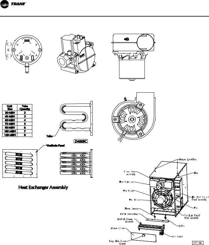
Figure 4. Unit sizes 30–120: Component parts |
Figure 6. Unit sizes 30–120: Power venter assembly |
|||||||||||||||||||||||||||||||||||||||
|
|
|
|
|
|
|
|
|
|
|
|
|
|
|
|
|
|
|
|
|
|
|
|
|
|
|
|
|
|
|
|
|
|
|
|
|
|
|
|
|
|
|
|
|
|
|
|
|
|
|
|
|
|
|
|
|
|
|
|
|
|
|
|
|
|
|
|
|
|
|
|
|
|
|
|
|
|
|
|
|
|
|
|
|
|
|
|
|
|
|
|
|
|
|
|
|
|
|
|
|
|
|
|
|
|
|
|
|
|
|
|
|
|
|
|
|
|
|
|
|
|
|
|
|
|
|
|
|
|
|
|
|
|
|
|
|
|
|
|
|
|
|
|
|
|
|
|
|
|
|
|
|
|
|
|
|
|
|
|
|
|
|
|
|
|
|
|
|
|
|
|
|
|
|
|
|
|
|
|
|
|
|
|
|
|
|
|
|
|
|
|
|
|
|
|
|
|
|
|
|
|
|
|
|
|
|
|
|
|
|
|
|
|
|
|
|
|
|
|
|
|
|
|
|
|
|
|
|
|
|
|
|
|
|
|
|
|
|
|
|
|
|
|
|
|
|
D03 |
Pressure switch |
Gas valve |
Figure 5. Unit sizes 30–120: Internal furnace components
Figure 7. Unit sizes 150–400: Component parts
10 |
GTND-SVX01B-EN |

|
|
|
|
|
|
|
|
|
|
|
|
|
|
|
|
|
|
|
|
|
General Information |
|||||||||||||||||||||||
Figure 8. Unit sizes 150–400: Heat exchanger |
Figure 10. Unit sizes 150–250: Power venter assembly |
|||||||||||||||||||||||||||||||||||||||||||
assembly |
|
|
|
|
|
|
|
|
|
|
|
|
|
|
|
|
|
|
|
|
|
|
|
|
|
|
|
|
|
|
|
|
|
|
|
|
|
|
|
|
|
|
|
|
|
|
|
|
|
|
|
|
|
|
|
|
|
|
|
|
|
|
|
|
|
|
|
|
|
|
|
|
|
|
|
|
|
|
|
|
|
|
|
|
|
|
|
|
|
|
|
|
|
|
|
|
|
|
|
|
|
|
|
|
|
|
|
|
|
|
|
|
|
|
|
|
|
|
|
|
|
|
|
|
|
|
|
|
|
|
|
|
|
|
|
|
|
|
|
|
|
|
|
|
|
|
|
|
|
|
|
|
|
|
|
|
|
|
|
|
|
|
|
|
|
|
|
|
|
|
|
|
|
|
|
|
|
|
|
|
|
|
|
|
|
|
|
|
|
|
|
|
|
|
|
|
|
|
|
|
|
|
|
|
|
|
|
|
|
|
|
|
|
|
|
|
|
|
|
|
|
|
|
|
|
|
|
|
|
|
|
|
|
|
|
|
|
|
|
|
|
|
|
|
|
|
|
|
|
|
|
|
|
|
|
|
|
|
|
|
|
|
|
|
|
|
|
|
|
|
|
|
|
|
|
|
|
|
|
|
|
|
|
|
|
|
|
|
|
|
|
|
|
|
|
|
|
|
|
|
|
|
|
|
|
|
|
|
|
|
|
|
|
|
|
|
|
|
|
|
|
|
|
|
|
|
|
|
|
|
|
|
|
|
|
|
|
|
|
|
|
|
|
|
|
|
|
|
|
|
|
|
|
|
|
|
|
|
|
|
|
|
|
|
|
|
|
|
|
|
|
|
|
|
|
|
|
|
|
|
|
|
|
|
|
|
|
|
|
|
|
|
|
|
|
|
|
|
|
|
|
|
|
|
|
|
|
|
|
|
|
|
|
|
|
|
|
|
|
|
|
|
|
|
|
|
|
|
|
|
|
|
|
|
|
|
|
|
|
|
|
|
|
|
|
|
|
|
|
|
|
|
|
|
|
|
|
|
|
|
|
|
|
|
|
|
|
|
|
|
|
|
|
|
|
|
|
|
|
|
|
|
|
|
|
|
|
|
|
|
|
|
|
|
|
|
|
|
|
|
|
|
|
|
|
|
|
|
|
|
|
|
|
|
|
|
|
|
|
|
|
|
|
|
|
|
|
|
|
|
|
|
|
|
|
|
|
|
|
|
|
|
|
|
|
|
|
|
|
|
|
|
|
|
|
|
|
|
|
|
|
|
|
|
|
|
|
|
|
|
|
|
|
|
|
|
|
|
|
|
|
|
|
|
Figure 11. Unit sizes 300–400: Power venter assembly
Figure 9. Unit sizes 150–400: Electrical control panel
Figure 12. Unit sizes 150–400: Turbulator/High limit location
GTND-SVX01B-EN |
11 |

Unit Dimensions and Weights
Table 1. |
Unit sizes 30–120: Performance and specification data |
|
|
|
|
|
|||
|
|
|
|
|
|
|
|
|
|
Unit Size |
|
|
30 |
45 |
60 |
75 |
90 |
105 |
120 |
PERFORMANCE DATA(a) |
|
|
|
|
|
|
|
|
|
Input |
|
Btu/h |
30,000 |
45,000 |
60,000 |
75,000 |
90,000 |
105,000 |
120,000 |
|
|
(kW) |
(8.8) |
(13.2) |
(17.6) |
(22.0) |
(26.4) |
(30.8) |
(35.2) |
Output |
|
Btu/h |
24,900 |
37,350 |
49,800 |
61,500 |
73,800 |
86,100 |
98,400 |
|
|
(kW) |
(7.2) |
(10.9) |
(14.5) |
(18.0) |
(21.6) |
(25.2) |
(28.8) |
|
|
|
|
|
|
|
|
|
|
Thermal Efficiency |
% |
83 |
83 |
83 |
82 |
82 |
82 |
82 |
|
Free Air Delivery CFM |
cfm |
370 |
550 |
740 |
920 |
1,100 |
1,300 |
1,475 |
|
|
|
(m3/s) |
(0.175) |
(0.260) |
(0.349) |
(0.434) |
(0.519) |
(0.614) |
(0.696) |
Air Temperature Rise |
°F |
60 |
60 |
60 |
60 |
60 |
60 |
60 |
|
|
|
(°C) |
(15) |
(15) |
(15) |
(15) |
(15) |
(15) |
(15) |
|
|
|
|
|
|
|
|
|
|
Full Load Amps at 115V |
|
3.0 |
3.0 |
4.1 |
4.1 |
6.4 |
6.4 |
6.4 |
|
Maximum Circuit Ampacity |
|
3.5 |
3.5 |
4.8 |
4.8 |
7.5 |
7.5 |
7.5 |
|
|
|
|
|
|
|
|
|
|
|
MOTOR DATA: |
|
|
|
|
|
|
|
|
|
Motor |
|
hp |
1/20 |
1/20 |
1/12 |
1/12 |
1/10 |
1/10 |
1/10 |
|
|
(kW) |
(0.04) |
(0.04) |
(0.06) |
(0.06) |
(0.075) |
(0.075) |
(0.075) |
Type |
|
|
SP |
SP |
SP |
SP |
SP |
SP |
SP |
RPM |
|
|
1650 |
1650 |
1050 |
1050 |
1050 |
1050 |
1050 |
Amps @ 115V |
|
1.9 |
1.9 |
2.6 |
2.6 |
4.2 |
4.2 |
4.2 |
|
|
|
|
|
|
|
|
|
|
|
DIMENSIONAL DATA |
|
|
|
|
|
|
|
|
|
“A” Jacket Height |
in. |
12-3/8 |
12-3/8 |
15-7/8 |
15-7/8 |
22-5/8 |
22-5/8 |
22-5/8 |
|
|
|
(mm) |
(314) |
(314) |
(403) |
(403) |
(574) |
(574) |
(574) |
“B” Overall Height |
in. |
13-1/4 |
13-1/4 |
16-13/16 |
16-13/16 |
23-9/16 |
23-9/16 |
23-9/16 |
|
|
|
(mm) |
(337) |
(337) |
(427) |
(427) |
(598) |
(598) |
(598) |
“C” Overall Depth |
in. |
25-7/8 |
25-7/8 |
26-3/16 |
26-3/16 |
26-3/8 |
26-3/8 |
26-3/8 |
|
|
|
(mm) |
(632) |
(632) |
(665) |
(665) |
(670) |
(670) |
(670) |
“D1” Center Line Height of Flue(b) |
in. |
8-1/2 |
8-1/2 |
10-3/8 |
10-3/8 |
13-5/8 |
13-5/8 |
13-5/8 |
|
|
|
(mm) |
(216) |
(216) |
(263) |
(263) |
(346) |
(346) |
(346) |
“D2” Center Line Height of Air Intake |
in. |
8-1/2 |
8-1/2 |
8 |
8 |
8-5/8 |
8-5/8 |
8-5/8 |
|
|
|
(mm) |
(216) |
(216) |
(203) |
(203) |
(219) |
(219) |
(219) |
“E” Fan Diameter |
in. |
10 |
10 |
14 |
14 |
16 |
16 |
16 |
|
|
|
(mm) |
(254) |
(254) |
(356) |
(356) |
(406) |
(406) |
(406) |
|
|
|
|
|
|
|
|
|
|
“F” Discharge Opening Height |
in. |
10-13/16 |
10-13/16 |
14-7/16 |
14-7/16 |
21-3/16 |
21-3/16 |
21-3/16 |
|
|
|
(mm) |
(275) |
(275) |
(367) |
(367) |
(538) |
(538) |
(538) |
“G” Vent Connection Diameter |
in. |
4 |
4 |
4 |
4 |
4 |
4 |
4 |
|
|
|
(mm) |
(102) |
(102) |
(102) |
(102) |
(102) |
(102) |
(102) |
“H1” Center Line of Flue Connection From Side |
in. |
7-1/4 |
7-1/4 |
7-1/4 |
7-1/4 |
7-3/4 |
7-3/4 |
7-3/4 |
|
|
|
(mm) |
(184) |
(184) |
(184) |
(184) |
(197) |
(197) |
(197) |
“H2” Center Line of Air Intake From Side |
in. |
2-3/4 |
2-3/4 |
2-3/4 |
2-3/4 |
3-1/2 |
3-1/2 |
3-1/2 |
|
|
|
(mm) |
(70) |
(70) |
(70) |
(70) |
(89) |
(89) |
(89) |
|
|
|
|
|
|
|
|
|
|
Vent Size Requirements - Standard Combustion |
|
|
|
|
|
|
|
|
|
Category I Horizontal(c) |
in. |
4 |
4 |
4 |
5 |
5 |
5 |
5 |
|
|
|
(mm) |
(102) |
(102) |
(102) |
(127) |
(127) |
(127) |
(127) |
Category III Horizontal |
in. |
4 |
4 |
4 |
4 |
4 |
4 |
4 |
|
|
|
(mm) |
(102) |
(102) |
(102) |
(102) |
(102) |
(102) |
(102) |
Category I & III Vertical |
in. |
4 |
4 |
4 |
4 |
4 |
4 |
4 |
|
|
|
(mm) |
(102) |
(102) |
(102) |
(102) |
(102) |
(102) |
(102) |
Vent Size Requirements - Separated Combustion |
|
|
|
|
|
|
|
|
|
Exhaust Diameter** |
in. |
4 |
4 |
4 |
4 |
5 |
5 |
5 |
|
|
|
(mm) |
(102) |
(102) |
(102) |
(102) |
(127) |
(127) |
(127) |
Intake Air Diameter |
in. |
4 |
4 |
4 |
4 |
5 |
5 |
5 |
|
|
|
(mm) |
(102) |
(102) |
(102) |
(102) |
(127) |
(127) |
(127) |
|
|
|
|
|
|
|
|
|
|
Unit Weight |
|
lb |
60 |
65 |
80 |
85 |
95 |
105 |
110 |
|
|
(kg) |
(27) |
(29) |
(36) |
(39) |
(43) |
(48) |
(50) |
|
|
|
|
|
|
|
|
|
|
Shipping Weight |
lb |
70 |
75 |
90 |
95 |
110 |
115 |
120 |
|
|
|
(kg) |
(32) |
(34) |
(41) |
(43) |
(50) |
(52) |
(54) |
(a)Ratings shown are for unit installations at elevations between 0 and 2000 ft. (610 m). For unit installations in USA above 2000 ft. (610 m), the unit input must be derated 4% for each 1000 ft. (305 m) above sea level; refer to local codes, or in absence of local codes, refer to the latest edition of the National Gas Code, ANSI Standard Z223.1 (N.F.P.A. No. 54). Also refer to Table 10, p. 42.
For installations in Canada, any reference to deration at altitudes in excess of 2000 ft. (610 m) are to be ignored. At altitudes of 2000 to 4500 ft. (610 to 1372 m), the unit must be derated to 90% of the normal altitude rating, and be so marked in accordance with the ETL certification.
(b)For all installations, the flue collar is included with the unit and should be field-installed per the instructions included with the unit.
(c)4”–5” reducer supplied where required.
12 |
GTND-SVX01B-EN |
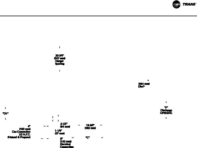
Unit Dimensions and Weights
Figure 13. Unit sizes 30–120: Dimensions, standard units
GTND-SVX01B-EN |
13 |
Unit Dimensions and Weights
Table 2. |
Unit sizes 150–400: Performance and specification data |
|
|
|
|
||||
|
|
|
|
|
|
|
|
|
|
Unit Size |
|
|
150 |
175 |
200 |
250 |
300 |
350 |
400 |
PERFORMANCE DATA(a) |
|
|
|
|
|
|
|
|
|
Input |
|
Btu/h |
150,000 |
175,000 |
200,000 |
250,000 |
300,000 |
350,000 |
400,000 |
|
|
(kW) |
(43.9) |
(51.2) |
(58.6) |
(73.2) |
(87.8) |
(102.5) |
(117.1) |
Output |
|
Btu/h |
124,500 |
145,250 |
166,000 |
207,500 |
249,000 |
290,500 |
332,000 |
|
|
(kW) |
(36.4) |
(42.5) |
(48.6) |
(60.7) |
(72.9) |
(85.1) |
(97.2) |
|
|
|
|
|
|
|
|
|
|
Thermal Efficiency |
% |
83 |
83 |
83 |
83 |
83 |
83 |
83 |
|
Free Air Delivery CFM |
cfm |
2,400 |
2,850 |
3,200 |
3,450 |
5,000 |
5,600 |
5,800 |
|
|
|
(m3/s) |
(1.133) |
(1.346) |
(1.511) |
(1.629) |
(2.361) |
(2.644) |
(2.738) |
Air Temperature Rise |
°F |
47 |
46 |
47 |
54 |
45 |
47 |
51 |
|
|
|
(°C) |
(26) |
(26) |
(26) |
(30) |
(24) |
(26) |
(28) |
|
|
|
|
|
|
|
|
|
|
Full Load Amps at 115V |
|
5.8 |
8.0 |
8.0 |
8.0 |
11.3 |
13.5 |
13.5 |
|
MOTOR DATA: |
|
|
|
|
|
|
|
|
|
Motor |
|
hp |
1/4 |
1/3 |
1/3 |
1/3 |
1/4 (2) |
1/3 (2) |
1/3 (2) |
|
|
(kW) |
(0.19) |
(0.25) |
(0.25) |
(0.25) |
(0.19) |
(0.25) |
(0.25) |
Type |
|
|
PSC |
PSC |
PSC |
PSC |
PSC |
PSC |
PSC |
RPM |
|
|
1,140 |
1,140 |
1,140 |
1,140 |
1,140 |
1,140 |
1,140 |
Amps @ 115V |
|
4.7 |
5.8 |
5.8 |
5.8 |
9.4 |
11.6 |
11.6 |
|
|
|
|
|
|
|
|
|
|
|
DIMENSIONAL DATA |
|
|
|
|
|
|
|
|
|
“A” Overall Height to Top of Flue |
in. |
33-3/4 |
33-3/4 |
33-3/4 |
33-3/4 |
34 |
34 |
34 |
|
|
|
(mm) |
(857) |
(857) |
(857) |
(857) |
(864) |
(864) |
(864) |
“B” Jacket Width of Unit |
in. |
20-3/4 |
32-3/4 |
32-3/4 |
32-3/4 |
50-3/4 |
50-3/4 |
50-3/4 |
|
|
|
(mm) |
(527) |
(831) |
(831) |
(831) |
(1289) |
(1289) |
(1289) |
“C” Width to Centerline Flue |
in. |
13-3/8 |
19-3/8 |
19-3/8 |
19-3/8 |
28-3/8 |
28-3/8 |
28-3/8 |
|
|
|
(mm) |
(340) |
(492) |
(492) |
(492) |
(721) |
(721) |
(721) |
“D” Depth to Rear of Housing |
in. |
11 |
11 |
11 |
11 |
12-1/4 |
12-1/4 |
12-1/4 |
|
|
|
(mm) |
(279) |
(279) |
(279) |
(279) |
(311) |
(311) |
(311) |
|
|
|
|
|
|
|
|
|
|
“E” Hanging Distance Width |
in. |
18-5/8 |
30-5/8 |
30-5/8 |
30-5/8 |
48-5/8 |
48-5/8 |
48-5/8 |
|
|
|
(mm) |
(473) |
(778) |
(778) |
(778) |
(1235) |
(1235) |
(1235) |
“F” Discharge Opening Width |
in. |
18-3/4 |
30-3/4 |
30-3/4 |
30-3/4 |
48-3/4 |
48-3/4 |
48-3/4 |
|
|
|
(mm) |
(476) |
(781) |
(781) |
(781) |
(1238) |
(1238) |
(1238) |
“G” Depth to Centerline Flue |
in. |
4-3/4 |
4-3/4 |
4-3/4 |
4-3/4 |
5-1/8 |
5-1/8 |
5-1/8 |
|
|
|
(mm) |
(121) |
(121) |
(121) |
(121) |
(130) |
(130) |
(130) |
|
|
|
|
|
|
|
|
|
|
“H” Discharge Opening Height |
in. |
24-1/2 |
24-1/2 |
24-1/2 |
24-1/2 |
24-1/2 |
24-1/2 |
24-1/2 |
|
|
|
(mm) |
(622) |
(622) |
(622) |
(622) |
(622) |
(622) |
(622) |
“L” Overall Unit Width |
in. |
25-1/4 |
37-1/4 |
37-1/4 |
37-1/4 |
55-1/4 |
55-1/4 |
55-1/4 |
|
|
|
(mm) |
(641) |
(946) |
(946) |
(946) |
(1403) |
(1403) |
(1403) |
Flue Size Diameter(b) |
|
|
|
|
|
|
|
|
|
in. |
5 |
5 |
5 |
5 |
6 |
6 |
6 |
||
|
|
(mm) |
(127) |
(127) |
(127) |
(127) |
(152) |
(152) |
(152) |
Fan Diameter |
|
in. (Qty) |
16 |
18 |
18 |
18 |
16 (2) |
18 (2) |
18 (2) |
Gas Inlet-Natural Gas |
in. |
1/2 |
1/2 |
1/2 |
3/4 |
3/4 |
3/4 |
3/4 |
|
Gas Inlet-LP Gas |
in. |
1/2 |
1/2 |
1/2 |
|
|
1/2 or 3/4 |
|
|
|
|
|
|
|
|
|
|
|
|
Approx. Unit Weight |
lb |
155 |
191 |
201 |
211 |
307 |
321 |
335 |
|
|
|
(kg) |
(70) |
(87) |
(91) |
(96) |
(139) |
(145) |
(152) |
Approx. Ship Weight |
lb |
195 |
241 |
251 |
261 |
367 |
381 |
395 |
|
|
|
(kg) |
(88) |
(109) |
(114) |
(118) |
(166) |
(173) |
(179) |
(a)Ratings shown are for unit installations at elevations between 0 and 2000 ft. (610 m). For unit installations in USA above 2000 ft. (610 m), the unit input must be derated 4% for each 1000 ft. (305 m) above sea level; refer to local codes, or in absence of local codes, refer to the latest edition of the National Gas Code, ANSI Standard Z223.1 (N.F.P.A. No. 54).
For installations in Canada, any reference to deration at altitudes in excess of 2,000 ft. (610 m) are to be ignored. At altitudes of 2,000 ft. to 4,500 ft. (610 m to 1372 m), the unit must be derated to 90% of the normal altitude rating, and be so marked in accordance with the ETL certification.
(b)Flue collar is factory-supplied with unit; to be field-installed per included instructions.
14 |
GTND-SVX01B-EN |
|
|
|
|
|
|
Unit Dimensions and Weights |
|
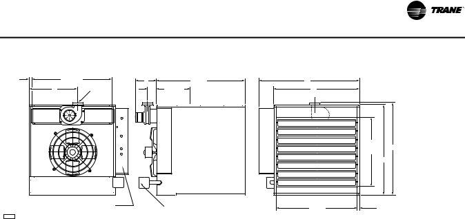
Figure 14. Unit sizes 150–400: Dimensions, standard units |
|
|
|
||||
1-3/8" |
E |
|
|
32-1/2" |
|
|
|
(35) |
D |
|
L |
|
|
||
(Hanging) |
(Hanging) |
11-5/8" |
(826) |
|
|
||
|
|
|
|
||||
C |
Flue * |
G |
(295) |
|
B |
|
|
|
|
|
(Hanging) |
|
|
|
|
|
|
|
|
|
|
H |
A |
|
|
|
|
|
|
(Discharge |
|
|
|
|
|
|
|
Opening) |
|
|
|
|
|
|
|
33" |
|
|
Electrical Control Panel |
|
Gas Valve |
|
F |
1" (25) |
|
|
|
|
|
|
|||
D4617 |
|
|
|
|
(Discharge Opening) |
|
|
|
|
|
|
|
|
|
|
Rear View |
Side View |
Front View |
GTND-SVX01B-EN |
15 |

Installation: Mechanical
NOTICE:
Equipment Damage!
Do not install unit heaters in corrosive or flammable atmospheres! Premature failure of, or severe damage to the unit could result! Avoid locations where extreme drafts can affect burner operation. Unit heaters must not be installed in locations where air for combustion would contain chlorinated, halogenated or acidic vapors. If located in such an environment, premature failure of the unit could occur!
Since the unit is equipped with an automatic gas ignition system, the unit heaters must be installed such that the gas ignition control system is not directly exposed to water spray, rain, or dripping water.
Additional Requirement for Canadian Installations
Refer to specification table and installation manual for proper usage.
The following instructions apply to Canadian installations in addition to installation and operating instructions:
1.Installation must conform with local building codes, or in the absence of local codes, with current CSA B149.1, “Installation Codes for Natural Gas Burning Appliances and Equipment”, or CSA B149.2, “Installation Codes for Propane Gas Burning Appliances and Equipment”.
2.Any reference to U. S. standards or codes in these instructions are to be ignored, and the applicable Canadian standards or codes applied.
Note: Location of unit heaters is related directly to the selection of sizes. Basic rules are as follows:
Mounting Height. Mounting height varies by unit size:
Unit sizes 30–120: If the unit heater is installed in a garage, it must be installed with a minimum clearance above the floor of 18 inches (457 mm).
Unit sizes 150–400: Unit heaters equipped with standard fan guards must be installed at a minimum of 8 feet (2.4 m) above the floor, measured to the bottom of the unit. At heights above 8 feet (2.4 m), less efficient air distribution will result. If a unit is to be mounted below 8 feet (2.4 m) from the floor, an OSHA approved fan guard is required on the unit.
Aircraft Hangers. Unit sizes 150–400: Unit heaters must be installed in aircraft hangars as follows: in aircraft hangars, unit heaters must be at least 10 feet (3.0 m) above the upper surface of wings or engine enclosures of the highest aircraft to be stored in the hangar, and 8 feet (2.4 m) above the floor in shops, offices and other sections of the hangar where aircraft are not stored or housed. Refer to current ANSI/NFPA No. 409, Aircraft Hangars. In
Canada, installation is suitable in aircraft hangars when acceptable to the enforcing authorities.
Public Garages. Unit sizes 150–400: In repair garages, unit heaters must be located at least 8 feet (2.4 m) above the floor. Refer to the latest edition of NFPA 88B, Repair Garages.
In parking structures, unit heaters must be installed so that the burner flames are located a minimum of 18 inches (457 mm) above the floor or protected by a partition not less than 18 inches (457 mm) high. However, any unit heater mounted in a parking structure less than 8 feet (2.4 m) above the floor must be equipped with an OSHA approved fan guard. Refer to the latest edition of
NFPA 88A, Parking Structures.
In Canada, installation must be in accordance with the latest edition of CSA-B149 “Installation Codes for Gas Burning Appliances and Equipment.”
Air Distribution
Direct air towards areas of maximum heat loss. When multiple heaters are involved, circulation of air around the perimeter is recommended where heated air flows along exposed walls. Satisfactory results can also be obtained where multiple heaters are located toward the center of the area with heated air directed toward the outside walls. Be careful to avoid all obstacles and obstructions which could impede the warm air distribution patterns.
NOTICE:
Maintain Minimum Thermostat Setting!
Unit heaters should not be installed to maintain low temperatures and/or freeze protection of buildings. A minimum of 50°F (10°C) thermostat setting must be maintained. If unit heaters are operated to maintain lower than 50°F (10°C), hot flue gases are cooled inside the heat exchanger to a point where water vapor (a flue gas by-product) condenses onto the heat exchanger walls. The result is a mildly corrosive acid that prematurely corrodes the aluminized heat exchanger and can actually drip water down from the unit heater onto the floor surface. Additional unit heaters should be installed if a minimum 50°F (10°C) thermostat setting cannot be maintained. Failure to follow these recommendations could result in equipment or property damage.
16 |
GTND-SVX01B-EN |
Loading...