


TL-WA5210G
2.4GHz High Power Wireless Outdoor CPE
Rev: 1.0.0 1910010274
COPYRIGHT & TRADEMARKS
Specifications are subject to change without notice.  is a registered trademark of TP-LINK TECHNOLOGIES CO., LTD. Other brands and product names are trademarks or registered trademarks of their respective holders.
No part of the specifications may be reproduced in any form or by any means or used to make any derivative such as translation, transformation, or adaptation without permission from TP-LINK TECHNOLOGIES CO., LTD. Copyright © 2010 TP-LINK TECHNOLOGIES CO., LTD.
All rights reserved.
http://www.tp-link.com

FCC STATEMENT
This equipment has been tested and found to comply with the limits for a Class B digital device, pursuant to part 15 of the FCC Rules. These limits are designed to provide reasonable protection against harmful interference in a residential installation. This equipment generates, uses and can radiate radio frequency energy and, if not installed and used in accordance with the instructions, may cause harmful interference to radio communications. However, there is no guarantee that interference will not occur in a particular installation. If this equipment does cause harmful interference to radio or television reception, which can be determined by turning the equipment off and on, the user is encouraged to try to correct the interference by one or more of the following measures:
•Reorient or relocate the receiving antenna.
•Increase the separation between the equipment and receiver.
•Connect the equipment into an outlet on a circuit different from that to which the receiver is connected.
•Consult the dealer or an experienced radio/ TV technician for help.
This device complies with part 15 of the FCC Rules. Operation is subject to the following two conditions:
1)This device may not cause harmful interference.
2)This device must accept any interference received, including interference that may cause undesired operation.
Any changes or modifications not expressly approved by the party responsible for compliance could void the user’s authority to operate the equipment.
Note: The manufacturer is not responsible for any radio or tv interference caused by unauthorized modifications to this equipment. Such modifications could void the user’s authority to operate the equipment.
FCC RF Radiation Exposure Statement
This equipment complies with FCC RF radiation exposure limits set forth for an uncontrolled environment. This device and its antenna must not be co-located or operating in conjunction with any other antenna or transmitter.
“To comply with FCC RF exposure compliance requirements, this grant is applicable to only Mobile Configurations. The antennas used for this transmitter must be installed to provide a separation distance of at least 20 cm from all persons and must not be co-located or operating in conjunction with any other antenna or transmitter.”
CE Mark Warning
This is a class B product. In a domestic environment, this product may cause radio interference, in which case the user may be required to take adequate measures.

National Restrictions
2400.0-2483.5 MHz
Country |
Restriction |
Reason/remark |
|
|
|
Bulgaria |
|
General authorization required for outdoor use |
|
and public service |
|
|
|
Outdoor use limited to 10 France mW e.i.r.p. within the
band 2454-2483.5 MHz
Military Radiolocation use. Refarming of the 2.4 GHz band has been ongoing in recent years to allow current relaxed regulation. Full implementation planned 2012
Italy |
|
If used outside of own premises, general |
|
|
authorization is required |
||
|
|
||
|
|
|
|
Luxembourg |
None |
General authorization required for network and |
|
service supply(not for spectrum) |
|||
|
|
||
|
|
|
|
|
|
This subsection does not apply for the |
|
Norway |
Implemented |
geographical area within a radius of 20 km from |
|
|
|
the centre of Ny-Ålesund |
|
|
|
|
|
Russian |
|
Only for indoor applications |
|
Federation |
|
|
Note: It’s not used outdoors in France.

 TP-LINK TECHNOLOGIES CO., LTD
DECLARATION OF CONFORMITY
For the following equipment:
Product Description: 2.4GHz High Power Wireless Outdoor CPE Model No.: TL-WA5210G
Trademark: TP-LINK
We declare under our own responsibility that the above products satisfy all the technical regulations applicable to the product within the scope of Council Directives:
Directives 1999/5/EC
The above product is in conformity with the following standards or other normative documents
ETSI EN 300 328 V1.7.1: 2006
ETSI EN 301 489-1 V1.8.1:2008& ETSI EN 301 489-17 V1.3.2:2008 EN 61000-3-2:2006
EN 61000-3-3:1995+A1:2001+A2:2005 EN60950-1:2006
Recommendation 1999/519/EC
EN62311:2008
Directives 2004/108/EC
The above product is in conformity with the following standards or other normative documents
EN 55022:2006 +A1:2007
EN 55024:1998+A1:2001+A2:2003 EN 61000-3-2:2006
EN 61000-3-3:1995+A1:2001+A2:2005
Directives 2006/95/EC
The above product is in conformity with the following standards or other normative documents
EN60950-1:2006
Person is responsible for marking this declaration:
Yang Hongliang
Product Manager of International Business
TP-LINK TECHNOLOGIES CO., LTD.
South Building, No.5 Keyuan Road, Central Zone, Science & Technology Park, Nanshan,
Shenzhen, P. R. China
|
|
CONTENTS |
|
Package Contents ................................................................................................................................. |
1 |
||
Chapter 1 |
Product Overview........................................................................................................... |
2 |
|
1.1 |
Overview of the Product........................................................................................................... |
2 |
|
1.2 |
Features................................................................................................................................... |
2 |
|
1.3 |
Conventions ............................................................................................................................. |
3 |
|
Chapter 2 |
Hardware Installation..................................................................................................... |
4 |
|
2.1 |
LED Explanation ...................................................................................................................... |
4 |
|
2.2 |
Interfaces and button ............................................................................................................... |
4 |
|
2.3 |
System Requirements.............................................................................................................. |
5 |
|
2.4 |
Environment Requirements ..................................................................................................... |
5 |
|
2.5 |
Connecting the Device............................................................................................................. |
5 |
|
Chapter 3 |
Quick Installation Guide ................................................................................................ |
7 |
|
3.1 |
Configure the Device ............................................................................................................... |
7 |
|
3.2 |
Quick Setup ............................................................................................................................. |
8 |
|
Chapter 4 |
AP Client Router & AP Router Operation Mode........................................................ |
13 |
|
4.1 |
Login ...................................................................................................................................... |
13 |
|
4.2 |
Status..................................................................................................................................... |
13 |
|
4.3 |
Quick Setup ........................................................................................................................... |
15 |
|
4.4 |
Operation Mode ..................................................................................................................... |
15 |
|
4.5 |
Network.................................................................................................................................. |
15 |
|
4.5.1 |
LAN................................................................................................................................. |
16 |
|
4.5.2 |
WAN ............................................................................................................................... |
16 |
|
4.5.3 |
MAC Clone ..................................................................................................................... |
21 |
|
4.6 |
Wireless ................................................................................................................................. |
21 |
|
4.6.1 |
Basic Settings................................................................................................................. |
22 |
|
4.6.2 |
Wireless Mode................................................................................................................ |
23 |
|
4.6.3 |
Security Settings ............................................................................................................ |
26 |
|
4.6.4 |
MAC Filtering.................................................................................................................. |
28 |
|
4.6.5 |
Wireless Statistics .......................................................................................................... |
30 |
|
4.6.6 |
Distance Setting ............................................................................................................. |
30 |
|
4.6.7 |
Antenna Alignment ......................................................................................................... |
31 |
|
4.6.8 |
Throughput Monitor........................................................................................................ |
32 |
|
4.7 |
DHCP..................................................................................................................................... |
32 |
|
4.7.1 |
DHCP Settings ............................................................................................................... |
33 |
|
4.7.2 |
DHCP Clients List........................................................................................................... |
34 |
|
4.7.3 |
Address Reservation...................................................................................................... |
34 |
|
4.8 |
Wireless settings.................................................................................................................... |
35 |
|
4.9 |
Forwarding ............................................................................................................................. |
36 |
|
4.9.1 |
Virtual Servers................................................................................................................ |
37 |
|
4.9.2 |
Port Triggering................................................................................................................ |
38 |
|
4.9.3 |
DMZ................................................................................................................................ |
40 |
|
4.9.4 |
UPnP .............................................................................................................................. |
41 |
|
4.10 |
Security .................................................................................................................................. |
41 |
|
4.10.1 |
Firewall ........................................................................................................................... |
42 |
|
4.10.2 |
IP Address Filtering ........................................................................................................ |
43 |
|
4.10.3 |
Domain Filtering ............................................................................................................. |
44 |
|
4.10.4 |
MAC Address Filtering ................................................................................................... |
46 |
|
4.10.5 |
Remote Management..................................................................................................... |
47 |
|
4.10.6 |
Advanced Security ......................................................................................................... |
48 |
|
4.11 |
Static Routing......................................................................................................................... |
50 |
|
4.12 IP & MAC Binding .................................................................................................................. |
51 |
||
4.12.1 |
Binding Setting ............................................................................................................... |
51 |
|
4.12.2 |
ARP List.......................................................................................................................... |
52 |
|
4.13 |
Dynamic DNS ........................................................................................................................ |
53 |
|
4.13.1 |
Dyndns.org DDNS.......................................................................................................... |
53 |
|
4.13.2 |
Oray.net DDNS .............................................................................................................. |
54 |
|
4.13.3 |
Comexe.cn DDNS .......................................................................................................... |
55 |
|
4.14 |
SNMP..................................................................................................................................... |
56 |
|
4.14.1 |
Community Setting ......................................................................................................... |
56 |
|
4.14.2 |
SNMP System Setting.................................................................................................... |
57 |
|
4.15 |
System Tools ......................................................................................................................... |
58 |
|
4.15.1 |
Time................................................................................................................................ |
58 |
|
4.15.2 |
Firmware......................................................................................................................... |
59 |
|
4.15.3 |
Factory Defaults ............................................................................................................. |
60 |
|
4.15.4 |
Backup & Restore .......................................................................................................... |
61 |
|
4.15.5 |
Ping Watch Dog ............................................................................................................. |
61 |
|
4.15.6 |
Speed Test ..................................................................................................................... |
62 |
|
4.15.7 |
Reboot............................................................................................................................ |
63 |
|
4.15.8 |
Password........................................................................................................................ |
64 |
|
4.15.9 |
Syslog............................................................................................................................. |
64 |
|
4.15.10 |
Statistics ..................................................................................................................... |
65 |
|
Chapter 5 |
AP Operation Mode...................................................................................................... |
67 |
|
5.1 |
Login ...................................................................................................................................... |
67 |
|
5.2 |
Status..................................................................................................................................... |
67 |
|
II
5.3 |
Quick Setup ........................................................................................................................... |
68 |
|
5.4 |
Operation Mode ..................................................................................................................... |
69 |
|
5.5 |
Network.................................................................................................................................. |
69 |
|
5.6 |
Wireless ................................................................................................................................. |
70 |
|
5.6.1 |
Basic Settings................................................................................................................. |
70 |
|
5.6.2 |
Wireless Mode................................................................................................................ |
72 |
|
5.6.3 |
Security Settings ............................................................................................................ |
76 |
|
5.6.4 |
MAC Filtering.................................................................................................................. |
79 |
|
5.6.5 |
Wireless Statistics .......................................................................................................... |
81 |
|
5.6.6 |
Distance Setting ............................................................................................................. |
82 |
|
5.6.7 |
Antenna Alignment ......................................................................................................... |
82 |
|
5.6.8 |
Throughput Monitor........................................................................................................ |
83 |
|
5.7 |
DHCP..................................................................................................................................... |
83 |
|
5.7.1 |
DHCP Settings ............................................................................................................... |
84 |
|
5.7.2 |
DHCP Clients List........................................................................................................... |
85 |
|
5.7.3 |
Address Reservation...................................................................................................... |
85 |
|
5.8 |
Wireless settings.................................................................................................................... |
87 |
|
5.9 |
SNMP..................................................................................................................................... |
87 |
|
5.9.1 |
Community Setting ......................................................................................................... |
88 |
|
5.9.2 |
SNMP System Setting.................................................................................................... |
89 |
|
5.10 |
System Tools ......................................................................................................................... |
89 |
|
5.10.1 |
Firmware......................................................................................................................... |
90 |
|
5.10.2 |
Factory Defaults ............................................................................................................. |
90 |
|
5.10.3 |
Backup & Restore .......................................................................................................... |
91 |
|
5.10.4 |
Ping Watch Dog ............................................................................................................. |
91 |
|
5.10.5 |
Speed Test ..................................................................................................................... |
92 |
|
5.10.6 |
Reboot............................................................................................................................ |
93 |
|
5.10.7 |
Password........................................................................................................................ |
94 |
|
5.10.8 |
Syslog............................................................................................................................. |
94 |
|
Appendix A: FAQ ................................................................................................................................ |
96 |
||
Appendix B: Configuring the PC ..................................................................................................... |
100 |
||
Appendix C: Specifications.............................................................................................................. |
104 |
||
Appendix D: Glossary....................................................................................................................... |
105 |
||
III
Package Contents
The following items should be found in your package:
¾One TL-WA5210G 2.4GHz High Power Wireless Outdoor CPE
¾One AC power Adapter for TL-WA5210G 2.4GHz High Power Wireless Outdoor CPE
¾One Power Injector
¾Quick Installation Guide
¾One Resource CD for TL-WA5210G 2.4GHz High Power Wireless Outdoor CPE, including: z This User Guide
z Other helpful information
) Note:
Make sure that the package contains the above items. If any of the listed items are damaged or missing, please contact your distributor.
1
Chapter 1 Product Overview
Thank you for choosing TL-WA5210G 2.4GHz High Power Wireless Outdoor CPE
1.1Overview of the Product
The TL-WA5210G 2.4GHz High Power Wireless Outdoor CPE is dedicated to Outdoor wireless network solutions. The TL-WA5210G 2.4GHz High Power Wireless Outdoor CPE will allow you to connect your network with other wireless devices wirelessly, sharing Internet Access, files and fun, easily and securely. The high power design will also help you build a more stable link or cover more area outdoors.
The TL-WA5210G 2.4GHz High Power Wireless Outdoor CPE provides 3 operation modes for multi-user to access the Internet: AP client router, AP router and AP. In AP client router mode, it works as a WISP CPE and can access the Internet wirelessly via your WISP. In AP router mode, it can access the Internet via an ADSL/Cable Modem, while sharing data wirelessly. In AP mode it can work in various modes, such as Access Point/Client/WDS Bridge/Repeater.
With the most attentive wireless security, the TL-WA5210G 2.4GHz High Power Wireless Outdoor CPE provides multiple protection measures. It can be set to turn off wireless network name (SSID) broadcast so that only stations that have the SSID can be connected. The AP provides wireless LAN 64/128/152-bit WEP encryption security, and WPA/WPA2 and WPA-PSK/WPA2-PSK authentication, as well as TKIP/AES encryption security. It also supports VPN pass-through for sensitive data secure transmission.
The TL-WA5210G 2.4GHz High Power Wireless Outdoor CPE complies with the IEEE 802.11g and IEEE 802.11b standards so that the data transmission rate is up to 54Mbps. The wireless transmission range can extend up to tens of kilometers.
1.2Features
¾Complies with IEEE 802.11g, IEEE 802.11b, IEEE 802.3, IEEE 802.3u standards.
¾Wireless Data transfer rates up to 54Mbps.
¾Supports AP Client Router, AP Router and AP operation mode.
¾High output transmit power and receive sensitivity optimized.
¾Supports Client Router Mode for WISP CPE
¾Supports passive power over Ethernet.
¾Supports Wireless Distribution System (WDS).
¾ACK timeout adjustment for long range transmission, up to 50km.
¾Supports Antenna Alignment.
¾Provides throughput monitor indicating the current wireless throughput.
¾Supports Layer 2 User Isolation.
¾Supports Ping Watch Dog.
¾Supports link speed test.
¾Supports Remote Management
¾Output transmit power adjustable.
¾Supports PPPoE, Dynamic IP, Static IP Internet Access.
2
¾Built-in NAT and DHCP server supporting static IP address distributing.
¾Supports UPnP, Dynamic DNS, Static Routing, VPN Pass-through.
¾Supports Virtual Server, Special Application and DMZ host.
¾Built-in firewall supporting IP address filtering, Domain Name filtering, and MAC address filtering.
¾Provides WLAN ACL (Access Control List).
¾Supports configuration backup/restore and firmware upgrade.
¾Supports Web management.
1.3Conventions
The AP or TL-WA5210G, or device mentioned in this User guide stands for TL-WA5210G 2.4GHz High Power Wireless Outdoor CPE without any explanations.
Parameters provided in the pictures are just references for setting up the product, which may differ from the actual situation.
You can set the parameters according to your demand.
3
Chapter 2 Hardware Installation
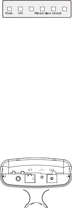
2.1LED Explanation
TL-WA5210G consists of several LED indicators, which is designed to indicate connections and wireless signal.
|
|
|
|
|
|
|
|
|
|
|
|
|
|
|
|
|
|
|
|
|
|
|
|
|
|
|
|
|
|
|
|
|
|
|
|
|
|
|
|
|
|
|
|
|
|
|
|
|
|
|
|
|
|
|
|
|
|
|
|
|
|
|
|
|
|
|
|
|
Figure 2-1 Front Panel sketch |
|
|||||||||
|
View from left to right. |
|
|
|
|
|
|
|
|
|
|
|
|
||
|
Name |
|
Status |
|
|
|
|
|
|
|
Indication |
|
|||
|
Power |
|
Off |
No Power |
|
||||||||||
|
|
|
|
|
|
|
|
|
|
|
|
|
|
|
|
|
|
On |
|
Power on |
|
||||||||||
|
|
|
|
|
|||||||||||
|
|
|
|
|
|
|
|
||||||||
|
|
|
Off |
There is no device linked to the corresponding port |
|
||||||||||
|
LAN |
|
|
|
|
|
|
|
|||||||
|
|
On |
|
There is a device linked to the corresponding port but no activity |
|||||||||||
|
|
|
|
|
|
|
|
||||||||
|
|
|
Flashing |
There is an active device linked to the corresponding port |
|
||||||||||
|
|
|
|
|
|
|
|
||||||||
|
Wireless |
|
Off |
There is no remote wireless signal |
Client or |
||||||||||
|
Signal |
|
|
|
|
|
|
|
|
|
|
|
|
|
Repeater |
|
|
On |
|
Indicates the wireless signal strength of a remote AP |
|||||||||||
|
Strength |
|
|
mode |
|||||||||||
|
|
|
|
|
|
|
|
|
|
|
|
|
|
|
|
Table 2-1
) Note:
For Wireless Signal Strength LEDs:
¾In AP or Bridge mode, all the four LEDs will light up.
¾In Client or Repeater mode, the corresponding LED(s) will light up when the RSSI value (wireless signal strength value) reaches the RSSI Threshold. The value of RSSI Threshold can be set on Wireless Advanced Settings page as shown in Figure 4-26.
For example, if the RSSI value is 30, the RSSI Threshold of the four LED are 15, 25, 35, 45 respectively, and then the LEDs whose RSSI Threshold are 15 and 25 will light up.
2.2Interfaces and button
Figure 2-2 Rear Panel sketch
View from left to right, the parts are explained below.
4
¾ : This is where you can connect an outside antenna. For this AP, the antenna is built inside, and usually there is not necessary to connect an outside one.
¾LAN: This port is used to connect to the POE port of the provided Power Injector.
¾RESET:
There are two ways to reset the AP's factory defaults:
•Use the Factory Defaults function on System Tools -> Factory Defaults page in the AP's Web-based Utility.
•Use the Factory Default Reset button: Press and hold the RESET button for at least 5 seconds, and then the AP reboots after the LED at the rightmost in Figure 2-1 flashes.
) Note:
Ensure the AP is powered on before it restarts completely.
2.3System Requirements
¾Each PC in the LAN needs a working Ethernet Adapter and an Ethernet cable with RJ45 connectors
¾TCP/IP protocol must be installed on each PC
¾Web browser, such as Microsoft Internet Explorer 5.0 or later, Netscape Navigator 6.0 or later
¾If the device is configured to AP client router mode, you also need:
Wireless Internet Access Service (WISP).
¾If the device is configured to AP router mode, you also need: Broadband Internet Access Service (DSL/Cable/Ethernet)
¾One DSL/Cable Modem that has an RJ45 connector (you do not need it if you connect the router to the Ethernet)
2.4Environment Requirements
¾Do not place in direct sunlight or near a heater or heating vent
¾Do not cluttered or crowded. There should be at least 2 inches (5 cm) of clear space on all sides of the router
¾Well ventilated (especially if it is in a closet)
¾Operating temperature: -20 ~65
¾Operating Humidity: 10%~90% RH, Non-condensing
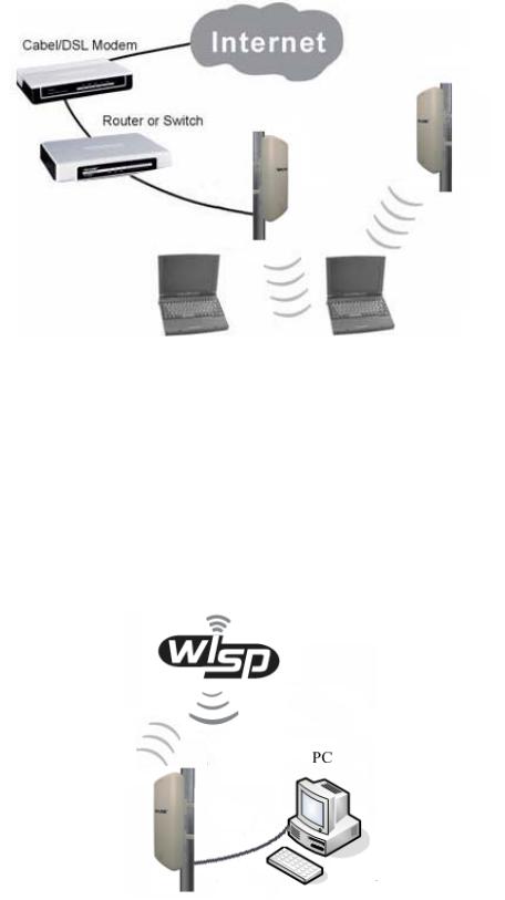
2.5Connecting the Device
Figure 2-3 is an example of an infrastructure network incorporating the TL-WA5210G. An Infrastructure network contains an access point or a wireless router. To establish an infrastructure network in AP mode, please take the following steps:
1.You will need broadband Internet access (a Cable or DSL-subscriber line into your home or office). Consult with your Cable or DSL provider for proper installation of the modem.
2.Connect the Cable or DSL modem to a Router. Quickly install the router.
3.Locate an optimum location for the AP. Choose an elevated location where trees, buildings and large steel structures will not obstruct the antenna signals and which offers maximum line
5
of sight propagation with the users. The place must accord with the Installation Environment Requirements.
4.Adjust the direction of the AP to get a best signal.
5.Connect the Ethernet Broadband Router to the TL-WA5210G AP. Power on the AP.
6.If you are connecting a desktop PC or laptop to your network, install the TP-LINK Wireless Adapter on the PC.
Figure 2-3
To establish an infrastructure network in AP Client Router mode as Figure 2-4, please take the following steps:
1.Make sure you are provided with wireless Internet service by your WISP (Wireless Internet Service Provider).
2.Locate an optimum location for the AP. Try to place your AP in an appropriate position where it can well receive the signal from WISP.
3.Connect the AP to the desktop PC.
4.Adjust the direction of the AP to get a best signal.
5.Power on the AP and then you can configure the AP on the web-based page on your computer.
Figure 2-4
6
Chapter 3 Quick Installation Guide
This Chapter will guide you to configure the AP to function in your network and gain access to the internet through your ISP immediately after successful configuration. More detailed description of the AP’s web-based utility and functions can be found in “Chapter 4 Configuring the AP”
3.1Configure the Device
The instructions in this section will help you configure each of your PCs to be able to communicate with the AP.
The default IP address of the TL-WA5210G 2.4GHz High Power Wireless Outdoor CPE is 192.168.1.254. And the default Subnet Mask is 255.255.255.0. These values can be seen from the LAN. They can be changed as you desire, as an example we use the default values for description in this guide.
Connect the local PC to the LAN ports of the AP. There are then two ways to configure the IP address for your PC.
¾Configure the IP address manually
1)Set up the TCP/IP Protocol for your PC. If you need instructions as to how to do this, please refer to Appendix2 B: Configuring the PC
2)Configure the network parameters. The IP address is 192.168.1.xxx ("xxx" is from 1 to 253), Subnet Mask is 255.255.255.0, and Gateway is 192.168.1.254 (The AP's default IP address)
¾Obtain an IP address automatically
This method can be available only when DHCP in section 4.7.1 is enabled.
1)Set up the TCP/IP Protocol in "Obtain an IP address automatically" mode on your PC. If you need instructions as to how to do this, please refer to Appendix B: Configuring the PC.
2)Power off the AP and PC. Then turn on the AP and restart the PC. The built-in DHCP server will assign IP address for the PC.
) Note:
For Windows 98 OS or earlier, the PC and AP may need to be restarted.
Now, you can run the Ping command in the command prompt to verify the network connection between your PC and the AP. The following example is in Windows 2000 OS.
Open a command prompt, and type ping 192.168.1.254, and then press Enter.
If the result displayed is similar to that shown in Figure 3-1, the connection between your PC and the AP has been established.
7

Figure 3-1 Success result of Ping command
If the result displayed is similar to that shown in Figure 3-2, it means that your PC has not connected to the AP.
Figure 3-2 Failure result of Ping command
Please check the connection following these steps:
1.Is the connection between your PC and the AP correct?
) Note:
The LED of LAN port you link to on the AP and LEDs on your PC's adapter should be lit.
2.Is the TCP/IP configuration for your PC correct?
) Note:
If the AP's IP address is 192.168.1.254, your PC's IP address must be within the range of 192.168.1.1 ~ 192.168.1.253, the gateway must be 192.168.1.254.
3.2Quick Setup
The following instructions will guide you through a few easy steps to configure your AP and connect to Internet. With a Web-based (Internet Explorer or Netscape® Navigator) utility, it is easy to configure and manage the TL-WA5210G 2.4GHz High Power Wireless Outdoor CPE. The Web-based utility can be used on any Windows, Macintosh or UNIX OS with a Web browser.
Open your web browser and enter the IP address of the AP (192.168.1.254) and a login screen will display (shown in Figure 3-3).
Figure 3-3 Login the router
Enter admin for Username and Password (both in lower case letters) on the following login screen. Click OK or press Enter of your keyboard, and the management page will display.
8

Figure 3-4 Login Windows
) Note:
If the above screen does not pop-up, it means that your Web-browser has been set to a proxy. Go to Tools menu>Internet Options>Connections>LAN Settings, in the screen that appears, cancel the Using Proxy checkbox, and click OK to finish it.
If the User Name and Password are correct, you can configure the AP using the Web browser. Please click the Quick Setup link on the left of the main menu and the Quick Setup screen will appear.
Figure 3-5 Quick Setup
Click Next, and then Choose Operation mode page will appear, shown in Figure 3-6:
Figure 3-6 Choose Operation mode
9
) Note:
The AP supports three mode operation modes for multi-user to access the Internet: AP Client Router, AP Router and AP. In AP Client Router mode, it can access the Internet wirelessly by your WISP’s support. In AP Router mode, it can access the Internet via ADSL/Cable Modem. In AP mode, it can access a wireless network by using WIFI. You can configure your device quickly by the following steps in different modes.
A.When you choose AP Client Router or AP Router mode, take the following steps:
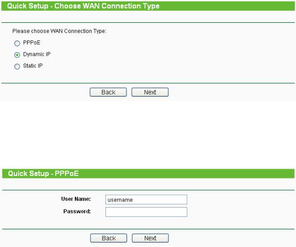
1.click Next in Figure 3-6, and then Choose WAN Connection Type page will appear, shown in Figure 3-7:
Figure 3-7 Choose WAN Connection Type
The AP in AP Client Router and AP Router mode supports three popular ways to connect to the Internet. Please select one compatible with your ISP.
2. Click Next in Figure 3-7 to enter the necessary network parameters.
a)If you choose "PPPoE", you will see this page shown in Figure 3-8:
Figure 3-8 Quick Setup - PPPoE
¾Account Name and Password - Enter the Account Name and Password provided by your ISP. These fields are case sensitive. If you have difficulty with this process, please contact your ISP.
b)If you choose "Dynamic IP", the router will automatically receive the IP parameters from your ISP without needing to enter any parameters.
c)If you Choose "Static IP", the Static IP settings page will appear, shown in Figure 3-9:
10
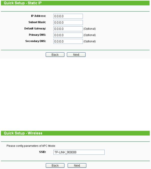
Figure 3-9 Quick Setup - Static IP
) Note:
The IP parameters should have been provided by your ISP.
¾IP Address - This is the WAN IP address as seen by external users on the Internet (including your ISP). Enter the IP address into the field.
¾Subnet Mask - The Subnet Mask is used for the WAN IP address, it is usually 255.255.255.0.
¾Default Gateway - Enter the gateway IP address into the box if required.
¾Primary DNS - Enter the DNS Server IP address into the boxes if required.
¾Secondary DNS - If your ISP provides another DNS server, enter it into this field.
3. After you complete the above, click Next, the Wireless settings page will appear below.
Figure 3-10 Quick Setup - Wireless settings
On this page, you can configure the following wireless parameters:
) Note:
The Quick Setup - Wireless page differs in different modes. If you choose the AP Router mode, you will see the Wireless page as below.
11

Figure 3-11 Quick Setup - Wireless settings
¾SSID - Enter a value of up to 32 characters. The same SSID must be assigned to all wireless devices on your network. The default SSID is TP-LINK_XXXXXX This value is case-sensitive. For example, TEST is NOT the same as test.
¾Region - Specifies the region where the wireless function of the AP can be used. Select your region from the drop-down list. The default is United States. If your country or region is not listed, please contact your local government agency for assistance.
) Note:
Restricted by local law regulations, version for North America does not have region selection option. The wireless basic settings for this version are shown below.
¾Channel - The current channel in use. This field determines which operating frequency will be used.
¾Mode - Indicates the current mode 54Mbps (802.11g), 11Mbps (802.11b). If you select
54Mbps (802.11g), it is compatible with 11Mbps (802.11b).
These settings are only for basic wireless parameters, for advanced settings, please refer to Section 4.6: "Wireless".
B.When you choose AP mode on Quick Setup - Choose Operation Mode page (shown as Figure 3-6), you will directly go to the Wireless page as Figure 3-11 above.
Click the Next button. You will then see the Finish page:
Figure 3-12 Quick Setup - Finish
After finishing all configurations of basic network parameters, please click Finish button to exit this Quick Setup and wait your device reboot automatically. The changes of settings will take effect after rebooting.
12
Chapter 4 AP Client Router & AP Router Operation Mode
This Chapter describes how to configure some advanced settings for your Access Point through the web-based management page. In the following explanations, we will take the device in AP Client Router operation mode for example.
4.1Login
After your successful login, you can configure and manage the Access Point. There are fourteen main menus on the left of the Web-based management page. Submenus will be available after you click one of the main menus. The fourteen main menus are: Status, Quick Setup, Operation Mode, Network, Wireless, DHCP, Wireless Settings, Forwarding, Security, Static Routing, IP & MAC Binding, Dynamic DNS, SNMP and System Tools. On the right of the Web-based management page, there are the detailed explanations and instructions for the corresponding page. To apply any settings you have altered on the page, please click Save.
The detailed explanations for each Web page key’s function are listed below.
4.2Status
Selecting Status will enable you to view the AP’s current status and configuration, all of which is read-only.
13
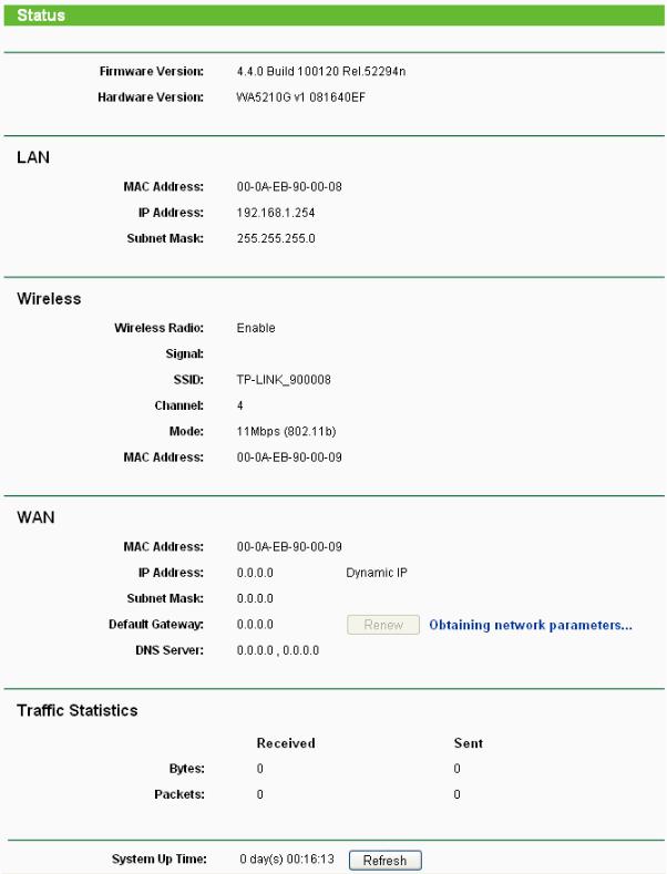
Figure 4-1 Status
1.LAN
This field displays the current settings or information for the LAN, including the MAC address, IP address and Subnet Mask.
2.Wireless
This field displays basic information or status for wireless function, including Wireless Radio,
SSID, Channel, Mode, and Wireless MAC address.
14

3.WAN
These parameters apply to the WAN port of the router, including MAC address, IP address, Subnet Mask, Default Gateway and DNS server. If PPPoE is chosen as the WAN connection type, the Disconnect button will be shown here while you are accessing the Internet. You can also cut the connection by clicking the button. If you have not connected to the Internet, just click Connect to establish the connection.
4.Traffic Statistics
This field displays the router's traffic statistics.
5.System Up Time
The total up time of the router since it was powered on or reset.
4.3Quick Setup
Please refer to Section 3.2: "Quick Setup".
4.4Operation Mode
Selecting Operation Mode will allow you to choose the operation mode for the AP. The AP supports three operation mode types, AP Client Router, AP Router and AP. Please select the one your want as shown in Figure 4-2. Click Save to save your choice.
Figure 4-2 Operation Mode
¾AP Client Router - In this mode, the device enables multi-user to share the Internet from WISP. All LAN ports share the same IP from WISP through Wireless port. While connecting to WISP, the Wireless port works as a WAN port in AP Client mode. The Ethernet port acts as a LAN port.
¾AP Router - In this mode, the device enables multi-user to share the Internet via ADSL/Cable Modem. The wireless port share the same IP to ISP through Ethernet WAN port. The Wireless port acts same as a LAN port while in AP mode.
¾AP - In this mode, the device allows wireless communication devices to access a wireless network by using WIFI. The Ethernet port and the wireless port both work as LAN ports.
4.5Network
The Network option allows you to customize your local network manually by changing the default settings of the AP.
There are three submenus under the Network menu (shown in Figure 4-3): LAN, WAN and MAC Clone. Click any of them, and you will be able to configure the corresponding function. The
15

detailed explanations for each submenu are provided below.
Figure 4-3 the Network menu
4.5.1LAN
Selecting Network > LAN will enable you to configure the IP parameters of LAN port on this page.
Figure 4-4 LAN
¾MAC Address - The physical address of the router, as seen from the LAN. The value can't be changed.
¾IP Address - Enter the IP address of your router in dotted-decimal notation (factory default: 192.168.1.254).
¾Subnet Mask - An address code that determines the size of the network. Normally use 255.255.255.0 as the subnet mask.
) Note:
1)If you change the IP Address of LAN, you must use the new IP Address to login the Router.
2)If the new LAN IP Address you set is not in the same subnet, the IP Address pool of the DHCP server will not take effect until they are re-configured.
3)If the new LAN IP Address you set is not in the same subnet, the Virtual Server and DMZ Host will change accordingly at the same time.
4.5.2WAN
Selecting Network > WAN will enable you to configure the IP parameters of WAN port on this page.
First, please choose the WAN Connection Type (Dynamic IP/Static IP/PPPoE) for the Internet. The default type is Dynamic IP. If you aren’t given any login parameters (fixed IP Address, logging ID, etc), please select Dynamic IP. If you are given a fixed IP (static IP), please select Static IP. If you are given a user name and a password, please select the type of your ISP provided (PPPoE). If you are not sure which connection type you use currently, please contact your ISP to obtain the correct information.
1.If you choose Dynamic IP, the router will automatically get IP parameters from your ISP. You can see the page as shown in Figure 4-5.
16

Figure 4-5 WAN – Dynamic IP
This page displays the WAN IP parameters assigned dynamically by your ISP, including IP address, Subnet Mask, Default Gateway, etc. Click Renew to renew the IP parameters from your ISP. Click Release to release the IP parameters.
¾MTU Size - The normal MTU (Maximum Transmission Unit) value for most Ethernet networks is 1500 Bytes. For some ISPs you need to reduce the MTU. But this is rarely required, and should not be done unless you are sure it is necessary for your ISP connection.
If your ISP gives you one or two DNS addresses, select Use These DNS Servers and enter the primary and secondary addresses into the correct fields. Otherwise, the DNS servers will be assigned dynamically from your ISP.
) Note:
If you get address and find error when you go to a Web site, it is likely that your DNS servers are set up improperly. You should contact your ISP to get DNS server addresses.
¾Get IP with Unicast DHCP - A few ISPs' DHCP servers do not support the broadcast applications. If you cannot get the IP Address normally, you can choose this option. (This is rarely required.)
2.If you choose Static IP, you should have fixed IP Parameters specified by your ISP. The Static IP settings page will appear as shown in Figure 4-6.
17

Figure 4-6 WAN - Static IP
You should type the following parameters into the spaces provided:
¾IP Address - Enter the IP address in dotted-decimal notation provided by your ISP.
¾Subnet Mask - Enter the subnet Mask in dotted-decimal notation provided by your ISP, usually is 255.255.255.0.
¾Default Gateway - (Optional) Enter the gateway IP address in dotted-decimal notation provided by your ISP.
¾MTU Size - The normal MTU (Maximum Transmission Unit) value for most Ethernet networks is 1500 Bytes. For some ISPs you may need to modify the MTU. But this is rarely required, and should not be done unless you are sure it is necessary for your ISP connection.
¾Primary DNS - (Optional) Enter the DNS address in dotted-decimal notation provided by your ISP.
¾Secondary DNS - (Optional) Type another DNS address in dotted-decimal notation provided by your ISP if provided.
3.If you choose PPPoE, you should enter the following parameters as shown in Figure 4-7.
18
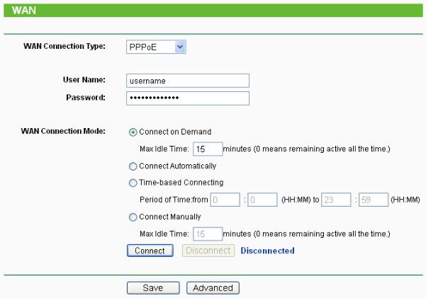
Figure 4-7 WAN - PPPoE
¾User Name/Password - Enter the User Name and Password provided by your ISP. These fields are case-sensitive.
¾Connect on Demand - You can configure the router to disconnect your Internet connection after a specified period of inactivity (Max Idle Time). If your Internet connection has been terminated due to inactivity, Connect on Demand enables the router to automatically re-establish your connection as soon as you attempt to access the Internet again. If you wish to activate Connect on Demand, click the radio button. If you want your Internet connection to remain active at all times, enter 0 in the Max Idle Time field. Otherwise, enter the number of minutes you want to have elapsed before your Internet connection terminates.
Caution: Sometimes the connection cannot be disconnected although you specify a time to Max Idle Time, since some applications is visiting the Internet continually in the background.
¾Connect Automatically - Connect automatically after the router is disconnected. To use this option, click the radio button.
¾Time-based Connecting - You can configure the router to make it connect or disconnect based on time. Enter the start time in HH:MM format for connecting and end time in HH:MM format for disconnecting in the Period of Time fields.
) Note:
Only when you have configured the system time on System Tools -> Time page, will the Time-based Connecting function can take effect.
¾Connect Manually - You can configure the router to make it connect or disconnect manually. After a specified period of inactivity (Max Idle Time), the router will disconnect from the Internet connection, and you will not be able to re-establish your connection automatically as soon as you attempt to access the Internet again. To use this option, click the radio button. If you want your Internet connection to remain active at all times, enter "0" in the Max Idle Time
19
field. Otherwise, enter the number time in minutes that you wish to have the Internet connecting last unless a new link is requested.
Caution: Sometimes the connection cannot be disconnected although you specify a time to Max Idle Time, since some applications are visiting the Internet continually in the background.
Click the Connect button to connect immediately, Click the Disconnect button to disconnect immediately.
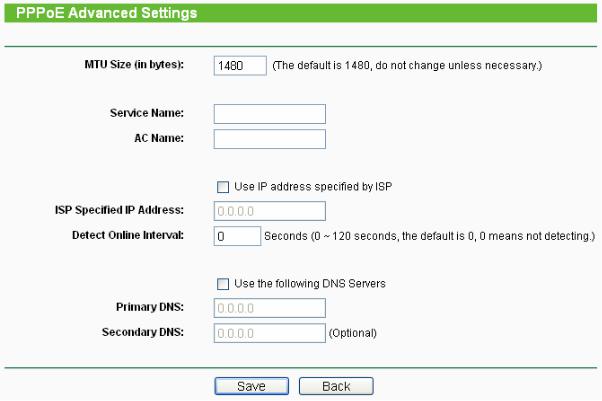
Click the Advanced Settings button to set up the advanced option, the page shown in Figure 4-8 will then appear.
Figure 4-8 PPPoE Advanced Settings
¾Packet MTU - The default MTU size is 1480 bytes, which value is usually fine. For some ISPs, you need modify the MTU. This should not be done unless you are sure it is necessary for your ISP.
¾Service Name/AC Name - The service name and AC (Access Concentrator) name, these should not be configured unless you are sure it is necessary for your ISP.
¾ISP Specified IP Address - If you know that your ISP does not automatically transmit your IP address to the router during login, click “Use the IP Address specified by ISP” check box and enter the IP Address in dotted-decimal notation, which your ISP provided.
¾Detect Online Interval - The default value is 0, you can input the value between 0 and 120. The router will detect Access Concentrator online at every interval between seconds. If the value is 0, it means, do not detect.
¾DNS IP address - If you know that your ISP does not automatically transmit DNS addresses to the router during login, click “Use the following DNS servers” checkbox and enter the IP address in dotted-decimal notation of your ISP’s primary DNS server. If a secondary DNS server address is available, enter it as well.
Click the Save button to save your settings.
20

4.5.3MAC Clone
MAC Clone allows you to clone the MAC address of the managing PC’s adapter to the WAN port. This is because some ISPs require that you register the MAC address of your adapter. Usually, you do not need to change anything here.
Selecting Network > MAC Clone will enable you to configure the MAC address of the WAN port on this page as shown in Figure 4-9.
Figure 4-9 MAC Address Clone
Some ISPs require that you register the MAC Address of your adapter, which is connected to your cable/DSL Modem or Ethernet during installation. Changes are rarely needed here.
¾WAN MAC Address - This field displays the current MAC address of the WAN port, which is used for the WAN port. If your ISP requires that you register the MAC address, please enter the correct MAC address into this field. The format for the MAC Address is XX-XX-XX-XX-XX-XX (X is any hexadecimal digit).
¾Your PC's MAC Address - This field displays the MAC address of the PC that is managing the router. If the MAC address is required, you can click the Clone MAC Address To button and this MAC address will fill in the WAN MAC Address field.
Click Restore Factory MAC to restore the MAC address of WAN port to the factory default value.
Click Save to save your settings.
) Note:
1)Only the PC on your LAN can use the Clone MAC Address To feature.
2)If you click Save, the Router will prompt you to reboot.
4.6Wireless
The Wireless option, improving functionality and performance for wireless network, can help you to make the AP an ideal solution for your wireless network.
Here you can create a wireless local area network just through a few settings. Basic Settings is used for the configuration of some basic parameters of the AP. Wireless Mode allows you to select the mode that AP works on. Security Settings provides three different security types to secure your data and thus provide greater security for your wireless network. MAC filtering allows you to control the access of wireless stations to the AP. Wireless Statistics shows you the statistics of current connected Wireless stations. Distance Setting is used to adjust the wireless range in outdoor conditions. Antenna Alignment shows how remote AP's signal strength changes while changing the antenna's direction. Throughput Monitor helps to watch wireless throughput information Wireless statistics enables you to get detailed information about the current connected wireless stations.
There are eight submenus under the Wireless menu (shown in Figure 4-10): Basic Settings,
21

Wireless Mode, Security Settings, MAC Filtering, Wireless Statistics, Distance Setting,
Antenna Alignment and Throughput Monitor. Click any of them, and you will be able to configure the corresponding function. The detailed explanations for each submenu are provided below.
Figure 4-10 Wireless menu
4.6.1Basic Settings
Selecting Wireless > Basic Settings will enable you to configure the basic settings for your wireless network on the screen below (Figure 4-11).
Figure 4-11 Wireless Settings in AP Client Router mode
¾SSID - Enter a string of up to 32 characters. The same Name (SSID) must be assigned to all wireless devices in your network. The default SSID is set to be TP-LINK_XXXXXX (XXXXXX indicates the last unique six characters of each device's MAC address), which can ensure your wireless network security. But it is strongly recommended that you change your networks name (SSID) to a different value. This value is case-sensitive. For example, TEST is NOT the same as test.
¾Region - Select your region from the pull-down list. This field specifies the region where the wireless function of the device can be used. It may be illegal to use the wireless function of the device in a region other than one of those specified in this field. If your country or region is not listed, please contact your local government agency for assistance.
When you select your local region from the pull-down list, click the Save button, then the Note Dialog appears. Click OK.
22
 Loading...