


 Loading...
User Guide
JetStream 28-Port Gigabit Stackable L2+ Managed Switch
T2700G-28TQ
REV2.0.0
1910012008

COPYRIGHT & TRADEMARKS
Specifications are subject to change without notice.  is a registered trademark of TP-Link Technologies Co., Ltd. Other brands and product names are trademarks or registered trademarks of their respective holders.
No part of the specifications may be reproduced in any form or by any means or used to make any derivative such as translation, transformation, or adaptation without permission from TP-Link Technologies Co., Ltd. Copyright © 2016 TP-Link Technologies Co., Ltd. All rights reserved.
http://www.tp-link.com
FCC STATEMENT
This equipment has been tested and found to comply with the limits for a Class A digital device, pursuant to part 15 of the FCC Rules. These limits are designed to provide reasonable protection against harmful interference when the equipment is operated in a commercial environment. This equipment generates, uses, and can radiate radio frequency energy and, if not installed and used in accordance with the instruction manual, may cause harmful interference to radio communications. Operation of this equipment in a residential area is likely to cause harmful interference in which case the user will be required to correct the interference at his own expense.
This device complies with part 15 of the FCC Rules. Operation is subject to the following two conditions:
1)This device may not cause harmful interference.
2)This device must accept any interference received, including interference that may cause undesired operation.
Any changes or modifications not expressly approved by the party responsible for compliance could void the user’s authority to operate the equipment.
CE Mark Warning
This is a class A product. In a domestic environment, this product may cause radio interference, in which case the user may be required to take adequate measures.
Industry Canada Statement
CAN ICES-3(A)/NMB-3(A)
I

Продукт сертифіковано згідно с правилами системи УкрСЕПРО на відповідність вимогам нормативних документів та вимогам, що передбачені чинними законодавчими актами України.
Safety Information
When product has power button, the power button is one of the way to shut off the product; When there is no power button, the only way to completely shut off power is to disconnect the product or the power adapter from the power source.
Don’t disassemble the product, or make repairs yourself. You run the risk of electric shock and voiding the limited warranty. If you need service, please contact us.
Avoid water and wet locations.
● ● ● ● ● ●
要求採取某些適當的對策。
Explanation of the symbols on the product label
Symbol Explanation
AC voltage
Indoor use only
RECYCLING
This product bears the selective sorting symbol for Waste electrical and electronic equipment (WEEE). This means that this product must be handled pursuant to European directive 2012/19/EU in order to be recycled or dismantled to minimize its impact on the environment.
User has the choice to give his product to a competent recycling organization or to the retailer when he buys a new electrical or electronic equipment.
II
|
|
|
CONTENTS |
Package Contents ........................................................................................................................... |
1 |
||
Chapter 1 |
About This Guide........................................................................................................... |
2 |
|
1.1 |
Intended Readers .......................................................................................................... |
2 |
|
1.2 |
Conventions .................................................................................................................. |
2 |
|
1.3 |
Overview of This Guide.................................................................................................. |
3 |
|
Chapter 2 |
Introduction................................................................................................................... |
8 |
|
2.1 |
Overview of the Switch.................................................................................................. |
8 |
|
2.2 |
Appearance Description ............................................................................................... |
8 |
|
2.2.1 |
Front Panel .......................................................................................................... |
8 |
|
2.2.2 |
Rear Panel .......................................................................................................... |
11 |
|
Chapter 3 |
Login to the Switch ..................................................................................................... |
12 |
|
3.1 |
Login |
............................................................................................................................ |
12 |
3.2 |
Configuration............................................................................................................... |
13 |
|
Chapter 4 |
System ........................................................................................................................ |
14 |
|
4.1 |
System ..................................................................................................................Info |
14 |
|
4.1.1 ............................................................................................. |
System Summary |
14 |
|
4.1.2 ........................................................................................... |
Device Description |
16 |
|
4.1.3 ..................................................................................................... |
System Time |
17 |
|
4.1.4 ...................................................................................................... |
License Info |
18 |
|
4.1.5 ........................................................................................ |
Daylight Saving Time |
19 |
|
4.2 |
User Management ....................................................................................................... |
20 |
|
4.2.1 ......................................................................................................... |
User Table |
20 |
|
4.2.2 ....................................................................................................... |
User Config |
20 |
|
4.3 |
System ...............................................................................................................Tools |
22 |
|
4.3.1 ....................................................................................................... |
Boot Config |
22 |
|
4.3.2 .................................................................................................. |
Config Restore |
23 |
|
4.3.3 .................................................................................................. |
Config Backup |
23 |
|
4.3.4 ............................................................................................ |
Firmware Upgrade |
24 |
|
4.3.5 .................................................................................................... |
License Load |
25 |
|
4.3.6 ................................................................................................. |
System Reboot |
25 |
|
4.3.7 .................................................................................................... |
System Reset |
26 |
|
4.4 |
Access ...........................................................................................................Security |
26 |
|
4.4.1 ................................................................................................. |
Access Control |
26 |
|
III
4.4.2 |
SSL Config ........................................................................................................ |
27 |
|
4.4.3 |
SSH Config ........................................................................................................ |
29 |
|
Chapter 5 |
Stack |
............................................................................................................................ |
35 |
5.1 |
Stack .....................................................................................................Management |
41 |
|
5.1.1 .......................................................................................................... |
Stack Info |
42 |
|
5.1.2 ..................................................................................................... |
Stack Config |
43 |
|
5.1.3 ............................................................................................. |
Switch Renumber |
44 |
|
5.2 |
Application ....................................................................................Example for Stack |
45 |
|
Chapter 6 |
Switching..................................................................................................................... |
47 |
|
6.1 |
Port............................................................................................................................... |
|
47 |
6.1.1 ........................................................................................................ |
Port Config |
47 |
|
6.1.2 ......................................................................................................... |
Port Mirror |
48 |
|
6.1.3 ..................................................................................................... |
Port Security |
51 |
|
6.1.4 ..................................................................................................... |
Port Isolation |
53 |
|
6.1.5 ......................................................................................... |
Loopback Detection |
54 |
|
6.2 |
LAG............................................................................................................................... |
|
56 |
6.2.1 .......................................................................................................... |
LAG Table |
57 |
|
6.2.2 ......................................................................................................... |
Static LAG |
58 |
|
6.2.3 ..................................................................................................... |
LACP Config |
59 |
|
6.3 |
Traffic .............................................................................................................Monitor |
61 |
|
6.3.1 ............................................................................................... |
Traffic Summary |
61 |
|
6.3.2 ................................................................................................ |
Traffic Statistics |
62 |
|
6.4 |
MAC Address............................................................................................................... |
64 |
|
6.4.1 ................................................................................................... |
Address Table |
65 |
|
6.4.2 .................................................................................................. |
Static Address |
67 |
|
6.4.3 ............................................................................................. |
Dynamic Address |
68 |
|
6.4.4 .............................................................................................. |
Filtering Address |
70 |
|
Chapter 7 |
VLAN............................................................................................................................ |
|
72 |
7.1 |
802.1Q ...............................................................................................................VLAN |
73 |
|
7.1.1 ..................................................................................................... |
VLAN Config |
75 |
|
7.1.2 ........................................................................................................ |
Port Config |
76 |
|
7.2 |
Application .......................................................................Example for 802.1Q VLAN |
78 |
|
7.3 |
MAC VLAN ................................................................................................................... |
80 |
|
7.3.1 ........................................................................................................ |
MAC VLAN |
80 |
|
IV
7.3.2 |
Port Enable ........................................................................................................ |
81 |
|
7.4 |
Application Example for MAC VLAN ........................................................................... |
82 |
|
7.5 |
Protocol VLAN ............................................................................................................. |
84 |
|
7.5.1 |
Protocol Group Table ....................................................................................... |
84 |
|
7.5.2 |
Protocol Group ................................................................................................. |
85 |
|
7.5.3 |
Protocol Template ............................................................................................ |
86 |
|
7.6 |
Application Example for Protocol VLAN..................................................................... |
87 |
|
7.7 |
VLAN VPN .................................................................................................................... |
89 |
|
7.7.1 |
VPN Config ........................................................................................................ |
90 |
|
7.7.2 |
Port Enable ........................................................................................................ |
91 |
|
7.7.3 |
VLAN Mapping .................................................................................................. |
91 |
|
7.8 |
GVRP |
............................................................................................................................ |
94 |
7.9 |
Private ................................................................................................................VLAN |
97 |
|
7.9.1 ................................................................................................... |
PVLAN Config |
99 |
|
7.9.2 ...................................................................................................... |
Port Config |
100 |
|
7.10 |
Application ......................................................................Example for Private VLAN |
102 |
|
Chapter 8 |
Spanning ...........................................................................................................Tree |
105 |
|
8.1 |
STP Config.................................................................................................................. |
110 |
|
8.1.1 ....................................................................................................... |
STP Config |
110 |
|
8.1.2 .................................................................................................. |
STP Summary |
112 |
|
8.2 |
Port Config.................................................................................................................. |
114 |
|
8.3 |
MSTP ............................................................................................................Instance |
115 |
|
8.3.1 .................................................................................................. |
Region Config |
116 |
|
8.3.2 ................................................................................................ |
Instance Config |
116 |
|
8.3.3 ........................................................................................ |
Instance Port Config |
118 |
|
8.4 |
STP Security .............................................................................................................. |
120 |
|
8.4.1 .................................................................................................... |
Port Protect |
120 |
|
8.4.2 ....................................................................................................... |
TC Protect |
122 |
|
8.5 |
Application .....................................................................Example for STP Function |
122 |
|
Chapter 9 |
Multicast.................................................................................................................... |
127 |
|
9.1 |
IGMP ..........................................................................................................Snooping |
129 |
|
9.1.1 ............................................................................................. |
Snooping Config |
130 |
|
9.1.2 ...................................................................................................... |
Port Config |
132 |
|
9.1.3 ................................................................................................... |
VLAN Config |
133 |
|
V
9.1.4 |
Multicast VLAN ............................................................................................... |
134 |
|
9.1.5 |
Querier Config ................................................................................................ |
137 |
|
9.2 |
Application Example for Multicast VLAN.................................................................. |
138 |
|
9.3 |
Multicast IP ................................................................................................................ |
140 |
|
9.3.1 |
Multicast IP Table ........................................................................................... |
140 |
|
9.3.2 |
Static Multicast IP ........................................................................................... |
141 |
|
9.4 |
Multicast Filter ........................................................................................................... |
142 |
|
9.4.1 |
Profile Config .................................................................................................. |
142 |
|
9.4.2 |
Profile Binding ................................................................................................. |
144 |
|
9.5 |
Packet Statistics........................................................................................................ |
146 |
|
Chapter 10 Routing ...................................................................................................................... |
149 |
||
10.1 |
Interface..................................................................................................................... |
149 |
|
10.2 |
Routing Table............................................................................................................. |
152 |
|
10.3 |
Static Routing ............................................................................................................ |
152 |
|
10.3.1 |
Static Routing ................................................................................................. |
153 |
|
10.3.2 |
Application Example for Static Routing ......................................................... |
153 |
|
10.4 |
DHCP Server.............................................................................................................. |
155 |
|
10.4.1 |
DHCP Server ................................................................................................... |
162 |
|
10.4.2 |
Pool Setting .................................................................................................... |
163 |
|
10.4.3 |
Manual Binding ................................................................................................ |
164 |
|
10.4.4 |
Binding Table .................................................................................................. |
165 |
|
10.4.5 |
Packet Statistics ............................................................................................. |
166 |
|
10.4.6 |
Application Example for DHCP Server and Relay .......................................... |
167 |
|
10.5 |
DHCP Relay................................................................................................................ |
169 |
|
10.5.1 |
Global Config .................................................................................................. |
171 |
|
10.5.2 |
DHCP Server ................................................................................................... |
172 |
|
10.6 |
Proxy ARP (License Required)................................................................................... |
173 |
|
10.6.1 |
Proxy ARP ....................................................................................................... |
174 |
|
10.6.2 |
Application Example for Proxy ARP ............................................................... |
175 |
|
10.7 |
ARP |
............................................................................................................................. |
176 |
10.8 |
RIP .............................................................................................................................. |
|
176 |
10.8.1 .................................................................................................... |
Basic Config |
180 |
|
10.8.2 .............................................................................................. |
Interface Config |
181 |
|
10.8.3 ................................................................................................... |
RIP Database |
183 |
|
VI
|
10.8.4 |
Application Example for RIP ........................................................................... |
183 |
10.9 |
OSPF (License Required)........................................................................................... |
184 |
|
|
10.9.1 |
Process ........................................................................................................... |
202 |
|
10.9.2 |
Basic ................................................................................................................ |
203 |
|
10.9.3 |
Network ........................................................................................................... |
205 |
|
10.9.4 |
Interface .......................................................................................................... |
206 |
|
10.9.5 |
Area ................................................................................................................. |
210 |
|
10.9.6 |
Area Aggregation ........................................................................................... |
212 |
|
10.9.7 |
Virtual Link ...................................................................................................... |
214 |
|
10.9.8 |
Route Redistribution ....................................................................................... |
215 |
|
10.9.9 |
ASBR Aggregation .......................................................................................... |
216 |
|
10.9.10 |
Neighbor Table ............................................................................................... |
217 |
|
10.9.11 |
Link State Database ....................................................................................... |
220 |
|
10.9.12 |
Application Example for OSPF ....................................................................... |
221 |
10.10 VRRP (License Required)........................................................................................... |
222 |
||
|
10.10.1 |
Basic Config .................................................................................................... |
226 |
|
10.10.2 |
Advanced Config ............................................................................................ |
229 |
|
10.10.3 |
Virtual IP Config .............................................................................................. |
230 |
|
10.10.4 |
Track Config ................................................................................................... |
231 |
|
10.10.5 |
Virtual Router Statistics .................................................................................. |
232 |
|
10.10.6 |
Application Example for VRRP ....................................................................... |
234 |
Chapter 11 Multicast Routing (License Required)....................................................................... |
237 |
||
11.1 |
Global Config ............................................................................................................. |
238 |
|
11.2 |
Global Config ............................................................................................................. |
238 |
|
|
11.2.1 |
Global Config .................................................................................................. |
238 |
|
11.2.2 |
Mroute Table ................................................................................................... |
239 |
11.3 |
IGMP |
........................................................................................................................... |
240 |
|
11.3.1 .............................................................................................. |
Interface Config |
244 |
|
11.3.2 ................................................................................................ |
Interface State |
246 |
|
11.3.3 ................................................................................... |
Static Multicast Config |
247 |
|
11.3.4 .................................................................................... |
Multicast Group Table |
248 |
|
11.3.5 ................................................................................................. |
Profile Binding |
249 |
|
11.3.6 ............................................................................................. |
Packet Statistics |
251 |
|
11.3.7 ........................................................................ |
Application Example for IGMP |
252 |
VII
11.4 |
PIM DM....................................................................................................................... |
253 |
|
|
11.4.1 |
PIM DM Interface ............................................................................................ |
258 |
|
11.4.2 |
PIM DM Neighbor ............................................................................................ |
259 |
|
11.4.3 |
Application Example for PIM DM .................................................................... |
260 |
11.5 |
PIM SM ....................................................................................................................... |
262 |
|
|
11.5.1 |
PIM SM Interface ............................................................................................ |
268 |
|
11.5.2 |
PIM SM Neighbor ............................................................................................ |
269 |
|
11.5.3 |
BSR .................................................................................................................. |
269 |
|
11.5.4 |
RP .................................................................................................................... |
271 |
|
11.5.5 |
RP Mapping ..................................................................................................... |
272 |
|
11.5.6 |
RP Info ............................................................................................................. |
273 |
|
11.5.7 |
Application Example for PIM SM .................................................................... |
274 |
11.6 |
Static Mroute ............................................................................................................. |
275 |
|
|
11.6.1 |
Static Mroute Config ...................................................................................... |
276 |
|
11.6.2 |
Static Mroute Table ........................................................................................ |
277 |
|
11.6.3 |
Application Example for Static Mroute .......................................................... |
278 |
Chapter 12 QoS |
............................................................................................................................ |
281 |
|
12.1 |
DiffServ ...................................................................................................................... |
284 |
|
|
12.1.1 ..................................................................................................... |
Port Priority |
284 |
|
12.1.2 ............................................................................................... |
Schedule Mode |
285 |
|
12.1.3 ................................................................................................ |
802.1P Priority |
286 |
|
12.1.4 .................................................................................................. |
DSCP Priority |
287 |
12.2 |
Bandwidth .....................................................................................................Control |
289 |
|
|
12.2.1 ........................................................................................................ |
Rate Limit |
289 |
|
12.2.2 ................................................................................................. |
Storm Control |
290 |
12.3 |
Voice ................................................................................................................VLAN |
291 |
|
|
12.3.1 .................................................................................................. |
Global Config |
293 |
|
12.3.2 ...................................................................................................... |
Port Config |
294 |
|
12.3.3 ....................................................................................................... |
OUI Config |
295 |
Chapter 13 ACL ............................................................................................................................ |
|
298 |
|
13.1 |
Time ...............................................................................................................-Range |
298 |
|
|
13.1.1 .................................................................................... |
Time - Range Summary |
298 |
|
13.1.2 ........................................................................................ |
Time - Range Create |
299 |
|
13.1.3 ................................................................................................ |
Holiday Config |
300 |
VIII
13.2 |
ACL Config................................................................................................................. |
301 |
|
|
13.2.1 |
ACL Summary................................................................................................. |
301 |
|
13.2.2 |
ACL Create...................................................................................................... |
301 |
|
13.2.3 |
MAC ACL......................................................................................................... |
302 |
|
13.2.4 |
Standard-IP ACL............................................................................................. |
303 |
|
13.2.5 |
Extend-IP ACL................................................................................................. |
303 |
13.3 |
Policy Config.............................................................................................................. |
305 |
|
|
13.3.1 |
Policy Summary.............................................................................................. |
305 |
|
13.3.2 |
Policy Create................................................................................................... |
306 |
|
13.3.3 |
Action Create.................................................................................................. |
306 |
13.4 |
Policy Binding ............................................................................................................ |
307 |
|
|
13.4.1 |
Binding Table .................................................................................................. |
307 |
|
13.4.2 |
Port Binding .................................................................................................... |
309 |
|
13.4.3 |
VLAN Binding.................................................................................................. |
309 |
13.5 |
Application Example for ACL .................................................................................... |
310 |
|
Chapter 14 Network Security ...................................................................................................... |
313 |
||
14.1 |
IP-MAC Binding.......................................................................................................... |
313 |
|
|
14.1.1 |
Binding Table .................................................................................................. |
313 |
|
14.1.2 |
Manual Binding................................................................................................ |
315 |
|
14.1.3 |
ARP Scanning ................................................................................................. |
316 |
14.2 |
DHCP Snooping......................................................................................................... |
318 |
|
|
14.2.1 |
Global Config .................................................................................................. |
321 |
|
14.2.2 |
Port Config...................................................................................................... |
323 |
14.3 |
ARP Inspection .......................................................................................................... |
324 |
|
|
14.3.1 |
ARP Detect...................................................................................................... |
327 |
|
14.3.2 |
ARP Defend..................................................................................................... |
328 |
|
14.3.3 |
ARP Statistics ................................................................................................. |
330 |
14.4 |
IP Source Guard......................................................................................................... |
331 |
|
14.5 |
DoS Defend ............................................................................................................... |
332 |
|
|
14.5.1 |
DoS Defend..................................................................................................... |
333 |
14.6 |
802.1X........................................................................................................................ |
334 |
|
|
14.6.1 |
Global Config .................................................................................................. |
338 |
|
14.6.2 |
Port Config...................................................................................................... |
339 |
|
14.6.3 |
Radius Server.................................................................................................. |
341 |
IX
Chapter 15 SNMP |
......................................................................................................................... |
343 |
|
15.1 |
SNMP Config ............................................................................................................. |
345 |
|
|
15.1.1 |
Global Config .................................................................................................. |
345 |
|
15.1.2 |
SNMP View...................................................................................................... |
346 |
|
15.1.3 |
SNMP Group ................................................................................................... |
347 |
|
15.1.4 |
SNMP User...................................................................................................... |
349 |
|
15.1.5 |
SNMP Community .......................................................................................... |
350 |
15.2 |
Notification ................................................................................................................ |
353 |
|
15.3 |
RMON |
......................................................................................................................... |
354 |
|
15.3.1 |
Statistics ......................................................................................................... |
355 |
|
15.3.2 |
History............................................................................................................. |
356 |
|
15.3.3 |
Event ............................................................................................................... |
357 |
|
15.3.4 |
Alarm ............................................................................................................... |
358 |
Chapter 16 LLDP .......................................................................................................................... |
|
360 |
|
16.1 |
Basic Config............................................................................................................... |
364 |
|
|
16.1.1 |
Global Config .................................................................................................. |
364 |
|
16.1.2 |
Port Config...................................................................................................... |
365 |
16.2 |
Device Info................................................................................................................. |
366 |
|
|
16.2.1 |
Local Info ........................................................................................................ |
366 |
|
16.2.2 |
Neighbor Info .................................................................................................. |
367 |
16.3 |
Device Statistics........................................................................................................ |
368 |
|
16.4 |
LLDP-MED ................................................................................................................. |
370 |
|
|
16.4.1 |
Global Config .................................................................................................. |
371 |
|
16.4.2 |
Port Config...................................................................................................... |
371 |
|
16.4.3 |
Local Info ........................................................................................................ |
374 |
|
16.4.4 |
Neighbor Info .................................................................................................. |
375 |
Chapter 17 Maintenance.............................................................................................................. |
377 |
||
17.1 |
System Monitor ......................................................................................................... |
377 |
|
|
17.1.1 |
CPU Monitor.................................................................................................... |
378 |
|
17.1.2 |
Memory Monitor ............................................................................................. |
379 |
17.2 |
Log ............................................................................................................................. |
|
379 |
|
17.2.1 |
Log Table ........................................................................................................ |
380 |
|
17.2.2 |
Local Log ........................................................................................................ |
381 |
|
17.2.3 |
Remote Log .................................................................................................... |
382 |
X
|
17.2.4 |
Backup Log ..................................................................................................... |
383 |
17.3 |
Device Diagnose........................................................................................................ |
383 |
|
|
17.3.1 |
Cable Test....................................................................................................... |
383 |
|
17.3.2 |
Loopback ........................................................................................................ |
385 |
17.4 |
Network Diagnose ..................................................................................................... |
385 |
|
|
17.4.1 |
Ping ................................................................................................................. |
386 |
|
17.4.2 |
Tracert............................................................................................................. |
386 |
Chapter 18 System Maintenance via FTP ................................................................................... |
388 |
||
Appendix A: Specifications ......................................................................................................... |
395 |
||
Appendix B: Glossary................................................................................................................... |
397 |
||
XI

Package Contents
The following items should be found in your box:
One T2700G-28TQ switch
One Power Cord
One Console Cable
One Power Supply Module Slot Cover
Two mounting brackets and other fittings
Installation Guide
Resource CD for T2700G-28TQ switch, including:
•This User Guide
•The Command Line Interface Guide
•SNMP Mibs
•802.1X Client Software and its User Guide
•Other Helpful Information
 Note:
Note:
Make sure that the package contains the above items. If any of the listed items are damaged or missing, please contact your distributor.
1

Chapter 1 About This Guide
This User Guide contains information for setup and management of T2700G-28TQ switch. Please read this guide carefully before operation.
1.1 Intended Readers
This Guide is intended for network managers familiar with IT concepts and network terminologies.
1.2 Conventions
When using this guide, please notice that features of the switch may vary slightly depending on the model and software version you have, and on your location, language, and Internet service provider. All screenshots, images, parameters and descriptions documented in this guide are used for demonstration only.
The information in this document is subject to change without notice. Every effort has been made in the preparation of this document to ensure accuracy of the contents, but all statements, information, and recommendations in this document do not constitute the warranty of any kind, express or implied. Users must take full responsibility for their application of any products.
In this Guide the following conventions are used:
The switch or the device mentioned in this Guide stands for T2700G-28TQ JetStream 28-Port Gigabit Stackable L2+ Managed Switch without any explanation.
Menu Name→Submenu Name→Tab page indicates the menu structure. System→System Info→System Summary means the System Summary page under the System Info menu option that is located under the System menu.
Bold font indicates a button, a toolbar icon, menu or menu item.
Symbols in this Guide
|
Symbol |
|
|
Description |
|
|
|
|
|
||
|
Note: |
|
Ignoring this type of note might result in a malfunction or damage to the |
||
|
|
device. |
|||
|
Tips: |
|
This format indicates important information that helps you make better use of |
||
|
|
your device. |
|||
More Info:
The latest software, management app and utility can be found at Download Center at http://www.tp-link.com/support.
2
The Installation Guide (IG) can be found where you find this guide or inside the package of the switch.
Specifications can be found on the product page at http://www.tp-link.com.
A Technical Support Forum is provided for you to discuss our products at http://forum.tp-link.com.
Our Technical Support contact information can be found at the Contact Technical Support page at http://www.tp-link.com/support.
1.3 Overview of This Guide
|
Chapter |
|
|
Introduction |
|
|
|
|
|
|
|||
|
Chapter 1 About This Guide |
|
Introduces the guide structure and conventions. |
|||
|
Chapter 2 Introduction |
|
Introduces the features, application and appearance of |
|||
|
|
|
|
T2700G-28TQ switch. |
||
|
Chapter 3 Login to the Switch |
|
Introduces how to log on to T2700G-28TQ Web management |
|||
|
|
|
|
page. |
||
|
Chapter 4 System |
|
This module is used to configure system properties of the |
|||
|
|
|
|
switch. Here mainly introduces: |
||
|
|
|
|
|
System Info: Configure the description, system time and |
|
|
|
|
|
|
network parameters of the switch. |
|
|
|
|
|
|
User Management: Configure the user name and password |
|
|
|
|
|
|
for users to manage the switch with a certain access level. |
|
|
|
|
|
System Tools: Manage the license and configuration files of |
||
|
|
|
|
|
the switch. |
|
|
|
|
|
Access Security: Provide different security measures for the |
||
|
|
|
|
|
user to enhance the configuration management security. |
|
|
Chapter 5 Stack |
|
This module is used to configure the stack properties of the |
|||
|
|
|
|
switch. Here mainly introduces: |
||
|
|
|
|
Stack Info: View the detailed information of the stack. |
||
|
|
|
|
Stack Config: Configure the current stack. |
||
|
|
|
|
Switch Renumber: Configure the stack member’s unit ID. |
||
|
Chapter 6 Switching |
|
This module is used to configure basic functions of the switch. |
|||
|
|
|
|
Here mainly introduces: |
||
|
|
|
|
Port: Configure the basic features for the port. |
||
|
|
|
|
LAG: Configure Link Aggregation Group. LAG is to combine a |
||
|
|
|
|
|
number of ports together to make a single high-bandwidth |
|
|
|
|
|
|
data path. |
|
|
|
|
|
Traffic Monitor: Monitor the traffic of each port |
||
|
|
|
|
MAC Address: Configure the address table of the switch. |
||
3
|
Chapter |
|
|
Introduction |
|
|
|
|
|
|
|||
|
Chapter 7 VLAN |
|
This module is used to configure VLANs to control broadcast in |
|||
|
|
|
|
LANs. Here mainly introduces: |
|
|
|
|
|
|
802.1Q VLAN: Configure port-based VLAN. |
|
|
|
|
|
|
|
MAC VLAN: Configure MAC-based VLAN without changing |
|
|
|
|
|
|
the 802.1Q VLAN configuration. |
|
|
|
|
|
|
Protocol VLAN: Create VLANs in application layer to make |
|
|
|
|
|
|
some special data transmitted in the specified VLAN. |
|
|
|
|
|
VLAN VPN: VLAN VPN allows the packets with VLAN tags of |
||
|
|
|
|
|
private networks to be encapsulated with VLAN tags of |
|
|
|
|
|
|
public networks at the network access terminal of the |
|
|
|
|
|
|
Internet Service Provider. |
|
|
|
|
|
|
GVRP: GVRP allows the switch to automatically add or |
|
|
|
|
|
|
remove the VLANs via the dynamic VLAN registration |
|
|
|
|
|
|
information and propagate the local VLAN registration |
|
|
|
|
|
|
information to other switches, without having to individually |
|
|
|
|
|
|
configure each VLAN. |
|
|
|
|
|
|
Private VLAN: Designed to save VLAN resources of uplink |
|
|
|
|
|
|
devices and decrease broadcast. Private VLAN mainly used |
|
|
|
|
|
|
in campus or enterprise networks to achieve user layer-2- |
|
|
|
|
|
|
separation and to save VLAN resources of uplink devices. |
|
|
Chapter 8 Spanning Tree |
|
This module is used to configure spanning tree function of the |
|||
|
|
|
|
switch. Here mainly introduces: |
|
|
|
|
|
|
|
STP Config: Configure and view the global settings of |
|
|
|
|
|
|
spanning tree function. |
|
|
|
|
|
Port Config: Configure CIST parameters of ports. |
|
|
|
|
|
|
MSTP Instance: Configure MSTP instances. |
|
|
|
|
|
|
STP Security: Configure protection function to prevent |
||
|
|
|
|
|
devices from any malicious attack against STP features. |
|
|
Chapter 9 Multicast |
|
This module is used to configure multicast function |
of the |
||
|
|
|
|
switch. Here mainly introduces: |
IGMP |
|
|
|
|
|
IGMP Snooping: Configure global parameters of |
||
|
|
|
|
|
Snooping function, port properties, VLAN and multicast |
|
|
|
|
|
|
VLAN. |
|
|
|
|
|
Multicast IP: Configure multicast IP table. |
|
|
|
|
|
|
Multicast Filter: Configure multicast filter feature to restrict |
||
|
|
|
|
|
users ordering multicast programs. |
|
|
|
|
|
Packet Statistics: View the multicast data traffic on each port |
||
|
|
|
|
|
of the switch, which facilitates you to monitor the IGMP |
|
|
|
|
|
|
messages in the network. |
|
|
|
|
|
|
Querier: Configure the switch to act as an IGMP Snooping |
|
|
|
|
|
|
Querier. |
|
4
|
Chapter |
|
|
Introduction |
|
|
|
|
|
||
|
Chapter 10 Routing |
|
The module is used to configure several IPv4 unicast routing |
||
|
|
|
|
protocols. Here mainly introduces: |
|
|
|
|
|
Interface: Configure and view different types of interfaces: |
|
|
|
|
|
VLAN, loopback and routed port. |
|
|
|
|
|
Routing table: Displays the routing information summary. |
|
|
|
|
|
Static Routing: Configure and view static routes. |
|
|
|
|
|
DHCP Server: Configure the DHCP feature to assign IP |
|
|
|
|
|
parameters to specified devices. |
|
|
|
|
|
DHCP Relay: Configure the DHCP relay feature. |
|
|
|
|
|
Proxy ARP: Configure the Proxy ARP feature to enable hosts |
|
|
|
|
|
on the same network but isolated at layer 2 to communicate |
|
|
|
|
|
with each other. |
|
|
|
|
|
ARP: Displays the ARP information. |
|
|
|
|
|
RIP: Configure the RIP feature. RIP is an interior gateway |
|
|
|
|
|
protocol using UDP data packets to exchange routing |
|
|
|
|
|
information. |
|
|
|
|
|
OSPF: Configure the Open Shortest Path protocol. |
|
|
|
|
|
VRRP: Configure the Virtual Router Redundant Protocol. |
|
|
Chapter 11 Multicast Routing |
|
This module is used to configure several multicast routing |
||
|
|
|
|
protocols for multicast data forwarding. Here mainly introduces: |
|
|
|
|
|
Global Config: |
|
|
|
|
|
IGMP: Configure the IGMP features. |
|
|
|
|
|
PIM DM: Configure the PIM DM features. |
|
|
|
|
|
PIM SM: Configure the PIM SM features. |
|
|
|
|
|
Static Mroute: Configure the static multicast routing |
|
|
|
|
|
features. |
|
|
Chapter 12 QoS |
|
This module is used to configure QoS function to provide |
||
|
|
|
|
different quality of service for various network applications and |
|
|
|
|
|
requirements. Here mainly introduces: |
|
|
|
|
|
DiffServ: Configure priorities, port priority, 802.1P priority and |
|
|
|
|
|
DSCP priority. |
|
|
|
|
|
Bandwidth Control: Configure rate limit feature to control the |
|
|
|
|
|
traffic rate on each port; configure storm control feature to |
|
|
|
|
|
filter broadcast, multicast and UL frame in the network. |
|
|
|
|
|
Voice VLAN: Configure voice VLAN to transmit voice data |
|
|
|
|
|
stream within the specified VLAN so as to ensure the |
|
|
|
|
|
transmission priority of voice data stream and voice quality. |
|
5
|
Chapter |
|
|
Introduction |
|
|
|
|
|
|
|||
|
Chapter 13 ACL |
|
This module is used to configure match rules and process |
|||
|
|
|
|
policies of packets to filter packets in order to control the |
||
|
|
|
|
access of the illegal users to the network. Here mainly |
||
|
|
|
|
introduces: |
||
|
|
|
|
Time-Range: Configure the effective time for ACL rules. |
||
|
|
|
|
ACL Config: ACL rules. |
||
|
|
|
|
Policy Config: Configure operation policies. |
||
|
|
|
|
|
Policy Binding: Bind the policy to a port/VLAN to take its |
|
|
|
|
|
|
effect on a specific port/VLAN. |
|
|
Chapter 14 Network Security |
|
This module is used to configure the multiple protection |
|||
|
|
|
|
measures for the network security. Here mainly introduces: |
||
|
|
|
|
IP-MAC Binding: Bind the IP address, MAC address, VLAN ID |
||
|
|
|
|
|
and the connected Port number of the Host together. |
|
|
|
|
|
ARP Inspection: Configure ARP inspection feature to prevent |
||
|
|
|
|
|
the network from ARP attacks. |
|
|
|
|
|
IP Source Guard: Configure IP source guard feature to filter |
||
|
|
|
|
|
IP packets in the LAN. |
|
|
|
|
|
DoS Defend: Configure DoS defend feature to prevent DoS |
||
|
|
|
|
|
attack. |
|
|
|
|
|
|
802.1X: Configure common access control mechanism for |
|
|
|
|
|
|
LAN ports to solve mainly authentication and security |
|
|
|
|
|
|
problems. |
|
|
Chapter 15 SNMP |
|
This module is used to configure SNMP function to provide a |
|||
|
|
|
|
management frame to monitor and maintain the network |
||
|
|
|
|
devices. Here mainly introduces: |
||
|
|
|
|
SNMP Config: Configure global settings of SNMP function. |
||
|
|
|
|
|
Notification: Configure notification function for the |
|
|
|
|
|
|
management station to monitor and process the events. |
|
|
|
|
|
|
RMON: Configure RMON function to monitor network more |
|
|
|
|
|
|
efficiently. |
|
|
Chapter 16 LLDP |
|
This module is used to configure LLDP function to provide |
|||
|
|
|
|
information for SNMP applications to simplify troubleshooting. |
||
|
|
|
|
Here mainly introduces: |
||
|
|
|
|
Basic Config: Configure the LLDP parameters of the device. |
||
|
|
|
|
|
Device Info: View the LLDP information of the local device |
|
|
|
|
|
|
and its neighbors |
|
|
|
|
|
Device Statistics: View the LLDP statistics of the local device |
||
6
|
Chapter |
|
|
Introduction |
|
|
|
|
|
||
|
Chapter 17 Maintenance |
|
This module is used to assemble the commonly used system |
||
|
|
|
|
tools to manage the switch. Here mainly introduces: |
|
|
|
|
|
System Monitor: Monitor the memory and CPU of the switch. |
|
|
|
|
|
Log: View and configure the system log function. |
|
|
|
|
|
Device Diagnose: Including Cable Test and Loopback. Cable |
|
|
|
|
|
Test tests the connection status of the cable connected to |
|
|
|
|
|
the switch; and Loopback tests if the port of the switch and |
|
|
|
|
|
the connected device are available. |
|
|
|
|
|
Network Diagnose: Test if the destination is reachable and |
|
|
|
|
|
the account of router hops from the switch to the |
|
|
|
|
|
destination. |
|
|
Chapter 18 System |
|
Introduces how to download firmware of the switch via FTP |
||
|
Maintenance via FTP |
|
function. |
||
|
Appendix A Specifications |
|
Lists the hardware specifications used in this manual. |
||
|
Appendix B Glossary |
|
Lists the glossary used in this manual. |
||
Return to CONTENTS
7

Chapter 2 Introduction
Thanks for choosing the T2700G-28TQ JetStream 28-Port Gigabit Stackable L2+ Managed Switch!
2.1 Overview of the Switch
T2700G-28TQ is TP-Link’s JetStream Layer 2+ Stackable Switch, supporting up to 4 SFP+ slots. T2700G-28TQ is ideal for large enterprises, campuses or SMB networks requiring an outstanding, reliable and affordable 10 Gigabit solution. T2700G-28TQ supports stacking of up to 8 units, thus providing flexible scalability and protective redundancy for your networks. Moreover, aiming to better protect your network, T2700G-28TQ’s main power is removable, with the help of TP-Link’s RPS, administrators can easily change its main power if it encounters some problems without shutting down the switch. This feature enables your network to really enjoy the benefit of uninterrupted operation.
T2700G-28TQ can be upgraded to provide layer 3 routing features with the addition of a layer 3 license. A Layer 3 upgraded T2700G-28TQ supports advanced routing protocols such as OSPF, VRRP, IGMP and PIM DM/SM for converged networks.
Tips:
To obtain the T2700G-28TQ Layer 3 License T2700G-28TQ-L1000:
1.Buy a license key from a TP-Link authorized distributor.
2.Go to T2700G-28TQ page at TP-Link website, use the license key together with the switch S/N and MAC address for authentication and download the license T2700G-28TQ-L1000.
2.2 Appearance Description
2.2.1 Front Panel
Figure 2-1 Front Panel
The following parts are located on the front panel of the switch:
Console Port: Designed to connect with the serial port of a computer or terminal for monitoring and configuring the switch.
LEDs
LED |
Status |
Indication |
Power |
On |
The switch is powered on |
|
|
8 |
|
Off |
The switch is powered off or power supply is abnormal |
|||
|
Flashing |
Power supply is abnormal |
|||
System |
Flashing |
The switch works properly |
|||
On/Off |
The switch works improperly |
||||
|
|||||
|
|
|
Green |
Both the Power Supply Module and the redundant power |
|
|
On |
supply work properly |
|||
|
|
||||
RPS |
|
|
Yellow |
The Power Supply Module works improperly, but the |
|
|
|
|
|
redundant power supply works properly |
|
|
Off |
The switch is not connected to any redundant power |
|||
|
supply |
||||
|
|
|
|
||
FAN |
Green |
All the fans work properly |
|||
Yellow |
Not all the fans work properly |
||||
|
|||||
|
On |
The switch works as master in the stack system, or does |
|||
Master |
not join any stack system |
||||
|
|
|
|||
|
Off |
The switch works as member in the stack system |
|||
|
On(green) |
An Interface Card is connected to the switch and works |
|||
|
properly |
||||
|
|
|
|
||
Module |
Flashing(yellow) |
An Interface Card is connected to the switch, but works |
|||
|
improperly |
||||
|
|
|
|
||
|
Off |
No Interface Card is connected to the switch |
|||
|
|
|
On |
A 1000Mbps device is connected to the corresponding |
|
|
Green |
|
port, but no activity |
||
|
|
||||
Link/Act |
|
Flashing |
Data is being transmitted or received |
||
(Port 1-24) |
|
|
On |
A 10/100Mbps device is connected to the corresponding |
|
|
Yellow |
|
port, but no activity |
||
|
|
||||
|
|
Flashing |
Data is being transmitted or received |
||
|
On |
An SFP transceiver is connected to the corresponding |
|||
|
port, and it is connected to a device, but no activity |
||||
|
|
|
|
||
|
Flashing |
A 1000Mbps device is connected to the corresponding |
|||
21F-24F |
port and transmitting data |
||||
|
|
|
|||
|
Off |
An SFP transceiver is connected to the corresponding |
|||
|
port, but it is not connected to a device, or no SFP |
||||
|
|
|
|
transceiver is connected |
|
9
|
On |
An SFP+ transceiver/cable is connected to the |
|
|
corresponding port, and it is connected to a 10Gbps |
||
|
|
device, but no activity |
|
25, 26 |
Flashing |
A 10Gbps device is connected to the corresponding port |
|
and transmitting data |
|||
|
|
||
|
Off |
An SFP+ transceiver/cable is connected to the |
|
|
corresponding port, but it is not connected to a device, or |
||
|
|
no SFP+ transceiver/cable is connected |
|
|
On |
An SFP+ transceiver/cable is connected to the |
|
|
corresponding port of the Interface Card, and it is |
||
|
|
connected to a 10Gbps device, but no activity |
|
|
Flashing |
A 10Gbps device is connected to the corresponding port |
|
|
of the Interface Card and transferring data |
||
M1, M2 |
|
||
|
1. No Interface Card is connected |
||
|
|
2. No SFP+ transceiver/cable is connected to the |
|
|
Off |
installed Interface Card |
|
|
3. An SFP+ transceiver/cable is connected to the |
||
|
|
||
|
|
corresponding port of the Interface Card, but it is not |
|
|
|
connected to a device |
10/100/1000Mbps RJ45 Ports: Port 1-24, designed to connect to a device with the bandwidth of 10Mbps, 100Mbps or 1000Mbps. Each has a corresponding Link/Act LED.
SFP Ports: Port 21F-24F, designed to install the SFP transceiver. These four SFP transceiver slots are shared with the associated RJ45 ports. The associated two ports are referred as a “Combo” port, which means they cannot be used simultaneously, otherwise only RJ45 port works. The SFP ports support 1000M SFP module connection only.
SFP+ Ports: Port 25-26, designed to install the 10Gbps SFP+ transceiver/cable. T2700G-28TQ also provides an interface card slot on the rear panel to install the expansion card (TX432 of TP-Link for example). If TX432 is installed, you get another two 10Gbps SFP+ ports.
Unit ID LED: Designed to display the stack unit number of the switch. For the switch that does not join any stack system, it displays its default unit number. To modify the default unit number, please logon to the GUI of the switch and go to Stack→Stack Management→Switch Renumberpage.
10

2.2.2 Rear Panel
The rear panel of T2700G-28TQ is shown as the following figure.
Figure 2-2 Rear Panel (1)
 Note:
Note:
The Interface Card Slot and RPS Input Connector are shipped with protective covers.
Interface Card Slot: Designed to extend the interfaces. You can select an Interface Card (TX432 of TP-Link for example) for your switch if needed.
Grounding Terminal: T2700G-28TQ already comes with Lightning Protection Mechanism. You can also ground the switch through the PE (Protecting Earth) cable of AC cord or with Ground Cable. For detailed information, please refer to Installation Guide.
RPS Input Connector: Provides an interface to connect the RPS (Redundant Power Supply). You can select an RPS (RPS150 of TP-Link for example) for your switch if needed.
Power Supply Module: Provides an AC Power Supply Module PSM150-AC which is already installed in the switch.
With all the protective covers removed, and the Interface Card (TX432) inserted, the rear panel of T2700G-28TQ is shown as the following figure.
Figure 2-3 Rear Panel (2)
Return to CONTENTS
11

Chapter 3 Login to the Switch
3.1Login
1)To access the configuration utility, open a web-browser and type in the default address http://192.168.0.1 in the address field of the browser, then press the Enter key.
Figure 3-1 Web-browser
 Tips:
Tips:
To log in to the switch, the IP address of your PC should be set in the same subnet addresses of the switch. The IP address is 192.168.0.x ("x" is any number from 2 to 254), Subnet Mask is 255.255.255.0. For the detailed instructions as to how to do this, please refer to Appendix B.
2)After a moment, a login window will appear, as shown in Figure 3-2. Enter admin for the User Name and Password, both in lower case letters. Then click the Login button or press the
Enter key.
Figure 3-2 Login
12

3.2 Configuration
After a successful login, the main page will appear as Figure 3-3, and you can configure the function by clicking the setup menu on the left side of the screen.
Figure 3-3 Main Setup-Menu
 Note:
Note:
Clicking Apply can only make the new configurations effective before the switch is rebooted. If you want to keep the configurations effective even the switch is rebooted, please click Save Config. You are suggested to click Save Config before cutting off the power or rebooting the switch to avoid losing the new configurations.
Return to CONTENTS
13

Chapter 4 System
The System module is mainly for system configuration of the switch, including four submenus:
System Info, User Management, System Tools and Access Security.
4.1 System Info
The System Info, mainly for basic properties configuration, can be implemented on System Summary, Device Description, System Time, License Info and Daylight Saving Time pages.
4.1.1 System Summary
On this page you can view the port connection status and the system information.
The port status diagram shows the working status of 24 10/100/1000Mbps RJ45 ports, 4 1000Mbps SFP ports and 2 10000Mbps SFP ports of the switch. Ports 27T and 28T are Combo ports with SFP ports labeled 27F and 28F.
Choose the menu System →System Info →System Summary to load the following page.
Figure 4-1 System Summary
14
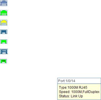
Port Status
UNIT |
Select the unit ID of the desired member in the stack. |
|
Indicates the 1000Mbps port is not connected to a device. |
|
Indicates the 1000Mbps port is at the speed of 1000Mbps. |
|
Indicates the 1000Mbps port is at the speed of 10Mbps or 100Mbps. |
|
Indicates the SFP port is not connected to a device. |
|
Indicates the SFP port is at the speed of 1000Mbps. |
|
Indicates the SFP+ port is not connected to a device. |
|
Indicates the SFP+ port is at the speed of 10000Mbps. |
When the cursor moves on the port, the detailed information of the port will be displayed.
Figure 4-2 Port Information
Port Info
Port: |
Displays the port number of the switch. |
Type: |
Displays the type of the port. |
Rate: |
Displays the maximum transmission rate of the port. |
Status: |
Displays the connection status of the port. |
Click a port to display the bandwidth utilization on this port. The actual rate divided by theoretical maximum rate is the bandwidth utilization. Figure 4-3 displays the bandwidth utilization monitored every four seconds. Monitoring the bandwidth utilization on each port facilitates you to monitor the network traffic and analyze the network abnormities.
15

|
Figure 4-3 Bandwidth Utilization |
Bandwidth Utilization |
|
Rx: |
Select Rx to display the bandwidth utilization of receiving |
|
packets on this port. |
Tx: |
Select Tx to display the bandwidth utilization of sending packets |
|
on this port. |
4.1.2 Device Description
On this page you can configure the description of the switch, including device name, device location and system contact.
Choose the menu System →System Info →Device Description to load the following page.
Figure 4-4 Device Description
The following entries are displayed on this screen:
16

Device Description
Device Name: Enter the name of the switch. Device Location: Enter the location of the switch. System Contact: Enter your contact information.
4.1.3 System Time
System Time is the time displayed while the switch is running. On this page you can configure the system time and the settings here will be used for other time-based functions like ACL.
You can manually set the system time, get UTC automatically if it has connected to an NTP server or synchronize with PC’s clock as the system time.
Choose the menu System →System Info →System Time to load the following page.
Figure 4-5 System Time
The following entries are displayed on this screen:
Time Info
Current System Time: Displays the current date and time of the switch. Current Time Source: Displays the current time source of the switch.
Time Config
Manual: |
When this option is selected, you can set the date and time |
|
manually. |
17

Get Time from NTP Server:
Synchronize with
PC’S Clock:
 Note:
Note:
When this option is selected, you can configure the time zone and the IP Address for the NTP Server. The switch will get UTC automatically if it has connected to an NTP Server.
Time Zone: Select your local time.
Primary/Secondary NTP Server: Enter the IP address for the NTP Server.
Update Rate: Specify the rate fetching time from NTP server.
When this option is selected, the administrator PC’s clock is utilized.
1.The system time will be restored to the default when the switch is restarted and you need to reconfigure the system time of the switch.
2.When Get Time from NTP Server is selected and no time server is configured, the switch will get time from the time server of the Internet if it has connected to the Internet.
4.1.4 License Info
This page displays the status of the license and the features it supports.
Choose the menu System →System Info →License Info to load the following page.
Figure 4-6 License Info
The following entries are displayed on this screen:
License Info |
|
License Copy: |
The information about the number of license. |
18
Loading...