


SLV-LX4
Sony SLV-LX4, SLV-AX20, SLV-LX5, SLV-N60, SLV-LX6S Service Manual
...
SLV-AX10/AX20/N50/N60/N70/N80/
LX4/LX5/LX6S/LX7S/LX8S
RMT-V266A/V266B/V292/V292A/V293/V294
US Model
SLV-AX10/AX20/N50/N60/N70/N80
Canadian Model
SLV-N50/N60/N70/N80
Mexican Model
SLV-LX4/LX5/LX6S(MX)/
LX7S(MX)/LX8S(MX)
Chilean Model
SLV-LX5(CL,CS)/LX7S(CL,CS)/
LX8S(CS)
Panama Model
Venezuelan Model
SLV-LX5(PA,PC,VZ)/LX7S(PA,PC,VZ)
SERVICE MANUAL
VIDEO CASSETTE RECORDER
MICROFILM
S MECHANISM
Refer to the SERVICE MANUAL of VHS
MECHANICAL ADJUSTMENT
for
MECHANICAL ADJUSTMENTS. (9-921-647-11)
System
Format
VHS NTSC standard
Video recording system
Rotary head helical scanning FM system
Video heads
Double azimuth four heads
Video signal
NTSC color, EIA standards
Tape speed
SP: 33.35 mm/s (1
inches/s)
EP: 11.11 mm/s (
inches/s)
LP: 16.67 mm/s (
inches/s),
playback only
Maximum recording/playback time
8 hr
9 hrs. in EP mode (with T-180 tape)
s. in EP mode (with T-160 tape)
Fast-forward and rewind time
Appr
(SLV-AX10/AX20/N50/N60/N70/N80)
(SLV-AX10/AX20/N50/N60/LX4/LX5/LX6S/LX7S)
(SLV-AX10/AX20/N50/N60/N70/N80/LX4(MX)/
LX5(MX,PA,PC,VZ)/LX6S/LX7S(MX,PA,PC,VZ)/
LX8S(MX))
(SLV-AX10/AX20/N50/N60/N70/N80/LX6S/
LX7S/LX8S)
(SLV-AX10/AX20/N50/N60/N70/N80/LX6S/
LX7S/LX8S)
(SLV-LX4/LX5)
(SLV-LX4/LX5/LX6S/LX7S/LX8S)
(SLV-N70/N80/LX8S)
(SLV-N70/N80/LX8S)
(SLV-LX5(CL,CS)/LX7S(CL,CS)/LX8S(CS))
(SLV-AX10/AX20/N50/N60/N70/N80)
ox. 3 min. (with T-120 tape)
Tuner section
Channel coverage
VHF 2 to 13
UHF 14 to 69
CATV A-8 to A-1, A to W, W+1 to W+84
Antenna
75-ohm antenna terminal for VHF/UHF
Inputs and outputs
LINE-1 IN and -2 IN
VIDEO IN, phono jack (1 each)
Input signal: 1 Vp-p, 75 ohms, unbalanced, sync
negative
A
AUDIO IN, phono jack (1 each)
(SLV-LX4/LX5)
AUDIO OUT, phono jack (1)
UDIO IN, phono jacks (2 each)
Input level: 327 mVrms
Input impedance: more than 47 kilohms
LINE OUT
VIDEO OUT, phono jack (1)
Output signal: 1 Vp-p, 75 ohms, unbalanced, sync
negative
AUDIO OUT, phono jacks (2)
Standard output: 327 mVrms
Load impedance: 47 kilohms
Output impedance: less than 10 kilohms
S-LINK (CONTROL S IN) (SLV-N80 only)
Mini jack (1)
CABLE BOX CONTROL (CONTROL S OUT) (SLVN80 only)
Stereo mini jack (plug in power) (1)
Timer section
Clock
Quartz locked
Timer indication
12-hour cycle
Timer setting
8 programs (max.)
Power back-up
Built-in self-charging capacitor
Back-up duration: up to 1 hour at a time
General
Power requirements
12
110 V AC – 240 V AC, 50/60 Hz
0 V AC, 60 Hz
Power consumption
24 W
(SLV-LX4/LX5/LX6S/LX7S/LX8S)
18 W
Operating temperature
5°C to 40°C (41°F to 104°F)
Storage temperature
–20°C to 60°C (–4°F to 140°F)
Dimensions
App
Approx. 355 × 96 × 285 mm (w/h/d)
rox. 430 × 97 × 290.5 mm (w/h/d)
(
(Approx. 14 ×
Approx. 17 × 3 × 11 inches) including
projecting parts and controls
Mass
Approx. 4.1 kg (9 lb 1 oz)
(SLV-AX10/AX20/N50/N60/LX4/LX5/LX6S/LX7S)
Approx. 3.6 kg (7 lb 15 oz)
Supplied accessories
Remote commander (1)
Size AA (R6) batteries (2)
75-ohm coaxial cable with F-type connectors (1)
Audio/video cable (3-phono, 1-mini to 3-phono, 1-mini)
(1) (SLV-N80 only)
Audio/video cable (3-phono to 3-phono) (1) (SLV-N70
only)
Design and specifications are subject to change without
notice.
E
NERGY STAR® is a U.S. registered mark.
As an
E
NERGY STAR® Partner, Sony Corporation has
determined that this product meets the
E
NERGY STAR®
guidelines for energy efficiency.
3
8
7
16
11
16
781
2
3 × 11 inches) including
781
4
SPECIFICATIONS
Photo : SL V -N80
RMT-V292
HiFi model : SLV-AX10/AX20/N50/N60/N70/N80/LX6S/LX7S/LX8S
Mono model: SLV-LX4/LX5
— 2 —
SAFETY CHECK-OUT
After correcting the original service problem, perform the following
safety checks before releasing the set to the customer.
1. Check the area of your repair for unsoldered or poorly-soldered
connections. Check the entire board surface for solder splashes
and bridges.
2. Check the interboard wiring to ensure that no wires are
"pinched" or contact high-wattage resistors.
3. Look for unauthorized replacement parts, particularly
transistors, that were installed during a previous repair . Point
them out to the customer and recommend their replacement.
4. Look for parts which, though functioning, show obvious signs
of deterioration. Point them out to the customer and
recommend their replacement.
5. Check the line cord for cracks and abrasion.
Recommend the replacement of any such line cord to the
customer.
6. Check the B+ voltage to see it is at the values specified.
7. Check the antenna terminals, metal trim, "metallized" knobs,
screws, and all other exposed metal parts for AC leakage.
Check leakage as described below.
LEAKAGE TEST
The AC leakage from any exposed metal part to earth ground and
from all exposed metal parts to any exposed metal part having a
return to chassis, must not exceed 0.5mA (500 microampers).
Leakage current can be measured by any one of three methods.
1. A commercial leakage tester, such as the Simpson 229 or RCA
TW-540A. Follo w the manufacturers' instructions to use these
instruments.
2. A battery-operated A C milliammeter. The Data Precision 245
digital multimeter is suitable for this job.
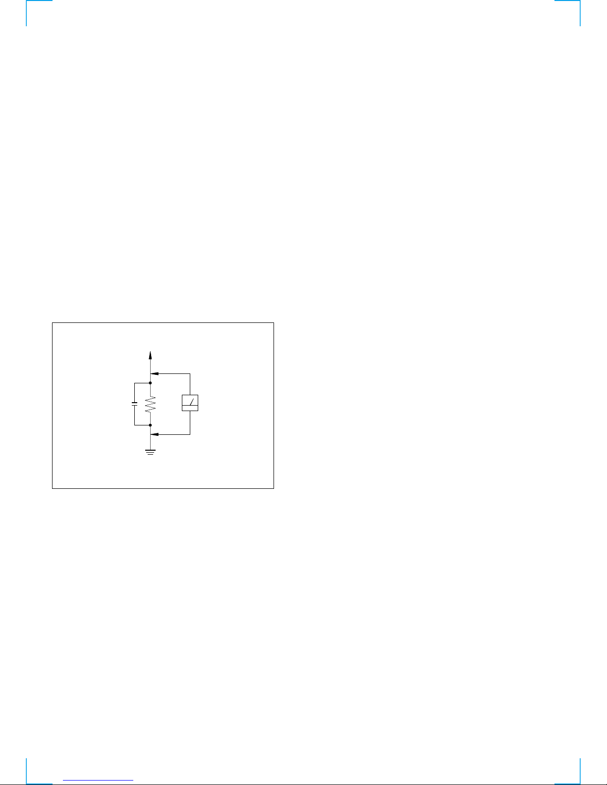
3. Measuring the voltage drop across a resistor by means of a
VOM or battery-operated AC v oltmeter. The "limit" indication
is 0.75V, so analog meters must have an accurate lo w volta ge
scale. The Simpson 250 and Sanwa SH-63Trd are examples
of a passive VOM that is suitable. Nearly all battery operated
digital multimeters that have a 2V A C range are suitable. (See
Fig. A)
T o Exposed Metal
Parts on Set
0.15 µF
1.5 kΩ
AC
Voltmeter
(0.75 V)
Earth Ground
Fig. A. Using an A C v oltmeter to check A C leakage.
SAFETY-RELATED COMPONENT WARNING!!
COMPONENTS IDENTIFIED BY MARK 0 OR DOTTED LINE WITH
MARK 0 ON THE SCHEMATIC DIAGRAMS AND IN THE PARTS
LIST ARE CRITICAL TO SAFE OPERATION. REPLACE THESE
COMPONENTS WITH SONY PARTS WHOSE PART NUMBERS
APPEAR AS SHOWN IN THIS MANUAL OR IN SUPPLEMENTS
PUBLISHED BY SONY .
ATTENTION AU COMPOSANT AYANT RAPPORT
À LA SÉCURITÉ!
LES COMPOSANTS IDENTIFÉS P AR UNE MARQUE 0 SUR LES
DIAGRAMMES SCHÉMA TIQUES ET LA LISTE DES PIÈCES SONT
CRITIQUES POUR LA SÉCURITÉ DE FONCTIONNEMENT. NE
REMPLACER CES COMPOSANTS QUE PAR DES PIÈSES SONY
DONT LES NUMÉROS SONT DONNÉS DANS CE MANUEL OU
DANS LES SUPPÉMENTS PUBLIÉS PAR SONY.

— 3 —
TABLE OF CONTENTS
SERVICE NOTE
1. ERROR CODE INDICATION··········································· 5
1 GENERAL
Getting Started···········································································1-1
Step 1 : Unpacking ································································ 1-1
Step 2 : Setting up the remote commander ····························1-1
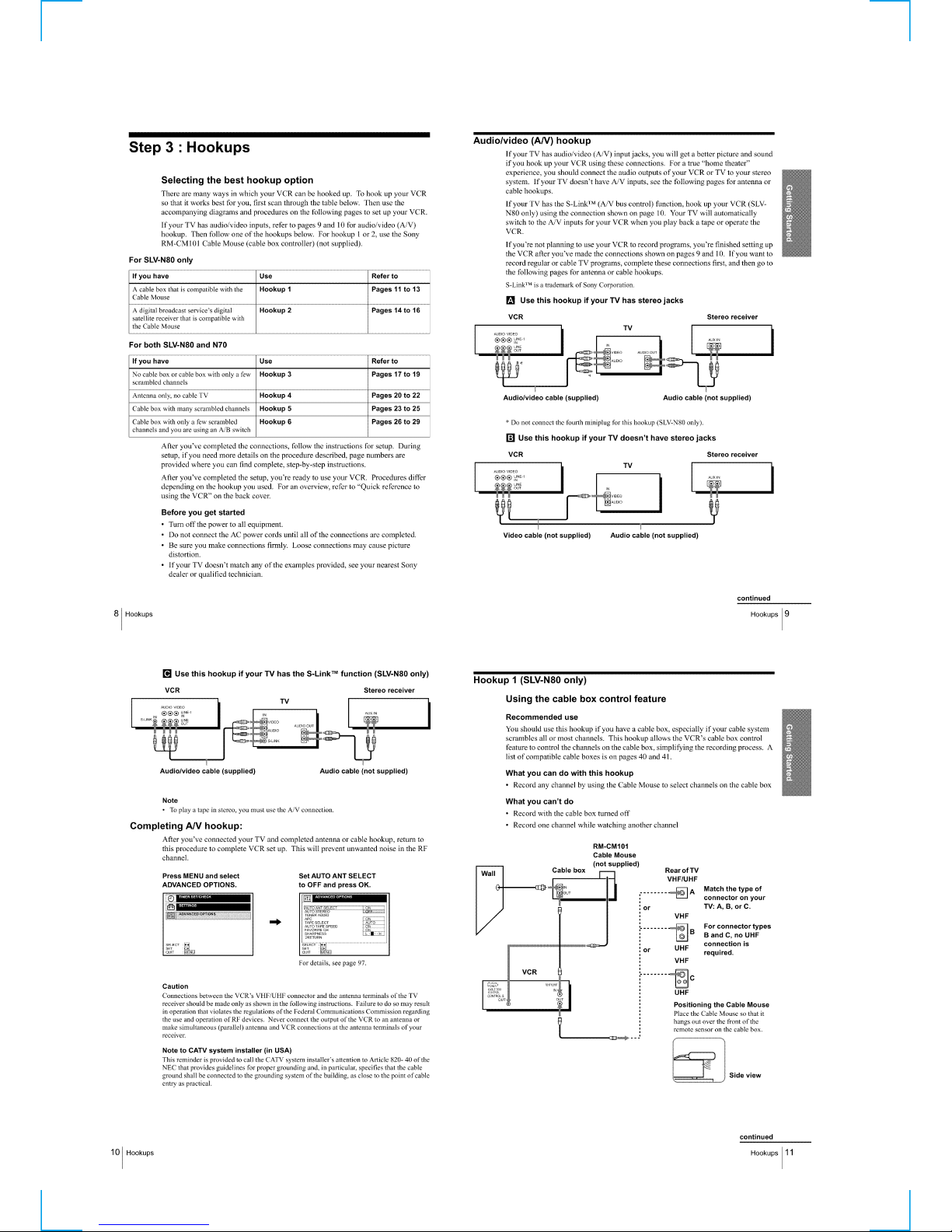
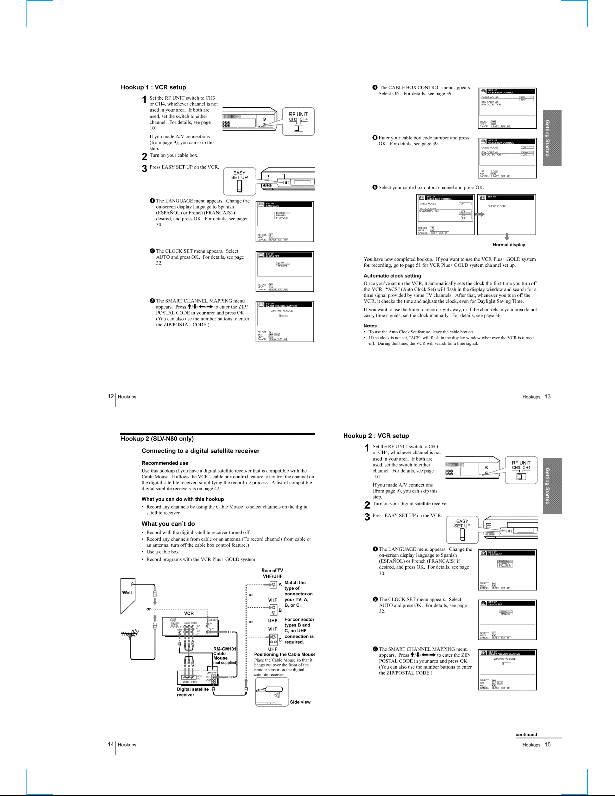
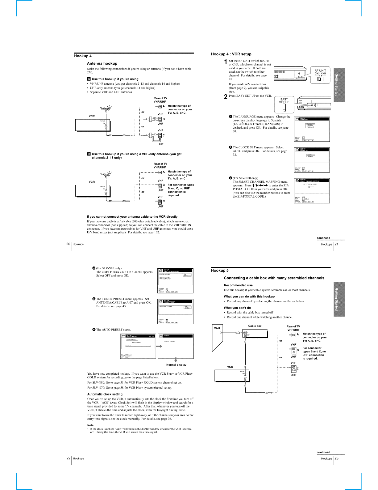
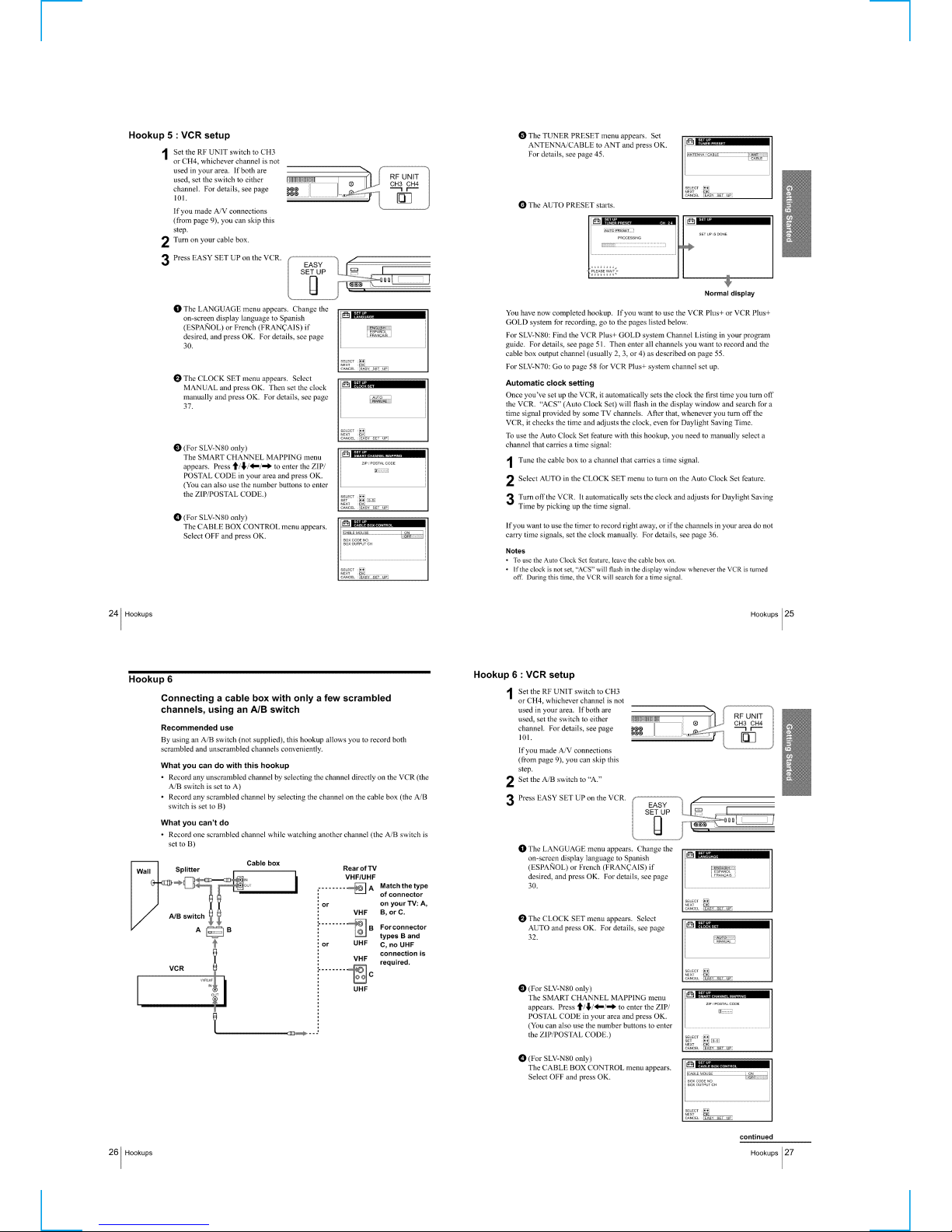
Step 3 : Hookups····································································1-2
Selecting a language ······························································1-7
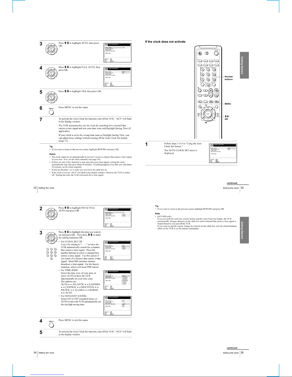
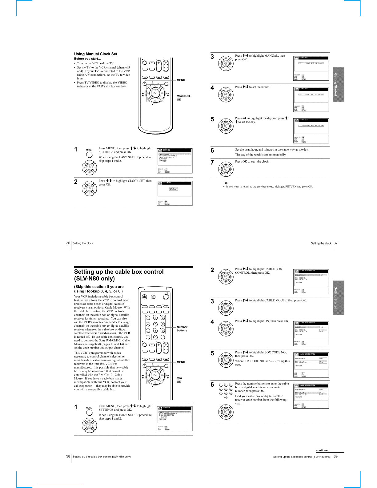
Setting the clock ····································································1-7
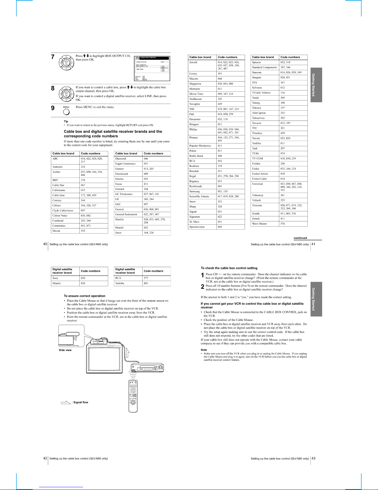
Setting up the cable box control ············································1-9
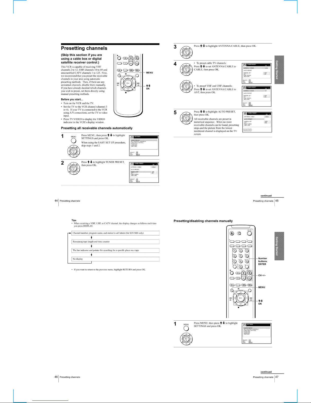
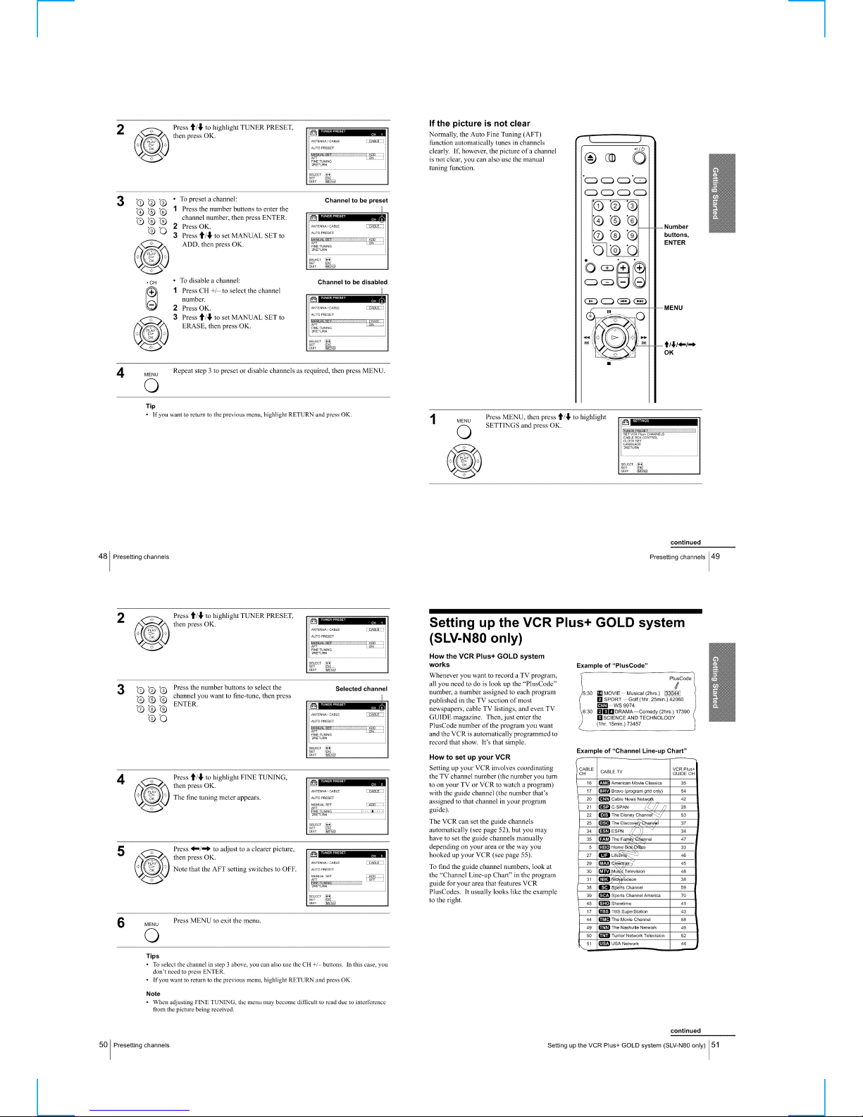
Presetting channels ······························································1-11
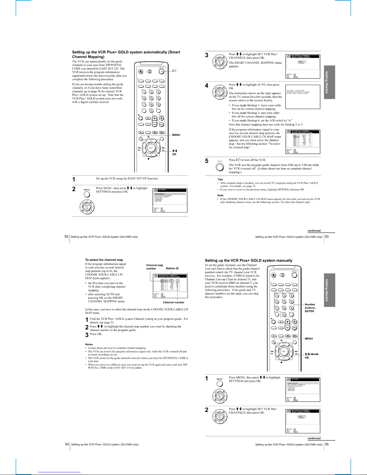
Setting up the VCR Plus+ GOLD system····························1-12
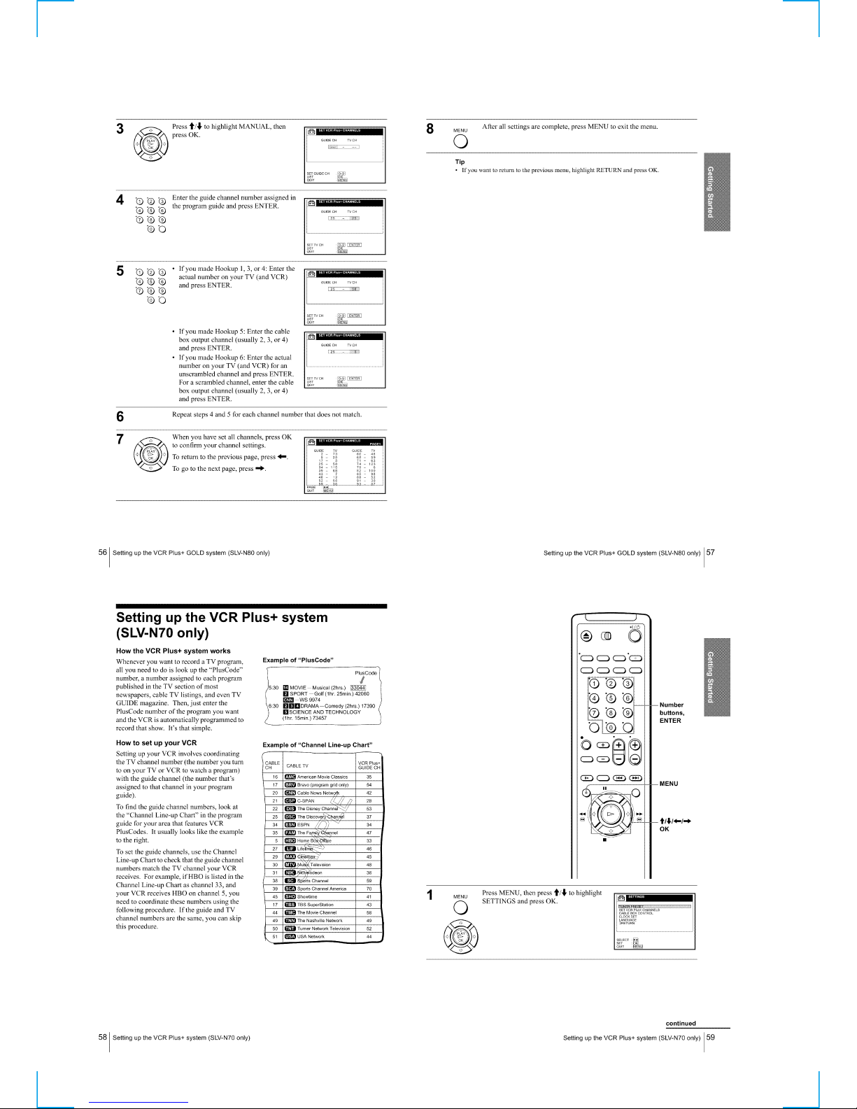
Setting up the VCR Plus+ system········································1-14
Basic Operations······································································1-15
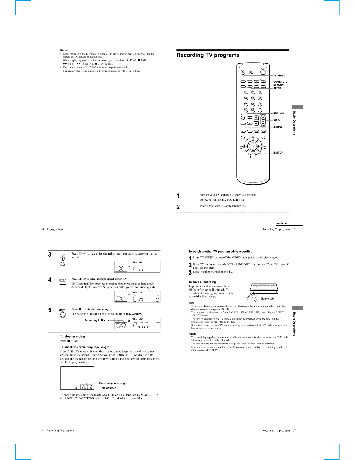
Playing a tape·······································································1-15
Recording TV programs ······················································1-16
Recording TV programs using the Dial Timer ···················· 1-17
Recording TV programs using the VCR Plus+ or
VCR Plus+ GOLD system··················································· 1-18
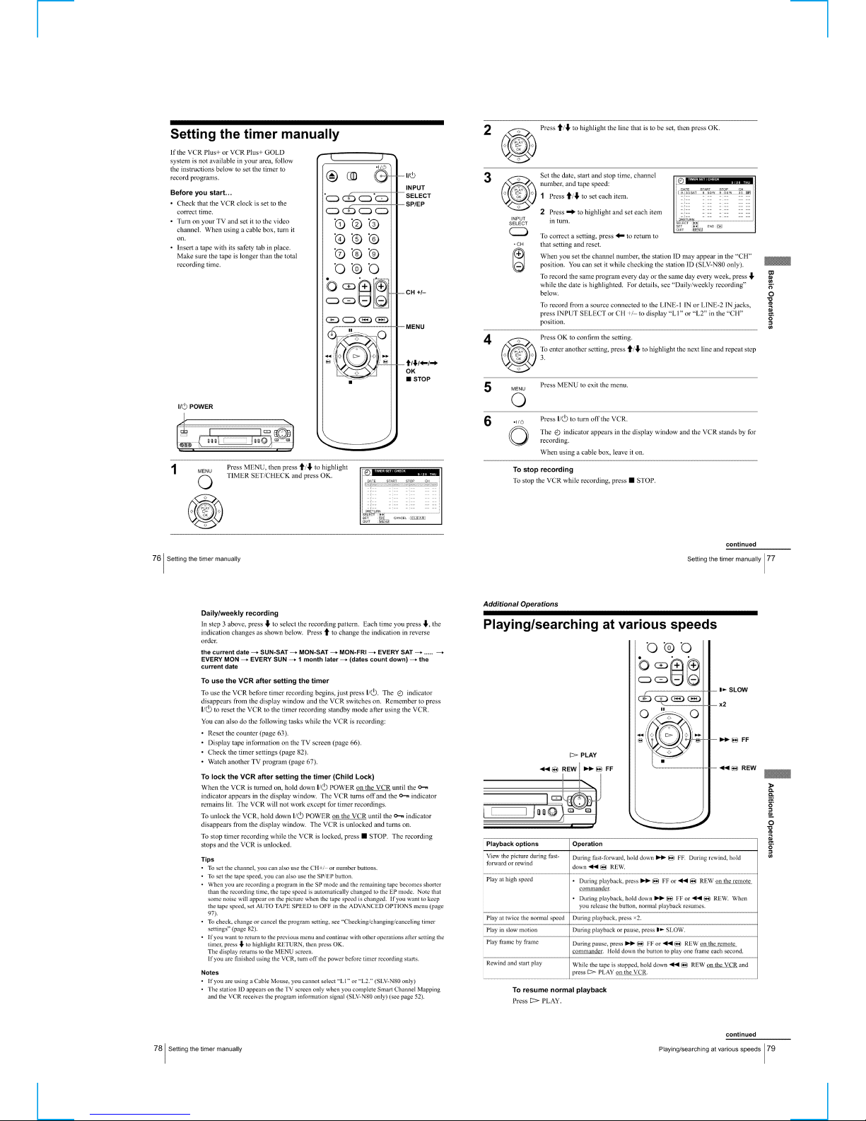
Setting the timer manually··················································· 1-19
Additional Operations ·····························································1-19
Playing/searching at various speeds ····································1-19
Setting the recording duration time ·····································1-20
Checking/changing/canceling timer settings ······················· 1-20
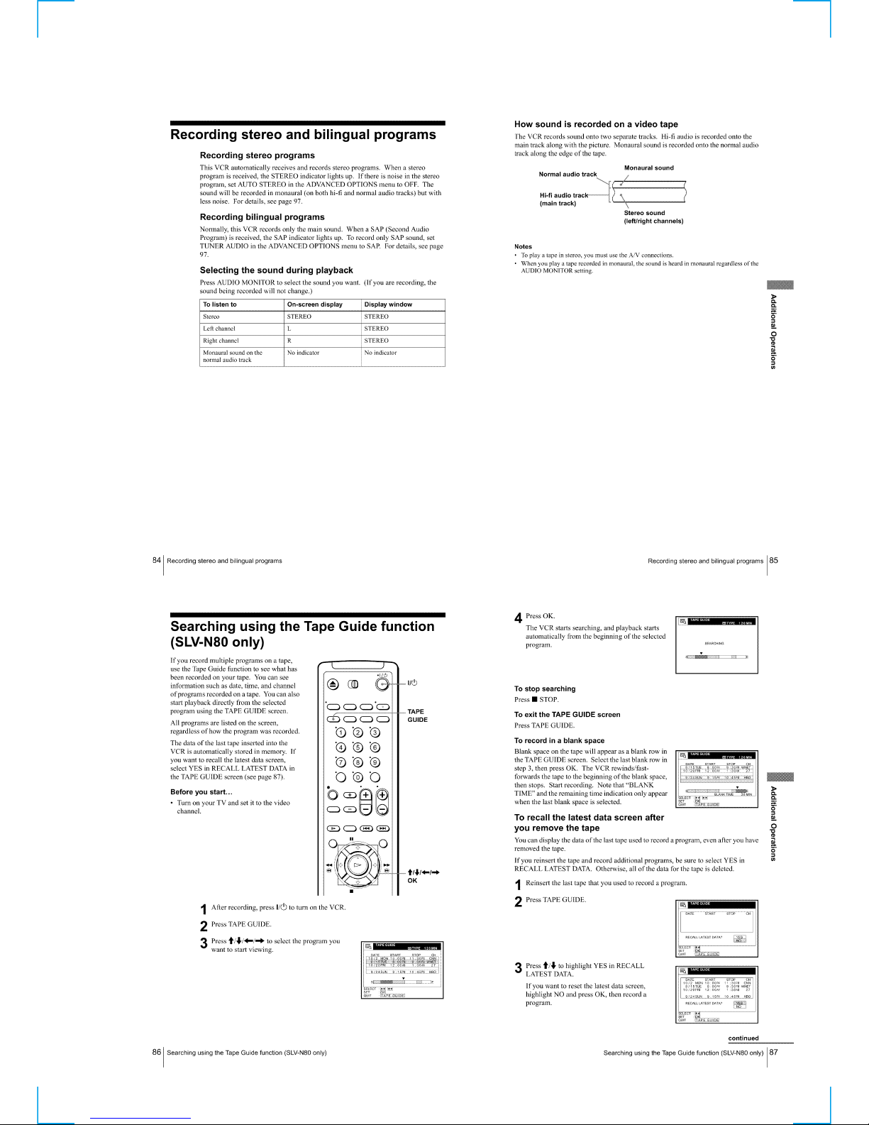
Recording stereo and bilingual programs ····························1-21
Searching using the Tape Guide function ····························1-21
Searching using the index function······································1-22
Searching for a selected point on the tape ···························1-22
Locating a channel by Station ID ········································1-23
Creating a favorite channel list with Station ID ··················1-23
Adjusting the picture ··························································· 1-23
Changing menu options ······················································· 1-24
Editing with another VCR ···················································1-24
Additional Information ····························································1-25
General setup information ···················································1-25
Troubleshooting ···································································1-25
Index to parts and controls···················································1-26
2 DISASSEMBLY
2-1. CASE, FRONT PANEL BLOCK ASSEMBLY ··············2-1
2-2. DM-89 BOARD, DI-74 BOARD, JK-178 BOARD,
MF-319 BOARD ·····························································2-1
2-3. REAR PANEL ·································································2-2
2-4. MA-370 BOARD ····························································2-2
2-5. MECHANISM DECK·····················································2-3
2-6. INTERNAL VIEWS························································2-4
2-7. CIRCUIT BOARDS LOCATION ···································2-5
3 BLOCK DIAGRAMS
3-1. OVERALL BLOCK DIAGRAM ····································3-1
3-2. VIDEO BLOCK DIAGRAM ··········································3-3
3-3. SERVO/SYSTEM CONTROL BLOCK DIAGRAM ·····3-5
3-4. TUNER BLOCK DIAGRAM ········································· 3-7
3-5. AUDIO BLOCK DIAGRAM ··········································3-9
3-6. POWER BLOCK DIAGRAM······································· 3-11
4 PRINTED WIRING BOARDS AND
SCHEMATIC DIAGRAMS
4-1. FRAME SCHEMATIC DIAGRAM································4-3
4-2. PRINTED WIRING BOARDS AND SCHEMATIC
DIAGRAMS····································································4-5
• MA-370 (VIDEO, AUDIO, SERVO/SYSTEM
CONTROL, TUNER, POWER)
PRINTED WIRING BOARD ························· 4-5
• MA-370 (1/8)(REC/PB HEAD AMP)
SCHEMATIC DIAGRAM ······························4-7
• MA-370 (2/8)(Y/C, AUDIO PROCESS)
SCHEMATIC DIAGRAM ······························4-9
• MA-370 (3/8)(SERVO/SYSTEM CONTROL)
SCHEMATIC DIAGRAM ····························4-11
• MA-370 (4/8)(AUDIO PROCESS)
SCHEMATIC DIAGRAM ····························4-13
• MA-370 (5/8)(TUNER)
SCHEMATIC DIAGRAM ····························4-15
• MA-370 (6/8)(DISPLAY CONTROL)
SCHEMATIC DIAGRAM ····························4-17
• MA-370 (7/8)(POWER SUPPLY)
SCHEMATIC DIAGRAM ····························4-19
• MA-370 (8/8)(VSET)
SCHEMATIC DIAGRAM ····························4-21
• JK-178 (LINE-2 IN)
PRINTED WIRING BOARD AND
SCHEMATIC DIAGRAM
(AX10/AX20/N50/N60/LX4/LX5/
LX6S/LX7S) ················································ 4-29
• JK-191 (LINE-2 IN)
PRINTED WIRING BOARD AND
SCHEMATIC DIAGRAM
(N70/N80/LX8S only) ··································4-31
• DM-89 (FUNCTION)
PRINTED WIRING BOARD AND
SCHEMATIC DIAGRAM
(N70/N80/LX8S only) ··································4-33
• MF-319 (SIRCS)
PRINTED WIRING BOARD AND
SCHEMATIC DIAGRAM
(N70/N80/LX8S only) ··································4-35
• DI-74 (DIAL TIMER)
PRINTED WIRING BOARD AND
SCHEMATIC DIAGRAM
(EXCEPT: AX10/N50) ·································4-36
5 INTERFACE, IC PIN FUNCTION
DESCRIPTION
5-1. SYSTEM CONTROL — MECHANISM BLOCK
INTERFACE (MA-370 BOARD IC160) ························ 5-1
5-2. SYSTEM CONTROL — SERVO PERIPHERAL
CIRCUIT INTERFACE (MA-370 BOARD IC160) ······· 5-1
5-3. SYSTEM CONTROL — SYSTEM CONTROL
PERIPHERAL CIRCUIT INTERFACE
(MA-370 BOARD IC160)···············································5-2
5-4. SYSTEM CONTROL AND RF MODULATOR
— INPUT SELECTION BLOCK INTERFACE
(MA-370 BOARD IC160)···············································5-2
5-5. SYSTEM CONTROL — VIDEO/RP BLOCK
INTERFACE (MA-370 BOARD IC160) ························5-2
5-6. SYSTEM CONTROL — AUDIO BLOCK INTERFACE
(MA-370 BOARD IC160)···············································5-2
5-7. SERVO/SYSTEM CONTROL MICROPROCESSOR
PIN FUNCTIONS (MA-370 BOARD IC160)················5-3
6 ADJUSTMENTS
6-1 MECHANICAL ADJUSTMENTS ·································6-1
6-2. ELECTRICAL ADJUSTMENTS ···································6-1
2-1. PREPARATION BEFORE ADJUSTMENT ···················6-1
2-1-1.Equipment Required ························································6-1
2-1-2.Equipment Connection ····················································6-1
2-1-3.Set-up of Adjustment·······················································6-1
2-1-4.Alignment Tape ······························································· 6-1
2-1-5.Input/Output Levels and Impedance ·······························6-2
2-1-6.Adjustment Sequence ······················································6-2
2-2. POWER SUPPLY CHECK ·············································6-2
2-2-1.Output Voltage Check (MA-370 Board) ·························6-2

— 4 —
2-3. SERVO SYSTEM CHECK ············································· 6-3
2-3-1.RF Switching Position Adjustment (MA-370 Board) ·····6-3
2-4. AUDIO SYSTEM ADJUSTMENT·································6-3
2-4-1.Hi-Fi Audio System Adjustment (Hi-Fi model only) ······6-3
2-4-2.HiFi Switching Position Adjustment (MA-370 Board)···6-4
2-4-3.Normal Audio System Adjustment ·································· 6-4
2-4-4.ACE Head Adjustment ····················································6-4
2-4-5.E-E Output Level Check ·················································6-4
2-4-6.Frequency Response Check·············································6-4
2-5. ADJUSTING PARTS LOCATION DIAGRAM ·············6-6
7 REPAIR PARTS LIST
7-1. EXPLODED VIEWS ······················································ 7-1
7-1-1.FRONT PANEL AND UPPER CASE SECTION ··········7-1
7-1-2.CHASSIS SECTION······················································· 7-2
7-1-3.MECHANISM DECK SECTION-1 ······························· 7-3
7-1-4.MECHANISM DECK SECTION-2 ······························· 7-4
7-1-5.MECHANISM DECK SECTION-3 ······························· 7-5
7-2. ELECTRICAL PARTS LIST ··········································7-6
— 5 —
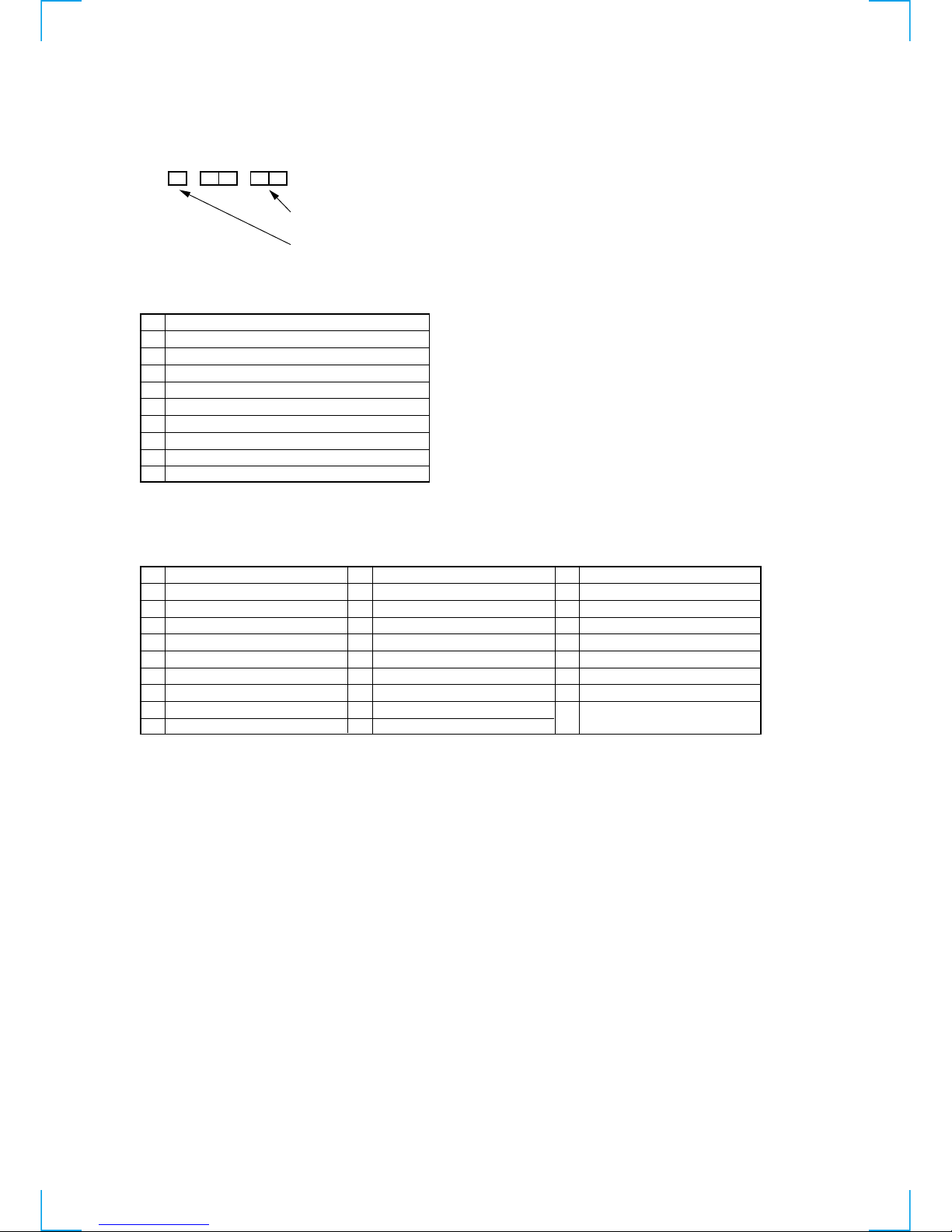
1. ERROR CODE INDICATION
• Error codes are indicated using the lower 5 digits in the fluorescent display tube.
“At this time, Colon “:” between character is not indicated.”
ERROR CODE
MODE CODE
0 Power-on eject 10 FWD x1 20 REW play
1 Power-on initial 11 FWD x2 21 Cas. loading
2 Power-off eject 12 CUE 22 Tape loading
3 Power-off stop 13 PB-pause 23 Power-off loading
4 FF 14 RVS-pause 24 Mecha. error (Power on)
5 REW 15 RVS x1 25 Power-on eject initial
6 REC 16 RVS x2 26 Power-off eject initial
7 REC- pause 17 REV 27 APC REC
8 Power-on stop 18 Power-off initial 28 Cas. loading
9 PB 19 Mecha. error (Power off) (No auto PB check)
0 No error
1 Cam encoder error Loading direction
2 Cam encoder error Unloading direction
3 T reel error
4 S reel error
5 Capstan error
6 Drum error
7 Error on initializing
8 Cassette loading error
9 Reserve
SERVICE NOTE
Mode code indication when the error has occurred.
Error code

— 6 —
MEMO

1-1
SECTION 1
GENERAL
This section is extracted from instruction
manual. (SLV-N70/N80 model)
SLV-AX10/AX20/N50/N60/N70/N80/
LX4/LX5/LX6S/LX7S/LX8S
1-2
1-3

1-4
1-5
1-6

1-7
1-8
1-9
1-10
1-11
1-12
1-13
1-14

1-15
1-16

1-17

1-18
1-19

1-20
1-21

1-22

1-23
 Loading...