


SLV-L45AR/L65HFAR/L75HFAR
RMT-V241/V242V
SERVICE MANUAL
Argentina Model
Ver 1.0 1998.07
Photo : SLV-L75HFAR
SPECIFICATIONS
Sistema
Formato
VHS PAL-N/NTSC estándar Cobertura de canales
VHF 2 a 13 UHF 14 a 69
CATV A-8 a A-1, A a W, W+1 a W+84
Antena
Terminal de antena de 75 ohmios para VHF/UHF
Entradas/salidas
LINE IN (SLV-L65HFAR)
LINE IN y LINE IN 2 (SLV-L45AR/L75HFAR) VIDEO IN
Toma fonográfica (1) (S LV-L65HFAR)
Tomas fonográficas (1 por cada) (S LV-L45AR/L75HFAR) Señal de entrada : 1 Vp-p, 75 ohmios,
desequilibrada, sincronización negativa AUDIO IN
Tomas fonográficas (2, L/R) (S LV-L65HFAR) Tomas fonográficas (1 por cada) (S LV-L45AR)
Tomas fonográficas (2 por cada, L/R) (S LV-L75HFAR) Nivel de entrada : 327 m Vrms,
Impedancia de entrada : superior a 47 kiloohmios
LINE OUT VIDEO OUT
Toma fonográfica (1)
Señal de Salida : 1 Vp-p, 75 ohmios, desequilibrada, sincronización negativa AUDIO OUT
Tomas fonográficas (2, L/R) (S LV-L65HFAR/L75HFAR) Toma fonográfica (1) (S LV-L45AR)
Salida estándar : 327 m Vrms, Impedancia de carga : 47 kiloohmios Impedancia de salida : inferior a
10 kiloohmios
General
Requisitos de alimentación 220 a 240 V CA, 50Hz
Consumo de energía 18 W
Temperatura de funcionamiento 5˚C a 40˚C
Temperatura de almacenamiento -20˚C a 60˚C
Dimensiones
Aprox. 360 x 97 x 298 mm (an /al / fn) incluidas las piezas y controles sobresalientes
Masa
Aprox. 3,7 kg
Accesorios suministrados
Control remoto (1)
Pilas tipo R6 (tamañ o AA) (2) Cable de antena (1)
Cable de audio / video (1)
(sólo el modelo S LV-L65HFAR/L75HFAR) Cable de alimentación de CA (1)
Diseño y especificaciones sujetos a modificaciones sin previo aviso.
JVIDEO CASSETTE RECORDER
N-PAL NTSC
MICROFILM
SAFETY CHECK-OUT
After correcting the original service problem, perform the following safety check before releasing the set to the customer :
1.Check the area of your repair for unsoldered or poorly-sol- dered connections. Check the entire board surface for solder splashes and bridges.
2.Check the interboard wiring to ensure that no wires are “pinched” or contact high-wattage resistors.
3.Look for unauthorized replacement parts, particularly transistors, that were installed during a previous repair. Point them out to the customer and recommend their replacement.
4.Look for parts which, though functioning, show obvious signs of deterioration. Point them out to the customer and recommend their replacement.
5.Check the B+ voltage to see it is at the values specified.
SAFETY-RELATED COMPONENT WARNING!!
COMPONENTS IDENTIFIED BY MARK ! OR DOTTED LINE WITH MARK !ON THE SCHEMATIC DIAGRAMS AND
IN THE PARTS LIST ARE CRITICAL TO SAFE OPERATION. REPLACE THESE COMPONENTS WITH SONY PARTS WHOSE PART NUMBERS APPEAR AS SHOWN IN THIS MANUAL OR IN SUPPLEMENTS PUBLISHED BY SONY.
ATTENTION AU COMPOSANT AYANT RAPPORT
À LA SÈCURITÉ!
LES COMPOSANTS IDENTIFIÉS PAR UNE MARQUE !SUR
LES DIAGRAMMES SCHÉMATIQUES ET LA LISTEDES PIÉCES SONT CRITIQUES POUR LA SÉCURITÉ DE FONCTIONNEMENT.
NE REMPLACER CES COMPOSANTS QUE PAR DES PIÉCES SONY DONT LES
NUMÉROS SONT DONNÉS DANS CE MANUEL OUDANS LES SUPPLÉMENTS PUBLIÉS PAR SONY.
– 2 –
TABLE OF CONTENTS
Section |
Title |
Page |
Section |
Title |
Page |
______ |
____ |
____ |
______ |
____ |
____ |
1. GENERAL |
|
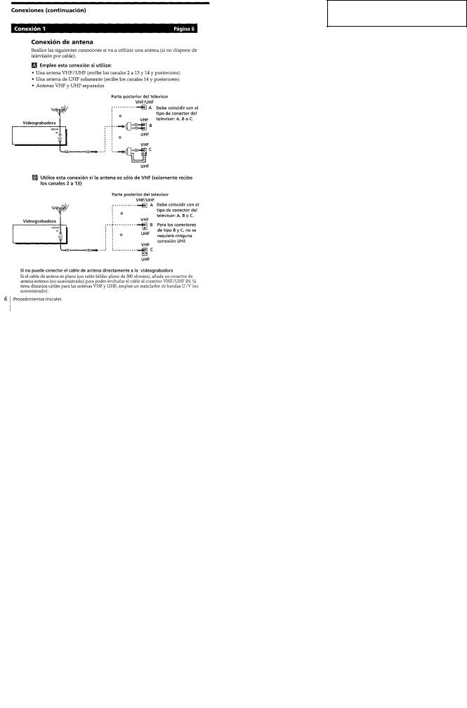
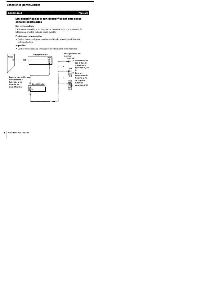
Paso 1 Conexiones ........................................................ |
1-1 |
Paso 2 Configuración de la videograbador a .................. |
1-2 |
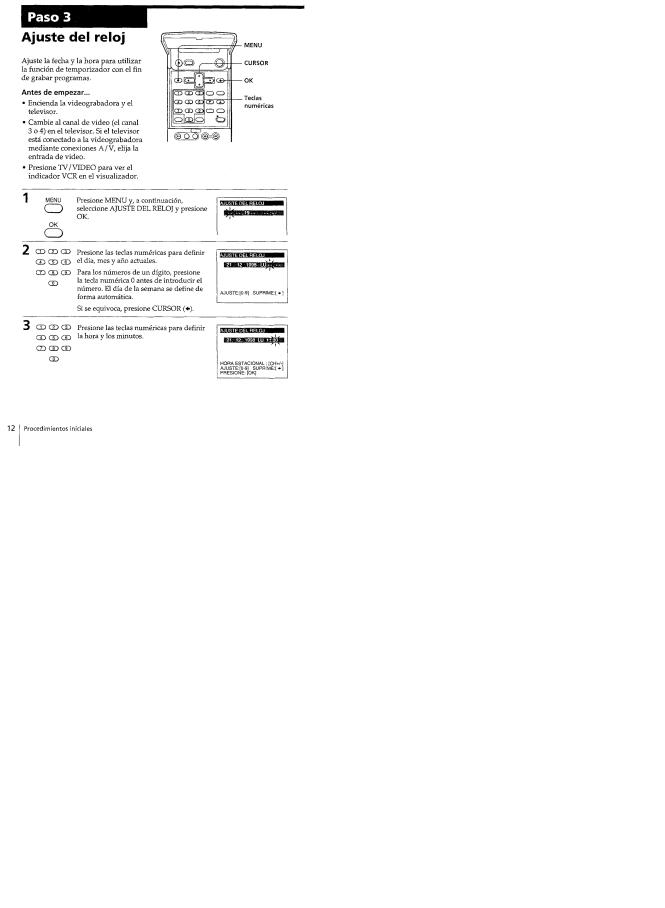
Paso 3 Ajuste del reloj ................................................... |
1-3 |
Selección del idiom a ..................................................... |
1-3 |
Instrucciones adicionales de sintonizació n ................... |
1-3 |
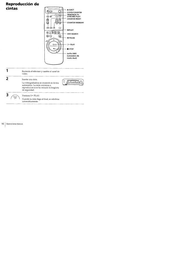
Reproducción de cinta s ................................................. |
1-4 |
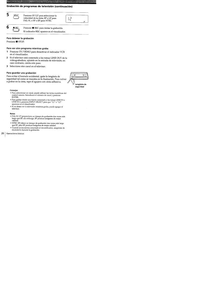
Grabación de programas de televisió n .......................... |
1-4 |
Grabación de programas de televisión con |
|
temporizador ................................................................. |
1-5 |
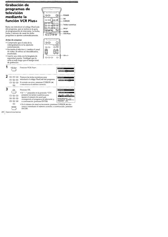
Grabación de programas de televisión mediante la |
|
funció n VCR Plus + ...................................................... |
1-6 |
Reproducción/búsqueda a distintas velocidade s ........... |
1-6 |
Grabación de programas de televisión con el |
|
temporizador instantáne o .............................................. |
1-6 |
Comprobación/cancelación de ajustes del |
|
temporizador ................................................................. |
1-7 |
Búsquedas con la función de índic e .............................. |
1-7 |
Grabación de programas estéreo y bilingüe s ................ |
1-7 |
Edición con otra videograbador a .................................. |
1-7 |
Ajuste de la imagen ....................................................... |
1-8E |
Indice visual .................................................................. |
1-8E |
2. DISASSEMBLY |
|
1-1. Removal of Cabinet, Mechanism Unit and Main |
|
Board ..................................................................... |
2-1 |
Removing the Cabinet Parts .................................. |
2-1 |
Removing the Mechanism Main Unit and the |
|
CP-1 PWB Assembly ............................................. |
2-1 |
l-2. Temporarily Setting Up and Connecting |
|
CP-1 PWB Assembly ............................................. |
2-3E |
1-3. Installation of the Front Panel ................................ |
2-3E |
3. DIAGRAMS |
|
Circuit Boards Location ................................................ |
3-1 |
Mechanism Connection Diagram .................................. |
3-2 |
Overall wiring Diagram (SLV-L45AR) ......................... |
3-3 |
Overall wiring Diagram (SLV-L65HFAR/L75HFAR) ... |
3-5 |
System Control & Servo Circuit Diagram |
|
(SLV-L45AR) ................................................................ |
3-7 |
System Control & Servo Circuit Diagram |
|
(SLV-L65HFAR/L75HFAR) ......................................... |
3-9 |
Audio & Video Circuit Diagram (SLV-L45AR) ........... |
3-11 |
Video & Audio Circuit Diagram |
|
(SLV-L65HFAR/L75HFAR) ......................................... |
3-13 |
4.SCHEMATIC DIAGRAMS AND PRINTED WIRING BOARDS
CP-1 Board (PW-A) Power Supply Circuit Diagram ... |
4-1 |
CP-1 Board (VA-A) Video, Audio & Tuner |
|
Circuit Diagram (SLV-L45AR) ..................................... |
4-3 |
CP-1 Board (VA-A) Video, Audio & Tuner |
|
Circuit Diagram (SLV-L65HFAR/L75HFAR) .............. |
4-5 |
Video Circuit Waveforms .............................................. |
4-7 |
VP-1 Board Video Pre-Amp circuit Diagram |
|
(SLV-L45AR) ................................................................ |
4-8 |
VP-1 Board Video Pre-Amp circuit Diagram |
|
(SLV-L65HFAR/L75HFAR) ......................................... |
4-9 |
A7101 Display (FLD) Grid/Anode Assignment |
|
Drawing & Table ........................................................... |
4-11 |
TM-1, 2 Boards Operation Key, Display & Timer |
|
Circuit Diagram (SLV-L45AR) ..................................... |
4-11 |
TM-1, 2 Boards Operation Key, Display & Timer |
|
Circuit Diagram (SLV-L65HFAR/L75HFAR) .............. |
4-13 |
Servo Circuit Waveforms .............................................. |
4-15 |
IC 301 System Control & Tuning Control MPU Pin |
|
Functions Table ............................................................. |
4-16 |
CP-1 Board (SY-A) System Control & Servo |
|
Circuit Diagram (SLV-L45AR) ..................................... |
4-17 |
CP-1 Board (SY-A) System Control & Servo |
|
Circuit Diagram (SLV-L65HFAR/L75HFAR) .............. |
4-19 |
5. ADJUSTMENTS |
|
1. Maintaining and Checking the Mechanism ............... |
5-1 |
l -1. Regular Checks and Maintenance Items ............... |
5-1 |
1-1-1. Regular Checks ................................................ |
5-1 |
1-1-2. Cleaning ............................................................ |
5-1 |
1-2 Service Tools ........................................................... |
5-2 |
1-2-1. Service Tools ................................................... |
5-2 |
1-2-2. Using the Relay Cable (J-6090-057-A) ............ |
5-3 |
2. An Overview of the Mechanism ................................ |
5-3 |
2-1. Names of the Main Parts ........................................ |
5-3 |
2-1-1. Cassette Mechanism Assembly ........................ |
5-3 |
2-1-2. Top View .......................................................... |
5-4 |
2-1-3. Under Side ........................................................ |
5-4 |
2-2. An Overview of the Mechanism Modes ................ |
5-5 |
2-2-1. Mechanism Mode Switching Table .................. |
5-5 |
2-2-2. Movement Check List for the Main Parts of the |
|
Mechanism ........................................................ |
5-6 |
2-2-3. How to Check the Mechanism |
|
Mode Position ................................................... |
5-6 |
2-2-4. Self-Diagnosis Display ..................................... |
5-6 |
3. Disassembling the Main Parts of the Mechanism ..... |
5-7 |
3-1. How to Make the Mechanism Move ...................... |
5-7 |
3-1-1. How to Operate the Loading Motor Using |
|
A DC Voltage Supply ....................................... |
5-7 |
3-1-2. Operating the Loading Motor |
|
by the Manual Method ...................................... |
5-7 |
3-1-3. Making the Mechanism Move |
|
Using the Manual Method ................................ |
5-7 |
3-2. Mechanism Unit ..................................................... |
5-8 |
3-3. Cassette Drive Mechanism .................................... |
5-8 |
3-3-1. Cassette Mechanism Assembly ........................ |
5-8 |
3-3-2. Cassette Drive Gear .......................................... |
5-9 |
3-3-3. Door opener, Under Frame and Stand L ........... |
5-9 |
3-3-4. Start Rack Gear and Front Rack Gear .............. |
5-10 |
3-4. Cleaner Roller Assembly ....................................... |
5-10 |
3-5. Cylinder (DRUM) .................................................. |
5-11 |
3-5-1. Cylinder Motor (ROTOR and STATOR) ......... |
5-11 |
3-5-2. Cylinder Assembly ........................................... |
5-11 |
3-6. FE Head and ACE Head ........................................ |
5-12 |
3-6-1. Audio R/P Head Assembly (ACE HEAD) ....... |
5-12 |
3-6-2. Full Erase Head ................................................ |
5-12 |
3-7. Capstan Motor ........................................................ |
5-13 |
3-7-1. Capstan Motor .................................................. |
5-13 |
3-7-2. Capstan Brake Assembly .................................. |
5-13 |
3-8. Loading Motor Assembly and |
|
Worm Gear Assembly ............................................ |
5-14 |
3-9. Pinch Roller Pressure Mechanism ......................... |
5-14 |
3-9-1. Pinch Roller Lever Assembly ........................... |
5-14 |
3-9-2. Pinch Lift Cam and Pinch Cam Gear ............... |
5-15 |
3-10. L Guide Lever Assembly and |
|
Load Lever Assembly .......................................... |
5-16 |
3-11. BT Lever Assembly ............................................. |
5-16 |
3-12. Reel Drive Mechanism ........................................ |
5-17 |
3-12-1. Reel Belt, Reel Pulley, Friction Gear |
|
Assembly and Clutch Change Lever .............. |
5-17 |
3-12-2. Clutch Mounting Assembly ............................ |
5-17 |
– 3 –
Section |
Title |
Page |
Section |
Title |
Page |
______ |
____ |
____ |
______ |
____ |
____ |
3-12-3. S Soft Lever, Supply Reel Assembly |
|
2-4-3. RF AGC Adjustment ........................................ |
6-10E |
||
and S Reel Gear .............................................. |
|
5-17 |
3. Test Points for Tape Path Adjustment ....................... |
6-10E |
|
3-12-4. T Soft Brake Assembly, Take Up Reel |
|
|
|
|
|
Assembly, T Reel Gear ................................... |
5-18 |
7. EXPLODED VIEWS |
|
|
|
3-13. Brakes .................................................................. |
|
5-18 |
7-1. Cabinet & Chassis Parts ......................................... |
7-1 |
|
3-13-1. S Brake Assembly, T Brake |
|
7-2. Mechanism Parts-1 |
................................................ |
7-2 |
|
Assembly, T Brake ACT Slide ........................ |
5-18 |
7-3. Mechanism Parts-2 ................................................ |
|
7-4E |
|
3-13-2. Brake Control Lever and Brake ACT Lever |
|
|
|
|
|
Assembly ........................................................ |
|
5-19 |
8. ELECTRICAL PARTS .................................LIST |
8-1 |
|
3-13-3. S Brake ACT Slide and BT Spring Lever |
|
Hardware List ................................................................ |
|
8-9E |
|
Assembly ........................................................ |
|
5-19 |
|
|
|
3-14. Guides .................................................................. |
|
5-20 |
|
|
|
3-14-1. Guide Roller Assembly ................................... |
5-20 |
|
|
|
|
3-14-2. S and T Incline Mounting Assemblies ............ |
5-20 |
|
|
|
|
3-15. Wheel Gear 2, Main Cam and Mode Switch ....... |
5-21 |
|
|
|
|
3-16. Crescent Slide ...................................................... |
|
5-22 |
|
|
|
3-17. S Load Gear, T Load Gear, S Load Lever |
|
|
|
|
|
Assembly and T Load Lever Assembly ............... |
5-23 |
|
|
|
|
3-18. Tape Sensors, Reel Sensor and EP SW Lever ..... |
5-24 |
|
|
|
|
3-18-1. Tape Top Sensor and Tape End Sensor ........... |
5-24 |
|
|
|
|
3-18-2. Reel Sensor ..................................................... |
|
5-24 |
|
|
|
3-18-3. EP Switch Lever ............................................. |
|
5-24 |
|
|
|
4. Mechanism Checks and Adjustments ........................ |
5-25 |
|
|
|
|
4-1. Reel Table Torque Check ....................................... |
5-25 |
|
|
|
|
4-2. Adjusting the BT Lever Assembly Position and |
|
|
|
|
|
Checking the Back Tension Torque in Play Mode ..... |
5-25 |
|
|
|
|
4-2-1. BT Lever Pole Position Adjustment ................. |
5-25 |
|
|
|
|
4-2-2. Checking the Back Tension Torque |
|
|
|
|
|
Play Mode ......................................................... |
|
5-25 |
|
|
|
4-3. Tape Path Adjustment |
............................................ |
5-26 |
|
|
|
4-3-1. Adjustment Procedure ...................................... |
5-26 |
|
|
|
|
4-3-2. Load Lever Assembly Height Adjustment ....... |
5-26 |
|
|
|
|
4-3-3. Guide Roller Height Adjustment ...................... |
5-27 |
|
|
|
|
4-3-4. Audio R/P Head (ACE HEAD) Height |
|
|
|
|
|
Adjustment, Azimuth Adjustment and |
|
|
|
|
|
Horizontal Position Adjustment ........................ |
5-28 |
|
|
|
|
4-3-5. Checking After Adjustment .............................. |
5-29E |
|
|
|
|
6. ELECTRICAL ADJUSTMENTS |
|
|
|
|
|
Circuit Boards Location ................................................ |
|
6-1 |
|
|
|
Self -Diagnosis Display ................................................. |
|
6-2 |
|
|
|
1. Self-Diagnosis Contents and Mechanism Mode |
|
|
|
|
|
Display ...................................................................... |
|
6-2 |
|
|
|
2. Electrical Adjustment ................................................ |
|
6-4 |
|
|
|
2-1. Servo Circuit Adjustment ....................................... |
6-4 |
|
|
|
|
2-1-1. Test Equipment and Standards Required .......... |
6-4 |
|
|
|
|
2-1-2. Location of Adjustment Points ......................... |
6-4 |
|
|
|
|
2-1-3. Switching Position Adjustment ........................ |
6-5 |
|
|
|
|
2-1-4. SP STIL V-LOCK Adjustment ......................... |
6-5 |
|
|
|
|
2-2. Video Circuit Relay Jig .......................................... |
6-6 |
|
|
|
|
2-2-1. Test Equipment and Standards Required .......... |
6-6 |
|
|
|
|
2-3. MTS Decoder Circuit Adjustment |
|
|
|
|
|
(SLV-L65HFAR/L75HFAR only) .......................... |
6-7 |
|
|
|
|
2-3-1. Test Equipment and Standards Required .......... |
6-7 |
|
|
|
|
2-3-2. Location of Adjustment Points ......................... |
6-7 |
|
|
|
|
2-3-3. Stereo/SAP Filter Adjustment .......................... |
6-8 |
|
|
|
|
2-3-4. Stereo VCO Adjustment ................................... |
6-8 |
|
|
|
|
2-3-5. Input Level Adjustment .................................... |
6-8 |
|
|
|
|
2-3-6. Separation Adjustment ...................................... |
6-8 |
|
|
|
|
2-3-7. Audio Output Mode and Output Signal Check ... |
6-9 |
|
|
|
|
2-4. IF Circuit Adjustment |
............................................ |
6-10E |
|
|
|
2-4-1. Test Equipment and Standard Required ........... |
6-10E |
|
|
|
|
2-4-2. Location of Adjustment Point ........................... |
6-10E |
|
|
|
|
– 4 –
SLV-L45AR/L65HFAR/L75HFAR
SECTION 1
GENERAL
This section is extracted from SLVL75HFAR instruction manual.
1-1
1-2
1-3
1-4
1-5
1-6
1-7

1-8 E
SLV-L45AR/L65HFAR/L75HFAR
SECTION 2
DISASSEMBLY
1-1. REMOVAL OF CABINET, MECHANISM UNIT AND MAIN BOARD
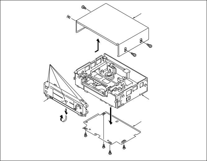
REMOVING THE CABINET PARTS (Fig. 1-1-1 )
1.Remove the cabinet and bottom cover by removing the four screws 1 and four screws 2 .
2.Remove the front panel by removing the locks of the clamps (A) using a screwdriver, etc. and slightly rotating the bottom part in the direction of the arrow.
Notes: • Electrical adjustments for the this model can be performed with only the cabinet removed.
•When replacing the bottom cover, do not tighten the screws 2 too much. Excess tightness may
damage the screws taps on the chassis.
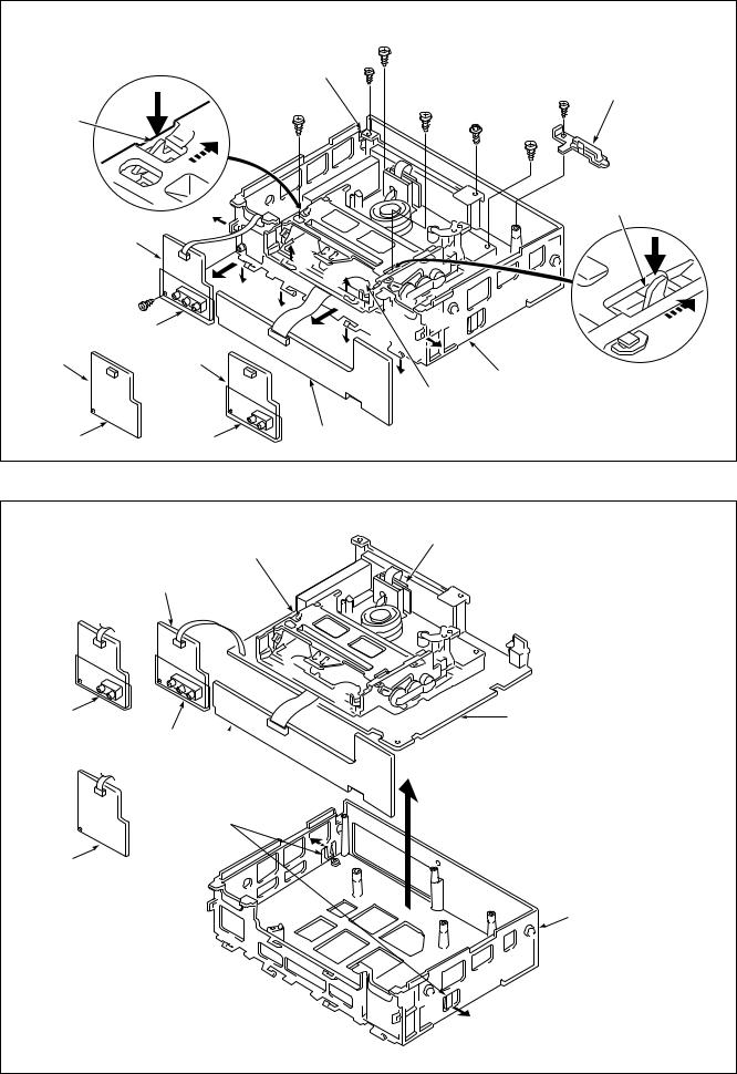
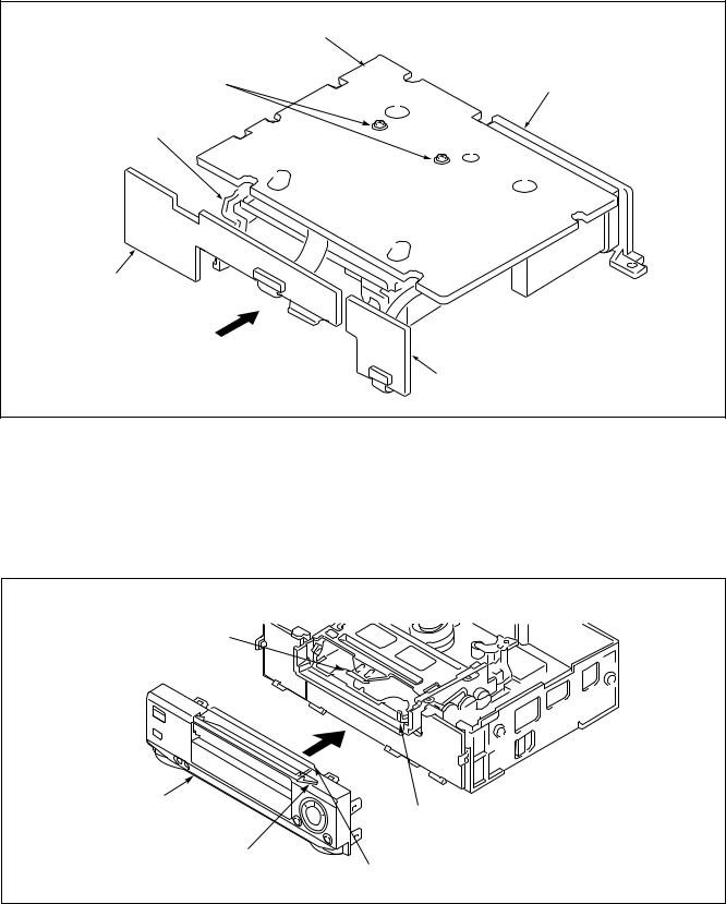
REMOVING THE MECHANISM MAIN UNIT AND THE CP-1 PWB ASSEMBLY (Fig.1-1-2 and 1-1-3)
After removing the cabinet parts, remove the mechanism unit and the CP-1 PWB assembly connected as follows.
1.Spread out the lock clamps (C) in the arrow direction slightly and remove the TM-1 PWB as shown in Fig. 1-1-2.
2.Remove the screw 4 at the chassis.
3.Remove the red screw 5 in the chassis, the red screw 6, and remove the holder in this order. (SLV-L45AR) Remove the screw 5 in the chassis, the screw 6, and the holder in this order. (SLV-L65HFAR/L75HFAR)
4.Remove the two screws 7 and two screws 8 of the mechanism unit. The two screws 8 of the cassette tray can be removed easily by pushing the tray lock lever in the arrow direction to remove the lock as shown in the enlarge view A and by pushing the lid opener lever in the arrow direction to remove the lock as shown in the enlarge view B.
5.Lift up the whole mechanism unit and main board (CP-1 PWB assembly), and as shown in Fig. 1-1-3, push the two lock clamps (D) of the chassis in the arrow direction so that they can be removed from the chassis.
1
Cabinet
1
1
1
Clamps(A)
Main Unit
Front Panel
Bottom Cover
2
2 |
2 |
|
|
2 |
Fig. 1-1-1 |
2-1
|
A |
|
7 |
|
|
Terminal Board |
|
||
|
|
|
5 |
Holder |
|
|
|
|
|
Tray Lock Lever |
|
|
|
6 |
|
|
|
|
|
|
|
8 |
8 |
7 |
|
|
4 |
||
|
|
|
|
|
|
|
|
|
Lid Opener Lever |
TM-2 PWB |
(B) |
|
|
|
|
|
|
|
|
|
|
|
(C) |
|
|
|
(B) |
(C) |
B |
3 |
|
(C) |
|
|
|
|
|
(C) |
|
SLV-L75HFAR |
|
(C) |
|
|
|
|
|
(C) |
|
TM-2 PWB |
TM-2 PWB |
|
|
|
|
|
|
|
Chassis |
|
|
|
Cassette Tray |
|
SLV-L65HFAR |
SLV-L45AR |
TM-1 PWB |
Fig. 1-1-2 |
|
|
||||
VP-1 PWB Assembly
Mechanism Main Unit
TM-2 PWB
SLV-L45AR |
CP-1 PWB Assembly |
SLV-L75HFAR
TM-1 PWB
Clamps(D)
SLV-L65HFAR
Chassis
Fig. 1-1-3
2-2
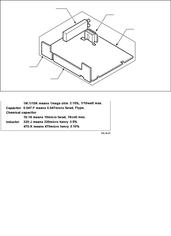
1-2. TEMPORARILY SETTING UP AND CONNECTING CP-1 PWB ASSEMBLY
The following is an example of how to place and connect the main board without a jig, when repairing the CP-1 PWB assembly.
1.Place the mechanism unit and main board up side down as a whole on a flat surface with foil side of the main board facing up.
2.Operate the unit using the buttons on TM-1 PWB or the remote control.
CP-1 PWB Assembly (Foil side)
Screws 9 |
Terminal Boord |
Mechanism Main Unit
TM-1 PWB
Cassette Compartment
TM-2 PWB
Fig. 1-1-4
1-3. INSTALLATION OF THE FRONT PANEL
When installing the front panel to the chassis after repaires and adjustments.
1.Pressing down the door opener lever of the mechanism main unit.
2.Set the cassette door to half-opened state as shown in Fig. 1-1-5, and install the front panel to the chassis.
Note: Opened cassette door position does not install the front panel to the chassis.
Jutted part of
Cassette Holder
Front Panel
Door Opener Lever
Cassette Door
(Position A) Cassette Door
(Position B)
Fig. 1-1-5
2-3 E
SLV-L45AR/L65HFAR/L75HFAR
SECTION 3
DIAGRAMS
CIRCUIT BOARDS LOCATION
3 in 1 Tuner
(Tuner/IF/RF Conv.)
VP-1 PWB Assembly
CP-1 PWB Assembly
TM-2 PWB
TM-1 PWB
3-1
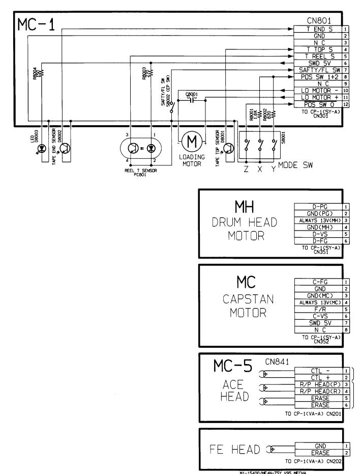
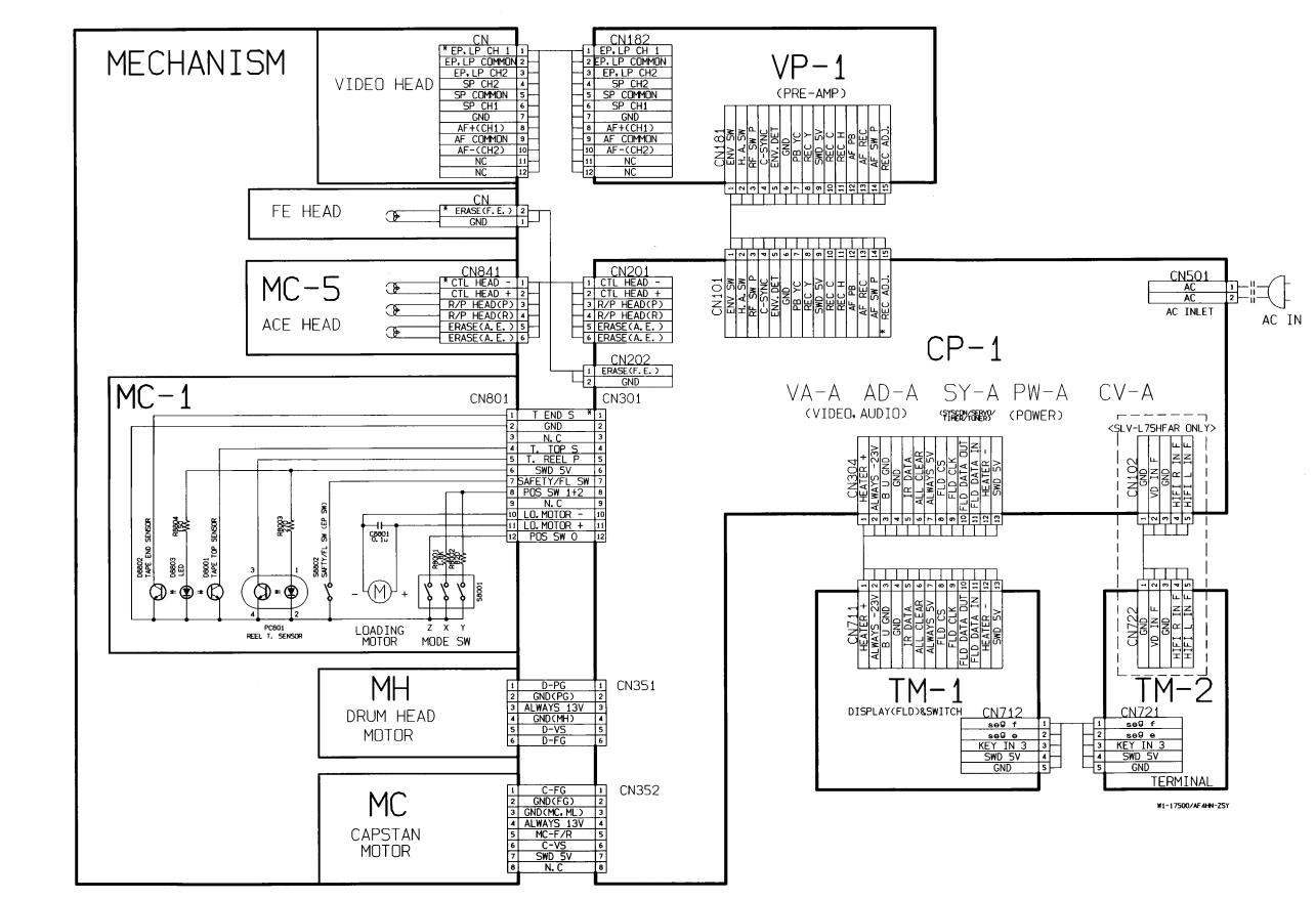
MECHANISM CONNECTION DIAGRAM
3-2
SLV-L45AR/L65HFAR/L75HFAR
OVERALL WIRING DIAGRAM (SLV-L45AR)
3-3 |
3-4 |
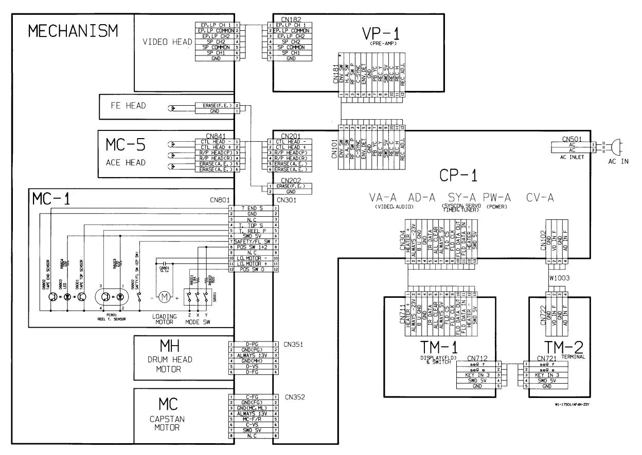
SLV-L45AR/L65HFAR/L75HFAR
OVERALL WIRING DIAGRAM (SLV-L65HFAR/L75HFAR)
3-5 |
3-6 |
SLV-L45AR/L65HFAR/L75HFAR
SYSTEM CONTROL & SERVO CIRCUIT DIAGRAM (SLV-L45AR)
3-7 |
3-8 |
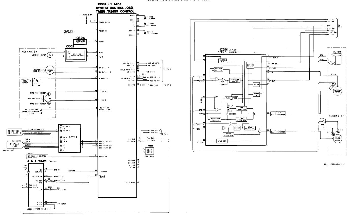
SLV-L45AR/L65HFAR/L75HFAR
SYSTEM CONTROL & SERVO CIRCUIT DIAGRAM (SLV-L65HFAR/L75HFAR)
3-9 |
3-10 |
SLV-L45AR/L65HFAR/L75HFAR
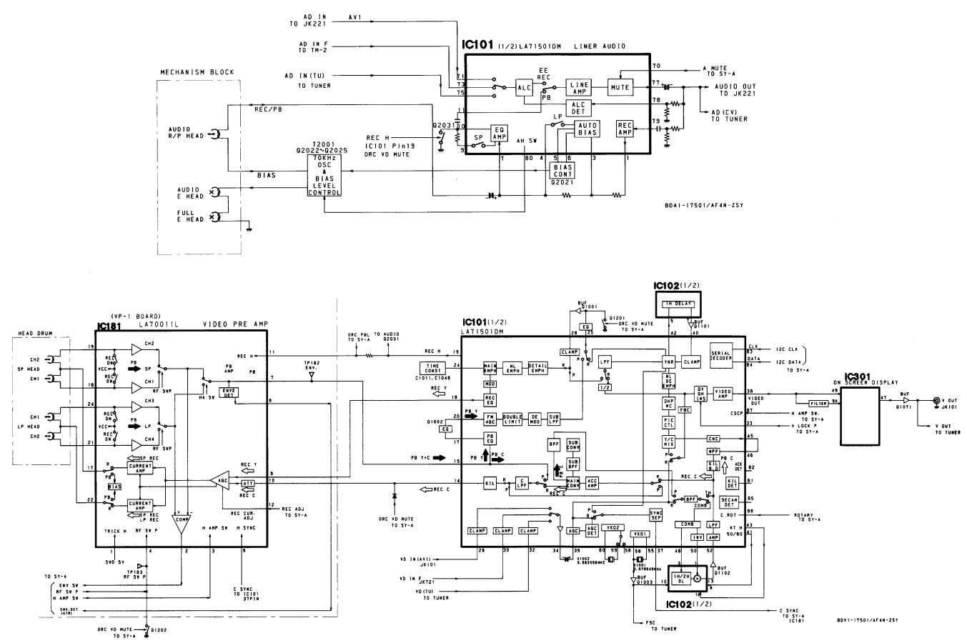
AUDIO CIRCUIT DIAGRAM (SLV-L45AR)
VIDEO CIRCUIT DIAGRAM (SLV-L45AR)
3-11 |
3-12 |
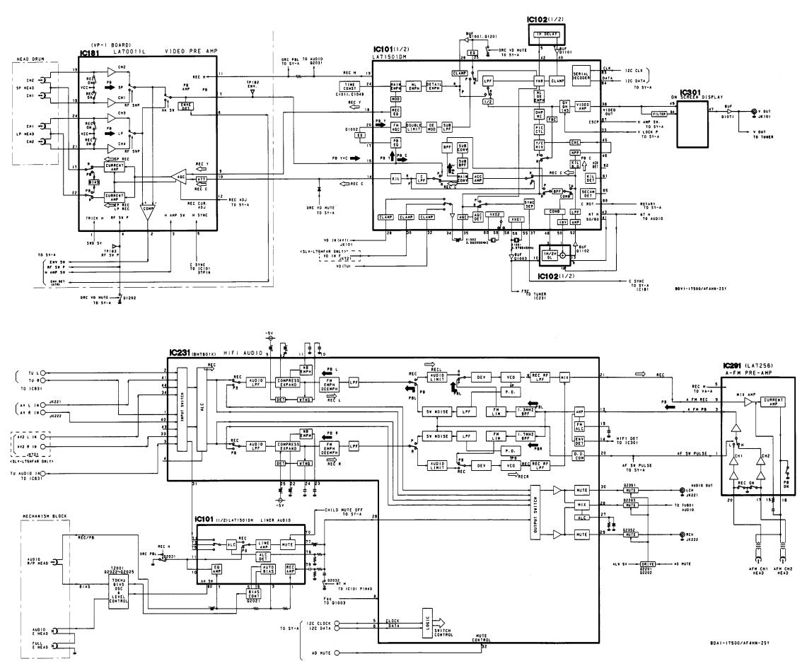
SLV-L45AR/L65HFAR/L75HFAR
VIDEO CIRCUIT DIAGRAM (SLV-L65HFAR/L75HFAR)
AUDIO CIRCUIT DIAGRAM (SLV-L65HFAR/L75HFAR)
3-13 |
3-14E |
SLV-L45AR/L65HFAR/L75HFAR
SECTION 4
SCHEMATIC DIAGRAMS AND PRINTED WIRING BOARDS
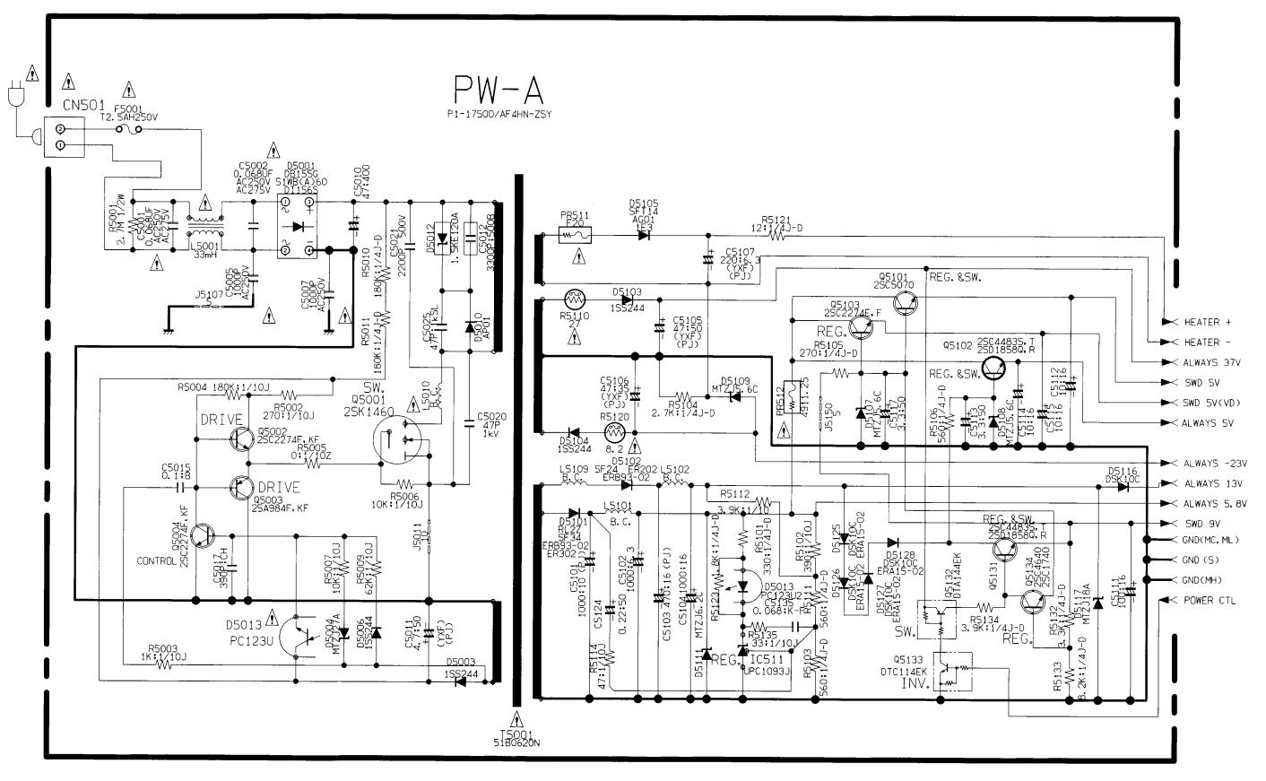
CP-1 BOARD (PW-A) POWER SUPPLY CIRCUIT DIAGRAM
4-1 |
4-2 |
SLV-L45AR/L65HFAR/L75HFAR
CP-1 BOARD (VA-A) VIDEO, AUDIO & TUNER CIRCUIT DIAGRAM (SLV-L45AR)
4-3 |
4-4 |

SLV-L45AR/L65HFAR/L75HFAR
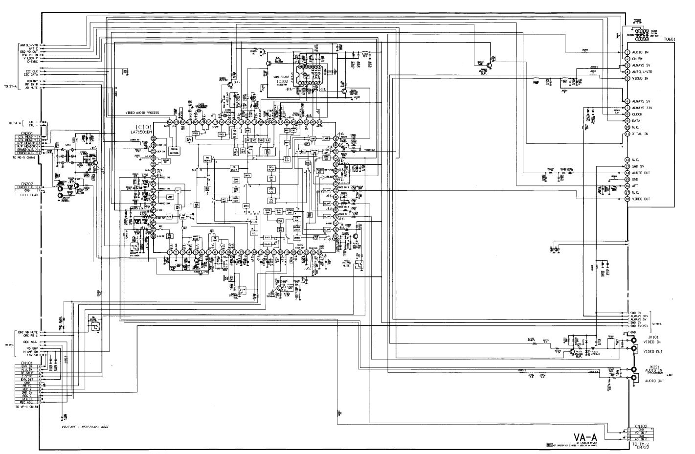
CP-1 BOARD (VA-A) VIDEO, AUDIO & TUNER CIRCUIT DIAGRAM (SLV-L65HFAR/L75HFAR)
4-5 |
4-6 |
SLV-L45AR/L65HFAR/L75HFAR
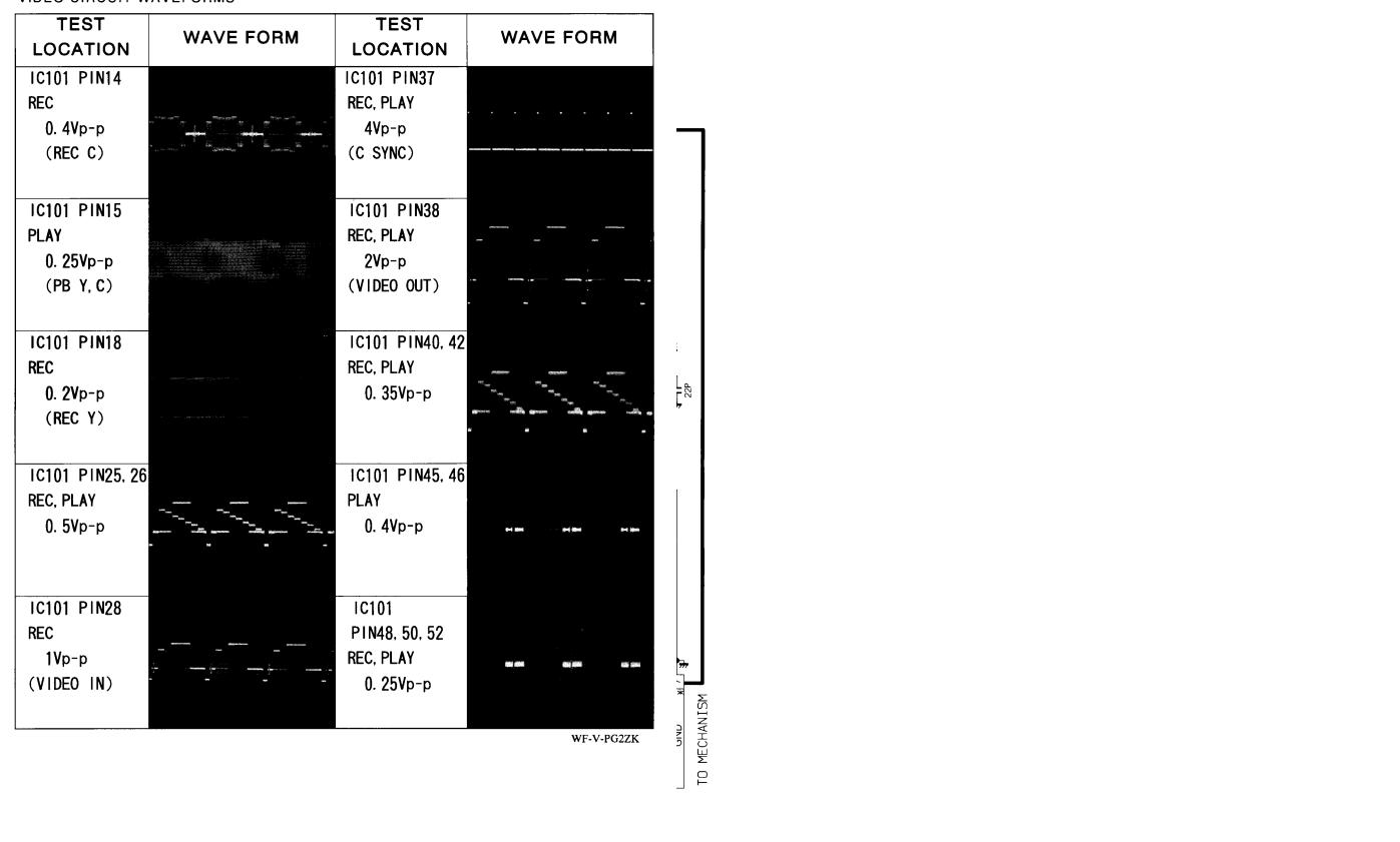
VIDEO CIRCUIT WAVEFORMS
VP-1 BOARD VIDEO PRE-AMP CIRCUIT DIAGRAM (SLV-L45AR)
4-7 |
4-8 |
 Loading...