


3-867-232-12 (1)
Trinitronâ Color
Computer Display
Operating Instructions |
|
|
US |
||
|
|
|
|
||
Mode d’emploi |
|
|
|
FR |
|
|
|
|
|||
Manual de instrucciones |
|
ES |
|||
|
|
|
|
|
|
|
|
|
|
|
CS |
CPD-G500
© 1999 by Sony Corporation
Owner’s Record
The model and serial numbers are located at the rear of the unit. Record these numbers in the spaces provided below. Refer to them whenever you call upon your dealer regarding this product. Model No. Serial No.
WARNING
To prevent fire or shock hazard, do not expose the unit to rain or moisture.
Dangerously high voltages are present inside the unit. Do not open the cabinet. Refer servicing to qualified personnel only.
FCC Notice
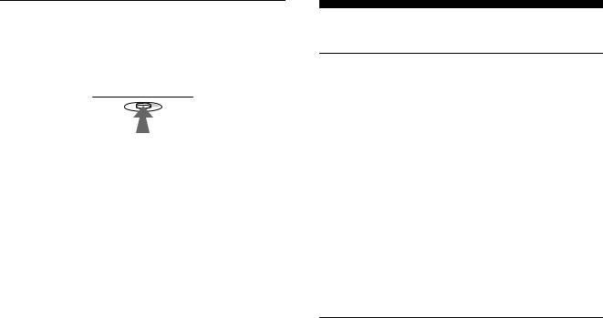
This equipment has been tested and found to comply with the limits for a Class B digital device, pursuant to Part 15 of the FCC Rules. These limits are designed to provide reasonable protection against harmful interference in a residential installation. This equipment generates, uses, and can radiate radio frequency energy and, if not installed and used in accordance with the instructions, may cause harmful interference to radio communications. However, there is no guarantee that interference will not occur in a particular installation. If this equipment does cause harmful interference to radio or television reception, which can be determined by turning the equipment off and on, the user is encouraged to try to correct the interference by one or more of the following measures:
–Reorient or relocate the receiving antenna.
–Increase the separation between the equipment and receiver.
–Connect the equipment into an outlet on a circuit different from that to which the receiver is connected.
–Consult the dealer or an experienced radio/TV technician for
help.
You are cautioned that any changes or modifications not expressly approved in this manual could void your authority to operate this equipment.
IMPORTADOR (Para Mexico unicamente/For Mexico only)
Sony Electronicos de Mexico, S.A. de C.V. Henry Ford No.29
Fraccionamiento San Nicolas, Tlalnepantla Estado de Mexico, CP54030
Tel.: 321-1000
R.F.C. SEM-941001-BJA
IMPORTANTE
Para prevenir cualquier mal funcionamiento y evitar daños, por favor, lea detalladamente este manual de instrucciones antes de conectar y operar este equipo.
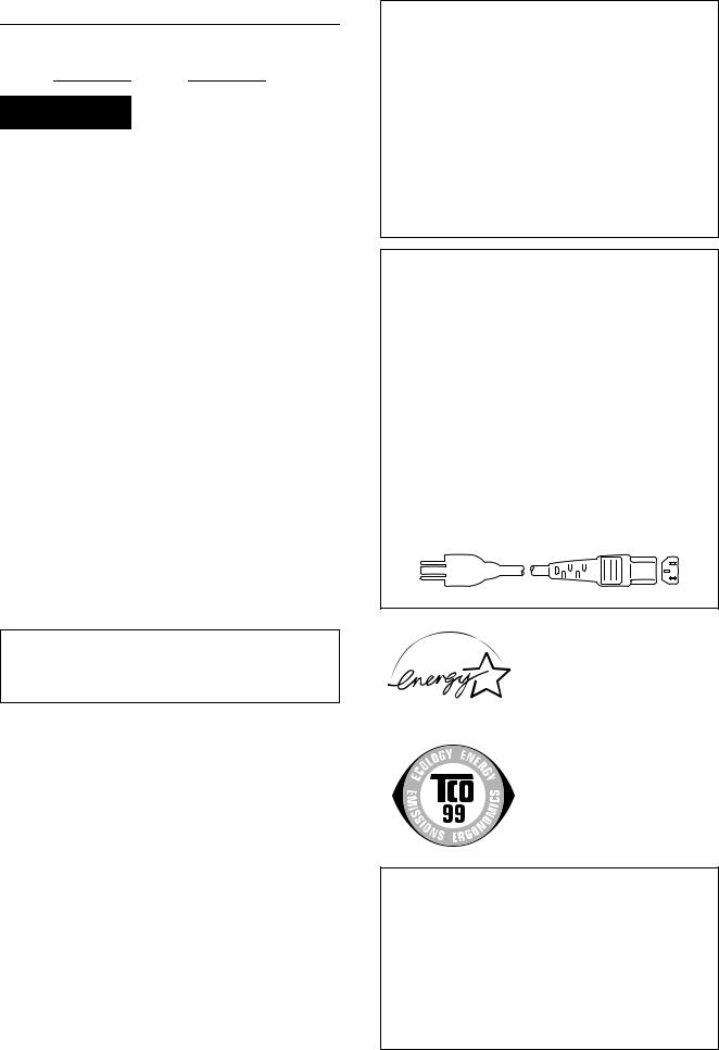
INFORMATION
This product complies with Swedish National Council for Metrology (MPR) standards issued in December 1990 (MPR II) for very low frequency (VLF) and extremely low frequency (ELF).
INFORMATION
Ce produit est conforme aux normes du Swedish National Council for Metrology de décembre 1990 (MPR II) en ce qui concerne les fréquences très basses (VLF) et extrêmement basses (ELF).
Hinweis
Dieses Gerät erfüllt bezüglich tieffrequenter (very low frequency) und tiefstfrequenter (extremely low frequency) Strahlung die Vorschriften des „Swedish National Council for Metrology (MPR)“ vom Dezember 1990 (MPR II).
INFORMACIÓN
Este producto cumple las normas del Consejo Nacional Sueco para Metrología (MPR) emitidas en diciembre de 1990 (MPR II) para frecuencias muy bajas (VLF) y frecuencias extremadamente bajas (ELF).
Dieses Garät entspricht den folgenden europäischen EMVVorschriften für Betrieb in Wohngebieten, gewerblicher Gebleten und Leichtindustriegebieten.
EN55022/1994 Klasse B
EN50082-1/1997
EN61000-3-2/1995
Hinweise
•Aus ergonomischen Gründen wird empfohlen, die Grundfarbe Blau nicht auf dunklem Untergrund zu verwenden (schlechte Erkennbarkeit, Augenbelastung bei zu geringem Zeichenkontrast).
•Aus ergonomischen Gründen (flimmern) sollten nur Darstellungen bei Vertikalfrequenzen ab 70 Hz (ohne Zeilensprung) verwendet werden.
•Die Konvergenz des Bildes kann sich auf Grund des Magnetfeldes am Ort der Aufstellung aus der korrekten Grundeinstellung verändern. Zur Korrektur empfiehlt es sich deshalb, die Regler an der Frontseite für Konvergenz so einzustellen, daß die getrennt sichtbaren Farblinien für Rot, Grün und Blau bei z.B. der Darstellung eines Buchstabens zur Deckung (Konvergenz) gelangen.
Siehe hierzu auch die Erklärungen zu Konvergenz.
NOTICE
This notice is applicable for USA/Canada only.
If shipped to USA/Canada, install only a UL LISTED/CSA LABELLED power supply cord meeting the following
specifications: |
|
|
|
|||||
SPECIFICATIONS |
|
|
|
|||||
Plug Type |
Nema-Plug 5-15p |
|||||||
Cord |
Type SVT or SJT, minimum 3 × 18 AWG |
|||||||
Length |
Maximum 15 feet |
|||||||
Rating |
Minimum 7 A, 125 V |
|||||||
|
|
|
|
|
|
|
|
|
|
|
|
|
|
|
|
|
|
|
|
|
|
|
|
|
|
|
|
|
|
|
|
|
|
|
|
|
|
|
|
|
|
|
|
|
|
|
|
|
|
|
|
|
|
|
|
|
|
|
|
|
|
|
|
|
|
|
|
|
|
|
|
|
|
|
|
|
|
|
|
|
Sony CPD-G500
Sony Electronics Inc.
1 Sony Drive, Park Ridge, NJ. 07656 USA
201-930-6970
This device complies with Part 15 of the FCC Rules. Operation is subject to the following two conditions: (1) This device may not cause harmful interference, and (2) this device must accept any interference received, including interference that may cause undesired operation.
2
Table of Contents
Precautions. . . . . . . . . . . . . . . . . . . . . . . . . . . . . . . . . . . . . . . . . . . . 4
Identifying parts and controls . . . . . . . . . . . . . . . . . . . . . . . . . . . . . . 5
Setup . . . . . . . . . . . . . . . . . . . . . . . . . . . . . . . . . . . . . . . . . .6
Step 1: Connect your monitor to your computer . . . . . . . . . . . . . . . 6
Step 2: Connect the power cord. . . . . . . . . . . . . . . . . . . . . . . . . . . . 7
Step 3: Turn on the monitor and computer . . . . . . . . . . . . . . . . . . . 7
Selecting the on-screen menu language (LANG) . . . . . . . . . . . . . . . 8
Selecting the input signal . . . . . . . . . . . . . . . . . . . . . . . . . . . . . . . . . 8
Customizing Your Monitor . . . . . . . . . . . . . . . . . . . . . . . .9
Navigating the menu. . . . . . . . . . . . . . . . . . . . . . . . . . . . . . . . . . . . . 9
Adjusting the brightness and contrast. . . . . . . . . . . . . . . . . . . . . . . 10
Automatically sizing and centering the picture (AUTO) . . . . . . . . . 11
Adjusting the size of the picture (SIZE) . . . . . . . . . . . . . . . . . . . . . 11
Adjusting the centering of the picture (CENTER) . . . . . . . . . . . . . . 11
Enlarging or reducing the picture (ZOOM) . . . . . . . . . . . . . . . . . . . 11 US
Adjusting the shape of the picture (GEOM) . . . . . . . . . . . . . . . . . . 12
Adjusting the convergence (CONV) . . . . . . . . . . . . . . . . . . . . . . . . 12
Adjusting the quality of the picture (SCREEN) . . . . . . . . . . . . . . . . 13
Adjusting the color of the picture (COLOR) . . . . . . . . . . . . . . . . . . 13
Additional settings (OPTION) . . . . . . . . . . . . . . . . . . . . . . . . . . . . . 15
Resetting the adjustments . . . . . . . . . . . . . . . . . . . . . . . . . . . . . . . 16
•Trinitron â is a registered trademark of Sony Corporation.
•Macintosh is a trademark licensed to Apple Computer, Inc., registered in the U.S.A. and other countries.
•Windows â and MS-DOS are registered trademarks of Microsoft Corporation in the United States and other countries.
•IBM PC/AT and VGA are registered trademarks of IBM Corporation of the U.S.A.
•VESA and DDC ä are trademarks of the Video Electronics Standard Association.
•ENERGY STAR is a U.S. registered mark.
•All other product names mentioned herein may be the trademarks or registered trademarks of their respective companies.
•Furthermore, “ ä” and “ â” are not mentioned in each case in this manual.
Technical Features . . . . . . . . . . . . . . . . . . . . . . . . . . . . .16
Preset and user modes. . . . . . . . . . . . . . . . . . . . . . . . . . . . . . . . . . 16 Power saving function. . . . . . . . . . . . . . . . . . . . . . . . . . . . . . . . . . . 16
Troubleshooting. . . . . . . . . . . . . . . . . . . . . . . . . . . . . . . .17
If thin lines appear on your screen (damper wires). . . . . . . . . . . . . 17 On-screen messages . . . . . . . . . . . . . . . . . . . . . . . . . . . . . . . . . . . 17 Trouble symptoms and remedies . . . . . . . . . . . . . . . . . . . . . . . . . . 18 Self-diagnosis function . . . . . . . . . . . . . . . . . . . . . . . . . . . . . . . . . . 20
Specifications. . . . . . . . . . . . . . . . . . . . . . . . . . . . . . . . . .20
Appendix. . . . . . . . . . . . . . . . . . . . . . . . . . . . . . . . . . . . . . . i
Preset mode timing table . . . . . . . . . . . . . . . . . . . . . . . . . . . . . . . . . .i TCO’99 Eco-document . . . . . . . . . . . . . . . . . . . . . . . . . . . . . . . . . . . .i
3
Precautions
Warning on power connections
•Use the supplied power cord. If you use a different power cord, be sure that it is compatible with your local power supply.
For the customers in the U.S.A.
If you do not use the appropriate cord, this monitor will not conform to mandatory FCC standards.
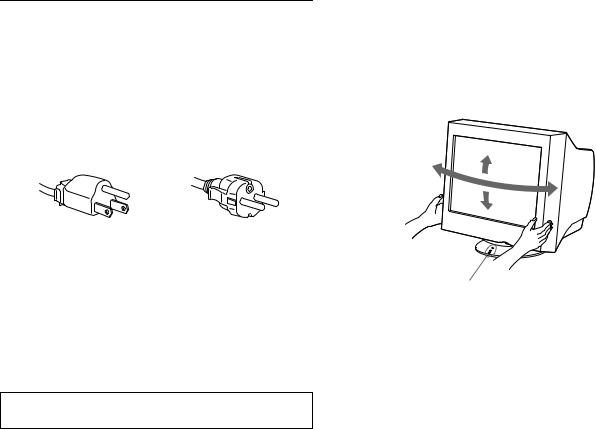
Example of plug types
for 100 to 120 V AC |
for 200 to 240 V AC |
•Before disconnecting the power cord, wait at least 30 seconds after turning off the power to allow the static electricity on the screen’s surface to discharge.
•After the power is turned on, the screen is demagnetized (degaussed) for about 2 seconds. This generates a strong magnetic field around the screen which may affect data stored on magnetic tapes and disks placed near the monitor. Be sure to keep magnetic recording equipment, tapes, and disks away from the monitor.
The equipment should be installed near an easily accessible outlet.
Installation
Do not install the monitor in the following places:
•on surfaces (rugs, blankets, etc.) or near materials (curtains, draperies, etc.) that may block the ventilation holes
•near heat sources such as radiators or air ducts, or in a place subject to direct sunlight
•in a place subject to severe temperature changes
•in a place subject to mechanical vibration or shock
•on an unstable surface
•near equipment which generates magnetism, such as a transformer or high voltage power lines
•near or on an electrically charged metal surface
Maintenance
•Clean the screen with a soft cloth. If you use a glass cleaning liquid, do not use any type of cleaner containing an anti-static solution or similar additive as this may scratch the screen’s coating.
•Do not rub, touch, or tap the surface of the screen with sharp or abrasive items such as a ballpoint pen or screwdriver. This type of contact may result in a scratched picture tube.
•Clean the cabinet, panel and controls with a soft cloth lightly moistened with a mild detergent solution. Do not use any type of abrasive pad, scouring powder or solvent, such as alcohol or benzene.
Transportation
When you transport this monitor for repair or shipment, use the original carton and packing materials.
Use of the tilt-swivel
This monitor can be adjusted within the angles shown below. To find the center of the monitor’s turning radius, align the center of the monitor’s screen with the centering dots on the stand.
Hold the monitor at the bottom with both hands when you turn it horizontally or vertically. Be careful not to pinch your fingers at the back of the monitor when you tilt the monitor up vertically.
90°
15°
90°
5°
Centering dots
4
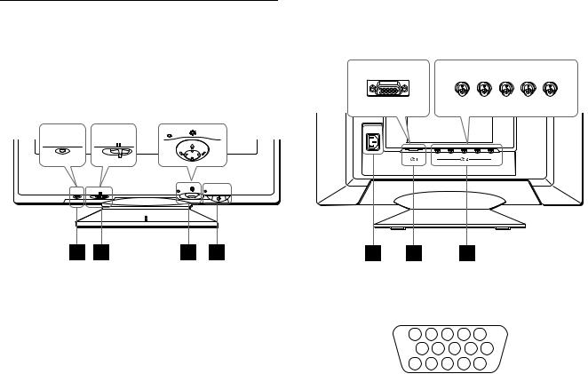
Identifying parts and controls
See the pages in parentheses for further details.
Front |
Rear |
forward side |
|
forward side |
|
|
rear side |
rear side |
|
MENU |
|
|
AC IN |
|
RESET |
INPUT HD15 BNC |
|
|
R |
G B HD VD |
|
(HD15) |
(BNC) |
|
MENU |
|
RESET |
INPUT HD15 BNC |
|
1RESET (reset) button (page 16)
This button resets the adjustments to the factory settings.
2 INPUT (input) switch (page 8)
6Video input 1 connector (HD15) (y1) (page 6)
This connector inputs RGB video signals (0.700 Vp-p, positive) and sync signals.
This switch selects the HD15 or BNC video input signal.
3Control button (page 10)
The control button is used to display the menu and make adjustments to the monitor, including brightness and contrast adjustments.
41 (power) switch and indicator (pages 7, 16, 20)
This button turns the monitor on and off. The power indicator lights up in green when the monitor is turned on, and either flashes in green and orange, or lights up in orange when the monitor is in power saving mode.
5AC IN connector (page 7)
This connector provides AC power to the monitor.
|
5 |
|
4 |
3 |
2 |
1 |
|
|
|
10 |
9 |
8 |
7 |
6 |
|
|
|
|
US |
|||||||
|
15 |
14 |
13 12 |
11 |
|
|||
|
|
|
||||||
|
|
|
|
|
|
|
|
|
Pin No. |
Signal |
|
|
|
|
|
|
|
|
|
|
|
|
|
|
|
|
1 |
Red |
|
|
|
|
|
|
|
|
|
|
|
|
|
|
|
|
2 |
Green |
|
|
|
|
|
|
|
|
(Sync on Green) |
|
|
|
|
|||
|
|
|
|
|
|
|
|
|
3 |
Blue |
|
|
|
|
|
|
|
|
|
|
|
|
|
|
||
4 |
ID (Ground) |
|
|
|
|
|
||
|
|
|
|
|
|
|
||
5 |
DDC Ground* |
|
|
|
|
|
||
|
|
|
|
|
|
|
||
6 |
Red Ground |
|
|
|
|
|
||
|
|
|
|
|
|
|
||
7 |
Green Ground |
|
|
|
|
|
||
|
|
|
|
|
|
|
||
8 |
Blue Ground |
|
|
|
|
|
||
|
|
|
|
|
|
|
|
|
9 |
DDC + 5V* |
|
|
|
|
|
|
|
|
|
|
|
|
|
|
|
|
10 |
Ground |
|
|
|
|
|
|
|
|
|
|
|
|
|
|
||
11 |
ID (Ground) |
|
|
|
|
|
||
|
|
|
|
|||||
12 |
Bi-Directional Data (SDA)* |
|
||||||
|
|
|
|
|
|
|
|
|
13 |
H. Sync |
|
|
|
|
|
|
|
|
|
|
|
|
|
|
|
|
14 |
V. Sync |
|
|
|
|
|
|
|
|
|
|
|
|
|
|||
15 |
Data Clock (SCL)* |
|
|
|
|
|||
|
|
|
|
|
|
|
|
|
* DDC (Display Data Channel) is a standard of VESA.
7Video input 2 connector (BNC) (y2) (page 6)
This connector inputs RGB video signals (0.700 Vp-p, positive) and sync signals.
5

Setup
Before using your monitor, check that the following accessories are included in your carton:
•Power cord (1)
•HD15 video signal cable (1)
•Current G3 adapter (for beige system) (1)
•Windows Monitor Information Disk (1)
•Warranty card (1)
•Notes on cleaning the screen’s surface (1)
•This instruction manual (1)
Step 1: Connect your monitor to your computer
Turn off the monitor and computer before connecting.
Notes
•Do not touch the pins of the video signal cable connector as this might bend the pins.
•When connecting the video signal cable, check the alignment of the HD15 connector. Do not force the connector in the wrong way or the pins might bend.
xConnecting to an IBM PC/AT or compatible computer
AC IN
R |
G |
B |
HD |
VD |
(HD15) |
|
(BNC) |
|
|
xConnecting to a Macintosh or compatible computer
AC IN
R |
G |
B |
HD VD |
(HD15)
to HD15
Current G3 adapter (for beige system) (supplied)*
Macintosh or |
to video |
HD15 video signal |
|
cable (supplied) |
|||
compatible computer |
output |
||
|
*Connect the supplied Macintosh adapter to the computer before connecting the cable.
This adapter is compatible with Macintosh LC, Performa, Quadra, Power Macintosh, and Power Macintosh G3 series computers that have two rows of pins. If you are connecting to the other version of Power Macintosh G3 series with three rows of pins or models other than those stated above, you will need a different adapter (not supplied).
x Connecting to the five BNC connectors
AC IN
R |
G |
B |
HD |
VD |
(HD15) |
|
(BNC) |
|
|
to HD15
to video output
to VIDEO IN R/G/B


 HD15 video signal IBM PC/AT or compatible cable (supplied) computer
Refer to the preceding examples to connect to your computer.
to SYNC IN HD/VD
video signal cable (SMF-400, not supplied)*
*Connect the cables from left to right in the following order: Red-Green- Blue-HD-VD.
Note
Plug & Play (DDC) does not apply to the five BNC connectors. If you want to use Plug & Play, connect your computer to the HD15 connector using the supplied video signal cable.
6
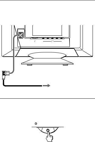
Step 2: Connect the power cord
With the monitor and computer switched off, first connect the power cord to the monitor, then connect it to a power outlet.
AC IN
R |
G |
B |
HD |
VD |
(HD15) |
|
(BNC) |
|
|
to AC IN
to a power outlet
power cord (supplied)
Step 3: Turn on the monitor and computer
First turn on the monitor, then turn on the computer.
The installation of your monitor is complete.
If necessary, use the monitor’s controls to adjust the picture.
If no picture appears on your screen
•Check that the monitor is correctly connected to the computer.
•If NO INPUT SIGNAL appears on the screen, try changing the input signal (page 8), and confirm that your computer’s graphic board is completely seated in the correct bus slot.
•If you are replacing an old monitor with this model and OUT OF SCAN RANGE appears on the screen, reconnect the old monitor. Then adjust the computer’s graphic board so that the horizontal frequency is between 30 – 121 kHz, and the vertical frequency is between 48 – 160 Hz.
For more information about the on-screen messages, see “Trouble symptoms and remedies” on page 18.
For customers using Windows 95/98
To maximize the potential of your monitor, install the new model information file from the supplied Windows Monitor Information Disk onto your PC.
This monitor complies with the “VESA DDC” Plug & Play standard. If your PC/graphics board complies with DDC, select “Plug & Play Monitor (VESA DDC)” or this monitor’s model name as the monitor type in the “Control Panel” of Windows 95/98. If your PC/graphics board has difficulty communicating with this monitor, load the Windows Monitor Information Disk and select this monitor’s model name as the monitor type.
For customers using Windows NT4.0 |
US |
Monitor setup in Windows NT4.0 is different from Windows 95/98 and does not involve the selection of monitor type. Refer to the Windows NT4.0 instruction manual for further details on adjusting the resolution, refresh rate, and number of colors.
Adjusting the monitor’s resolution and color number
Adjust the monitor’s resolution and color number by referring to your computer’s instruction manual. The color number may vary according to your computer or video board. The color palette setting and the actual number of colors are as follows:
•High Color (16 bit) t 65,536 colors
•True Color (24 bit) t about 16.77 million colors In true color mode (24 bit), speed may be slower.
7
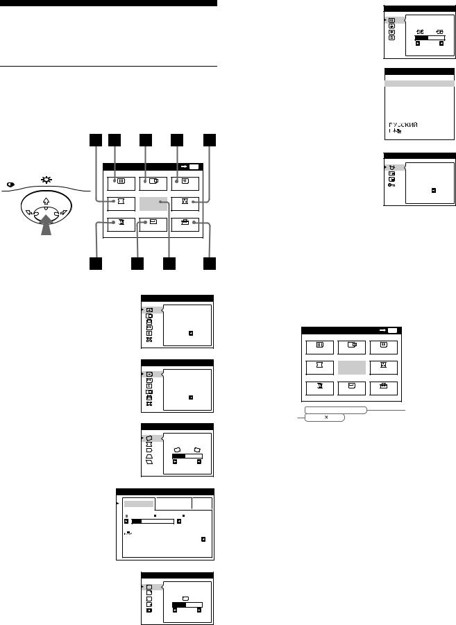
Selecting the on-screen menu language (LANG)
English, French, German, Spanish, Italian, Dutch, Swedish, Russian and Japanese versions of the on-screen menus are available. The default setting is English.
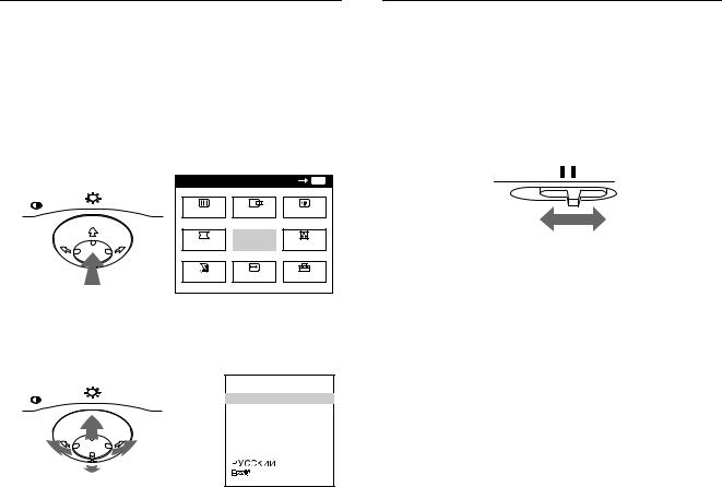
1Press the center of the control button.
See page 10 for more information on using the control button.
MENU |
MENU |
|
OK |
MENU |
|
SCREEN |
CENTER |
CONV |
|
|
GEOM |
EXIT |
COLOR |
|
|
LANG |
SIZE |
OPTION |
|
2Move the control button to highlight 
 LANG and press the center of the control button again.
MENU |
L ANGUAGE |
|
|
 ENGL I SH
FRANÇA I S
DEUT SCH
ESPAÑOL
I T A L I ANO
NEDER L ANDS
SVENSKA
3Move the control button m/M to select a language.
•ENGLISH
•FRANÇAIS: French
•DEUTSCH: German
•ESPAÑOL: Spanish
•ITALIANO: Italian
•NEDERLANDS: Dutch
•SVENSKA: Swedish
•


 : Russian
•
 : Japanese
To close the menu
Press the center of the control button once to return to the main MENU, and twice to return to normal viewing. If no buttons are pressed, the menu closes automatically after about 30 seconds.
To reset to English
Press the RESET button while the LANGUAGE menu is displayed on the screen.
Selecting the input signal
You can connect two computers to this monitor using the HD15 and BNC connectors. To select one of the two computers, use the INPUT switch.
Move the INPUT switch.
The selected connector appears on the screen for 3 seconds.
INPUT HD15 BNC
“HD15” or “BNC” appears on the screen.
Note
If no signal is input to the selected connector, NO INPUT SIGNAL appears on the screen. After a few seconds, the monitor enters the power saving mode. If this happens, switch to the other connector.
8
Customizing Your Monitor
You can make numerous adjustments to your monitor using the on-screen menu.
Navigating the menu
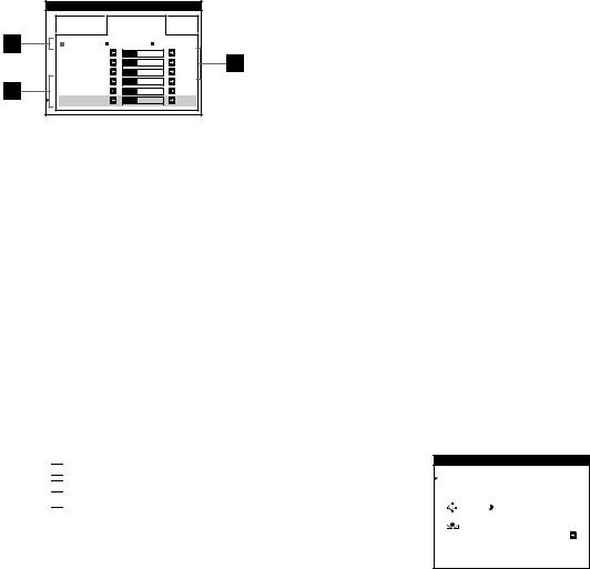
Press the center of the control button to display the main MENU on your screen. See page 10 for more information on using the control button.
6CONV (page 12)
Select the CONV menu to adjust the picture’s horizontal and vertical convergence.
7LANG (page 8)
Select LANG to choose the onscreen menu’s language.
CONVERGENCE |
TOP |
BOT |
2 6 |
L ANGUAGE
 ENGL I SH
FRANÇA I S
DEUT SCH
ESPAÑOL
I T A L I ANO
NEDER L ANDS
SVENSKA
MENU |
|
OK |
MENU |
MENU |
|
|
|
SCREEN |
CENTER |
CONV |
|
GEOM |
EXIT |
COLOR |
|
LANG |
SIZE |
OPTION |
|
Use the control button to select one of the following menus.
1CENTER (page 11)
Selects the CENTER menu to adjust the picture’s centering, size or zoom.
2SIZE (page 11)
Selects the SIZE menu to adjust the picture’s size, centering or zoom.
S I ZE / CENTER |
AUTO |
ON |
S I ZE / CENTER |
AUTO
ON
3 GEOM (page 12) |
|
GEOMETRY |
|
|
Select the GEOM menu to adjust the |
|
|
||
picture’s rotation and shape. |
|
|
|
|
|
|
|
2 6 |
|
4 COLOR (page 13) |
COLOR |
|
|
|
Select the COLOR menu to |
EASY |
EXPERT |
s RGB |
|
adjust the picture’s color |
||||
5 0 0 0 K 6 5 0 0 K 9 3 0 0 K |
||||
temperature. You can use |
||||
|
|
5 0 0 0 K |
||
this to match the monitor’s |
I MAGE |
|
||
colors to a printed picture’s |
RES TORA T I ON |
ON |
||
colors. |
|
|
|
|
5 SCREEN (page 13) |
|
SCREEN |
|
|
Select the SCREEN menu to adjust |
L AND I NG |
|
the picture’s quality. You can adjust |
||
|
||
the landing and moire cancellation |
2 6 |
|
effect. |
||
|
8 OPTION (page 15) |
OPT I ON |
||
Select OPTION to adjust the |
DEGAUSS |
||
monitor’s options. The options |
|||
|
|||
include: |
ON |
||
• |
degaussing the screen |
||
|
|||
• |
changing the on-screen menu |
|
|
|
position |
|
|
• |
locking the controls |
|
|
9EXIT
Select EXIT to close the menu.
x Displaying the current input signal |
US |
The horizontal and vertical frequencies of the current input signal are displayed in the main MENU. If the signal matches one of this monitor’s factory preset modes, the resolution is also displayed.
the resolution of the current input signal
MENU |
|
|
|
OK |
MENU |
SCREEN |
CENTER |
CONV |
|||
GEOM |
|
EXIT |
COLOR |
||
LANG |
|
|
SIZE |
OPTION |
|
68 . 7kHz / |
85Hz |
|
|
||
1024 |
768 |
|
|
|
|
the horizontal and vertical frequencies of the current input signal
9
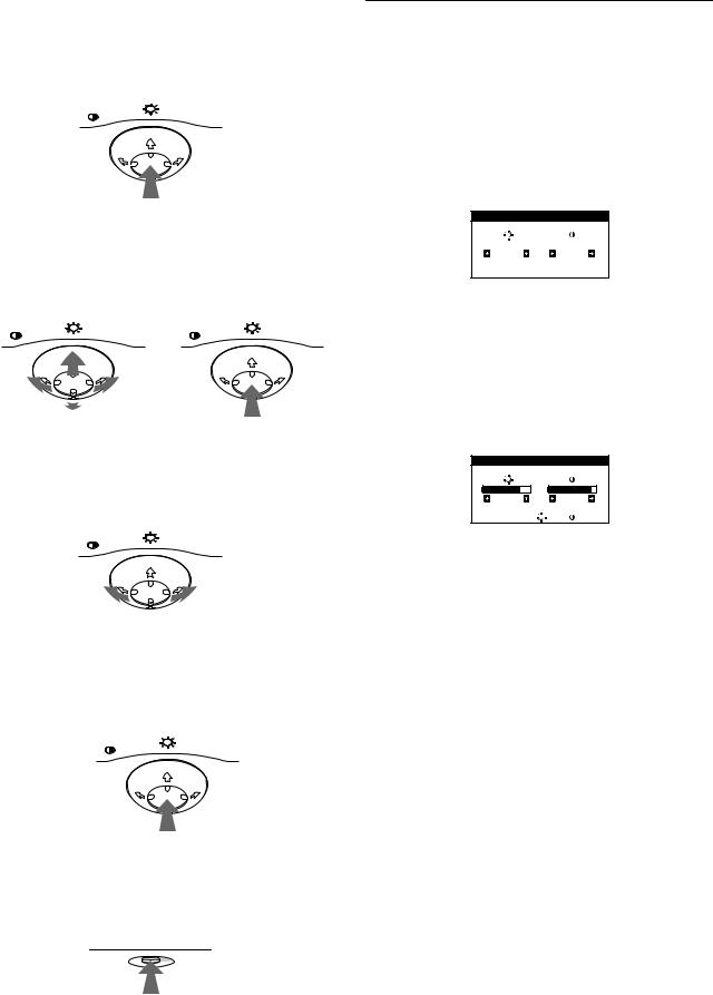
x Using the control button
1Display the main MENU.
Press the center of the control button to display the main MENU on your screen.
MENU
2Select the menu you want to adjust.
Highlight the desired menu by moving the control button towards the rear to go up (M), towards the front to go down (m), and left (<) or right (,) to move sideways.
FRONT
MENU |
MENU |
REAR
3Adjust the menu.
Move the control button left (<) or right (,) to make the adjustment.
MENU
4Close the menu.
Press the center of the control button once to return to the main MENU, and twice to return to normal viewing. If no buttons are pressed, the menu closes automatically after about 30 seconds.
MENU
x Resetting the adjustments
Press the RESET button. See page 16 for more information on resetting the adjustments.
RESET
Adjusting the brightness and contrast
Brightness and contrast adjustments are made using a separate BRIGHTNESS/CONTRAST menu.
These settings are stored in memory for the signals from the currently selected input connector.
1Move the control button in any direction.
The BRIGHTNESS/CONTRAST menu appears on the screen.
BR I GHTNESS / CONTRAS T
|
|
|
|
|
2 6 |
|
2 6 |
||
2Move the control button m/M to adjust the brightness ( ), and </, to adjust the contrast (6).
If you are using the sRGB mode
If you selected the sRGB mode in the COLOR menu, the following BRIGHTNESS/CONTRAST menu appears on the screen.
BR I GHTNESS / CONTRAS T
5 6 |
|
7 6 |
s RGB : |
5 6 |
7 6 |
For more information about using the sRGB mode, see “Adjusting the color of the picture (COLOR)” on page 13.
The menu automatically disappears after about 3 seconds.
10
Automatically sizing and centering the picture (AUTO)
You can easily adjust the picture to fill the screen by using the  (AUTO) item in the SIZE/CENTER menu.
1Press the center of the control button.
The main MENU appears on the screen.
2Move the control button to highlight  SIZE or
 CENTER and press the center of the control button again.
The SIZE/CENTER menu appears on the screen.
3First move the control button m/M to select  (AUTO). Then move the control button ,.
The picture automatically fills the screen.
Notes
•This function is intended for use with a computer running Windows or similar graphic user interface software that provides a full-screen picture. It may not work properly if the background color is dark or if the input picture does not fill the screen to the edges (such as an MSDOS prompt).
•Pictures with an aspect ratio of 5:4 (resolution: 1280 × 1024, 1600 × 1280) are displayed at their actual resolution and do not fill the screen to the edges.
•The displayed image moves for a few seconds while this function is performed. This is not a malfunction.
Adjusting the size of the picture (SIZE)
This setting is stored in memory for the current input signal.
1Press the center of the control button.
The main MENU appears on the screen.
2Move the control button to highlight  SIZE and press the center of the control button again.
The SIZE/CENTER menu appears on the screen.
3First move the control button m/M to select  for horizontal adjustment, or
  for vertical adjustment. Then move the control button </, to adjust the size.
Adjusting the centering of the picture (CENTER)
This setting is stored in memory for the current input signal.
1Press the center of the control button.
The main MENU appears on the screen.
2Move the control button to highlight 
 CENTER and press the center of the control button again.
The SIZE/CENTER menu appears on the screen.
3First move the control button m/M to select 
 for horizontal adjustment, or
  for vertical adjustment. Then move the control button </, to adjust the centering.
Enlarging or reducing the picture (ZOOM)
This setting is stored in memory for the current input signal.
1Press the center of the control button.
The main MENU appears on the screen.
2 |
Move the control button to highlight |
SIZE or |
US |
|
|
||||
|
CENTER and press the center of the control |
|
||
|
button again. |
|
|
|
|
The SIZE/CENTER menu appears on the screen. |
|
||
3 |
Move the control button m/M to select |
|
(zoom), |
|
|
|
|||
|
|
|||
and move </, to enlarge or reduce the picture.
Note
Adjustment stops when either the horizontal or vertical size reaches its maximum or minimum value.
11
Adjusting the shape of the picture (GEOM)
The GEOM settings allow you to adjust the rotation and shape of the picture.
The  (rotation) setting is stored in memory for all input signals. All other settings are stored in memory for the current input signal.
1Press the center of the control button.
The main MENU appears on the screen.
2Move the control button to highlight  GEOM and press the center of the control button again.
The GEOMETRY menu appears on the screen.
3First move the control button m/M to select the
desired adjustment item. Then move the control button </, to make the adjustment.
Select To
rotate the picture
expand or contract the picture sides
shift the picture sides to the left or right
adjust the picture width at the top of the screen
shift the picture to the left or right at the top of the screen
Adjusting the convergence (CONV)
The CONV settings allow you to adjust the quality of the picture by controlling the convergence. The convergence refers to the alignment of the red, green, and blue color signals.
If you see red or blue shadows around letters or lines, adjust the convergence.
These settings are stored in memory for all input signals.
1Press the center of the control button.
The main MENU appears on the screen.
2Move the control button to highlight  CONV and press the center of the control button again.
The CONVERGENCE menu appears on the screen.
3First move the control button m/M to select the
desired adjustment item. Then move the control button </, to make the adjustment.
Select |
To |
|||
|
|
|
|
horizontally shift red or blue shadows |
|
|
|
|
|
|
|
|
|
|
|
|
|
|
vertically shift red or blue shadows |
|
|
|
|
|
|
|
|
TOP |
vertically shift red or blue shadows at |
|
|
|
the top of the screen |
|
V CONVER TOP |
||||
|
|
|
|
|
|
|
|
BOT |
vertically shift red or blue shadows at |
|
|
|
the bottom of the screen |
|
V CONVER |
||||
BOTTOM |
|
|||
|
|
|
|
|
12
Adjusting the quality of the picture (SCREEN)
The SCREEN settings allow you to adjust the quality of the picture by controlling the moire and landing.
•If the color is irregular at the corners of the screen, adjust the landing.
•If elliptical or wavy patterns appear on the screen, cancel the moire.
The CANCEL MOIRE and MOIRE ADJUST settings are stored in memory for the current input signal. All other settings are stored in memory for all input signals.
1Press the center of the control button.
The main MENU appears on the screen.
2Move the control button to highlight  SCREEN and press the center of the control button again.
The SCREEN menu appears on the screen.
3First move the control button m/M to select the
desired adjustment item. Then move the control button </, to make the adjustment.
Select |
To |
|
reduce any color irregularities in the |
LANDING |
screen’s top left corner to a minimum. |
|
|
|
reduce any color irregularities in the |
LANDING |
screen’s top right corner to a |
|
minimum. |
|
|
|
reduce any color irregularities in the |
LANDING |
screen’s bottom left corner to a |
|
minimum. |
|
|
|
reduce any color irregularities in the |
LANDING |
screen’s bottom right corner to a |
|
minimum. |
|
|
|
turn the moire cancellation function |
CANCEL MOIRE* |
ON or OFF. |
|
(MOIRE ADJUST) appears in |
|
the menu when you select ON. |
|
|
|
adjust the degree of moire |
MOIRE ADJUST |
cancellation until the moire is at a |
|
minimum. |
|
|
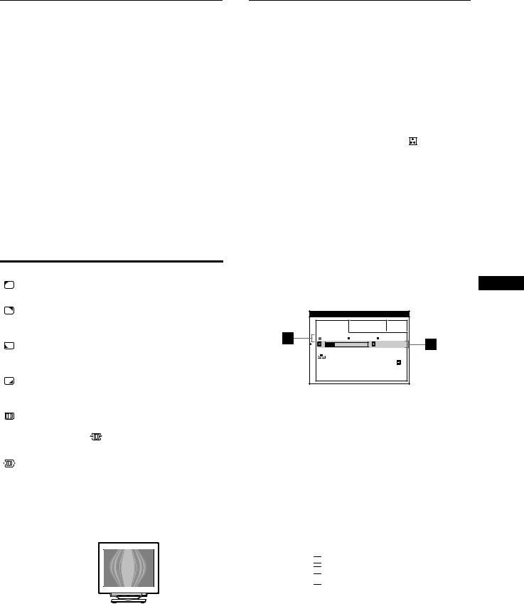
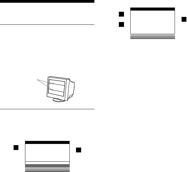
•Moire is a type of natural interference which produces soft, wavy lines on your screen. It may appear due to interference between the pattern of the picture on the screen and the phosphor pitch pattern of the monitor.
Example of moire
Note
The picture may become fuzzy when CANCEL MOIRE is set to ON.
Adjusting the color of the picture (COLOR)
The COLOR settings allow you to adjust the picture’s color temperature by changing the color level of the white color field. Colors appear reddish if the temperature is low, and bluish if the temperature is high. This adjustment is useful for matching the monitor’s color to a printed picture’s colors.
1 |
Press the center of the control button. |
|
|
The main MENU appears on the screen. |
|
2 |
Move the control button to highlight |
COLOR and |
|
press the center of the control button again. |
|
|
The COLOR menu appears on the screen. |
|
3 |
Move the control button </, to select the |
|
|
adjustment mode. |
|
|
There are three types of adjustment modes, EASY, EXPERT |
|
|
and sRGB. |
|
4 |
First move the control button m/M to select the |
|
desired adjustment item. Then move the control button </, to make the adjustment.
Adjust the selected mode according to the following
instructions.
US
EASY mode
COLOR |
|
|
EASY |
EXPERT |
s RGB |
5 0 0 0 K 6 5 0 0 K 9 3 0 0 K |
||
|
|
5 0 0 0 K |
I MAGE |
|
|
RES TORA T I ON |
ON |
|
1Move the control button m/M to select the color temperature row 1. Then move the control button </, to select a color temperature.
The preset color temperatures are 5000K, 6500K, and 9300K. Since the default setting is 9300K, the whites will change from a bluish hue to a reddish hue as the temperature is lowered to 6500K and 5000K.
2If necessary, fine tune the color temperature. Move the control button m/M to select the color temperature row 2. Then move the control button </, to fine tune the color temperature.
If you fine tune the color temperature, the new color settings
are stored in memory for each of the three color temperatures and item 1of the on-screen menu changes as follows.
•[5000K] t[ 

 1]
1]
•[6500K] t[ 

 2]
2]
•[9300K] t[ 

 3]
3]
(continued)
13
EXPERT mode
You can make additional adjustments to the color in greater detail by selecting the EXPERT mode.
COLOR |
|
|
|
EASY |
EXPERT |
s RGB |
|
5 0 0 0 K 6 5 0 0 K 9 3 0 0 K |
|||
R |
B I AS |
|
5 0 |
G |
B I AS |
|
5 0 |
B |
B I AS |
|
5 0 |
R |
GA I N |
|
5 0 |
G |
GA I N |
|
5 0 |
B |
GA I N |
|
5 0 |
1Move the control button m/M to select the color temperature row 1. Then move the control button </, to select a color temperature.
2Move the control button m/M to select the adjustment item 2. Then move the control button </, to adjust the BIAS (black level).
This adjusts the dark areas of an image.
3Move the control button m/M to select the adjustment item 3. Then move the control button </, to adjust the GAIN (white level).
This adjusts the light areas of an image.
You can adjust the R (red), G (green), B (blue) component of the input signal when making changes to items 2and 3.
If you fine tune the color temperature, the new color settings
are stored in memory for each of the three color temperatures and item 1of the on-screen menu change as follows.
•[5000K] t[ 

 1]
1]
•[6500K] t[ 

 2]
2]
•[9300K] t[ 

 3]
3]
Setting the color temperature for each of the video input connectors
You can set the fine tuning of the color temperature in EASY or EXPERT mode for each of the video input connectors (HD15 and BNC).
1Select the same adjustment mode and color temperature in the COLOR menu for both HD15 and BNC.
2Fine tune the color temperature in each menu for HD15 and BNC.
The settings are stored in memory for each of the HD15 and BNC connectors.
For information on how to select the connector, see page 8.
sRGB mode
The sRGB color setting is an industry standard color space protocol designed to correlate the displayed and printed colors of sRGB compliant computer products. To adjust the colors to the
sRGB profile, simply select the sRGB mode in the COLOR menu. However, in order to display the sRGB colors correctly (γ=2.2,
6500K), you must set your computer to the sRGB profile and adjust the brightness (  ) and contrast (6) to the numbers shown in the menu. For information on how to change the brightness
(  ) and contrast (6), see page 10.
Note
Your computer and other connected products (such as a printer), must be sRGB compliant.
COLOR
|
|
|
|
|
|
|
EASY |
|
EXPERT |
|
s RGB |
|
|
|
|
|
|
|
|
|
: 5 6 |
|
: 7 6 FOR |
|
s RGB |
|
|
I MAGE |
|
|
|
|
|
|
RES TORA T I ON |
ON |
|
||||
|
|
|
|
|
|
|
14
Restoring the color from the EASY or sRGB menus
The colors of most display monitors tend to gradually lose brilliance over several years of service. The IMAGE RESTORATION feature found in the EASY and sRGB menus allows you to restore the color to the original factory quality levels. The explanation below explains how to restore the monitor’s color from the EASY menu.
1Move the control button </, to select EASY or sRGB mode.
2First move the control button m/M to select 
(IMAGE RESTORATION). Then move the control button ,.
The picture disappears while the color is being restored (about 2 seconds). After the color is restored, the picture reappears on the screen again.
Notes
•Before using this feature, the monitor must be in normal operation mode (green power indicator on) for at least 30 minutes. If the monitor goes into power saving mode, you must return the monitor to normal operation mode and wait for 30 minutes for the monitor to be ready. You may need to adjust your computer’s power saving settings to keep the monitor in normal operation mode for the full 30 minutes. If the monitor is not ready, the following message will appear.
COLOR |
|
|
EASY |
EXPERT |
s RGB |
5 0 0 0 K 6 5 0 0 K 9 3 0 0 K |
||
|
|
5 0 0 0 K |
I MAGE |
|
|
RES TORA T I ON |
|
|
|
AVA I L AB L E |
|
|
A F T ER WARM UP |
|
•The monitor may gradually lose its ability to perform this function due to the natural aging of the picture tube.
Additional settings (OPTION)
You can manually degauss (demagnetize) the monitor, change the menu position, and lock the controls.
1Press the center of the control button.
The main MENU appears on the screen.
2Move the control button to highlight 


 OPTION and press the center of the control button again.
The OPTION menu appears on the screen.
3Move the control button m/M to select the desired adjustment item.
Adjust the selected item according to the following instructions.
Degaussing the screen
The monitor is automatically demagnetized (degaussed) when the power is turned on.
To manually degauss the monitor, first move the control button m/Mto select (DEGAUSS). Then move the control button ,.
The screen is degaussed for about 2 seconds. If a second degauss cycle is needed, allow a minimum interval of 20 minutes for the best result.
US
Changing the menu’s position
Change the menu’s position if it is blocking an image on the screen.
To change the menu’s on-screen position, first move the control button m/M to select  (OSD H POSITION) for horizontal adjustment, or
  (OSD V POSITION) for vertical adjustment. Then move the control button </, to shift the on-screen menu.
Locking the controls
To protect adjustment data by locking the controls, first move the control button m/M to select  (CONTROL LOCK). Then move the control button ,, to select ON.
Only the 1(power) switch, EXIT, and  (CONTROL LOCK) of the


 OPTION menu will operate. If any other items are selected, the
  mark appears on the screen.
To cancel the control lock
Repeat the procedure above and set  (CONTROL LOCK) to OFF.
15
Resetting the adjustments
This monitor has the following three reset methods. Use the RESET button to reset the adjustments.
RESET
Resetting a single adjustment item
Use the control button to select the adjustment item you want to reset, and press the RESET button.
Resetting all of the adjustment data for the current input signal
Press the RESET button when no menu is displayed on the screen. Note that the following items are not reset by this method:
•on-screen menu language (page 8)
•adjustment mode in the COLOR menu (EASY, EXPERT, sRGB) (page 13)
•on-screen menu position (page 15)
•control lock (page 15)
Resetting all of the adjustment data for all input signals
Press and hold the RESET button for more than two seconds.
Note
The RESET button does not function when  (CONTROL LOCK) is set to ON.
Technical Features
Preset and user modes
When the monitor receives an input signal, it automatically matches the signal to one of the factory preset modes stored in the monitor’s memory to provide a high quality picture at the center of the screen. (See Appendix for a list of the factory preset modes.) For input signals that do not match one of the factory preset modes, the digital Multiscan technology of this monitor ensures that a clear picture appears on the screen for any timing in the monitor’s frequency range (horizontal: 30 – 121 kHz, vertical: 48 – 160 Hz). If the picture is adjusted, the adjustment data is stored as a user mode and automatically recalled whenever the same input signal is received.
Note for Windows users
For Windows users, check your video board manual or the utility program which comes with your graphic board and select the highest available refresh rate to maximize monitor performance.
Power saving function
This monitor meets the power-saving guidelines set by VESA, ENERGY STAR, and NUTEK. If the monitor is connected to a computer or video graphics board that is DPMS (Display Power Management Signaling) compliant, the monitor will automatically reduce power consumption in three stages as shown below.
Power mode |
Power consumption |
1 (power) |
|
|
indicator |
|
|
|
normal |
≤ 145 W |
green |
operation |
|
|
|
|
|
1 standby |
≤ 100 W |
green and orange |
|
|
alternate |
|
|
|
2 suspend |
≤ 15 W |
green and orange |
(sleep)* |
|
alternate |
|
|
|
3 active off** |
Approx. 1 W |
orange |
(deep sleep)* |
|
|
|
|
|
power off |
0 W |
off |
|
|
|
*“Sleep” and “deep sleep” are power saving modes defined by the Environmental Protection Agency.
**When your computer enters a power saving mode, the input signal is cut and NO INPUT SIGNAL appears on the screen. After a few seconds, the monitor enters a power saving mode.
16
Troubleshooting
Before contacting technical support, refer to this section.
If thin lines appear on your screen (damper wires)
The lines you are experiencing on your screen are normal for the Trinitron monitor and are not a malfunction. These are shadows from the damper wires used to stabilize the aperture grille and are most noticeable when the screen’s background is light (usually white). The aperture grille is the essential element that makes a Trinitron picture tube unique by allowing more light to reach the screen, resulting in a brighter, more detailed picture.
Damper wires
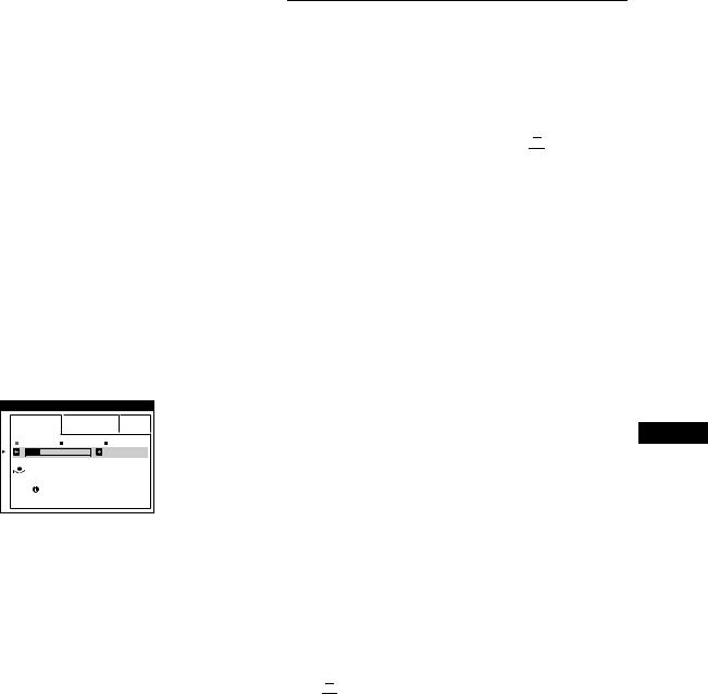
On-screen messages
If there is something wrong with the input signal, one of the following messages appears on the screen.
If NO INPUT SIGNAL appears on the screen
I NFORMA T I ON
|
MON I TOR |
I S WORK I NG |
|||
|
|
HD 1 5 |
: |
|
|
|
|
|
|
||
|
|
NO I NPUT |
S I GNA L |
|
|
WH I T E
RED
GREEN
B L UE
1The selected connector
This message shows the currently selected connector (HD15 or BNC).
2The input signal condition NO INPUT SINGAL
This indicates that no signal is input, or that no signal is input from the selected connector.
If OUT OF SCAN RANGE appears on the screen
I NFORMA T I ON
|
MON I TOR |
I S WORK I NG |
|
|||
|
|
BNC |
: 1 3 0 . 0 k H z / 7 5 H z |
|
||
|
|
|||||
|
|
|
|
|
||
|
OUT OF SCAN RANGE |
|
|
|||
|
|
|
|
|
|
|
|
CHANGE |
S I GNA L T I M I NG |
|
|||
|
|
|
|
|
|
|
|
WH I T E |
|
|
|
|
|
|
RED |
|
|
|
|
|
GREEN
B L UE
1The selected connector and the frequencies of the current input signal
This message shows the currently selected connector (HD15 or BNC). If the monitor recognizes the frequencies of the current input signal, the horizontal and vertical frequencies are also displayed.
2The input signal condition OUT OF SCAN RANGE
This indicates that the input signal is not supported by the monitor’s specifications.
3The remedies
CHANGE SIGNAL TIMING appears on the screen. If you are replacing an old monitor with this monitor, reconnect the old monitor. Then adjust the computer’s graphic board so that
the horizontal frequency is between 30 - 121 kHz, and the |
US |
vertical frequency is between 48 - 160 Hz. |
|
For more information, see “Trouble symptoms and remedies” on |
|
page 18. |
|
17

Trouble symptoms and remedies
If the problem is caused by the connected computer or other equipment, please refer to the connected equipment’s instruction manual. Use the self-diagnosis function (page 20) if the following recommendations do not resolve the problem.
Symptom |
Check these items |
|
No picture |
|
|
|
If the 1 (power) indicator is not lit |
• Check that the power cord is properly connected. |
|
|
• Check that the 1 (power) switch is in the “on” position. |
|
|
|
|
If the NO INPUT SIGNAL message |
• Check that the video signal cable is properly connected and all plugs are firmly seated in |
|
appears on the screen, or if the 1 |
their sockets. If you are using the five BNC connectors, connect them in the correct order |
|
(power) indicator is either orange or |
(from left to right: Red-Green-Blue-HD-VD) (page 6). |
|
alternating between green and |
• Check that the INPUT switch setting is correct (page 8). |
|
orange |
• Check that the HD15 video input connector’s pins are not bent or pushed in. |
|
|
xProblems caused by the connected computer or other equipment |
|
|
• The computer is in power saving mode. Try pressing any key on the computer keyboard. |
|
|
• Check that the computer’s power is “on.” |
|
|
• Check that the graphic board is completely seated in the proper bus slot. |
|
|
|
|
If the OUT OF SCAN RANGE |
xProblems caused by the connected computer or other equipment |
|
message appears on the screen |
• Check that the video frequency range is within that specified for the monitor. If you |
|
|
replaced an old monitor with this monitor, reconnect the old monitor and adjust the |
|
|
frequency range to the following. |
|
|
Horizontal: 30 – 121 kHz |
|
|
Vertical: 48 – 160 Hz |
|
|
|
|
If no message is displayed and the 1 |
• Use the Self-diagnosis function (page 20). |
|
(power) indicator is green or flashing |
|
|
orange |
|
|
|
|
|
If using Windows 95/98 |
• If you replaced an old monitor with this monitor, reconnect the old monitor and do the |
|
|
following. Install the Windows Monitor Information Disk (page 7) and select this monitor |
|
|
(“CPD-G500/G500J”) from among the Sony monitors in the Windows 95/98 monitor |
|
|
selection screen. If you choose to select “Plug and Play,” connect the monitor to the |
|
|
computer with the HD15 video signal cable. You cannot use the five BNC connectors. |
|
|
|
|
If using a Macintosh system |
• Check that the Macintosh adapter and the video signal cable are properly connected |
|
|
(page 6). |
|
|
|
Picture flickers, bounces, |
• Isolate and eliminate any potential sources of electric or magnetic fields such as other |
|
oscillates, or is scrambled |
monitors, laser printers, electric fans, fluorescent lighting, or televisions. |
|
|
|
• Move the monitor away from power lines or place a magnetic shield near the monitor. |
|
|
• Try plugging the monitor into a different AC outlet, preferably on a different circuit. |
|
|
• Try turning the monitor 90 ° to the left or right. |
xProblems caused by the connected computer or other equipment
•Check your graphics board manual for the proper monitor setting.
•Confirm that the graphics mode (VESA, Macintosh 21" Color, etc.) and the frequency of the input signal are supported by this monitor (Appendix). Even if the frequency is within the proper range, some video boards may have a sync pulse that is too narrow for the monitor to sync correctly.
•Adjust the computer’s refresh rate (vertical frequency) to obtain the best possible picture.
Picture is fuzzy |
• |
Adjust the brightness and contrast (page 10). |
|
• Degauss the monitor* (page 15). |
|
|
• |
If CANCEL MOIRE is ON, the picture may become fuzzy. Decrease the moire |
|
|
cancellation effect or set CANCEL MOIRE to OFF (page 13). |
|
|
|
18
 Loading...