


 Loading...
U |
nits |
SINAMICS
SINAMICS G120
CU250S-2 Control
 Units
Units
Compact Operati
 ng Instructions
Fundamental

 safety instructions

Scope of delivery
Installing
Commissioning
More information

1
2
3
4
5
Scan the QR code for additional information on SINAMICS G120.
05/2014
A5E32899990B AB

Legal information
Warning notice system
This manual contains notices you have to observe in order to ensure your personal safety, as well as to prevent damage to property. The notices referring to your personal safety are highlighted in the manual by a safety alert symbol, notices referring only to property damage have no safety alert symbol. These notices shown below are graded according to the degree of danger.
 DANGER
indicates that death or severe personal injury will result if proper precautions are not taken.
 WARNING
indicates that death or severe personal injury may result if proper precautions are not taken.
 CAUTION
indicates that minor personal injury can result if proper precautions are not taken.
NOTICE
indicates that property damage can result if proper precautions are not taken.
If more than one degree of danger is present, the warning notice representing the highest degree of danger will be used. A notice warning of injury to persons with a safety alert symbol may also include a warning relating to property damage.
Qualified Personnel
The product/system described in this documentation may be operated only by personnel qualified for the specific task in accordance with the relevant documentation, in particular its warning notices and safety instructions. Qualified personnel are those who, based on their training and experience, are capable of identifying risks and avoiding potential hazards when working with these products/systems.
Proper use of Siemens products
Note the following:
 WARNING
Siemens products may only be used for the applications described in the catalog and in the relevant technical documentation. If products and components from other manufacturers are used, these must be recommended or approved by Siemens. Proper transport, storage, installation, assembly, commissioning, operation and maintenance are required to ensure that the products operate safely and without any problems. The permissible ambient conditions must be complied with. The information in the relevant documentation must be observed.
Trademarks
All names identified by ® are registered trademarks of Siemens AG. The remaining trademarks in this publication may be trademarks whose use by third parties for their own purposes could violate the rights of the owner.
Disclaimer of Liability
We have reviewed the contents of this publication to ensure consistency with the hardware and software described. Since variance cannot be precluded entirely, we cannot guarantee full consistency. However, the information in this publication is reviewed regularly and any necessary corrections are included in subsequent editions.
Siemens AG |
A5E32899990B AB |
Copyright © Siemens AG 2014. |
Industry Sector |
07/2014 Subject to change |
All rights reserved |
Postfach 48 48 |
|
|
90026 NÜRNBERG |
|
|
GERMANY |
|
|

Table of contents
1 |
Fundamental safety instructions.............................................................................................................. |
4 |
|
|
1.1 |
General safety instructions ............................................................................................................ |
4 |
|
1.2 |
Industrial security ........................................................................................................................... |
5 |
2 |
Scope of delivery .................................................................................................................................... |
6 |
|
3 |
Installing |
................................................................................................................................................. |
7 |
|
3.1 |
Snapping the Control Unit onto the Power Module ........................................................................ |
7 |
|
3.2 ............................................................................................................. |
Overview of the interfaces |
8 |
|
3.3 ............................................................................................................................ |
Terminal blocks |
10 |
|
3.4 ........................................................................................................................... |
Operator panels |
14 |
4 |
Commissioning ..................................................................................................................................... |
15 |
|
|
4.1 ................................................................................................... |
Commissioning with STARTER |
15 |
|
4.2 ........................................................................................ |
Connecting the inverter to the fieldbus |
20 |
|
4.3 ................................................................................................... |
Frequently required parameters |
22 |
5 |
More information ................................................................................................................................... |
25 |
|
|
5.1 ............................................................................................................. |
Manuals for your inverter |
25 |
|
5.2 ............................................................................................................................ |
Product support |
26 |
This manual describes how you install a SINAMICS G120 converter with CU250S-2 Control Unit and commission it.
What is the meaning of the symbols in the manual?
An operating instruction starts here.
This concludes the operating instruction.
CU250S-2 Control Units |
|
Compact Operating Instructions, 05/2014, A5E32899990B AB |
3 |

1 |
Fundamental safety instructions |
1.1General safety instructions
 WARNING
Risk of death if the safety instructions and remaining risks are not carefully observed
If the safety instructions and residual risks are not observed in the associated hardware documentation, accidents involving severe injuries or death can occur.
•Observe the safety instructions given in the hardware documentation.
•Consider the residual risks for the risk evaluation.
 WARNING
Danger to life or malfunctions of the machine as a result of incorrect or changed parameterization
As a result of incorrect or changed parameterization, machines can malfunction, which in turn can lead to injuries or death.
•Protect the parameterization (parameter assignments) against unauthorized access.
•Respond to possible malfunctions by applying suitable measures (e.g. EMERGENCY STOP or EMERGENCY OFF).
|
CU250S-2 Control Units |
4 |
Compact Operating Instructions, 05/2014, A5E32899990B AB |

Fundamental safety instructions
1.2 Industrial security
1.2Industrial security
Note
Industrial security
Siemens provides products and solutions with industrial security functions that support the secure operation of plants, solutions, machines, equipment and/or networks. They are important components in a holistic industrial security concept. With this in mind, Siemens’ products and solutions undergo continuous development. Siemens recommends strongly that you regularly check for product updates.
For the secure operation of Siemens products and solutions, it is necessary to take suitable preventive action (e.g. cell protection concept) and integrate each component into a holistic, state-of-the-art industrial security concept. Third-party products that may be in use should also be considered. For more information about industrial security, visit Hotspot-Text (http://www.siemens.com/industrialsecurity).
To stay informed about product updates as they occur, sign up for a product-specific newsletter. For more information, visit Hotspot-Text (http://support.automation.siemens.com).
 WARNING
Danger as a result of unsafe operating states resulting from software manipulation
Software manipulation (e.g. by viruses, Trojan horses, malware, worms) can cause unsafe operating states to develop in your installation which can result in death, severe injuries and/or material damage.
•Keep the software up to date.
You will find relevant information and newsletters at this address (http://support.automation.siemens.com).
•Incorporate the automation and drive components into a holistic, state-of-the-art industrial security concept for the installation or machine.
You will find further information at this address (http://www.siemens.com/industrialsecurity).
•Make sure that you include all installed products into the holistic industrial security concept.
CU250S-2 Control Units |
|
Compact Operating Instructions, 05/2014, A5E32899990B AB |
5 |

2 |
Scope of delivery |
Scope of delivery
The delivery comprises at least the following components:
●A CU250S-2 Control Unit ready for operation with installed firmware.
Options for upgrading and downgrading the firmware can be found on the Internet: Firmware (http://support.automation.siemens.com/WW/news/en/67364620).
The fieldbus interface of the Control Unit depends on the order number. The order number, the designation and the version of the hardware (e.g. 02)
and firmware (e.g. 4.6) can be found on the rating plate of the Control Unit.
|
Designation |
Order number |
Fieldbus |
|
CU250S-2 |
6SL3246-0BA22-1BA0 |
USS, Modbus RTU |
|
CU250S-2 DP |
6SL3246-0BA22-1PA0 |
PROFIBUS |
|
CU250S-2 PN |
6SL3246-0BA22-1FA0 |
PROFINET, EtherNet/IP |
|
CU250S-2 CAN |
6SL3246-0BA22-1CA0 |
CANopen |
|
|
|
|
●Compact Operating Instructions in German and English
●The inverter contains open-source software (OSS). The OSS license terms are saved in the inverter.
Transferring license terms of the OSS code to a PC
Procedure
To transfer the OSS license terms from the inverter to a PC, proceed as follows:
1.Switch off the inverter power supply.
2.Insert an empty memory card into the card slot of the inverter. Also see Section:Overview of the interfaces (Page 8)
3.Switch on the inverter power supply.
4.When you have switched on the power supply, wait 30 seconds.
During this time, the inverter writes the "Read_OSS.ZIP" file onto the memory card.
5.Switch off the inverter power supply.
6.Remove the card from the inverter.
7.Use a card reader and load the file to a PC.
You have then transferred the OSS license terms from the inverter to a PC.
|
CU250S-2 Control Units |
6 |
Compact Operating Instructions, 05/2014, A5E32899990B AB |
Installing |
3 |
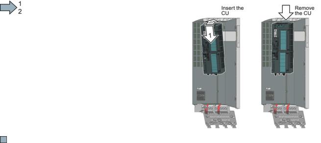
3.1Snapping the Control Unit onto the Power Module
Installing the Control Unit on an IP20 Power Module
Procedure
Proceed as follows to connect Power
Modules and Control Units:
1.Locate the lugs at the rear of the Control Unit in the matching recesses of the Power Module.
2.Mount the Control Unit onto the Power Module so that it audibly snaps into place.
The Power Module and the Control Unit are now connected with one another.
To remove the Control Unit, press on the release button on the Power Module and withdraw the Control Unit.
Permissible Power Modules
You may operate the Control Unit with the following Power Modules:
●PM240
●PM240-2
●PM250
●PM260
●PM340 1AC
CU250S-2 Control Units |
|
Compact Operating Instructions, 05/2014, A5E32899990B AB |
7 |

Installing
3.2 Overview of the interfaces
3.2Overview of the interfaces
To access the interfaces at the front of the Control Unit, you must unplug the Operator Panel (if one is being used) and open the front doors.
Terminal stripsFieldbus interface
Selecting the fieldbus address:
• PROFIBUS
• USS
• Modbus RTU
• CanOpen
Status LED
USB interface for connection to a PC
No function. Keep the switch in the "Vector" position.
Switch for analog inputs I 0/4 mA … 20 mA U -10/0 V … 10 V
Connection to the operator panelMemory card slot
|
CU250S-2 Control Units |
8 |
Compact Operating Instructions, 05/2014, A5E32899990B AB |
Loading...