


Technical documentation 03/2020
SINAMICS G120X
Available in power ratings up to 700 hp (630 kW)
usa.siemens.com/sinamics-g120x
SINAMICS G120X
An infrastructure drive for pumps, fans and compressors
Siemens introduces an exciting new addition to the existing SINAMICS product portfolio — the G120X — an “infrastructure” drive up to 700 hp (630kW), which is targeted for pump, fan and compressor applications in the water / wastewater, HVAC, irrigation / agriculture and industrial chiller and refrigeration industries.
Seamless process for higher efficiency
SINAMICS G120X is simple, seamless, costand energy-efficient, robust, reliable and fit for digitalization. It integrates easily into existing applications, works with any standard motor (induction, synchronous and synchronous reluctance) and can be configured for
cost-optimization and resource-saving operation which ultimately helps reduce total cost of ownership. SINAMICS G120X meets all the latest industry standards with regard to energy efficiency and product safety, and offers enhanced safety with SIL3-rated safety functions and up to 100kA short-circuit current rating according to new UL61800-5-1 design.
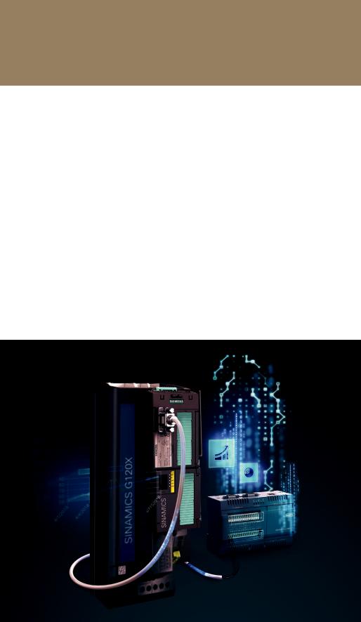
SINAMICS G120X with SINAMICS Connect 300 for MindSphere connectivity
2

Technical data |
|
|
Line voltage and output power range |
|
|
|
3AC 200V (-20%)…240V (+10%) |
1 hp…75 hp (0.75kW…55kW) |
FSA…FSF |
||
FSA…FSG |
3AC 380V (-20%)…480V (+10%) |
1 hp…400 hp (0.75kW…250kW) |
FSH, FSJ |
3AC 380V (-15%)…480V (+10%) |
400 hp…700 hp (315kW…560kW) |
|
|
|
FSD…FSG |
3AC 500V (-20%)…690V (+10%) |
4 hp…250 hp (3kW…250kW) |
FSH, FSJ |
3AC 500V (-15%)…690V (+10%) |
350 hp…700 hp (315kW…630kW) |
|
|
|
|
|
|
Output voltage |
3AC 0V….line voltage x 0.97 |
|
|
|
|
|
|
|
Input frequency |
47 Hz…63 Hz |
|
|
|
|
Output frequency |
|
|
|
0 Hz…550 Hz (depending upon the control mode) |
|
FSA…FSG |
||
|
|
|
FSH, FSJ |
0 Hz…150 Hz (depending upon the control mode) |
|
|
|
|
Fundamental power factor (Cos φ)
Efficiency class
Efficiency (η)
Motor control
Supported motor types
Degree of protection
Operating temperature
0.96…0.99
IE2 (Based on power losses according to EN 50598-2 and IEC 61800-9-2)
98%
νV/Hz control (linear, linear with flux current control / FCC, parabolic and eco mode)
νSensorless less vector control (SLVC)
νAsynchronous (induction) motor
νPermanent magnet synchronous motor (PMSM)
νSynchronous reluctance motor (SRM)
IP20 / UL Open Type
-4° F to 113° F (-20° C to 45° C) without derating
> 113° F up to 140° F (> 45° C up to 60° C) with derating
For PROFINET, EtherNet / IPTM up to 55° C (131° F) with derating
3

Overload |
|
|
|
|
|
Low Overload (LO) / Variable Torque (VT) |
110% x IL for 60s |
|
|
|
|
High Overload (HO) / Constant Torque (CT) |
150% x IH for 60s |
|
|
PROFINET, EtherNet / IPTM, USS, Modbus RTU, BACnet MS / TP, PROFIBUS DP |
|
Communication |
||
|
Hardware-based SIL3 Safe Torque Off (STO) function with on / off switch |
|
Functional safety |
||
|
Up to 100kA according to NEW UL 61800-5-1 design |
|
Short-circuit current rating (SCCR) |
||
|
|
|
Control inputs and outputs |
|
|
|
|
|
6 Digital Inputs (DI 0 … DI 5) |
24V (12–30V) electrically isolated, 4mA current, PNP / NPN switchable |
|
|
|
|
2 Digital (Relay) Outputs (DO 0…DO 1) |
Type C, 250V AC, 2A / 30V DC, 2A for resistive, inductive or capacitive load |
|
|
|
|
2 Analog Inputs (AI 0…AI 1) |
Differential input 0V… 10V or -10V … +10V: typical current drain: 0.1 mA, |
|
|
max. voltage 35V |
|
|
0/4 mA ... 20 mA: 120 Ω input resistance, voltage < 10V, current < 80 mA |
|
|
|
|
1 Analog Output (AO 0) |
Not isolated, switchable between voltage (0V… 10V) and current |
|
|
(0/4 mA ... 20 mA) via parameter setting |
|
|
|
|
1 motor temperature sensor input |
PTC, KTY, PT1000, bi-metallic switch with normally closed contact |
|
|
|
|
1 failsafe digital input |
STO — electrically isolated |
|
|
|
|
1 internal aux. supply voltage |
24V DC, max. 250 mA |
|
10V DC, max. 10 mA |
||
|
||
|
|
|
1 external aux. supply voltage |
24V DC (20.4 … 28.8V DC), current consumption 0.5A |
|
|
|
|
1 memory card slot |
For optional SD memory cards (as a backup storage device for saving of the settings |
|
|
after drive commissioning, and also for a series commissioning of a several identical |
|
|
drives via cloning of the settings) |
|
|
|
Additional control inputs and outputs (With optional I/O Extension Module)
2 Digital Inputs (DI 6…DI 7) 24V (12–30V) electrically isolated, 4mA current, PNP / NPN switchable
4 Digital (Relay) Outputs (DO 2…DO 5) 2x Type A and 2x Type C relay outputs rated 250V AC, 2A / 30V DC, 2A for resistive, inductive or capacitive load
1 Analog Input (AI 2) Analog current input (0/4 mA … 20 mA) or Temperature sensor input (Pt10000 / LG-Ni10000 / DIN-Ni1000)
1 motor temperature sensor input (AI 3) Temperature sensor input (Sensor Pt10000 / LG-Ni10000 / DIN-Ni1000)
2 Analog Output (AO 1 … AO 2) Not isolated, switchable between voltage (0V… 10V) and current (0/4 mA ... 20 mA) via parameter setting
User interface
Standard |
Intelligent Operator Panel (IOP-2) — a high-resolution graphical color keypad |
|
|
Optional |
Smart Access Module (SAM) Part number: 6SL3255-0AA00-5AA0 — a WiFi-based |
|
web server module and engineering tool for quick setup and diagnostics using |
|
a mobile device (PC, smartphone, tablet, etc.) |
|
Basic Operator Panel (BOP-2) — a basic keypad |
|
Blank (no Operator Panel / keypad) |
|
|
4
 Loading...