


MICROMASTER
Operating Instructions
Contents |
|
|
Safety Instructions .............................................................. |
2 |
|
1. |
OVERVIEW ...................................................................... |
3 |
2. |
INSTALLATION ............................................................... |
4 |
3. |
FRONT PANEL CONTROLS & BASIC OPERATION ... |
14 |
4. |
OPERATING MODES .................................................... |
17 |
5. |
SYSTEM PARAMETERS ............................................... |
20 |
6. |
FAULT CODES .............................................................. |
34 |
7. |
SPECIFICATIONS.......................................................... |
35 |
8. |
SUPPLEMENTARY INFORMATION ............................. |
37 |
© Siemens plc 1997 |
|
G85139-H1750-U049-B |
|
|
26/09/97 |
Safety Instructions
Before installing and putting this equipment into operation, please read these safety instructions and warnings carefully and all the warning labels attached to the equipment. Make sure that the warning labels are kept in a legible condition and replace missing or damaged labels.
WARNING
This equipment contains dangerous voltages and controls dangerous rotating mechanical parts. Loss of life, severe personal injury or property damage can result if the instructions contained in this manual are not followed.
Only suitable qualified personnel should work on this equipment, and only after becoming familiar with all safety notices, installation, operation and maintenance procedures contained in this manual. The successful and safe operation of this equipment is dependent upon its proper handling, installation, operation and maintenance.
∙MICROMASTERS operate at high voltages.
∙Only permanently-wired input power connections are allowed. This equipment must be grounded (IEC 536 Class 1, NEC and other applicable standards).
∙If a Residual Current-operated protective Device (RCD) is to be used, it must be an RCD type B.
∙Machines with a three phase power supply, fitted with EMC filters, must not be connected to a supply via an ELCB (Earth Leakage Circuit-Breaker - see DIN VDE 0160, section 6.5).
∙The following terminals can carry dangerous voltages even if the inverter is inoperative:
-the power supply terminals L/L1, N/L2, L3.
-the motor terminals U, V, W.
∙Only qualified personnel may connect, start the system up and repair faults. These personnel must be thoroughly acquainted with all the warnings and operating procedures contained in this manual.
∙Certain parameter settings may cause the inverter to restart automatically after an input power failure.
∙This equipment must not be used as an ‘emergency stop’ mechanism(see EN 60204, 9.2.5.4)
∙If motor thermal protection is required, then an external PTC must be used. (Refer to Section 2.3.5.)
∙Lowering the fan tray on Frame Size C MICROMASTER exposes rotating parts. Power must be isolated prior to this operation.
CAUTION
∙Children and the general public must be prevented from accessing or approaching the equipment!
∙This equipment may only be used for the purpose specified by the manufacturer. Unauthorised modifications and the use of spare parts and accessories that are not sold or recommended by the manufacturer of the equipment can cause fires, electric shocks and injuries.
∙Keep these operating instructions within easy reach and give them to all users!
European Low Voltage Directive
The MICROMASTER product range complies with the requirements of the Low Voltage Directive 73/23/EEC as amended by Directive 98/68/EEC. The units are certified for compliance with the following standards:
EN 60146-1-1 Semiconductor converters - General requirements and line commutated converters
EN 60204-1 Safety of machinery - Electrical equipment of machines
European Machinery Directive
The MICROMASTER inverter series does not fall under the scope of the Machinery Directive. However, the products have been fully evaluated for compliance with the essential Health & Safety requirements of the directive when used in a typical machine application. A Declaration of Incorporation is available on request.
European EMC Directive
When installed according to the recommendations described in this manual, the MICROMASTER fulfills all requirements of the EMC Directive as defined by the EMC Product Standard for Power Drive Systems EN61800-3.
UL and CUL listed.
ISO 9001
Siemens plc operates a quality management system which complies with the requirements of ISO 9001.
G85139-H1750-U049-B |
© Siemens plc 1997 |
26/09/97

1. OVERVIEW |
English |
1. OVERVIEW
The MICROMASTERS are a range of frequency inverters for controlling the speed of three phase AC motors. Various models are available, ranging from the compact 120 W single phase input MICROMASTER up to the 7.5 kW three phase input MICROMASTER.
The inverters are microprocessor-controlled and use flexibility. A special pulse-width modulation method extremely quiet motor operation. Inverter and motor functions.
Features:
state of the art IGBT technology for reliability and with selectable ultrasonic pulse frequency permits protection is provided by comprehensive protective
∙Easy to install, program and commission.
∙Closed loop control using a Proportional, Integral (PI) control loop function.
∙High starting torque with automatic starting boost.
∙Remote control capability via RS485 serial link using the USS protocol with the ability to control up to 31 inverters.
∙A comprehensive range of parameters is provided to enable the inverters to be configured for use in almost any application.
∙Membrane-type front panel controls for simple operation.
∙Built-in non-volatile memory for storing parameter settings.
∙Factory default parameter settings pre-programmed for European and North American requirements.
∙Output frequency (and hence motor speed) can be controlled by one of five methods:
(1)Frequency setpoint using the keypad.
(2)High resolution analogue setpoint (voltage input).
(3)External potentiometer to control motor speed.
(4)Fixed frequencies via binary inputs.
(5)Serial interface.
∙Built-in DC injection brake with special COMPOUND BRAKING.
∙Integral RFI filter on single phase input inverters (MM12 - MM300).
∙Acceleration/deceleration times with programmable smoothing.
∙Fully programmable single relay output incorporated.
∙External Options connector for optional multi-language Clear Text Display (OPM2) or optional PROFIBUS module.
∙Automatic recognition of 2, 4, 6 or 8-pole motors by software.
∙Integral software-controlled cooling fan.
∙Fast Current Limit (FCL) for reliable trip-free operation.
∙Compact design and the ability to mount inverters side by side provides greater space saving.
© Siemens plc 1997 G85139-H1750-U049-B
3 |
26/09/97 |
|

English |
2. INSTALLATION |
2. INSTALLATION
2.1 Wiring Guidelines to Minimise the Effects of EMI
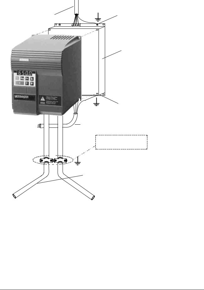
The inverters are designed to operate in an industrial environment where a high level of Electro-Magnetic Interference (EMI) can be expected. Usually, good installation practices will ensure safe and trouble-free operation. However, if problems are encountered, the following guidelines may prove useful. In particular, grounding of the system 0V at the inverter, as described below, may prove effective. Figure 1 illustrates how an RFI suppression filter should be installed.
(1)Ensure that all equipment in the cubicle is well earthed using short, thick earthing cable connected to a common star point or busbar. It is particularly important that any control equipment that is connected to the inverter (such as a PLC) is connected to the same earth or star point as the inverter via a short, thick link. Flat conductors (e.g. braids or metal brackets) are preferred as they have lower impedance at high frequencies.
The return earth from motors controlled by the inverters should be connected directly to the earth connection (PE) on the associated inverter.
(2)Wherever possible, use screened leads for connections to the control circuitry. Terminate the ends of the cable neatly, ensuring that unscreened wires are as short as possible. Use cable glands whenever possible.
(3)Separate the control cables from the power connections as much as possible, using separate trunking, etc. If control and power cables cross, arrange the cables so that they cross at 90° if possible.
(4)Ensure that contactors in the cubicle are suppressed, either with R-C suppressors for AC contactors or ‘flywheel’ diodes for DC contactors,fitted to the coils. Varistor suppressors are also effective. This is particularly important if the contactors are controlled from the relay on the inverter.
(5)Use screened or armoured cables for the motor connections and ground the screen at both ends via the cable glands.
(6)If the drive is to be operated in an Electro-magnetic noise-sensitive environment, the RFI footprint filter kit should be used to reduce the conducted and radiated interference from the inverter. For optimum performance, there should be a good conductive bond between filter and metal mounting plate.
On no account must safety regulations be compromised when installing inverters!
G85139-H1750-U049-B |
© Siemens plc 1997 |
26/09/97 |
4 |
|
2. INSTALLATION |
English |
MAINS POWER
CABLE
Connect to Mains and
PE terminals on Inverter
CONTROL
CABLE
EARTH STUD
FILTER UNIT
Note: There must be a good conductive bond between filter and metal panel.
EARTH STUD (under)
SCREENED
CABLE
When cable glands cannot be used, terminate screen to metal panel by removing cable sheath.
SCREENED |
When attempting to meet specific EMC limits by using a filter, |
|||
the following points must be observed: |
||||
CABLE |
||||
|
|
(1) |
All cables to and from the inverter (including control |
|
|
|
|||
|
|
|
cables) must be screened using suitable glands. |
|
|
|
(2) |
The control cable must be kept separate from the motor |
|
|
|
|||
|
|
|
and mains cables. |
|
|
MOTOR * Note: Screen must be terminated |
|||
|
CABLE * |
|
at the motor. |
|
Figure 1: Example of an RFI Suppression Filter Installation
© Siemens plc 1997 G85139-H1750-U049-B
5 |
26/09/97 |
|
English |
2. INSTALLATION |
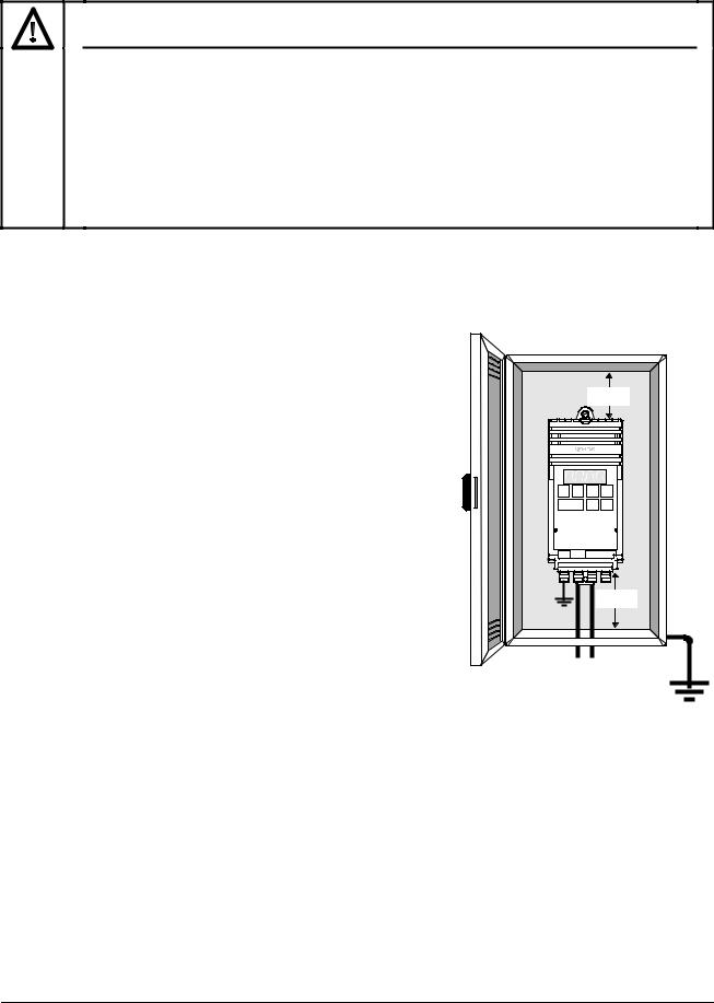
2.2 Mechanical Installation
WARNING
THIS EQUIPMENT MUST BE EARTHED.
To guarantee the safe operation of the equipment it must be installed and commissioned properly by qualified personnel in compliance with the warnings laid down in these operating instructions.
Take particular note of the general and regional installation and safety regulations regarding work on dangerous voltage installations (e.g. VDE), as well as the relevant regulations regarding the correct use of tools and personal protective gear.
The mains input and motor terminals can carry dangerous voltages even if the inverter is inoperative. Use insulated screwdrivers only on these terminal blocks.
Environmental Requirements
Hazard
Temperature
Altitude
Shock
Vibration
Electro-Magnetic
Radiation
Atmospheric
Pollution
Water
Overheating
Notes
Min. = 0°C
Max. = 50°C
If the Inverter is to be installed at an altitude > 1000 m, derating will be required.(Refer to DA 64 Catalogue).
Do not drop the inverter or expose to sudden shock.
Do not install the inverter in an area where it is likely to be exposed to constant vibration.
Do not install the inverter near sources of electro-magnetic radiation.
Do not install the inverter in an environment which contains atmospheric pollutants such as dust, corrosive gases, etc.
Take care to site the inverter away from potential water hazards. e.g. Do not install the inverter beneath pipes that are subject to condensation.
Ensure that the inverter’s air vents are not obstructed.
Make sure that there is an adequate air-flow through the cabinet, as follows:
1.Using the formula below, calculate the airflow required.
Air-flow (m3 / hr) = (Dissipated Watts / T) x 3.1 2. Install cabinet cooling fan(s) if necessary,
Note:
Typical dissipation (Watts) = 3% of inverter rating.
T = Allowable temperature rise within cabinet in °C.
3.1 = Specific heat of air at sea level.
Ideal Installation
100 mm |
160 mm |
G85139-H1750-U049-B |
© Siemens plc 1997 |
26/09/97 |
6 |
|
2. INSTALLATION |
English |
W1 |
F
|
|
|
|
|
|
|
|
|
|
|
DIN Rail |
|
|
|
|
|
|
|
|
|
|
|
|
|
|
|
|
|
|
|
|
|
|
|
|
|
|
|
|
|
|
||
|
|
|
|
|
|
|
|
|
|
|
|
H2 |
|
|
|
|
|
|
|
|
|
H1 |
|
|
|
|
|
H |
|
H2 |
H1 |
|
Depth D |
|
H |
||||||||
|
|
|
|
|
|
|
|
|
|
||||||||||||
|
|
Depth D |
|
|
|
|
|
|
|
|
|
|
|
|
|||||||
|
|
|
|
|
|
|
|
|
|
|
|
|
|
|
|||||||
|
|
|
|
|
|
|
|
|
|
|
|
|
|
|
|
|
|
|
|
|
|
|
|
|
|
|
|
|
|
|
|
|
|
|
|
|
|
|
|
|
|
|
|
|
|
|
|
|
|
|
|
|
|
|
|
|
|
|
|
|
|
|
|
|
|
|
|
|
|
|
|
|
|
|
|
|
|
|
|
|
|
|
|
|
|
|
|
|
|
|
|
|
|
|
|
|
|
|
|
|
|
|
|
|
|
|
|
|
|
W |
W |
|


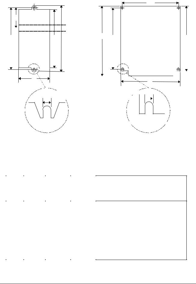
= 4.5 mm
Tightening Torque (with washers fitted)
2.5Nm Frame size A and B
3.0Nm Frame size C
= 4.8 mm (B) 
 = 5.6 mm (C)
2 bolts M4 |
Frame size B: |
Frame size C: |
|
4 bolts M4 |
4 bolts M5 |
||
2 nuts M4 |
|||
4 nuts M4 |
4 nuts M5 |
||
2 washers M4 |
|||
4 washers M4 |
4 washers M5 |
||
|
|||
Frame Size A |
Frame Sizes B and C |
||
|
MMxxx |
MMxxx/2 |
MMxxx/3 |
Model |
1 AC 230 V |
1/3 AC 230 V |
3 AC 380 - |
|
Class A |
Without |
500 V |
|
Filter |
Filter |
Without |
|
|
|
Filter |
MM12 |
A |
A |
- |
MM25 |
A |
A |
- |
MM37 |
A |
A |
A |
MM55 |
A |
A |
A |
MM75 |
A |
A |
A |
MM110 |
B |
B |
A |
MM150 |
B |
B |
A |
MM220 |
C |
C |
B |
MM300 |
C |
C |
B |
MM400 |
- |
C |
C |
MM550 |
- |
- |
C |
MM750 |
- |
- |
C |
Frame Sizes
(all measurements in mm)
|
H |
|
W |
D |
H1 |
H2 |
W1 |
F |
A = 147 |
x 73 |
x 141 |
160 |
175 |
- |
55 |
||
B = |
184 |
x |
149 |
x 172 |
174 |
184 |
138 |
- |
C = |
215 |
x |
185 |
x 195 |
204 |
232 |
174 |
- |
Figure 2: Mechanical Installation Diagram
© Siemens plc 1997 G85139-H1750-U049-B
7 |
26/09/97 |
|
English |
2. INSTALLATION |
2.3 Electrical Installation
The electrical connectors on the MICROMASTER are shown in Figure 3. Connect the cables to the power and control terminal blocks in accordance with the information supplied in sections 2.3.1 - 2.3.4. Ensure that the leads are connected correctly and the equipment is properly earthed as shown in Figure 3.
CAUTION
The control, power supply and motor leads must be laid separately. They must not be fed through the same cable conduit/trunking.
Use screened cable for the control lead. Use Class 1 60/75oC copper wire only (for UL compliance). Tightening torque for the power (mains input and motor) terminals is 1.1 Nm.
To tighten up the power/motor terminal screws use a 4 - 5 mm cross-tip screwdriver.
2.3.1 Power and Motor Connections - Frame Size A
Ensure that the power source supplies the correct voltage and is designed for the necessary current (see section 7). Ensure that the appropriate circuit-breakers/fuses with the specified current rating are connected between the power supply and inverter (see section 7).
Connect the power and motor connections as shown in Figure 3.
WARNING
Isolate the supply before making or changing connections.
Ensure that the motor is configured for the correct supply voltage. Single/three phase 230 V
MICROMASTERS must not be connected to a 400 V three phase supply.
When synchronous machines are connected or when coupling several motors in parallel, the inverter must be operated with voltage/frequency control characteristic (P077= 0 or 2).
G85139-H1750-U049-B |
© Siemens plc 1997 |
26/09/97 |
8 |
|

2. INSTALLATION |
English |
Control
Terminals
PE L/L1 N/L2 L3
Mains Input
Terminals
PE
U V W
Motor Terminals
L3
L2
L1
N
|
|
FILTER |
|
|
MOTOR |
FUSES |
CONTACTOR |
(Class B only) |
MICROMASTER |
||
|
|
||||
|
|
|
L |
U |
U |
|
|
|
|
||
|
|
|
|
V |
V |
|
|
|
|
|
|
|
|
|
N |
W |
W |
|
|
|
|
||
|
PE |
PE |
|
PE |
|
SINGLE PHASE
|
L3 |
TYPICAL INSTALLATION |
|
|
|
|
|
||
|
L2 |
|
|
|
|
L1 |
|
|
|
FUSES |
CONTACTOR |
FILTER |
|
MOTOR |
MICROMASTER |
||||
|
|
|
L3 |
U |
|
|
|
U |
|
|
|
|
L2 |
V |
|
|
|
V |
|
|
|
|
L1 |
W |
|
|
|
W |
|
|
PE |
PE |
|
PE |
THREE PHASE
Figure 3: |
Power Connections |
|
|
|
|
© Siemens plc 1997 |
|
G85139-H1750-U049-B |
|
9 |
26/09/97 |
|
|
English |
2. INSTALLATION |
2.3.2 Power and Motor Connections - Frame Size B
The terminal arrangement for frame size B is identical to frame size A (see Figure 3). However, before the wires can be connected to the terminal blocks, you must lower the terminal access panel and secure the cables to the gland plate.
Refer to Figures 3 and 4. Proceed as follows:
1.Insert the blade of a small screwdriver into slot A on the side of the inverter and press in the direction of the arrow. At the same time, apply finger pressure to clip B on the other side of the access panel and press in the direction of the arrow.
This will release the access panel, which will then swing down on its rear-mounted hinges.
2.Remove the gland plate by applying pressure to release clips C and D in the direction of the arrows.
3.Secure each cable to the correct hole in the gland plate, ensuring that the exposed wires are long enough to reach the terminal blocks.
4.Before refitting the gland plate, feed the control wires (if used) through hole 1 and the mains input and motor wires through hole 2. IT IS MOST IMPORTANT THAT THE MOTOR AND CONTROL WIRES ARE KEPT APART.
5.Refit the gland plate. Ensure that the release clips snap into position.
6.Connect the wires to the terminal blocks as shown in Figure 3. (See section 2.3.4 for information about connecting the control wires.)
7.Close the terminal access panel.
A
 B
B
E
C F
D
G
A & B: Terminal cover release tabs
C & D: Gland plate release tabs
E:Control cable input (16.2 mm diameter; accepts cables up to 10 mm diameter)
F:Mains cable input (22.8 mm diameter; accepts cables up to 14.5 mm diameter)
G:Motor cable input (22.8 mm diameter; accepts cables up to 14.5 mm diameter)
Figure 4: Power Connections Access Diagram - Frame Size B
G85139-H1750-U049-B |
© Siemens plc 1997 |
26/09/97 |
10 |
|
2. INSTALLATION |
English |
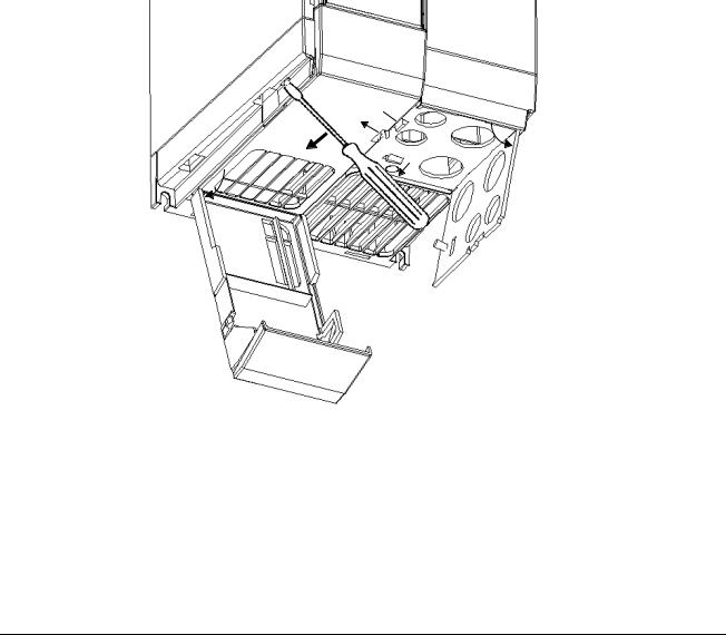
2.3.3 Power and Motor Connections - Frame Size C
The terminal arrangement for frame size C is identical to frame size A (see Figure 3). However, before the wires can be connected to the terminal blocks, you must lower the fan housing and secure the cables to the gland plate.
Refer to Figure 5 and proceed as follows:
1.While supporting the fan housing with one hand, insert the blade of a screwdriver into slot A on the underside of the inverter and press upwards to release the securing tab. Lower the fan housing, allowing it to swing out to the right on its side-mounted hinges.
2.Applying pressure to the gland plate release clips B and C in the direction of the arrows. Swing the plate out to the left on its side-mounted hinges,
3.Secure each cable to the correct hole in the gland plate, ensuring that the exposed wires are long enough to reach the terminal blocks.
4.Connect the wires to the terminal blocks as shown in Figure 3. (See section 2.3.4 for information about connecting the control wires.) IT IS MOST IMPORTANT THAT THE MOTOR AND CONTROL WIRES ARE KEPT APART.
5.Swing the gland plate back into the base of the inverter. Ensure that the release clips snap into position.
6.Swing the fan housing back into the base of the inverter.
D
E  B
B
F  A
A
C 
A: Fan housing release tab
B & C: Gland plate release tabs
D:Control cable input (16.2 mm diameter; accepts cables up to 10 mm diameter)
E:Mains cable input (22.8 mm diameter; accepts cables up to 14.5 mm diameter)
F:Motor cable input (22.8 mm diameter; accepts cables up to 14.5 mm diameter)
Figure 5: Power Connections Access Diagram - Frame Size C
© Siemens plc 1997 G85139-H1750-U049-B
11 |
26/09/97 |
|
English |
2. INSTALLATION |
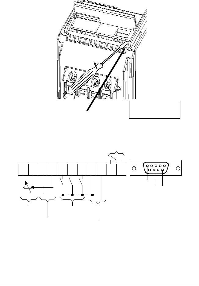
2.3.4 Control Connections
|
|
|
|
|
|
|
|
|
|
Insert |
small |
blade |
screwdriver |
|
|
|
|
|
|
|
|
|
|
(max. 3.5 mm) as shown while |
|||
|
|
|
|
|
|
|
|
|
|
inserting control wire from below. |
|||
|
|
|
|
|
|
|
|
|
Output Relay |
|
|
|
|
|
|
|
|
|
|
|
|
|
(normally open) |
|
|
|
|
|
|
|
|
|
|
|
|
max. 0.4 A / 110 V AC |
|
|
|
||
|
|
|
|
|
|
|
|
|
1 A / 30 V DC |
|
|
|
|
|
|
|
|
|
|
|
|
|
(resistive rating) |
|
|
|
|
P10+ |
0V |
AIN+ |
AIN- |
DIN1 |
DIN2 |
DIN3 |
P15+ |
0V |
|
|
|
|
|
|
|
|
|
|
|
|
|
|
|
|
5 |
|
1 |
1 |
2 |
3 |
4 |
5 |
6 |
7 |
8 |
9 |
10 |
11 |
9 |
|
6 |
|
|
|
|
|
|
|
|
|
RL1B |
RL1C |
0V |
P+ |
|
|
|
|
|
|
|
|
|
|
(NO) |
(COM) |
|
||
|
|
|
|
|
|
|
|
|
|
N- |
5V |
||
|
|
|
|
|
|
|
|
|
|
|
|
||
|
|
|
|
|
|
|
|
|
|
|
|
(max.250 mA) |
|
|
|
|
|
|
|
|
|
|
|
|
Front Panel |
||
Power Supply |
|
|
Digital Inputs |
|
|
|
|
RS485 D-type |
|||||
(+10 V, max. 10 mA) |
|
(7.5 - 33 V, max. 5 mA) |
|
|
|
|
|
|
|
||||
|
|
Analogue Input |
|
|
Power Supply |
|
|
|
|
|
|||
|
|
(0/2 - 10 V) |
|
|
|
|
|
|
|
|
|||
|
|
|
|
|
|
for |
|
|
|
|
|
||
|
(input impedance = |
70 kΩ) |
|
|
|
|
|
|
|
|
|||
|
|
|
PI Feedback |
|
|
|
|
|
|||||
|
|
|
|
|
|
|
|
|
|
|
|
||
Transducer or other load
(+15 V, max. 50 mA)
Control Terminal Block
Figure 6: Control Connections
G85139-H1750-U049-B |
© Siemens plc 1997 |
26/09/97 |
12 |
|
2. INSTALLATION |
English |
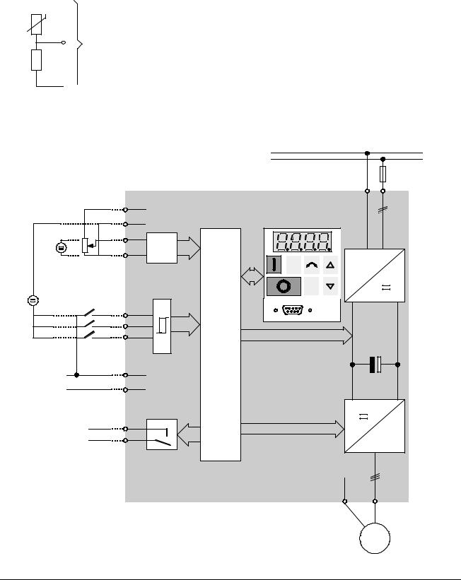
2.3.5 Motor Overload Protection
When operated below rated speed, the cooling effect of fans fitted to the motor shaft is reduced. Consequentially, most motors require de-rating for continuous operation at low frequencies. To ensure that motors are protected against overheating under these conditions, a PTC temperature sensor must be fitted to the motor and connected to the inverter control terminals as shown in Figure 7.
Note: To enable the trip function, set parameter P051, P052 or P053 =19.

 8
8
MOTOR
PTC
7
Inverter Control
Terminals
1kΩ
 9
9 
Figure 7: Motor Overload PTC Connection
2.3.6 Block Diagram |
|
|
|
|
|
|
|
|
|
|
|
PE |
|
|
|
|
|
|
1/3 AC 230 V |
|
|
|
|
|
|
3 AC 380 - 500 V |
SI |
|
³ 4.7 kW |
|
+10V |
PE |
L/L1, N/L2 |
|
|
|
|
1 |
|
or |
|
|
|
|
|
|
L/L1, N/L2, L3 |
|
|
|
|
|
0V |
|
|
V: 0 - 10 V |
|
|
2 |
|
|
|
OR |
AIN+ |
|
|
|
||
2 - 10 V |
|
|
|
|
||
|
|
AIN- |
3 |
AD |
|
|
|
|
|
|
|
||
|
|
|
|
|
|
|
|
|
|
4 |
Jog |
~ |
|
|
|
|
|
|
||
|
|
|
|
|
|
|
– |
|
|
|
|
P |
|
|
|
|
|
|
|
|
24 V |
|
|
|
|
|
|
+ |
|
DIN1 |
|
|
RS485 |
|
|
|
DIN2 |
5 |
|
|
|
|
|
|
|
|
|
|
|
|
DIN3 |
6 |
|
|
|
|
|
|
|
|
|
|
OR |
|
|
7 |
CPU |
|
|
Power Supply for |
|
|
|
+15V |
|
|
PI Feedback |
|
|
8 |
|
|
|
|
|
|
|
|
||
Transducer |
|
|
|
0V |
|
|
or other load. |
|
|
9 |
|
|
|
|
|
|
|
|
||
|
|
|
|
|
|
|
|
RL1 |
RL1B |
10 |
|
|
3 ~ |
|
|
RL1C |
11 |
|
|
|
PE U, V, W
|
|
M |
Figure 8: Block Diagram |
|
|
© Siemens plc 1997 |
|
G85139-H1750-U049-B |
|
13 |
26/09/97 |
|
|
 Loading...