


SINAMICS G120
Control Units CU240S
Getting Started
FW 3.2
10/2008
A5E01301803B AC
Additional Documentation Support |
1 |
|
|
Warnings and Cautions |
2 |
|
|
Installation |
3 |
|
|
Check List |
4 |
|
|
Commissioning |
5 |
|
|
Technical data |
6 |
|
|
Diagnostics |
A |
Legal information - Warning notice system
This manual contains notices you have to observe in order to ensure your personal safety, as well as to prevent damage to property. The notices referring to your personal safety are highlighted in the manual by a safety alert symbol, notices referring only to property damage have no safety alert symbol. If more than one degree of danger is present, the warning notice representing the highest degree of danger will be used. A notice warning of injury to persons with a safety alert symbol may also include a warning relating to property damage.
Qualified Personnel
The device/system may only be set up and used in conjunction with this documentation. Commissioning and operation of a device/system may only be performed by qualified personnel. Within the context of the safety notes in this documentation qualified persons are defined as persons who are authorized to commission, ground and label devices, systems and circuits in accordance with established safety practices and standards.
Proper use of Siemens products: note the following:
 WARNING
Siemens products may only be used for the applications described in the catalog and in the relevant technical documentation. If products and components from other manufacturers are used, these must be recommended or approved by Siemens. Proper transport, storage, installation, assembly, commissioning, operation and maintenance are required to ensure that the products operate safely and without any problems. The permissible ambient conditions must be adhered to. The information in the relevant documentation must be observed.
Disclaimer of Liability
We have reviewed the contents of this publication to ensure consistency with the hardware and software described. Since variance cannot be precluded entirely, we cannot guarantee full consistency. However, the information in this publication is reviewed regularly and any necessary corrections are included in subsequent editions.
Siemens AG |
A5E01301803B AC |
Copyright © Siemens AG 2008. |
Industry Sector |
10/2008 |
Technical data subject to |
Postfach 48 48 |
|
change |
90026 NÜRNBERG |
|
|
GERMANY |
|
|
Table of contents
1 |
Additional Documentation Support............................................................................. |
4 |
|
2 |
Warnings and Cautions............................................................................................. |
5 |
|
3 |
Installation................................................................................................................ |
7 |
|
|
3.1 |
Installing the Control Unit (all variants).................................................................. |
7 |
|
3.2 |
Terminals ............................................................................................................ |
12 |
|
3.3 |
SUB D connector for RS485 interface................................................................. |
13 |
|
3.4 |
Connecting the PROFIBUS DP........................................................................... |
15 |
|
3.5 |
Connecting a CU240S PN / CU240S PN-F via PROFINET................................. |
18 |
4 |
Check List................................................................................................................ |
21 |
|
5 |
Commissioning........................................................................................................ |
22 |
|
|
5.1 |
Create a STARTER Project................................................................................. |
23 |
|
5.2 |
Going Online with the Inverter............................................................................. |
27 |
|
5.3 |
Start Commissioning........................................................................................... |
28 |
|
5.4 |
Factory reset....................................................................................................... |
37 |
6 |
Technical data ......................................................................................................... |
38 |
|
A |
Diagnostics.............................................................................................................. |
39 |
|
Control Units CU240S |
3 |
Getting Started, 10/2008, A5E01301803B AC |
1Additional Documentation Support
SD Manual Collection and on-line documentation
SD Manual Collection
The SD Manual Collection is a complete collection of all Standard Drives documentation across the entire range of Standard Drives products, including Inverters, Motors and Geared-Motors. It is available to order as a DVD which runs in its own java-driven HTML interface.
The order number for the SD Manual Collection is: 6SL3298-0CA00-0MG0
On-line documentation
All Standard Drives documentation is available on-line at the following site: http://support.automation.siemens.com/ww/view/en/4000024
All documents are available for download, including Operating Instructions and Parameter Lists.
Device description files (GSD)
The device description files (GSD) are used to integrated an Inverter into a higher level control device, for example, SIMATIC S7. The required GSD files can be downloaded from the internet at the following site:
http://support.automation.siemens.com/www/view/en/23450835
4 |
Control Units CU240S |
Getting Started, 10/2008, A5E01301803B AC |

2Warnings and Cautions
General
 WARNING
This equipment contains dangerous voltages and controls potentially dangerous rotating mechanical parts. Non-compliance with the Warnings or failure to follow the instructions contained in this manual can result in loss of life, severe personal injury or serious damage to property.
Only suitable qualified personnel should work on this equipment, and only after becoming familiar with all safety notices, installation, operation and maintenance procedures contained in this instruction. The successful and safe operation of this equipment is dependent upon its proper handling, installation, operation and maintenance.
The power supply, DC and motor terminals, the brake and thermistor cables can carry dangerous voltages even if the inverter is inoperative. Wait at least five minutes to allow the unit to discharge after switching off the line supply before carrying out any installation work. It is strictly prohibited for any mains disconnection to be performed on the motor-side of the system; any disconnection of the mains must be performed on the mains-side of the Inverter.
When connecting the line supply to the Inverter, make sure that the terminal case of the motor is closed. When changing from the ON to OFF-state of an operation if an LED or other similar display is not lit or active; this does not indicate that the unit is switched-off or powered-down.
The inverter must always be grounded. Isolate the line supply before making or changing connections to the unit. Ensure that the inverter is configured for the correct supply voltage. The inverter must not be connected to a higher voltage supply.
Take particular notice of the general and regional installation and safety regulations regarding work on dangerous voltage installation (e.g. EN 50178) as well as the relevant regulations regarding the correct use of tools and personal protective equipment (PPE).
Control Units CU240S |
5 |
Getting Started, 10/2008, A5E01301803B AC |

Warnings and Cautions
 CAUTION
Children and the general public must be prevented from accessing or approaching the equipment!
This equipment may only be used for the purpose specified by the manufacturer. Unauthorized modifications and the use of spare parts and accessories that are not sold or recommended by the manufacturer of the equipment can cause fires, electric shocks and injuries.
NOTICE
Keep these instructions within easy reach of the equipment and make them available to all users.
Whenever measuring or testing has to be performed on live equipment, the regulations of Safety Code BGV A2 must be observed, in particular § 8 "Permissible Deviations when Working on Live Parts". Suitable electronic tools should be used.
Before installing and commissioning, please read the safety instructions and warnings carefully and all the warning labels attached to the equipment. Make sure that the warning labels are kept in a legible condition and replace missing or damaged labels.
Ensure that the appropriate circuit-breakers/fuses with the specified current rating are connected between the power supply and the inverter.
These instructions assume that the user is fully conversant with the use of the following technologies:
-PLCs
-The commissioning software STARTER
-PROFIdrive profiles and protocols.
The commissioning procedure outlined in this manual is for Standard Inverters only - Fail-safe commissioning is covered in the Operating Instructions.
6 |
Control Units CU240S |
Getting Started, 10/2008, A5E01301803B AC |
3Installation
Command and setpoint sources
Control Unit CU240S
The inverter is controlled and monitored per default via terminals. Control Unit CU240S DP / CU240S DP-F
The inverter is controlled and monitored per default via the PROFIBUS DP interface. Control Unit CU240S PN / CU240S PN-F
The inverter is controlled and monitored per default via the PROFINET interface.
Note
The command and setpoint sources can be changed in the commissioning procedure or via Parameters P0700 and P1000.
3.1Installing the Control Unit (all variants)
Description
The CU controls the functions of the inverter. It cannot be used without a Power Module (PM), also the PM cannot be used without a CU. The CU as well as the PM are IP20 rated.
 WARNING
An inverter can be switched on unintentionally if the installation is not performed correctly. The inverter must be started-up by personnel who are qualified and trained in installing systems of this type.
Control Units CU240S |
7 |
Getting Started, 10/2008, A5E01301803B AC |
Installation
SINAMICS G120 Control Units general layout
00& VORW
*HQHUDO , 2 ',3 VZLWFKHV
|
P$ |
P$ |
|
|
|
|
|
21 |
|
|
9(QFRGHU 6XSSO\ |
9(QFRGHU 6XSSO\ |
|
|
|
|
$, |
$, |
(QFRGHU$ 7HUPLQDWLRQ |
(QFRGHU% 7HUPLQDWLRQ |
(QFRGHU= 7HUPLQDWLRQ |
||
2)) |
|
|
|
|
|
|
|
|
|
|
|
|
|
|
|
9 |
9 |
|
|
|
|
|
|
2SWLRQ SRUW
6WDWXV /('VVHH OLVW EHORZ
'2 '2 '2 '2 '2 '2 '2 '2 |
(1& (1& (1& (1& (1& (1& |
||||||||||||
1& |
12 &20 12 &20 1& |
12 &20 |
$3 |
$1 |
%3 |
%1 |
=3 |
=1 |
|||||
|
|
|
|
|
|
|
|
|
|
|
|
|
|
|
|
|
|
|
|
|
|
|
(1& 8 9 8 9 |
||
', |
', |
', |
', |
', |
', |
', ', ', |
6833/< |
|
|||
|
|
|
|
|
|
|
|
|
|
|
|
$, |
$, |
$2 |
$2 |
$, |
$, |
$2 |
$2 |
9 9 |
|
|
37& 37& |
||
|
|
|
|
|
|
|
|
,1 |
,1 |
9 |
9 |
|
|
|
|
|
|
|
|
|
|
|
|
|
|
|
|
&RQWURO WHUPLQDOVOD\RXW GHSHQGHQW RQ &8 W\SH
352),%86 DGGUHVV ',3 VZLWFKHV&8 6 '3 DQG &8 6 '3 ) RQO\
QR IXQFWLRQ |
|
|
|
|
|
|
|
|
|
|
|
|||
%LW |
|
|
|
|
|
|
|
|
|
|
|
|||
%LW |
|
|
|
|
|
|
|
|
|
|
|
|||
%LW |
|
|
|
|
|
|
|
|
|
|
|
|||
%LW |
|
|
|
|
|
|
|
|
|
|
|
|||
%LW |
|
|
|
|
%LW |
|
|
|
|
|
||||
|
|
|
||
%LW |
|
|
|
|
|
||||
|
|
|
||
|
|
|
|
|
|
|
21 |
|
|
|
|
%XV WHUPLQDWLRQ VZLWFK |
|
|
|
&RPPXQLFDWLRQV LQWHUIDFH |
|
|
|
|
&8 6 RQO\ |
VHH GHWDLOV EHORZ |
|
|
6WDWXV /('V
&8 6 |
|
|
|
|
|
|
|
|
|
|
|
|
|
|
|
|
|
|
|
|
|
|
|
|
|
|
|
|
&8 6 '3 |
|
|
|
|
|
|
|||
|
|
|
|
|
|
|
|
|
|
|
|
|
&8 6 '3 )
&8 6 31
&8 6 31 )
&RPPXQLFDWLRQV LQWHUIDFHV
&8 6 |
|
|
|
|
&8 6 '3 |
5 4 |
3 |
2 |
1 |
&8 6 '3 ) |
9 |
8 |
7 |
6 |
56 352),%86
&8 6 31&8 6 31 )352),1(7
8 |
Control Units CU240S |
Getting Started, 10/2008, A5E01301803B AC |

Installation
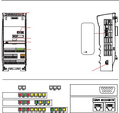
Interfaces of the CU240S Control Units.
The interfaces are shown in the figure below. Common Interfaces
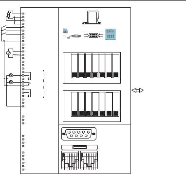
The CU240S Control Units have a number of interfaces such as terminals, general I/O DIP switches or MMC interface and Option Port in common.
Different Interfaces
●9-pole SUB D connector as communication interface for
–CU240S (USS via RS485),
–CU240S DP (PROFIBUS DP)
–CU240S DP-F (PROFIBUS DP)
●Failsafe terminals for
–CU240S DP-F: Two paired fail-safe digital inputs,
–CU240S PN-F: marked with a "*" in the figure
●DIP switches to set the PROFIBUS address
–CU240S DP (PROFIBUS DP)
–CU240S DP-F (PROFIBUS DP)
●RJ45 connectors as communication interface
–CU240S PN: Two connectors
–CU240S PN-F: Two connectors
Control Units CU240S |
9 |
Getting Started, 10/2008, A5E01301803B AC |
Installation
|
9 |
|
|
|
9 |
|
|
|
$, |
|
|
|
$, |
|
|
|
', |
|
|
|
', |
|
|
|
', |
|
|
|
', |
|
|
|
8 9 )',$ |
||
|
$, |
|
|
|
$, |
|
|
|
$2 |
|
|
|
$2 |
|
|
|
37& |
|
|
|
37& |
|
|
|
', |
|
|
|
', |
|
|
|
1& |
|
|
|
|
|
|
|
12 |
'2 |
|
|
&20 |
|
|
|
|
||
|
12 |
|
|
'2 |
|
||
|
&20 |
|
|
|
1& |
|
|
|
|
|
|
|
12 |
'2 |
|
|
&20 |
|
|
|
|
||
|
$2 |
|
|
|
$2 |
|
|
|
8 9 |
|
|
|
9 |
|
|
|
9 |
|
|
|
(1& |
|
|
|
6XSSO\ |
|
|
|
', )',$ |
||
|
', )', % |
||
|
', )',$ |
||
|
)', % |
||
|
(1&$3 |
|
|
|
(1&$1 |
|
|
|
(1& %3 |
|
|
|
(1& %1 |
|
|
|
(1& =3 |
|
|
|
(1& =1 |
|
|
)DLOVDIH YHUVLRQV LQ EUDFNHWV
|
|
00& |
|
|
|
|
|
|
2SWLRQ 3RUW |
|
|
|
|
3& &RQQHFWLRQ .LW |
|
|
%23 |
|
||
RSWLRQDO |
|
|
|
%DVLF 2SHUDWRU 3DQHO |
||
*HQHUDO , 2 ',3 VZLWFKHV |
|
|
|
|
||
21 |
|
|
|
|
|
|
$, |
$, |
9(QFRGHU VXSSO\ |
9(QFRGHU VXSSO\ |
(QFRGHU$ WHUPLQDWLRQ |
(QFRGHU% WHUPLQDWLRQ |
(QFRGHU= WHUPLQDWLRQ |
|
|
|
|
|
|
|
2)) |
|
|
|
|
|
|
352),%86$GGUHVV ',3 VZLWFK RQO\ &8 6 '3 '3 ) |
||||||
21 |
|
|
|
|
|
|
|
|
|
|
|
|
|
%LW |
%LW |
%LW |
%LW |
%LW |
%LW |
%LW |
|
|
|
|
|
|
|
2)) |
|
|
|
|
|
|
|
|
|
|
&8 6 |
|
|
|
|
|
|
|
||
|
|
|
|
&8 6 '3 |
||
|
|
|
|
|
|
|
|
|
|
|
&8 6 '3 ) |
||
; 3 |
|
; 3 |
|
|
|
|
|
|
|
|
&8 6 31 |
||
|
|
|
|
&8 6 31 ) |
||
|
|
|
|
|
||
YLD 30 ,)
3RZHU0RGXOH
10 |
Control Units CU240S |
Getting Started, 10/2008, A5E01301803B AC |

Installation
Fitting the Control Unit to the Power Module
The Control Unit is snapped onto the Power Module as shown in the figure below. To disconnect the CU push the release button on top of the PM.
The process of fitting the Control Unit to the Power Module is the same technique independent from the type of G120 control unit or G120 power module.
Control Units CU240S |
11 |
Getting Started, 10/2008, A5E01301803B AC |
Installation
3.2Terminals
Overview of CU240S Terminals
Control Unit |
CU240S / CU240S DP / |
|
CU240S DP-F / CU240S PN-F |
|
CU240S PN |
|
|
Digital Inputs (DI) |
9 |
|
6 |
Fail-safe digital Inputs (FDI) |
-- |
|
2 |
Digital Outputs (DO) |
3 |
|
3 |
Analog Inputs (AI) |
2 |
|
2 |
Analog Outputs (AO) |
2 |
|
2 |
PTC/KTY84 interface |
|
Yes |
|
Encoder interface |
1, TTL or HTL |
||
Ext. 24 V |
|
Yes |
|
Terminal tightening torque
The maximum tightening torque of the control terminals is 0.25 Nm (2.2 lbf.in). The nominal length of cable cross-section is 1.5 mm2.
24 V power supply
Normally the CU is supplied with 24 V from the Power Module. But it is also possible to use an external DC 24 V supply (20.4 V … 28.8 V, 0.5 A). It must be connected to the Control Unit terminals 31 (+ 24 V In) and 32 (0 V In). Some reasons for using an external 24 V power supply are:
●The PROFIBUS DP interface is required to communicate with the Control Unit when the Power Module mains power is not present
●Encoder supply
 CAUTION
Care must be taken to ensure that the 24 V DC power is connected correctly or damage to the Control Unit may occur.
12 |
Control Units CU240S |
Getting Started, 10/2008, A5E01301803B AC |
Installation
Note
If the CU is externally powered with 24 V DC but the power module is disconnected from the mains supply, the faults F0001 … F0028 are not generated.
Cable length for 24 V DC supply and I/O cables
The maximum cable length on the 24 V DC supply and I/O cables connected to the CU must not exceed 10 m (32.8 ft).
Use of unscreened cables is possible, however we recommend the use of screened cables, in order to fulfill the EMC requirements for the CE marking and fail-safe products (CU240S DP-F, CU240S PN-F).
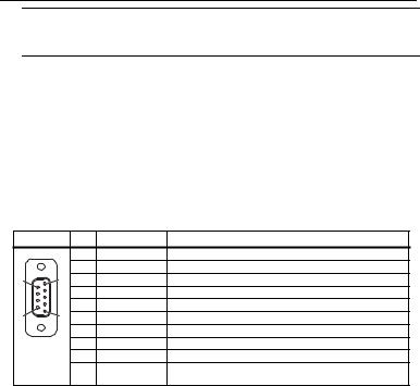
3.3SUB D connector for RS485 interface
Socket
The Control Units CU240S have a 9-pin female sub-D socket for connecting the inverter via an RS485 interface.
|
|
Pin |
Designation |
Description |
|
|
1 |
- |
Unused |
|
|
2 |
- |
Unused |
|
|
3 |
RS485P |
Receiveand transmit signal (+) |
|
|
4 |
- |
Unused |
|
|
5 |
0 V |
Ground reference |
|
|
6 |
- |
Unused |
|
|
7 |
- |
Unused |
|
|
8 |
RS485N |
Receiveand transmit signal (-) |
|
|
9 |
- |
Unused |
|
|
X |
Screen |
Potential equilisation |
|
|
|
(casing) |
|
Control Units CU240S |
13 |
Getting Started, 10/2008, A5E01301803B AC |
 Loading...