


 Loading...
FUJI-Reader
SP
Service Manual
Troubleshooting
|
|
|
|
|
© Siemens AG 2003 |
|
|
|
The reproduction, transmission or |
|
|
|
use of this document or its contents |
|
|
|
is not permitted without express |
|
|
|
written authority. Offenders will be |
|
|
|
liable for damages. All |
rights, |
|
|
including rights created by patent |
|
|
|
grant or registration of a utility |
|
|
|
model _or_ design,_are_ reserved. |
|
|
|
English |
|
|
Print No.: SPB7-420.840.52.01.02 |
Doc. Gen. Date: |
01.03 |
|
Replaces: n.a.

CR-IR347/CR-IR347P
Service Manual
Troubleshooting (MT)

Contents Maintenance Troubleshooting |
0.1 |
CR-IR347 Service Manual – Contents
Troubleshooting (MT)
1. |
Overview of Troubleshooting ...................................................................................... |
MT1-1 |
|
1.1 Flow of Troubleshooting ................................................................................... |
MT1-1 |
|
1.2 How to Understand Error Log........................................................................... |
MT1-3 |
2. |
Error Codes List ........................................................................................................... |
MT2-1 |
3. Format of Detail Information ....................................................................................... |
MT3-1 |
|
|
3.1 Supplementary Explanation of Detail Information.......................................... |
MT3-17 |
|
3.2 Format of Abort Code ........................................................................................ |
MT3-18 |
4. Error Code Analysis Flow (Mechanism)..................................................................... |
MT4-1 |
|
|
03A2, 13A1, 13A2, 23A1, 23A2 .......................................................................... |
MT4-1 |
|
13A4, 13A5 .......................................................................................................... |
MT4-2 |
|
13A6, 13A7 .......................................................................................................... |
MT4-3 |
|
13A8, 23A8 .......................................................................................................... |
MT4-4 |
|
13A9, 23A9 .......................................................................................................... |
MT4-5 |
|
13AA, 23AA......................................................................................................... |
MT4-6 |
|
13AD .................................................................................................................... |
MT4-7 |
|
03B1, 23B1 .......................................................................................................... |
MT4-8 |
|
03B2, 23B2 .......................................................................................................... |
MT4-9 |
|
03B3 .................................................................................................................... |
MT4-10 |
|
03B4, 03B5, 03B6 ............................................................................................... |
MT4-11 |
|
03B7 .................................................................................................................... |
MT4-12 |
|
03BC, 23BA, 23BB, 23BC .................................................................................. |
MT4-13 |
|
03BF, 23BD, 23BE, 23BF ................................................................................... |
MT4-14 |
|
03C1 .................................................................................................................... |
MT4-15 |
|
03C0, 03C2 .......................................................................................................... |
MT4-16 |
|
03C6, 03C8, 03CA, 23C6 .................................................................................... |
MT4-17 |
|
03C7, 03C9, 03CB, 23C7 .................................................................................... |
MT4-18 |
|
03CC .................................................................................................................... |
MT4-19 |
|
03CD .................................................................................................................... |
MT4-20 |
|
03D3 .................................................................................................................... |
MT4-22 |
|
03D5 .................................................................................................................... |
MT4-23 |
|
13E1, 13E2, 13E4, 13E5, 13E9, 23E1, 23E2, 23E4, 23E5, 23E9 ....................... |
MT4-25 |
|
13E3, 23E3 .......................................................................................................... |
MT4-26 |
|
03E8, 23E6, 23E7, 23E8 ..................................................................................... |
MT4-27 |
|
03EE, 03EF, 23EA, 23EB, 23EC, 23ED ............................................................. |
MT4-28 |
|
23F1, 23F2........................................................................................................... |
MT4-29 |
|
13F3, 23F3........................................................................................................... |
MT4-30 |
009-058-03 08.30.2002 FM3476
CR-IR347 Service Manual |
0.1 |
|
|
|
|

Contents Maintenance Troubleshooting |
0.2 |
5. Error Code Analysis Flow (Scanner) .......................................................................... |
MT5-1 |
|
|
0532, 2542, 2570 ................................................................................................. |
MT5-1 |
|
0534, 1533, 2543, 2544, 2571, 2572, 2573, 2574 ............................................... |
MT5-2 |
|
0536, 2535, 2545, 2546 ....................................................................................... |
MT5-3 |
|
0537, 2547, 2575 ................................................................................................. |
MT5-4 |
|
0538, 2530, 2548, 2576 ....................................................................................... |
MT5-5 |
|
0563, 2560, 2561, 2564 ....................................................................................... |
MT5-6 |
6. Error Code Analysis Flow (Electrical) ........................................................................ |
MT6-1 |
|
7. Checkout Flowcharts ................................................................................................... |
MT7-1 |
|
7.1 |
Checking the SK1 .............................................................................................. |
MT7-2 |
7.2 |
Checking the SK2 .............................................................................................. |
MT7-4 |
7.3 |
Checking the SK3 .............................................................................................. |
MT7-6 |
7.4 |
Checking the Ground Connections.................................................................. |
MT7-8 |
7.5 |
Checking the SL1 ............................................................................................... |
MT7-10 |
7.6 |
Checking the SL2 ............................................................................................... |
MT7-12 |
7.7 |
Checking the SL4 ............................................................................................... |
MT7-14 |
7.8 |
Checking the SL5 ............................................................................................... |
MT7-16 |
7.9 |
Checking the SM1 .............................................................................................. |
MT7-18 |
7.10 |
Checking the SN1 .............................................................................................. |
MT7-20 |
7.11 |
Checking the SN2 .............................................................................................. |
MT7-22 |
7.12 |
Checking the SN3 .............................................................................................. |
MT7-24 |
7.13 |
Checking the SN4 .............................................................................................. |
MT7-26 |
7.14 |
Checking the SZ1 (SED08D) ............................................................................. |
MT7-28 |
7.15 |
Checking the SZ2 ............................................................................................... |
MT7-30 |
7.16 |
Checking the SZ3 ............................................................................................... |
MT7-32 |
7.17 |
Checking the SZ4 ............................................................................................... |
MT7-34 |
7.18 |
Checking the ML1 .............................................................................................. |
MT7-36 |
7.19 |
Checking the ML2 .............................................................................................. |
MT7-38 |
7.20 |
Checking the MM1 ............................................................................................. |
MT7-40 |
7.21 |
Checking the MN1 .............................................................................................. |
MT7-42 |
7.22 |
Checking the MN2 .............................................................................................. |
MT7-44 |
7.23 |
Checking the MN3 .............................................................................................. |
MT7-46 |
7.24 |
Checking the MN4 .............................................................................................. |
MT7-48 |
7.25 |
Checking the MZ1 .............................................................................................. |
MT7-50 |
7.26 |
Checking the MZ2 .............................................................................................. |
MT7-52 |
7.27 |
Checking the MZ3 .............................................................................................. |
MT7-54 |
009-058-03 08.30.2002 FM3476
CR-IR347 Service Manual |
0.2 |
|
|
|
|

Contents Maintenance Troubleshooting |
0.3 |
7.28 |
Checking the MZ4 .............................................................................................. |
MT7-56 |
7.29 |
Checking the PL1 ............................................................................................... |
MT7-58 |
7.30 |
Checking the SVL1 ............................................................................................ |
MT7-60 |
7.31 |
Checking the SOLK1 ......................................................................................... |
MT7-62 |
7.32 |
Checking the BCRK1 ......................................................................................... |
MT7-64 |
7.33 |
Checking the BCRN1 ......................................................................................... |
MT7-66 |
7.34 |
Checking the Erasure Lamps (LAMP1-LAMP5) .............................................. |
MT7-68 |
7.35 |
Checking the Polygon (POL) ............................................................................ |
MT7-70 |
7.36 |
Checking the Laser (LDD) ................................................................................. |
MT7-72 |
7.37 |
Checking the Start Point Detector (SYN) ......................................................... |
MT7-74 |
7.38 |
Checking the Photomultiplier (PMT08D) ......................................................... |
MT7-76 |
7.39 |
Checking the Photomultiplier (PMR08C) ......................................................... |
MT7-78 |
7.40 |
Checking the Voltages ...................................................................................... |
MT7-80 |
7.41 |
Checking the Boards ......................................................................................... |
MT7-82 |
7.42 |
Checking the HDD.............................................................................................. |
MT7-84 |
7.43 |
Checking the Monitor ........................................................................................ |
MT7-86 |
8. Circuit Diagram ............................................................................................................ |
MT8-1 |
|
9. Priority Checks to Be Conducted upon Trouble Occurrence ................................... |
MT9-1 |
|
10. Making Analyses of Image Abnormalities ................................................................. |
MT10-1 |
|
10.1 |
Making Analyses in Accordance with Error Codes ........................................ |
MT10-1 |
10.2 |
Making Analyses in the Virtual Image Generation Mode ............................... |
MT10-1 |
|
[1] Vertical streaks ............................................................................................. |
MT10-2 |
|
[2] Horizontal streaks ........................................................................................ |
MT10-3 |
|
[3] Other image abnormalities .......................................................................... |
MT10-4 |
10.3 |
Reference Data - Typical Image Abnormalities ............................................... |
MT10-5 |
009-058-03 08.30.2002 FM3476
CR-IR347 Service Manual |
0.3 |
|
|
|
|

Troubleshooting (MT) Control Sheet |
|
MT - 1 |
|||
|
|
Control Sheet |
|
|
|
|
|
|
|
||
|
|
Issue date |
Revision number |
Reason |
Pages affected |
10/10/2000 |
00 |
New release (FM2732) |
All pages |
||
05/15/2001 |
01 |
Corrections (FM3052) |
MT - 12–47, 53, 54, 63, 64, 64.1, |
||
|
|
|
|
|
64.2, 68, 102, 103, 105, 106 |
08/30/2001 |
02 |
Support for “plus” (support for software |
MT - 29, 32, 33, 36, 43, 46, 52, |
||
|
|
|
|
version A04) (FM3142) |
57, 59-62, 62.1-62.2, 67, 122 |
08/30/2002 |
03 |
Error Code List, Analysis Flow, and other |
All pages |
||
|
|
|
|
information added (FM3476) |
|
009-058-03 08.30.2002 FM3476
CR-IR347 Service Manual |
MT - 1 |
|
|
|
|

MT1 - 1
1. Overview of Troubleshooting
■How to Use the Analysis Flow
(1)Check the error code.
1.1Flow of Troubleshooting
■ Overall Flow
When a trouble occurs, refer to the Troubleshooting Volume along the flow shown below to take remedial action, such as parts replacement, as needed.
 “1.2 How to Understand Error Log”
(2)Refer to the Error Code Table.
If any reference page is found in the “Error Code Analysis Flow” column of the Error Code Table, proceed to its relevant error code analysis flow.
Reference page or reference section number
Trouble occurred
 “9. Priority Checks to Be Conducted upon Trouble Occurrence”
<Error code is displayed>
 “2. Error Code Table”
<Error Code Analysis Flow> |
<Check Flow> |
“4. Error Code Analysis Flow (Mechanism)” |
“7. Check Flow” |
|
|
“5. Error Code Analysis Flow (Scanner)” |
|
<Remedial Action>
 “Checks, Replacement, and Adjustment of Parts Volume”
 “Service Parts List Volume”
Code |
Name |
Significance/Occurrence Condition |
Probable Cause/Remedy |
Analysis Detail |
|
flow Code |
|||||
|
|
|
|
MT4-12 7.1
|
|
|
|
|
|
|
|
|
|
|
|
|
|
|
|
|
|
|
|
|
|
|
|
|
|
|
|
|
|
|
|
|
|
Reference destination, |
|
|
|
|
Summary of the error |
Presumable cause of |
||||
Error code |
|
such as analysis flow, |
||||||
|
|
|
error and remedy |
|||||
|
|
|
check flow, etc. |
|||||
|
Error name |
|
|
|||||
|
|
|
|
|
||||
Section number |
|
|
<Error Code Analysis Flow> |
|
|
|
|
|
|
||
- 1 |
|||||
|
|
|
|
|
MT4- 1 |
|
4. Error Code Analysis Flow (Mechanism) |
■ I/O Locations |
|
|
|
|
|
|
03A2, 13A1, 13A2, 23A1, 23A2 |
Cassette |
|
|
|
|
|
|
■ Error Occurrence Conditions |
|
|
|
|
|
|
|
03A2 Cassette hold release error |
SK3 |
|
|
|
||
|
|
|
|
|
|
||
FR7H2730.EPS |
During routine/initialization/error handling (cassette hold release check), the |
SOLK1 |
|
|
|
||
cassette hold solenoid (SOLK1) is turned ON, but the cassette hold sensor (SK3) |
Cassette set unit |
|
|
|
|||
|
|
|
|
||||
|
does not transition from Close to Open within 0.5 sec (TK14), and retry operation |
FR7H2101.EPS |
|
|
|||
|
■ Preparations |
|
|
|
|
||
|
is performed six times or more (NK11). |
1. Turn OFF and uncover the machine. |
|
||||
|
13A1 Cassette setting error 1 |
2. Check for dirt and other foreign matter (lead character marking chips, etc.) |
|||||
|
During routine/initialization/error handling (cassette hold check), the cassette |
inside the machine. Any foreign matter must be removed. |
|||||
|
hold solenoid (SOLK1) is turned OFF, but the cassette hold sensor (SK3) does |
■ Analysis Flow |
|
|
|
||
|
not transition from Open to Close within 0.5 sec (TK14), and retry operation is |
Note the error log with |
|
|
|
||
|
performed six times or more (NK12). |
|
|
|
|||
|
the M-Utility. |
|
|
|
|
||
|
13A2 Cassette hold release error |
|
“1.2 |
How to View the Error Log” |
|
||
|
During routine/initialization/error handling (cassette hold release check), the |
|
1 |
|
|
|
|
|
|
|
N |
|
|
||
|
cassette hold solenoid (SOLK1) is turned ON, but the cassette hold sensor |
Is the sensor (SK3) normal? |
Replace the sensor (SK3). |
Reference page |
|||
|
|
||||||
|
(SK3) does not transition from Close to Open within 0.5 sec (TK14), and retry |
Y |
“7.3 Checking the SK3” |
|
|||
|
operation is performed six times or more (NK11). |
|
|
||||
|
|
|
N |
|
|
||
|
|
|
Is the solenoid (SOLK1) |
Replace the solenoid (SOLK1). |
|||
|
23A1 Cassette hold failure retry |
|
|||||
|
normal? |
|
|
|
|
||
|
During routine/initialization/error handling (cassette hold check), the cassette |
Y |
“7.31 Checking the SOLK1” |
|
|||
|
hold solenoid (SOLK1) is turned OFF to hold the cassette, but the cassette hold |
|
|||||
|
|
|
N |
1 |
|
||
|
sensor (SK3) does not transition from Open to Close within 0.5 sec (TK14). |
Does the error recur? |
|
||||
|
|
|
|||||
|
23A2 Cassette hold release failure retry |
Y |
|
|
|
|
|
|
During routine/initialization/error handling (cassette hold release check 2), the |
Replace the components in the order indicated below: |
|
||||
|
cassette hold solenoid (SOLK1) is turned ON to release the cassette hold, but the |
|
|||||
|
1. SNS08C board |
|
|
|
|||
|
cassette hold sensor (SK3) does not transition from Close to Open within 0.5 sec |
|
|
|
|||
|
2. DRV08A board |
|
|
|
|||
|
(TK14), and retry operation is performed. |
3. CPU90E board |
|
|
|
||
|
|
|
4. MTH08C board |
|
|
|
|
|
|
|
“15. Removing and Installing the PC Boards” in the “Checks, |
||||
|
|
|
Replacement, and Adjustment of Parts” volume |
|
|||
|
|
|
5.SK3 |
|
|
|
|
|
|
|
“4.7 |
Cassette Hold Sensor (SK3)” in the “Checks, Replacement, |
|||
|
|
|
and Adjustment of Parts” volume |
|
|||
|
|
|
6.SOLK1 |
|
|
|
|
|
|
|
“4.6 |
Cassette Hold Solenoid (SOLK1)” in the “Checks, |
|
||
|
|
|
Replacement, and Adjustment of Parts” volume |
FR7H2201.EP |
|||
|
009-058-00 |
|
|
|
|
|
MT4-1 |
|
CR-IR347 Service Manual |
|
|
|
|
MT - 1 |
|
|
10.20.2000 FM2731 |
|
|
|
|
||
FR7H2731.EPS
009-058-03 |
CR-IR347 Service Manual |
MT1 - 1 |
|
08.30.2002 FM3476 |
|
|
|

MT1 - 2
(3) Troubleshoot according to the analysis flow.
NOTE
When troubleshooting, refer to the Check Flow that describes the checking procedures for troubleshooting individual I/O parts, as well as “Check, Replacement, and Adjustment of Parts” volume.
<Error Code Analysis Flow>
Note the error log with |
|
|
|
|
|
“1.2 How to |
|
|||||
|
|
|
|
|
1 |
|
|
|
||||
the M-Utility. |
|
|
|
|
|
|
N |
|
||||
|
|
|
“1.2 How to View the Error Log" |
|
|
|
N |
A Proceed to the section number page. |
||||
|
|
|
1 |
|
|
Is the sensor (SK1) normal? |
|
|
||||
|
|
|
|
|
|
|
||||||
|
|
|
|
|
|
|
|
|
|
|
||
|
|
|
|
N |
(SK1)Y . |
“7.1 Checking the SK1” |
|
|||||
Is the sensor (SK1) normal? |
|
Replace the sensor |
|
|||||||||
|
|
|
|
|
|
|
|
|
|
|
|
|
|
Y |
“7.1 Checking the SK1” |
|
|
|
|
|
|
||||
|
|
|
|
|
|
|
|
|
|
|
|
|
Is the solenoid (SOLK1)
N
Is the solenoid (SOLK1) Replace the nsolenoidrmal?(SOLK1). normal?
Y 
 “ 7.31 Checking the SOLK1”
Does the error recur? |
N |
1 |
|
||
|
|
|
Y
Replace the PC boards in the following order:
1.SNS08C board
2.DRV08A board
3.CPU90E board
4.MTH08C board
 “15. Removing and Installing the PC Boards”
in the “Checks, Replacement, and Adjustment of Parts” volume
Return to the Error Analysis Flow section number page or indicated page.
|
A |
|
|
|
|
|
|
|
|
|
|
|
|
|
|
|
|
|
|
<Check Flow> |
|
|
|
|
|
|
|
|
|
|
|
|
|
|
|
|
|
|
|
|
|
|
|
|
|
|
|
|
|
|
|
|
|
|
|
MT 7- 2 |
B |
7.1 |
Checking the SK1 |
|
|
|
|
|
|
|
|
|
[2] Checking with the M-Utility |
|
|
||||
|
[1] Analysis Flow |
|
|
|
|
|
|
|
|
|
|
[6] [ENT] [4] [ENT] [3] [ENT] |
|
|
||||
|
|
|
|
|
|
|
|
|
|
|
CHECKS |
|
|
|
||||
|
|
|
|
|
|
|
|
|
|
|
|
|
|
|
|
|
||
|
START |
|
|
|
|
|
|
|
|
|
|
|
|
1. Check that the sensor is “open” when its light path is not blocked. |
||||
|
|
A |
|
|
|
|
|
|
|
|
|
|
|
2. Check that the sensor is “closed” when its light path is blocked. |
||||
|
|
|
|
|
|
|
|
|
|
|
|
|
|
|
|
|
|
|
|
Does the M-Utility |
N |
Are the SNS08C |
|
N |
|
Power OFF. |
|
|
|
|
|
[3] Checking the voltage |
|
|
|
||
|
indicate that the sensor |
board voltages |
|
|
|
|
|
|
|
|
|
|
||||||
|
operation is normal? |
|
normal? |
|
|
|
|
|
|
|
|
|
|
|
|
|
|
|
|
Y |
[2] |
|
Y |
[3] |
|
|
Are the power supply |
N |
Are the fuses for the |
N |
Voltage |
Standard value |
Measurement point |
|
|||
|
|
|
|
unit (JPS-6) voltages |
N |
|
|
|
|
|
|
|||||||
|
|
|
|
|
|
|
|
|
power supply unit |
|
|
|
|
SNS08C |
CN4 |
1-2 |
||
|
|
|
|
|
|
|
|
normal? |
|
|
(JPS-6) normal? |
|
|
+5V |
4.75–5.25 V |
|||
|
|
|
|
Is the SNS08C |
|
N |
|
|
|
|
|
|
|
JPS-6 |
DCOUT2 |
1-2 |
||
|
|
|
|
|
|
Y |
[3] |
|
Y |
[3] |
|
|
|
|||||
|
Return to the error code |
|
board fuse normal? |
|
|
|
|
|
|
|
|
|
||||||
|
|
|
|
|
|
|
|
|
Replace any |
|
|
|
|
TR7H2087.EPS |
||||
|
analysis flow. |
|
|
|
|
|
|
|
|
|
|
|
|
|
|
|
|
|
|
|
|
|
Y |
[7] |
Replace any |
|
|
|
|
|
blown fuse. |
|
SNS08C board |
|
|||
|
|
|
|
|
|
|
|
|
|
|
|
|||||||
|
|
|
|
|
|
blown fuse. |
|
|
|
|
|
|
|
|
|
|
|
|
|
|
|
|
|
|
|
|
|
|
|
Replace the power |
|
|
|
|
|
|
|
|
|
|
|
|
|
|
|
|
|
|
supply unit (JPS-6). |
|
|
|
|
|
|
|
|
|
|
|
|
|
|
|
|
|
|
|
|
|
|
1 |
2 |
|
|
|
|
|
|
Are the cables normal? |
|
N |
|
|
|
|
|
|
|
CN4 |
|
|
|
|
|
|
|
|
|
Replace any faulty cable. |
|
|
|
|
|
|
|
|
|||||
|
|
|
|
|
|
|
|
|
|
|
|
|
|
|
|
|||
B |
|
|
|
Y |
|
|
[5], [6] |
|
|
|
|
|
|
|
|
|
|
|
|
|
|
Is the mechanism normal? |
N |
Repair the mechanism. |
|
|
|
|
|
|
|
|
|||||
|
|
|
|
|
|
|
|
|
|
|
|
|
|
|
|
|||
|
|
|
|
Y |
|
|
[4] |
|
|
|
|
|
|
|
|
|
|
|
|
|
|
|
|
|
|
N |
|
|
|
|
|
|
|
F |
|
|
|
|
|
|
|
Is the sensor normal? |
|
Check the sensor. |
|
|
|
|
|
R |
|
|
|
|||
|
|
|
|
|
|
|
|
|
|
|
|
|
O |
|
|
|
||
|
|
|
|
Y |
|
|
|
|
|
|
|
|
|
|
N |
|
|
|
|
|
|
|
|
“Checks, Replacement, and Adjustment of Parts” |
|
|
|
T |
|
|
|
||||||
|
|
|
|
|
|
volume |
|
|
|
|
|
|
|
|
|
|
|
|
|
|
|
|
Remove and reinstall the |
|
|
|
|
|
|
|
|
Power supply unit (JPS-6) |
|||||
|
|
|
|
CPU90E board and |
|
|
|
|
|
|
|
|
|
|||||
|
|
|
|
connectors. |
|
|
|
|
|
|
|
|
|
|
|
|
|
DC OUT2 |
|
|
|
|
|
|
|
|
|
|
|
|
|
|
|
|
|
|
|
|
|
|
|
|
|
|
|
|
|
|
|
|
|
|
|
|
|
2 |
|
|
|
|
Does the error recur? |
|
N |
A |
|
|
|
|
|
|
|
|
|
1 |
|
|
|
|
|
|
|
|
|
|
|
|
|
|
|
|
||||
|
|
|
|
|
|
|
|
|
|
|
|
|
|
|
|
|
|
|
Y
Replace the PC boards in the following order: |
|
|
|
|
|
|
|
|
|
|
|
|
|
|
|
|
|
|
|
|
|
|
|
1. SNS08C board |
|
|
|
|
|
|
|
|
|
|
|
2. CPU90E board |
|
|
|
|
|
|
|
|
|
|
|
|
|
|
|
|
|
|
|
|
|
|
|
3. MTH08C board |
|
|
|
|
|
|
|
|
|
|
|
“15. Removing and Installing the PC Boards” in the “Checks, |
FR7H2301.EPS |
||||||||||
Replacement, and Adjustment of Parts” volume |
|
|
|
|
|
|
|
|
|
|
FR7H2501.EPS |
|
[4] Checking the mechanism |
||||||||||
• SK1 replacement
“4.3 Cassette Ejection Sensor (SK1)” in the “Checks, Replacement, and Adjustment” volume
009-058-00 |
CR-IR347 Service Manual |
MT7 - 2 |
10.20.2000 FM2731 |
FR7H2732.EPS
009-058-03 |
CR-IR347 Service Manual |
MT1 - 2 |
|
08.30.2002 FM3476 |
|
|
|
MT1 - 3
1.2How to Understand Error Log
When an error code is displayed, check the error log.
■ How to Understand the Error Log List
When multiple errors occurred, the error at the beginning that occurred at the same time (with a margin of about 2-4 minutes) is the most likely cause that is directly responsible for the trouble.
Check the error log to see which is the error at the beginning.
● Error log format
Error code Occurrence date
CODE DATE
03EF 2000.10.18 17:13 001000000000000001-0-0-011-0000101101.------
--.1.0.0.9.0.0.0.0000.0000.0000 23EB 2000.10.18 17:13
111000000000000001-0-0-011-0000101101.------
--.1.0.0.9.0.0.0.0000.0000.0000
FR7H2733.EPS
● How to identify the error code at the beginning
In the error log example shown below, those denoted by “A” and “B” are errors that occurred at the same time (with a margin of about 2 minutes), the error at the beginning for “A” is “23EB”.
Error codes displayed on the screen
CODE DATE
03EF 2000.10.18 17:13 001000000000000001-0-0-011-0000101101.------
--.1.0.0.9.0.0.0.0000.0000.0000 23EB 2000.10.18 17:13
111000000000000001-0-0-011-0000101101.------
A--.1.0.0.9.0.0.0.0000.0000.0000 23EB 2000.10.18 17:13
111000000000000001-0-0-011-0000101101.------  --.1.0.0.9.0.0.0.0000.0000.0000
23EB 2000.10.18 17:13 111000000000000001-0-0-011-0000101101.------  --.1.0.0.9.8.8.8.0000.0000.0000
23E1 2000.10.18 16:55
1110000000000000000000001101000110010.------
--.1.0.0.0.0.0.0.0000.0000.0000
B13A8 2000.10.18 16:55
|
11110000000000000000-0001110000110010.------ |
|
--.1.0.0.6.3.1.0.0000.0000.0000 |
03C2 |
2000.10.18 16:24 |
|
11100000000000000100-0001001000111010.000001 |
|
40.1.5.0.A.0.0.1.0000.0000.0000 |
13B8 |
2000.10.18 16:07 |
|
001000000000000001-0-0-011-1000101111.------ |
|
--.1.5.0.0.0.0.0.0000.0000.0000 |
Error code that occurred last
Error code that occurred third
Error code that occurred second
Error code at the beginning: It should be analyzed first.
0.END 1.NEXT 2.BEFORE (DEFAULT=1) : |
FR7H2734.EPS |
|
|
|
|
|
|
009-058-03 |
CR-IR347 Service Manual |
MT1 - 3 |
|
08.30.2002 FM3476 |
|
|
|
MT1 - 4
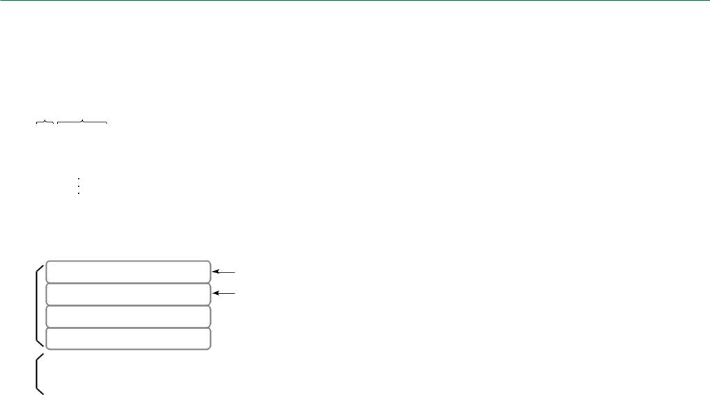
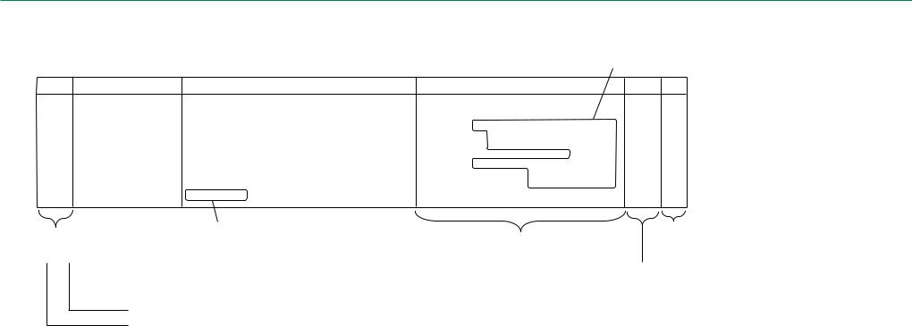
● Error code
An example of error code format is presented below.
Code |
Name |
03BC |
Side-positioning HP |
|
operation error |
||
|
Significance/Occurrence Condition
[During initialization/normal processing]
Although the MN1 turned ON, the SN1 failed to close, allowing the maximum retry count (NN51) to be exceeded.
<I/O name>
•MN1; Side-positioning motor
•SN1; Side-positioning mechanism home position sensor
<Reference>
MD-8.2.8/8.5.2
Probable Cause/Remedy
•Perform the analysis flow for Error 03BC (MT-4).
•Check the MN1 (MT-7.2/MU-4.6/SP-07).
•Check the SN1 (MT-7.10/MU-4.6/MC-8.4).
•Check the side-positioning conveyor mechanism (MD-5.4/MC-8).
•Check the DRV08A board (MT-7.41/MC-15.11).
•Check the SNS08C board (MT-7.41/MC-15.11).
Indicates the reference volume abbreviation and section number.
Analysis
flow Detail
MT4-13 D-5
|
|
|
|
|
|
|
|
Indicates the reference volume |
|
|
|
|
|
|
|
|
abbreviation and section number. |
X |
Y |
Z |
Z |
Hexadecimal notation |
The checks to be performed are listed in random |
|||
order. Judge the target machine condition and |
||||||||
|
|
change the order of checks as needed to begin |
||||||
|
|
|
|
|
||||
|
|
|
|
|
|
|
|
by checking on the most probable error cause. |
|
|
|
|
|
|
|
00-FF: Reference number according to error classification |
|
|
|
|
|
|
|
|
||
See “Section 2.3,
Format of Detail Information”.
Indicates the reference page for “Analysis Flow” in this volume.
0-9, A-F: Error classification
0-3: Error level
X: Error level |
Y: Error classification |
|
• |
FATAL error: 0 |
0: OS (operating system software), CPU, library |
|
Error where the normal processing cannot be resumed. |
1: Overall control, information gathering function, |
|
It is necessary to troubleshoot and take remedial action immediately. |
output destination control function |
• |
WARNING: 1, 2, 3 |
2: Panel control |
|
Errors where the processing may be resumed by performing retry |
3: Conveyor-related control |
|
operation, etc. |
4: Image processing related (reading) |
|
This category includes an error that is merely logged as history information |
5: Scanner control |
|
and an error where the processing is resumed but its error code is displayed |
6: Undefined |
|
on screen. |
7: IDT interface control |
ZZ: Reference number
Managed according to the error classification
8:Printer interface control
9:Undefined
A:ID information setup function
B:Network output image processing
C:FINP control
D:DICOM control
E:Undefined
F:Other (software install, version update, etc.)
FR1H1316.EPS
009-058-03 |
CR-IR347 Service Manual |
MT1 - 4 |
|
08.30.2002 FM3476 |
|
|
|
|
|
|
|
MT2-1 |
||
2. Error Codes List |
|
|
|
|
||
|
|
|
|
|
|
|
Code |
Name |
Significance/Occurrence Condition |
Probable Cause/Remedy |
Analysis |
Detail |
|
flow |
||||||
|
|
|
|
|
||
0100 |
Board insertion position error |
[During initialization] |
• Check the board insertion location (MC-15). |
|
|
|
• Check for improper board setup (MC-15). |
- |
A-8 |
||||
The board insertion slot position was found to be abnormal when it was checked. |
||||||
|
|
|
• Check the board (MT-7.41). |
|
|
|
|
|
|
|
|
|
|
|
|
|
• Check for an improper software update (MU-A1.2). |
|
|
|
0101 |
ID information control system |
[During initialization/normal processing] |
• Check the CPU90E board (MT-7.41/MC-15.3). |
- |
|
|
• Check the MTH08C/D board (MT-7.41/MC-15.1/MC-15.2). |
F |
|||||
initialization error |
The ID information control system (IMM) was found to be abnormal. |
|||||
• Check the HDD (MT-7.42/MC-11). |
|
|
||||
|
|
|
• Format the HDD and reinstall the software (MU-A1). |
|
|
|
|
|
|
|
|
|
|
0102 |
Common data control system |
|
• Check the CPU90E board (MT-7.41/MC-15.3). |
|
|
|
[During initialization] |
• Check the MTH08C/D board (MT-7.41/MC-15.1/MC-15.2). |
- |
F |
|||
initialization error |
An error was detected in the common data control system (CDM). |
• Check the HDD (MT-7.42/MC-11). |
||||
|
|
• Format the HDD and reinstall the software (MU-A1). |
|
|
||
|
|
|
|
|
||
|
|
|
|
|
|
|
0110 |
Image control system |
|
• Check the CPU90E board (MT-7.41/MC-15.3). |
|
|
|
[During initialization/normal processing] |
• Check the MTH08C/D board (MT-7.41/MC-15.1/MC-15.2). |
- |
F |
|||
initialization error |
An error was detected in the image control system (IDM). |
• Check the HDD (MT-7.42/MC-11). |
||||
|
|
• Format the HDD and reinstall the software (MU-A1). |
|
|
||
|
|
|
|
|
||
|
|
|
|
|
|
|
009-058-03 |
CR-IR347 Service Manual |
[ 2. ] |
MT2-1 |
|
08.30.2002 FM3476 |
||||
|
|
|
|
|
|
|
|
MT2-2 |
|
|
|
|
|
|
|
|
Code |
Name |
Significance/Occurrence Condition |
Probable Cause/Remedy |
Analysis |
Detail |
|
flow |
|
|||||
|
|
|
|
|
|
|
0111 |
HD image display area |
|
• Check the CPU90E board (MT-7.41/MC-15.3). |
|
|
|
[During initialization/normal processing] |
• Check the MTH08C/D board (MT-7.41/MC-15.1/MC-15.2). |
- |
|
F |
||
initialization error |
An error was detected in the HD image display area. |
• Check the HDD (MT-7.42/MC-11). |
|
|||
|
|
• Format the HDD and reinstall the software (MU-A1). |
|
|
|
|
|
|
|
|
|
|
|
|
|
|
|
|
|
|
|
|
|
• Check the CPU90E board (MT-7.41/MC-15.3). |
|
|
|
0112 |
|
[During initialization/normal processing] |
• Check the MTH08C/D board (MT-7.41/MC-15.1/MC-15.2). |
|
|
|
No effective option |
• Check the MMA90A and MMB90A/DIM08A board |
- |
|
|
||
An error was detected when shared memory allocation was attempted for option |
|
F |
||||
(MT-7.41/MC-15/IN-5.5). |
|
|||||
|
|
configuration. |
• Check the HDD (MT-7.42/MC-11). |
|
|
|
|
|
|
|
|
|
|
|
|
|
• Format the HDD and reinstall the software (MU-A1). |
|
|
|
|
|
|
|
|
|
|
0113 |
Not enough common memory |
[During initialization] |
• Check the MTH08C/D board (MT-7.41/MC-15.1/MC-15.2). |
|
|
|
• Check the MMA90A and MMB90A/DIM08A board |
- |
|
E-5 |
|||
It was detected that the capacity of the common memory is insufficient. |
|
|||||
|
|
|
(MT-7.41/MC-15/IN-5.5). |
|
|
|
|
|
|
|
|
|
|
0120 |
|
[During initialization] |
• Check the CPU90E board (MT-7.41/MC-15.3). |
|
|
|
File open error |
• Check the MTH08C/D board (MT-7.41/MC-15.1/MC-15.2). |
- |
|
|
||
An error was detected when an attempt was made to open a configuration file |
|
A-1 |
||||
• Check the HDD (MT-7.42/MC-11). |
|
|||||
|
|
(NETMASKS). |
• Format the HDD and reinstall the software (MU-A1). |
|
|
|
|
|
|
|
|
|
|
|
|
|
|
|
|
|
009-058-03 |
CR-IR347 Service Manual |
[ 2. ] |
MT2-2 |
|
08.30.2002 FM3476 |
||||
|
|
|
|
|
|
|
|
MT2-3 |
|
|
|
|
|
|
|
|
Code |
Name |
Significance/Occurrence Condition |
Probable Cause/Remedy |
Analysis |
Detail |
|
flow |
|
|||||
|
|
|
|
|
|
|
0121 |
|
[During initialization] |
• Check the CPU90E board (MT-7.41/MC-15.3). |
|
|
|
File read error |
• Check the MTH08C/D board (MT-7.41/MC-15.1/MC-15.2). |
- |
|
|
||
An error was detected when an attempt was made to read a configuration file |
|
A-1 |
||||
• Check the HDD (MT-7.42/MC-11). |
|
|||||
|
|
(NETMASKS). |
• Format the HDD and reinstall the software (MU-A1). |
|
|
|
|
|
|
|
|
|
|
|
|
|
|
|
|
|
0122 |
|
[During initialization] |
• Check the CPU90E board (MT-7.41/MC-15.3). |
|
|
|
File close error |
• Check the MTH08C/D board (MT-7.41/MC-15.1/MC-15.2). |
- |
|
|
||
An error was detected when an attempt was made to close a configuration file |
|
A-1 |
||||
• Check the HDD (MT-7.42/MC-11). |
|
|||||
|
|
(NETMASKS). |
• Format the HDD and reinstall the software (MU-A1). |
|
|
|
|
|
|
|
|
|
|
|
|
|
|
|
|
|
0123 |
|
|
• Check the configuration settings (MU-4.2). |
|
|
|
File format error |
[During initialization] |
• Check the CPU90E board (MT-7.41/MC-15.3). |
- |
|
A-1 |
|
An error was found in the format of a configuration file (NETMASKS). |
• Check the MTH08C/D board (MT-7.41/MC-15.1/MC-15.2). |
|
||||
|
|
|
• Check the HDD (MT-7.42/MC-11). |
|
|
|
|
|
|
|
|
|
|
0130 |
|
[During initialization] |
• Check the CPU90E board (MT-7.41/MC-15.3). |
|
|
|
File open error |
• Check the MTH08C/D board (MT-7.41/MC-15.1/MC-15.2). |
- |
|
|
||
An error was detected when an attempt was made to open a configuration file |
|
A-1 |
||||
• Check the HDD (MT-7.42/MC-11). |
|
|||||
|
|
(HOSTS ADDRESS). |
• Format the HDD and reinstall the software (MU-A1). |
|
|
|
|
|
|
|
|
|
|
|
|
|
|
|
|
|
009-058-03 |
CR-IR347 Service Manual |
[ 2. ] |
MT2-3 |
|
08.30.2002 FM3476 |
||||
|
|
|
|
|
|
|
|
MT2-4 |
|
|
|
|
|
|
|
|
Code |
Name |
Significance/Occurrence Condition |
Probable Cause/Remedy |
Analysis |
Detail |
|
flow |
|
|||||
|
|
|
|
|
|
|
0131 |
|
[During initialization] |
• Check the CPU90E board (MT-7.41/MC-15.3). |
|
|
|
File read error |
• Check the MTH08C/D board (MT-7.41/MC-15.1/MC-15.2). |
- |
|
|
||
An error was detected when an attempt was made to read a configuration file |
|
A-1 |
||||
• Check the HDD (MT-7.42/MC-11). |
|
|||||
|
|
(HOSTS ADDRESS). |
• Format the HDD and reinstall the software (MU-A1). |
|
|
|
|
|
|
|
|
|
|
|
|
|
|
|
|
|
0132 |
|
[During initialization] |
• Check the CPU90E board (MT-7.41/MC-15.3). |
|
|
|
File close error |
• Check the MTH08C/D board (MT-7.41/MC-15.1/MC-15.2). |
- |
|
|
||
An error was detected when an attempt was made to close a configuration file |
|
A-1 |
||||
• Check the HDD (MT-7.42/MC-11). |
|
|||||
|
|
(HOSTS ADDRESS). |
• Format the HDD and reinstall the software (MU-A1). |
|
|
|
|
|
|
|
|
|
|
|
|
|
|
|
|
|
0133 |
|
|
• Check the configuration settings (MU-4.2). |
|
|
|
File format error |
[During initialization] |
• Check the CPU90E board (MT-7.41/MC-15.3). |
- |
|
A-1 |
|
An error was found in the format of a configuration file (HOSTS ADDRESS). |
• Check the MTH08C/D board (MT-7.41/MC-15.1/MC-15.2). |
|
||||
|
|
|
• Check the HDD (MT-7.42/MC-11). |
|
|
|
|
|
|
|
|
|
|
0134 |
|
[During initialization] |
• Check the configuration settings (MU-4.2). |
|
|
|
File setting value error |
• Check the CPU90E board (MT-7.41/MC-15.3). |
- |
|
|
||
An error was found in the settings contained in a configuration file (HOSTS |
|
A-1 |
||||
• Check the MTH08C/D board (MT-7.41/MC-15.1/MC-15.2). |
|
|||||
|
|
ADDRESS). |
• Check the HDD (MT-7.42/MC-11). |
|
|
|
|
|
|
|
|
|
|
|
|
|
|
|
|
|
0140 |
Boot line-related error |
[During initialization] |
• Check the CPU90E board (MT-7.41/MC-15.3). |
- |
|
F |
An error was detected in the backup memory data. |
|
|||||
|
|
|
|
|
|
|
009-058-03 |
CR-IR347 Service Manual |
[ 2. ] |
MT2-4 |
|
08.30.2002 FM3476 |
||||
|
|
|
|
|
|
|
|
MT2-5 |
|
|
|
|
|
|
|
|
Code |
Name |
Significance/Occurrence Condition |
Probable Cause/Remedy |
Analysis |
Detail |
|
flow |
|
|||||
|
|
|
|
|
|
|
0141 |
Routing information-related |
[During initialization] |
• Check the configuration settings (MU-4.2). |
|
|
|
• Check the CPU90E board (MT-7.41/MC-15.3). |
- |
|
|
|||
An error was found in the settings contained in a configuration file |
|
F |
||||
error |
• Check the MTH08C/D board (MT-7.41/MC-15.1/MC-15.2). |
|
||||
|
(ROUTING/HOSTS ADDRESS). |
• Check the HDD (MT-7.42/MC-11). |
|
|
|
|
|
|
|
|
|
|
|
|
|
|
|
|
|
|
|
|
|
• Check the CPU90E board (MT-7.41/MC-15.3). |
|
|
|
01A0 |
ID information read error |
[During initialization/normal processing] |
• Check the MTH08C/D board (MT-7.41/MC-15.1/MC-15.2). |
- |
|
|
• Check the MMA90A and MMB90A/DIM08A board |
|
D |
||||
An error was detected when an attempt was made to read ID information. |
|
|||||
|
|
|
(MT-7.41/MC-15/IN-5.5). |
|
|
|
|
|
|
• Check the HDD (MT-7.42/MC-11). |
|
|
|
|
|
|
|
|
|
|
|
|
|
• Check the CPU90E board (MT-7.41/MC-15.3). |
|
|
|
01A1 |
ID information update error |
[During initialization/normal processing] |
• Check the MTH08C/D board (MT-7.41/MC-15.1/MC-15.2). |
- |
|
|
• Check the MMA90A and MMB90A/DIM08A board |
|
D |
||||
An error was detected when an attempt was made to update ID information. |
|
|||||
|
|
|
(MT-7.41/MC-15/IN-5.5). |
|
|
|
|
|
|
• Check the HDD (MT-7.42/MC-11). |
|
|
|
|
|
|
|
|
|
|
01A2 |
|
|
• Check the CPU90E board (MT-7.41/MC-15.3). |
|
|
|
Image data close error |
[During initialization/normal processing] |
• Check the MTH08C/D board (MT-7.41/MC-15.1/MC-15.2). |
- |
|
D |
|
An error was detected when an attempt was made to close an image data file. |
• Check the HDD (MT-7.42/MC-11). |
|
||||
|
|
|
• Format the HDD and reinstall the software (MU-A1). |
|
|
|
|
|
|
|
|
|
|
009-058-03 |
CR-IR347 Service Manual |
[ 2. ] |
MT2-5 |
|
08.30.2002 FM3476 |
||||
|
|
|
|
|
|
|
|
MT2-6 |
|
|
|
|
|
|
|
|
Code |
Name |
Significance/Occurrence Condition |
Probable Cause/Remedy |
Analysis |
Detail |
|
flow |
|
|||||
|
|
|
|
|
|
|
01A3 |
|
|
• Check the configuration settings (MU-4.2). |
|
|
|
EQUIP file format error |
[During initialization] |
• Check the CPU90E board (MT-7.41/MC-15.3). |
- |
|
D |
|
An error was found in the format contained in a configuration file (EQUIPMENT). |
• Check the MTH08C/D board (MT-7.41/MC-15.1/MC-15.2). |
|
||||
|
|
|
• Check the HDD (MT-7.42/MC-11). |
|
|
|
|
|
|
|
|
|
|
|
|
|
• Check the CPU90E board (MT-7.41/MC-15.3). |
|
|
|
0200 |
Image data close error |
[During U-Utility mode] |
• Check the MTH08C/D board (MT-7.41/MC-15.1/MC-15.2). |
- |
|
|
An error was detected when an attempt was made to delete an image queued for |
• Check the MMA90A and MMB90A/DIM08A board |
|
- |
|||
|
|
processing. |
(MT-7.41/MC-15/IN-5.5). |
|
|
|
|
|
|
• Check the HDD (MT-7.42/MC-11). |
|
|
|
|
|
|
|
|
|
|
0301 |
|
[During initialization] |
• Check the CPU90E board (MT-7.41/MC-15.3). |
|
|
|
File open error |
• Check the MTH08C/D board (MT-7.41/MC-15.1/MC-15.2). |
- |
|
|
||
An error was detected when an attempt was made to open a subsystem (IPH) file |
|
D-1 |
||||
• Check the HDD (MT-7.42/MC-11). |
|
|||||
|
|
on the HDD. |
• Format the HDD and reinstall the software (MU-A1). |
|
|
|
|
|
|
|
|
|
|
|
|
|
|
|
|
|
0302 |
|
|
• Check the CPU90E board (MT-7.41/MC-15.3). |
|
|
|
File format error |
[During initialization] |
• Check the MTH08C/D board (MT-7.41/MC-15.1/MC-15.2). |
- |
|
D-1 |
|
An error was found in the data format of a subsystem (IPH) file on the HDD. |
• Check the HDD (MT-7.42/MC-11). |
|
||||
|
|
|
• Format the HDD and reinstall the software (MU-A1). |
|
|
|
|
|
|
|
|
|
|
009-058-03 |
CR-IR347 Service Manual |
[ 2. ] |
MT2-6 |
|
08.30.2002 FM3476 |
||||
|
|
|
|
|
|
|
|
MT2-7 |
|
|
|
|
|
|
|
|
Code |
Name |
Significance/Occurrence Condition |
Probable Cause/Remedy |
Analysis |
Detail |
|
flow |
|
|||||
|
|
|
|
|
|
|
0303 |
|
[During initialization] |
• Check the CPU90E board (MT-7.41/MC-15.3). |
|
|
|
File setting value error |
• Check the MTH08C/D board (MT-7.41/MC-15.1/MC-15.2). |
- |
|
|
||
An error was found in the setting data contained in a subsystem (IPH) file on the |
|
D-1 |
||||
• Check the HDD (MT-7.42/MC-11). |
|
|||||
|
|
HDD. |
• Format the HDD and reinstall the software (MU-A1). |
|
|
|
|
|
|
|
|
|
|
|
|
|
|
|
|
|
0304 |
|
[During initialization] |
• Check the CPU90E board (MT-7.41/MC-15.3). |
|
|
|
File read error |
• Check the MTH08C/D board (MT-7.41/MC-15.1/MC-15.2). |
- |
|
|
||
An error was detected when an attempt was made to read a subsystem (IPH) file |
|
D-1 |
||||
• Check the HDD (MT-7.42/MC-11). |
|
|||||
|
|
on the HDD. |
• Format the HDD and reinstall the software (MU-A1). |
|
|
|
|
|
|
|
|
|
|
|
|
|
|
|
|
|
0311 |
FPMC device error |
[During initialization] |
|
|
|
|
An error was detected when an attempt was made to initialize the FPMC device |
• Check the CPU90E board (MT-7.41/MC-15.3). |
- |
|
D-3 |
||
|
|
for the CPU memory (CPU90E board). |
|
|
|
|
|
|
|
|
|
|
|
0312 |
Motor stop time-out |
[During initialization/normal processing] |
• Check the CPU90E board (MT-7.41/MC-15.3). |
|
|
|
Although a pulse motor drive request or stop request was issued, a timeout |
• Check the DRV08A board (MT-7.41/MC-15.11). |
- |
|
D-3 |
||
|
|
occurred because the target pulse motor could not be driven or stopped. |
• Check the SNS08C board (MT-7.41/MC-15.11). |
|
|
|
|
|
|
|
|
|
|
0322 |
SNS device error |
[During initialization] |
• Check the CPU90E board (MT-7.41/MC-15.3). |
- |
|
D-3 |
An error was detected when an attempt was made to initialize the SNS device. |
|
|||||
|
|
|
|
|
|
|
009-058-03 |
CR-IR347 Service Manual |
[ 2. ] |
MT2-7 |
|
08.30.2002 FM3476 |
||||
|
|
|
|
|
|
|
|
MT2-8 |
|
|
|
|
|
|
|
|
Code |
Name |
Significance/Occurrence Condition |
Probable Cause/Remedy |
Analysis |
Detail |
|
flow |
|
|||||
|
|
|
|
|
|
|
|
|
[During initialization/normal processing/M-Utility mode/abnormality processing] |
|
|
|
|
|
|
Although the SOLK1 turned ON, the SK3 failed to open, allowing the maximum |
• Perform the analysis flow for Error 03A2 (MT-4). |
|
|
|
|
|
retry count (NK11) to be exceeded. |
|
|
|
|
|
|
• Check the SOLK1 (MT-7.31/MU-4.6/MC-4.6). |
|
|
|
|
|
|
|
|
|
|
|
03A2 |
Cassette hold release error |
<I/O name> |
• Check the SK3 (MT-7.3/MU-4.6/MC-4.7). |
MT4-1 |
|
|
• Check the cassette set unit mechanism (MD-5.1/MC-4). |
|
D-5 |
||||
• SOLK1; Cassette hold solenoid |
|
|||||
|
|
• SK3; Cassette hold sensor |
• Check the cassette. |
|
|
|
|
|
• Check the DRV08A board (MT-7.41/MC-15.11). |
|
|
|
|
|
|
|
|
|
|
|
|
|
<Reference> |
• Check the SNS08C board (MT-7.41/MC-15.11). |
|
|
|
|
|
|
|
|
|
|
|
|
MD-8.6.2 |
|
|
|
|
|
|
|
|
|
|
|
|
|
[During initialization] |
• Check the IP and cassette. |
|
|
|
|
|
• Check the MM1 (MT-7.20/MU-4.6/MC-6.14). |
|
|
|
|
|
|
When the IP size was checked, the CLOSE time combination of the SM1 did not |
|
|
|
|
|
|
• Check the MN3 (MT-7.23/MU-4.6/SP-07). |
|
|
|
|
|
|
agree with the IP size data stored in the machine. |
|
|
|
|
|
Nonstandard initialization IP |
• Check the SM1 (MT-7.9/MU-4.6/SP-05). |
|
|
|
|
03A8 |
|
|
|
|
||
<I/O name> |
• Check the cassette set unit mechanism (MD-5.1/MC-4). |
- |
|
D-5 |
||
size |
• Check the IP removal unit mechanism (MD-5.2/MC-5). |
|
||||
|
• SM1; Before-BCR IP sensor |
• Check the side-positioning conveyor mechanism |
|
|
|
|
|
|
|
|
|
|
|
|
|
<Reference> |
(MD-5.4/MC-8). |
|
|
|
|
|
• Check the DRV08A board (MT-7.41/MC-15.11). |
|
|
|
|
|
|
MD-8.2.4 (IP identification condition table) |
|
|
|
|
|
|
• Check the SNS08C board (MT-7.41/MC-15.11). |
|
|
|
|
|
|
|
|
|
|
|
|
|
|
|
|
|
|
|
|
[During initialization] |
|
|
|
|
|
|
When the machine was searched for IPs, the remaining IP process could not be |
• Check the SK1 (MT-7.1/MU-4.6/MC-4.3). |
|
|
|
|
IP feed/load conveyor |
performed for one of the following reasons: |
|
|
|
|
03B0 |
|
• Check the SK2 (MT-7.2/MU-4.6/MC-4.9). |
|
|
|
|
remaining IP discharge |
• Cassette detection was not achievable. |
• Clear the backup memory and then perform a reset (IN-17). |
- |
|
D-5 |
|
|
impossible |
• The CMOS information was abnormal. |
• Check the cassette. |
|
|
|
|
<Reference> |
• Check the cassette set unit mechanism (MD-5.1/MC-4). |
|
|
|
|
|
|
|
|
|
|
|
|
|
MD-8.5.8 |
|
|
|
|
|
|
|
|
|
|
|
009-058-03 |
CR-IR347 Service Manual |
[ 2. ] |
MT2-8 |
|
08.30.2002 FM3476 |
||||
|
|
|
|
|
|
|
|
MT2-9 |
|
|
|
|
|
|
|
|
Code |
Name |
Significance/Occurrence Condition |
Probable Cause/Remedy |
Analysis |
Detail |
|
flow |
|
|||||
|
|
|
|
|
|
|
|
|
|
• Perform the analysis flow for Error 03B1 (MT-4). |
|
|
|
|
|
[During initialization/normal processing] |
• Check the MN3 (MT-7.23/MU-4.6/SP-07). |
|
|
|
|
|
Although the MN3/MM1/ML2 was turned ON, the SM1 did not close and a timeout |
• Check the MM1 (MT-7.20/MU-4.6/MC-6.14). |
|
|
|
|
|
occurred. |
• Check the ML2 (MT-7.19/MU-4.6/MC-5.22). |
|
|
|
03B1 |
|
|
• Check the SM1 (MT-7.9/MU-4.6/SP-05). |
|
|
|
IP feed conveyance error |
<I/O name> |
• Check the IP removal unit mechanism (MD-5.2/MC-5). |
MT4-8 |
|
D-5 |
|
• MN3/MM1/ML2; IP transport motor |
• Check the side-positioning conveyor mechanism |
|
||||
|
|
• SM1; Before-BCR IP sensor |
(MD-5.4/MC-8). |
|
|
|
|
|
|
• Check the fuse (F11) for the power supply (JPS-6) |
|
|
|
|
|
<Reference> |
(MD-1.6/MT-7.40/MC-13.2). |
|
|
|
|
|
MD-8.2.3 |
• Check the DRV08A board (MT-7.41/MC-15.11). |
|
|
|
|
|
|
• Check the SNS08C board (MT-7.41/MC-15.11). |
|
|
|
|
|
|
|
|
|
|
|
|
[During initialization/normal processing] |
• Perform the analysis flow for Error 03B2 (MT-4). |
|
|
|
|
|
Although the ML2/MM1/MN3 turned ON, a timeout occurred because the SK2 |
|
|
|
|
|
|
failed to close. |
• Check the ML2 (MT-7.19/MU-4.6/MC-5.22). |
|
|
|
03B2 |
|
|
• Check the MM1 (MT-7.20/MU-4.6/MC-6.14). |
|
|
|
IP load conveyance error |
<I/O name> |
• Check the MN3 (MT-7.23/MU-4.6/SP-07). |
MT4-9 |
|
D-5 |
|
• ML2/MM1/MN3; IP transport motor |
• Check the SK2 (MT-7.2/MU-4.6/MC-4.9). |
|
||||
|
|
• SK2; Cassette IN sensor |
• Check the IP removal unit mechanism (MD-5.2/MC-5). |
|
|
|
|
|
|
• Check the DRV08A board (MT-7.41/MC-15.11). |
|
|
|
|
|
<Reference> |
• Check the SNS08C board (MT-7.41/MC-15.11). |
|
|
|
|
|
MD-8.2.16/8.2.17/8.4.1 |
|
|
|
|
|
|
|
|
|
|
|
009-058-03 |
CR-IR347 Service Manual |
[ 2. ] |
MT2-9 |
|
08.30.2002 FM3476 |
||||
|
|
|
|
|
|
|
MT2-10 |
||
|
|
|
|
|
|
|
Code |
Name |
Significance/Occurrence Condition |
Probable Cause/Remedy |
Analysis |
Detail |
|
flow |
||||||
|
|
|
|
|
||
|
|
[During initialization/normal processing] |
|
|
|
|
|
|
Although the MN3 turned ON, the SN3 did not close after the SM1 closing. |
• Perform the analysis flow for Error 03B3 (MT-4). |
|
|
|
|
|
Therefore, a retry operation was performed. |
|
|
||
|
|
|
• Check the MN3 (MT-7.23/MU-4.6/SP-07). |
|
|
|
03B3 |
Side-positioning conveyor |
<I/O name> |
• Check the SN3 (MT-7.12/MU-4.6/MC-8.8). |
MT4-10 |
|
|
• MN3; IP transport motor |
• Check the side-positioning conveyor mechanism |
D-5 |
||||
entrance conveyance error |
||||||
• SM1; Before-BCR IP sensor |
(MD-5.4/MC-8). |
|
|
|||
|
|
• SN3; Side-positioning IP sensor |
• Check the DRV08A board (MT-7.41/MC-15.11). |
|
|
|
|
|
<Reference> |
• Check the SNS08C board (MT-7.41/MC-15.11). |
|
|
|
|
|
|
|
|
||
|
|
MD-8.2.6 |
|
|
|
|
|
|
|
|
|
|
|
|
|
[During normal processing/abnormality processing] |
• Perform the analysis flow for Error 03B4 (MT-4). |
|
|
|
|
|
Although the MN3/MM1/ML2 turned ON, the SL2 did not open. |
|
|
||
|
|
• Check the MN3 (MT-7.23/MU-4.6/SP-07). |
|
|
||
|
|
|
|
|
||
03B4 |
Restored IP load low-speed |
<I/O name> |
• Check the MM1 (MT-7.20/MU-4.6/MC-6.14). |
|
|
|
• Check the ML2 (MT-7.19/MU-4.6/MC-5.22). |
MT4-11 |
D-5 |
||||
• MN3/MM1/ML2; IP transport motor |
||||||
conveyance error |
• Check the SL2 (MT-7.6/MU-4.6/SP-04). |
|||||
|
• SL2; Cassette inlet IP sensor |
• Check the IP removal unit mechanism (MD-5.2/MC-5). |
|
|
||
|
|
|
|
|
||
|
|
<Reference> |
• Check the DRV08A board (MT-7.41/MC-15.11). |
|
|
|
|
|
• Check the SNS08C board (MT-7.41/MC-15.11). |
|
|
||
|
|
MD-8.3.1 |
|
|
||
|
|
|
|
|
||
|
|
|
|
|
|
|
|
|
[During normal processing/abnormality processing] |
• Perform the analysis flow for Error 03B5 (MT-4). |
|
|
|
|
|
Although the MN3/MM1/ML2 turned ON, the SL2 did not close. |
|
|
||
|
|
• Check the MN3 (MT-7.23/MU-4.6/SP-07). |
|
|
||
|
|
|
|
|
||
03B5 |
Restored IP load high-speed |
<I/O name> |
• Check the MM1 (MT-7.20/MU-4.6/MC-6.14). |
|
|
|
• Check the ML2 (MT-7.19/MU-4.6/MC-5.22). |
MT4-11 |
D-5 |
||||
conveyance error |
• MN3/MM1/ML2; IP transport motor |
• Check the SL2 (MT-7.6/MU-4.6/SP-04). |
||||
|
• SL2; Cassette inlet IP sensor |
• Check the IP removal unit mechanism (MD-5.2/MC-5). |
|
|
||
|
|
|
|
|
||
|
|
<Reference> |
• Check the DRV08A board (MT-7.41/MC-15.11). |
|
|
|
|
|
• Check the SNS08C board (MT-7.41/MC-15.11). |
|
|
||
|
|
MD-8.3.1 |
|
|
||
|
|
|
|
|
||
|
|
|
|
|
|
|
009-058-03 |
CR-IR347 Service Manual |
[ 2. ] |
MT2-10 |
|
08.30.2002 FM3476 |
||||
|
|
|
|
|
|
|
MT2-11 |
||
|
|
|
|
|
|
|
Code |
Name |
Significance/Occurrence Condition |
Probable Cause/Remedy |
Analysis |
Detail |
|
flow |
||||||
|
|
|
|
|
||
03B6 |
IP feed/load conveyor |
remaining IP discharge error |
|
|
|
[During initialization] |
• Perform the analysis flow for Error 03B6 (MT-4). |
|
|
• Although the ML2/MM1/MN3 turned ON, the SL2 did not open. |
• Check the ML2 (MT-7.19/MU-4.6/MC-5.22). |
|
|
• Although the ML2/MM1/MN3 turned ON, the SM1 did not open. |
• Check the MM1 (MT-7.20/MU-4.6/MC-6.14). |
|
|
• Although the ML2 turned ON, the SL2 did not open. |
• Check the MN3 (MT-7.23/MU-4.6/SP-07). |
|
|
• An error was found in the CMOS information. |
• Check the SL2 (MT-7.6/MU-4.6/SP-04). |
|
|
|
• Check the SM1 (MT-7.9/MU-4.6/SP-05). |
MT4-11 |
D-5 |
<I/O name> |
• Check the IP removal unit mechanism (MD-5.2/MC-5). |
||
• ML2/MM1/MN3; IP transport motor |
• Check the side-positioning conveyor mechanism |
|
|
• SL2; Cassette inlet IP sensor |
(MD-5.4/MC-8). |
|
|
• SM1; Before-BCR IP sensor |
• Clear the backup memory and then perform a reset (IN-17). |
|
|
|
• Check the MTH08C/D board (MT-7.41/MC-15.1/MC-15.2). |
|
|
<Reference> |
• Check the DRV08A board (MT-7.41/MC-15.11). |
|
|
MD-8.5.6/8.5.8/8.5.10 |
• Check the SNS08C board (MT-7.41/MC-15.11). |
|
|
|
|
|
|
009-058-03 |
CR-IR347 Service Manual |
[ 2. ] |
MT2-11 |
|
08.30.2002 FM3476 |
||||
|
|
|
|
|
|
|
MT2-12 |
||
|
|
|
|
|
|
|
Code |
Name |
Significance/Occurrence Condition |
Probable Cause/Remedy |
Analysis |
Detail |
|
flow |
||||||
|
|
|
|
|
||
|
|
[During initialization] |
|
|
|
|
|
|
• Although the MN3 and MZ1 turned ON to reverse for the purpose of moving |
|
|
|
|
|
|
the remaining IP in the before-reading conveyor, the SM1 did not close. Or |
|
|
|
|
|
|
when the MN3 turned ON for feed conveyance after the SM1 close, the SN3 |
|
|
|
|
|
|
did not close. |
• Perform the analysis flow for Error 03B7 (MT-4). |
|
|
|
|
|
• Although the MN3 turned ON for feed conveyance to search for a remaining |
|
|
||
|
|
• Check the MN3 (MT-7.23/MU-4.6/SP-07). |
|
|
||
|
|
IP in the before-reading conveyor, the SN3 did not close. |
|
|
||
|
|
• Check the MZ1 (MT-7.25/MC-10.6). |
|
|
||
|
|
|
|
|
||
|
|
[During initialization/normal processing] |
• Check the SN3 (MT-7.12/MU-4.6/MC-8.8). |
|
|
|
|
|
• Check the SM1 (MT-7.9/MU-4.6/SP-05). |
|
|
||
|
Side-positioning conveyor |
Although the ML2/MM1/MN3 turned ON for feed conveyance to move the |
|
|
||
03B7 |
• Check the SZ1 (MT-7.14/MC-10.11). |
|
|
|||
remaining IP in the before-reading conveyor, the SM1 did not open. |
MT4-12 |
D-5 |
||||
• Check the side-positioning conveyor mechanism |
||||||
remaining IP discharge error |
Or when the MN3 turned ON for feed conveyance after the SM1 close, the SN3 |
|||||
(MD-5.4/MC-8). |
|
|
||||
|
|
did not close. |
• Check the subscanning unit mechanism (MD-5.5/MC-10). |
|
|
|
|
|
|
|
|
||
|
|
<I/O name> |
• Clear the backup memory and then perform a reset (IN-17). |
|
|
|
|
|
• Check the MTH08C/D board (MT-7.41/MC-15.1/MC-15.2). |
|
|
||
|
|
• ML2/MM1/MN3; IP transport motor |
|
|
||
|
|
• Check the DRV08A board (MT-7.41/MC-15.11). |
|
|
||
|
|
• MZ1; Subscanning motor |
|
|
||
|
|
• Check the SNS08C board (MT-7.41/MC-15.11). |
|
|
||
|
|
• SM1; Before-BCR IP sensor |
|
|
||
|
|
|
|
|
||
|
|
• SN3; Side-positioning IP sensor |
|
|
|
|
|
|
<Reference> |
|
|
|
|
|
|
MD-8.5.6 |
|
|
|
|
|
|
|
|
|
|
|
|
|
[During initialization] |
• Clear the backup memory and then perform a reset (IN-17). |
|
|
|
|
|
The machine's CMOS information (IP found) did not agree with the remaining IP |
|
|
||
03B8 |
|
• Turn the power OFF and then back ON to achieve |
|
|
||
IP position information error |
search result (no IP). |
- |
|
|||
automatic discharge, clear the backup memory, |
D-5 |
|||||
|
||||||
|
|
<Reference> |
and then perform a reset (IN-17). |
|
|
|
|
|
• Check the MTH08C/D board (MT-7.41/MC-15.1/MC-15.2). |
|
|
||
|
|
MD-8.5.8/8.5.10 |
|
|
||
|
|
|
|
|
||
|
|
|
|
|
|
|
009-058-03 |
CR-IR347 Service Manual |
[ 2. ] |
MT2-12 |
|
08.30.2002 FM3476 |
||||
|
|
|
|
|
|
|
MT2-13 |
||
|
|
|
|
|
|
|
Code |
Name |
Significance/Occurrence Condition |
Probable Cause/Remedy |
Analysis |
Detail |
|
flow |
||||||
|
|
|
|
|
||
|
|
[During initialization/normal processing] |
|
|
|
|
|
|
Although the MN1 turned ON, the SN1 failed to close, allowing the maximum retry |
• Perform the analysis flow for Error 03BC (MT-4). |
|
|
|
|
|
count (NN51) to be exceeded. |
• Check the MN1 (MT-7.21/MU-4.6/SP-07). |
|
|
|
|
|
|
|
|
||
03BC |
Side-positioning HP |
<I/O name> |
• Check the SN1 (MT-7.10/MU-4.6/MC-8.4). |
MT4-13 |
|
|
• Check the side-positioning conveyor mechanism |
D-5 |
|||||
operation error |
• MN1; Side-positioning motor |
|||||
|
• SN1; Side-positioning mechanism home position sensor |
(MD-5.4/MC-8). |
|
|
||
|
|
• Check the DRV08A board (MT-7.41/MC-15.11). |
|
|
||
|
|
|
|
|
||
|
|
<Reference> |
• Check the SNS08C board (MT-7.41/MC-15.11). |
|
|
|
|
|
|
|
|
||
|
|
MD-8.2.8/8.5.2 |
|
|
|
|
|
|
|
|
|
|
|
|
|
[During initialization/normal processing] |
• Perform the analysis flow for Error 03BF (MT-4). |
|
|
|
|
|
• Check the MN2 (MT-7.22/MU-4.6/MC-8.2). |
|
|
||
|
|
Although the MN2 turned ON, the SN2 failed to close, allowing the maximum retry |
|
|
||
|
|
count (NN61) to be exceeded. |
• Check the SN2 (MT-7.11/MU-4.6/MC-8.5). |
|
|
|
|
|
• Check the side-positioning conveyor mechanism |
|
|
||
|
|
|
|
|
||
03BF |
Side-positioning grip |
<I/O name> |
(MD-5.4/MC-8). |
|
|
|
• Check the power supply (JPS-6) (MT-7.40/MC-13.1). |
MT4-14 |
|
||||
• MN2; Grip release motor |
D-5 |
|||||
operation error |
• Check the fuse (F9/F12) for the power supply (JPS-6) |
|||||
|
• SN2; Grip release home position sensor |
(MD-1.6/MT-7.40/MC-13.2). |
|
|
||
|
|
|
|
|
||
|
|
<Reference> |
• Clear the backup memory and then perform a reset (IN-17). |
|
|
|
|
|
• Check the MTH08C/D board (MT-7.41/MC-15.1/MC-15.2). |
|
|
||
|
|
MD-8.2.11/8.5.1 |
|
|
||
|
|
• Check the DRV08A board (MT-7.41/MC-15.11). |
|
|
||
|
|
|
|
|
||
|
|
|
• Check the SNS08C board (MT-7.41/MC-15.11). |
|
|
|
|
|
|
|
|
|
|
|
|
|
• Perform the analysis flow for Error 03C0 (MT-4). |
|
|
|
|
|
[During initialization/normal processing] |
• Check the MN3 (MT-7.23/MU-4.6/SP-07). |
|
|
|
|
|
Although the MN3 turned ON, the SZ1 closed before the SN1 closing. |
• Check the SN1 (MT-7.10/MU-4.6/MC-8.4). |
|
|
|
03C0 |
IP pre-reading conveyance |
|
• Check the SZ1 (MT-7.14/MC-10.11). |
|
|
|
<I/O name> |
• Check the side-positioning conveyor mechanism |
MT4-16 |
D-5 |
|||
error |
• MN3; IP transport motor |
(MD-5.4/MC-8). |
||||
|
• SN1; Side-positioning mechanism home position sensor |
• Check the subscanning unit mechanism (MD-5.5/MC-10). |
|
|
||
|
|
|
|
|||
|
|
• SZ1; IP leading edge sensor |
• Check the IP. |
|
|
|
|
|
|
• Check the DRV08A board (MT-7.41/MC-15.11). |
|
|
|
|
|
|
• Check the SNS08C board (MT-7.41/MC-15.11). |
|
|
|
|
|
|
|
|
|
|
009-058-03 |
CR-IR347 Service Manual |
[ 2. ] |
MT2-13 |
|
08.30.2002 FM3476 |
||||
|
|
|
|
|
|
|
MT2-14 |
||
|
|
|
|
|
|
|
Code |
Name |
Significance/Occurrence Condition |
Probable Cause/Remedy |
Analysis |
Detail |
|
flow |
||||||
|
|
|
|
|
||
|
|
[During normal processing] |
|
|
|
|
|
|
Although the MZ1 turned ON, the SN3 did not open. |
• Perform the analysis flow for Error 03C1 (MT-4). |
|
|
|
|
|
|
|
|
||
|
|
[During secondary erasure] |
• Check the MZ1 (MT-7.25/MC-10.6). |
|
|
|
|
|
• Check the MN3 (MT-7.23/MU-4.6/SP-07). |
|
|
||
|
|
Although the MZ1 and MN3 turned ON, the SN3 did not open. |
|
|
||
|
|
• Check the SN3 (MT-7.12/MU-4.6/MC-8.8). |
|
|
||
03C1 |
|
|
|
|
||
IP reading conveyance error |
<I/O name> |
• Check the subscanning unit mechanism (MD-5.5/MC-10). |
MT4-15 |
D-5 |
||
• Check the power supply (JPS-6) (MT-7.40/MC-13.1). |
||||||
|
|
• MZ1; Subscanning motor |
• Check the fuse (F3/F4) for the power supply (JPS-6) |
|
|
|
|
|
• SN3; Side-positioning IP sensor |
|
|
||
|
|
(MD-1.6/MT-7.40/MC-13.2). |
|
|
||
|
|
• MN3; IP transport motor |
|
|
||
|
|
• Check the DRV08A board (MT-7.41/MC-15.11). |
|
|
||
|
|
|
|
|
||
|
|
<Reference> |
• Check the SNS08C board (MT-7.41/MC-15.11). |
|
|
|
|
|
|
|
|
||
|
|
MD-8.2.11 |
|
|
|
|
|
|
|
|
|
|
|
|
|
[During normal processing] |
• Perform the analysis flow for Error 03C2 (MT-4). |
|
|
|
|
|
• Check the IP. |
|
|
||
|
|
Although the MZ1 turned ON, the SZ1 did not close. |
|
|
||
|
|
• Check the MZ1 (MT-7.25/MC-10.6). |
|
|
||
|
|
|
|
|
||
03C2 |
Reading IP leading edge |
<I/O name> |
• Check the SZ1 (MT-7.14/MC-10.11). |
|
|
|
• Check the subscanning unit mechanism (MD-5.5/MC-10). |
MT4-16 |
|
||||
• MZ1; Subscanning motor |
D-5 |
|||||
detection error |
• Check the power supply (JPS-6) (MT-7.40/MC-13.1). |
|||||
|
• SZ1; IP leading edge sensor |
• Check the MTH08C/D board (MT-7.41/MC-15.1/MC-15.2). |
|
|
||
|
|
|
|
|
||
|
|
<Reference> |
• Check the SCN08D board (MT-7.41/MC-10.19). |
|
|
|
|
|
• Check the DRV08A board (MT-7.41/MC-15.11). |
|
|
||
|
|
MD-8.2.11 |
|
|
||
|
|
• Check the SNS08C board (MT-7.41/MC-15.11). |
|
|
||
|
|
|
|
|
||
|
|
|
|
|
|
|
009-058-03 |
CR-IR347 Service Manual |
[ 2. ] |
MT2-14 |
|
08.30.2002 FM3476 |
||||
|
|
|
|
|
|
|
MT2-15 |
||
|
|
|
|
|
|
|
Code |
Name |
Significance/Occurrence Condition |
Probable Cause/Remedy |
Analysis |
Detail |
|
flow |
||||||
|
|
|
|
|
||
|
|
[During initialization/normal processing] |
• Perform the analysis flow for Error 03C6/03C8/03CA (MT-4). |
|
|
|
|
|
Although the MZ2 turned ON, the SZ2 did not open. |
|
|
||
|
|
• Check the MZ2 (MT-7.26/MU-4.6/MC-10.15). |
|
|
||
|
|
|
|
|
||
03C6 |
|
<I/O name> |
• Check the SZ2 (MT-7.15/MU-4.6/MC-10.1). |
|
|
|
Drive shaft grip error |
• Check the subscanning unit mechanism (MD-5.5/MC-10). |
MT4-17 |
D-5 |
|||
• MZ2; Driving-shaft grip motor |
||||||
• Check the fuse (F2) for the power supply (JPS-6) |
||||||
|
|
• SZ2; Driving-side grip release home position sensor |
(MD-1.6/MT-7.40/MC-13.2). |
|
|
|
|
|
<Reference> |
• Check the DRV08A board (MT-7.41/MC-15.11). |
|
|
|
|
|
• Check the SNS08C board (MT-7.41/MC-15.11). |
|
|
||
|
|
MD-8.2.11/8.5.4/8.5.11 |
|
|
||
|
|
|
|
|
||
|
|
|
|
|
|
|
|
|
[During initialization/normal processing] |
|
|
|
|
|
|
Although the MZ3 turned ON, the SZ3 did not open. |
• Perform the analysis flow for Error 03C7/03C9/03CB (MT-4). |
|
|
|
|
|
|
|
|
||
03C7 |
Driven shaft grip release |
<I/O name> |
• Check the MZ3 (MT-7.27/MU-4.6/MC-10.16). |
|
|
|
• Check the SZ3 (MT-7.16/MU-4.6/MC-10.17). |
MT4-18 |
D-5 |
||||
• MZ3; Driven-shaft grip motor |
||||||
error |
• Check the subscanning unit mechanism (MD-5.5/MC-10). |
|||||
|
• SZ3; Driven-side grip release home position sensor |
• Check the DRV08A board (MT-7.41/MC-15.11). |
|
|
||
|
|
|
|
|
||
|
|
<Reference> |
• Check the SNS08C board (MT-7.41/MC-15.11). |
|
|
|
|
|
|
|
|
||
|
|
MD-8.2.10/8.2.11/8.5.4/8.5.11 |
|
|
|
|
|
|
|
|
|
|
|
|
|
[During initialization/normal processing] |
• Perform the analysis flow for Error 03C6/03C8/03CA (MT-4). |
|
|
|
|
|
Although the MZ2 turned ON, the SZ2 did not close. |
|
|
||
|
|
• Check the MZ2 (MT-7.26/MU-4.6/MC-10.15). |
|
|
||
|
|
|
|
|
||
03C8 |
|
<I/O name> |
• Check the SZ2 (MC-7.15/MU-4.6/MC-10.1). |
|
|
|
Drive shaft grip release error |
• Check the subscanning unit mechanism (MD-5.5/MC-10). |
MT4-17 |
D-5 |
|||
• MZ2; Driving shaft grip motor |
||||||
• Check the fuse (F2) for the power supply (JPS-6) |
||||||
|
|
• SZ2; Driving-side grip release home position sensor |
(MD-1.6/MT-7.40/MC-13.2). |
|
|
|
|
|
|
|
|
||
|
|
<Reference> |
• Check the DRV08A board (MT-7.41/MC-15.11). |
|
|
|
|
|
• Check the SNS08C board (MT-7.41/MC-15.11). |
|
|
||
|
|
MD-8.2.14/8.5.11 |
|
|
||
|
|
|
|
|
||
|
|
|
|
|
|
|
009-058-03 |
CR-IR347 Service Manual |
[ 2. ] |
MT2-15 |
|
08.30.2002 FM3476 |
||||
|
|
|
|
|
|
|
MT2-16 |
||
|
|
|
|
|
|
|
Code |
Name |
Significance/Occurrence Condition |
Probable Cause/Remedy |
Analysis |
Detail |
|
flow |
||||||
|
|
|
|
|
||
|
|
[During initialization/normal processing] |
• Perform the analysis flow for Error 03C7/03C9/03CB (MT-4). |
|
|
|
|
|
Although the MZ3 turned ON, the SZ3 failed to close. |
|
|
||
|
|
|
• Check the MZ3 (MT-7.27/MU-4.6/MC-10.16). |
|
|
|
03C9 |
Driven shaft grip error |
<I/O name> |
• Check the SZ3 (MT-7.16/MU-4.6/MC-10.17). |
MT4-18 |
D-5 |
|
• MZ3; Driven-shaft grip motor |
• Check the subscanning unit mechanism (MD-5.5/MC-10). |
|||||
|
|
• SZ3; Driven-side grip release home position sensor |
• Check the DRV08A board (MT-7.41/MC-15.11). |
|
|
|
|
|
|
• Check the SNS08C board (MT-7.41/MC-15.11). |
|
|
|
|
|
<Reference> |
• Clear the backup memory and then perform a reset (IN-17). |
|
|
|
|
|
MD-8.2.11/8.2.14/8.5.4/8.5.11 |
|
|
|
|
|
|
|
|
|
|
|
|
|
[During initialization] |
• Perform the analysis flow for Error 03C6/03C8/03CA (MT-4). |
|
|
|
|
|
Although the MZ2 turned ON, the SZ2 did not open. |
|
|
||
|
|
• Check the MZ2 (MT-7.26/MU-4.6/MC-10.15). |
|
|
||
|
|
|
|
|
||
03CA |
Drive shaft grip |
<I/O name> |
• Check the SZ2 (MT-7.15/MU-4.6/MC-10.1). |
|
|
|
• Check the subscanning unit mechanism (MD-5.5/MC-10). |
MT4-17 |
D-5 |
||||
• MZ2; Driving-shaft grip motor |
||||||
self-diagnosis error |
• Check the fuse (F2) for the power supply (JPS-6) |
|||||
|
• SZ2; Driving-side grip release home position sensor |
(MD-1.6/MT-7.40/MC-13.2). |
|
|
||
|
|
|
|
|
||
|
|
<Reference> |
• Check the DRV08A board (MT-7.41/MC-15.11). |
|
|
|
|
|
• Check the SNS08C board (MT-7.41/MC-15.11). |
|
|
||
|
|
MD-8.5.11 |
|
|
||
|
|
|
|
|
||
|
|
|
|
|
|
|
|
|
[During initialization] |
|
|
|
|
|
|
Although the MZ3 turned ON, the SZ3 did not open. |
• Perform the analysis flow for Error 03C7/03C9/03CB (MT-4). |
|
|
|
|
|
|
|
|
||
03CB |
Driven shaft grip release |
<I/O name> |
• Check the MZ3 (MT-7.27/MU-4.6/MC-10.16). |
|
|
|
• Check the SZ3 (MT-7.16/MU-4.6/MC-10.17). |
MT4-18 |
D-5 |
||||
• MZ3; Driven-shaft grip motor |
||||||
self-diagnosis error |
• Check the subscanning unit mechanism (MD-5.5/MC-10). |
|||||
|
• SZ3; Driven-side grip release home position sensor |
• Check the DRV08A board (MT-7.41/MC-15.11). |
|
|
||
|
|
|
|
|
||
|
|
<Reference> |
• Check the SNS08C board (MT-7.41/MC-15.11). |
|
|
|
|
|
|
|
|
||
|
|
MD-8.5.11 |
|
|
|
|
|
|
|
|
|
|
|
009-058-03 |
CR-IR347 Service Manual |
[ 2. ] |
MT2-16 |
|
08.30.2002 FM3476 |
||||
|
|
|
|
|
|
|
MT2-17 |
||
|
|
|
|
|
|
|
Code |
Name |
Significance/Occurrence Condition |
Probable Cause/Remedy |
Analysis |
Detail |
|
flow |
||||||
|
|
|
|
|
||
|
|
[During normal processing] |
• Perform the analysis flow for Error 03CC (MT-4). |
|
|
|
|
|
The MZ4 turned ON, but the SZ4 did not open. |
|
|
||
|
|
|
• Check the light-collecting mirror arm mechanism. |
|
|
|
03CC |
Mirror operation error |
<I/O name> |
• Check the MZ4 (MT-7.28/MU-4.6/MC-10.14). |
MT4-19 |
D-5 |
|
• MZ4; Mirror drive motor |
• Check the SZ3 (MT-7.16/MU-4.6/MC-10.17). |
|||||
|
|
• SZ4; Mirror home position sensor |
• Check the subscanning unit mechanism (MD-5.5/MC-10). |
|
|
|
|
|
|
• Check the DRV08A board (MT-7.41/MC-15.11). |
|
|
|
|
|
<Reference> |
• Check the SNS08C board (MT-7.41/MC-15.11). |
|
|
|
|
|
MD-8.5.13 |
|
|
|
|
|
|
|
|
|
|
|
|
|
[During normal processing] |
|
|
|
|
|
|
The MZ1/MN3 turned ON, but the SN3 did not close. |
• Perform the analysis flow for Error 03CD (MT-4). |
|
|
|
|
Conveyance error |
|
|
|
||
03CD |
<I/O name> |
• Check the MZ4 (MT-7.28/MU-4.6/MC-10.14). |
|
|
||
(side-positioning return |
• MZ1; Subscanning motor |
• Check the SZ3 (MT-7.16/MU-4.6/MC-10.17). |
MT4-20 |
D-5 |
||
• MN3; IP transport motor |
• Check the subscanning unit mechanism (MD-5.5/MC-10). |
|||||
|
conveyance) |
• SN3; Side-positioning IP sensor |
• Check the DRV08A board (MT-7.41/MC-15.11). |
|
|
|
|
|
<Reference> |
• Check the SNS08C board (MT-7.41/MC-15.11). |
|
|
|
|
|
|
|
|
||
|
|
MD-8.2.6 |
|
|
|
|
|
|
|
|
|
|
|
|
|
[During normal processing] |
• Perform the analysis flow for Error 03D3 (MT-4). |
|
|
|
|
|
Although the MM1/MN3 turned ON, the SM1 failed to close. Therefore, a retry |
|
|
||
|
|
• Check the MM1 (MT-7.20/MU-4.6/MC-12.7). |
|
|
||
|
|
operation was performed. |
|
|
||
|
|
• Check the MN3 (MT-7.23/MU-4.6/MC-8.2). |
|
|
||
|
|
|
|
|
||
03D3 |
Pre-erasure conveyance |
<I/O name> |
• Check the SM1 (MT-7.9/MU-4.6/SP-05). |
MT4-22 |
|
|
• Check the side-positioning conveyor mechanism |
D-5 |
|||||
error |
• MM1/MN3; IP transport motor |
|||||
|
• SM1; Before-BCR IP sensor |
(MD-5.4/MC-8). |
|
|
||
|
|
• Check the erasure conveyor mechanism (MD-5.3/MC-6). |
|
|
||
|
|
|
|
|
||
|
|
<Reference> |
• Check the DRV08A board (MT-7.41/MC-15.11). |
|
|
|
|
|
• Check the SNS08C board (MT-7.41/MC-15.11). |
|
|
||
|
|
MD-8.2.14 |
|
|
||
|
|
|
|
|
||
|
|
|
|
|
|
|
009-058-03 |
CR-IR347 Service Manual |
[ 2. ] |
MT2-17 |
|
08.30.2002 FM3476 |
||||
|
|
|
|
|
|
|
MT2-18 |
||
|
|
|
|
|
|
|
Code |
Name |
Significance/Occurrence Condition |
Probable Cause/Remedy |
Analysis |
Detail |
|
flow |
||||||
|
|
|
|
|
||
|
|
[During normal processing] |
• Perform the analysis flow for Error 03D5 (MT-4). |
|
|
|
|
|
Although the MN3/MM1/ML2 turned ON, the SM1 failed to open. |
|
|
||
|
|
• Check the MN3 (MT-7.23/MU-4.6/SP-07). |
|
|
||
|
|
|
|
|
||
03D5 |
|
<I/O name> |
• Check the MM1 (MT-7.20/MU-4.6/MC-6.14). |
|
|
|
Erasure conveyance error |
• Check the ML2 (MT-7.19/MU-4.6/MC-5.22). |
MT4-23 |
D-5 |
|||
• MN3/MM1/ML2; IP transport motor |
||||||
• Check the SM1 (MT-7.9/MU-4.6/SP-05). |
||||||
|
|
• SM1; Before-BCR IP sensor |
• Check the erasure conveyor mechanism (MD-5.3/MC-6). |
|
|
|
|
|
<Reference> |
• Check the DRV08A board (MT-7.41/MC-15.11). |
|
|
|
|
|
• Check the SNS08C board (MT-7.41/MC-15.11). |
|
|
||
|
|
MD-8.2.15 |
|
|
||
|
|
|
|
|
||
|
|
|
|
|
|
|
|
|
[During initialization/normal processing/M-Utility mode/abnormality processing] |
|
|
|
|
|
|
Although the ML1 turned ON, the SL1 failed to close, allowing the maximum retry |
• Perform the analysis flow for Error 03E8 (MT-4). |
|
|
|
|
|
count (NL51) to be exceeded. |
|
|
||
03E8 |
|
|
• Check the ML1 (MT-7.18/MU-4.6/MC-5.17). |
|
|
|
Suction cup moving error |
<I/O name> |
• Check the SL1 (MT-7.5/MU-4.6/MC-5.3). |
MT4-27 |
D-5 |
||
• ML1; Suction cup drive motor |
• Check the IP removal unit mechanism (MD-5.2/MC-5). |
|||||
|
|
• SL1; Suction cup home position sensor |
• Check the DRV08A board (MT-7.41/MC-15.11). |
|
|
|
|
|
<Reference> |
• Check the SNS08C board (MT-7.41/MC-15.11). |
|
|
|
|
|
|
|
|
||
|
|
MD-8.2.2/8.5.7 |
|
|
|
|
|
|
|
|
|
|
|
|
|
[During initialization/normal processing/M-Utility mode/abnormality processing] |
|
|
|
|
|
|
Although the ML1 turned ON, the SL1 failed to close, allowing the maximum retry |
• Perform the analysis flow for Error 03EE (MT-4). |
|
|
|
|
|
count (NL51) to be exceeded. |
|
|
||
03EE |
Cleaning guide return |
|
• Check the SN4 (MT-7.13/MU-4.6/MC-8.9). |
|
|
|
<I/O name> |
• Check the side-positioning conveyor mechanism |
MT4-28 |
D-5 |
|||
operation error |
• ML1; Suction cup drive motor |
(MD-5.4/MC-8). |
||||
|
• SL1; Suction cup home position sensor |
• Check the DRV08A board (MT-7.41/MC-15.11). |
|
|
||
|
|
|
|
|||
|
|
<Reference> |
• Check the SNS08C board (MT-7.41/MC-15.11). |
|
|
|
|
|
|
|
|
||
|
|
MD-8.2.2/8.5.7 |
|
|
|
|
|
|
|
|
|
|
|
009-058-03 |
CR-IR347 Service Manual |
[ 2. ] |
MT2-18 |
|
08.30.2002 FM3476 |
||||
|
|
|
|
|
|
|
MT2-19 |
||
|
|
|
|
|
|
|
Code |
Name |
Significance/Occurrence Condition |
Probable Cause/Remedy |
Analysis |
Detail |
|
flow |
||||||
|
|
|
|
|
||
|
|
[During normal processing] |
|
|
|
|
|
|
The MN4 is turned ON, but the SN4 does not close, allowing the maximum retry |
• Perform the analysis flow for Error 03EF (MT-4). |
|
|
|
|
|
count (NL51) to be exceeded. |
|
|
||
|
|
• Check the MN4 (MT-7.24/MU-4.6/MC-8.6). |
|
|
||
|
|
|
|
|
||
03EF |
Cleaning guide operation |
<I/O name> |
• Check the SN4 (MT-7.13/MU-4.6/MC-8.9). |
MT4-28 |
|
|
• Check the side-positioning conveyor mechanism |
D-5 |
|||||
error |
• MN4; Cleaning guide drive motor |
|||||
|
• SN4; Cleaning guide home position sensor |
(MD-5.4/MC-8). |
|
|
||
|
|
• Check the DRV08A board (MT-7.41/MC-15.11). |
|
|
||
|
|
|
|
|
||
|
|
<Reference> |
• Check the SNS08C board (MT-7.41/MC-15.11). |
|
|
|
|
|
|
|
|
||
|
|
MD-8.2.7/8.5.5 |
|
|
|
|
|
|
|
|
|
|
|
0400 |
|
|
• Check the CPU90E board (MT-7.41/MC-15.3). |
|
|
|
File open error |
[During initialization] |
• Check the MTH08C/D board (MT-7.41/MC-15.1/MC-15.2). |
- |
E-1 |
||
An error was detected when an attempt was made to open a subsystem file (IMG). |
• Check the HDD (MT-7.42/MC-11). |
|||||
|
|
|
• Format the HDD and reinstall the software (MU-A1). |
|
|
|
|
|
|
|
|
|
|
0401 |
|
|
• Check the CPU90E board (MT-7.41/MC-15.3). |
|
|
|
File format error |
[During initialization] |
• Check the MTH08C/D board (MT-7.41/MC-15.1/MC-15.2). |
- |
E-1 |
||
An error was found in the format of a subsystem file (IMG). |
• Check the HDD (MT-7.42/MC-11). |
|||||
|
|
|
• Format the HDD and reinstall the software (MU-A1). |
|
|
|
|
|
|
|
|
|
|
0402 |
|
|
• Check the CPU90E board (MT-7.41/MC-15.3). |
|
|
|
File setting value error |
[During initialization] |
• Check the MTH08C/D board (MT-7.41/MC-15.1/MC-15.2). |
- |
E-1 |
||
An error was found in the settings contained in a subsystem file (IMG). |
• Check the HDD (MT-7.42/MC-11). |
|||||
|
|
|
• Format the HDD and reinstall the software (MU-A1). |
|
|
|
|
|
|
|
|
|
|
009-058-03 |
CR-IR347 Service Manual |
[ 2. ] |
MT2-19 |
|
08.30.2002 FM3476 |
||||
|
|
|
|
|
|
|
MT2-20 |
||
|
|
|
|
|
|
|
Code |
Name |
Significance/Occurrence Condition |
Probable Cause/Remedy |
Analysis |
Detail |
|
flow |
||||||
|
|
|
|
|
||
0403 |
|
|
• Check the CPU90E board (MT-7.41/MC-15.3). |
|
|
|
File read error |
[During initialization] |
• Check the MTH08C/D board (MT-7.41/MC-15.1/MC-15.2). |
- |
E-1 |
||
An error was detected when an attempt was made to read a subsystem file (IMG). |
• Check the HDD (MT-7.42/MC-11). |
|||||
|
|
|
• Format the HDD and reinstall the software (MU-A1). |
|
|
|
|
|
|
|
|
|
|
0410 |
DSP4 device initialization |
[During initialization] |
|
|
|
|
An error was detected when an attempt was made to initialize the DSP4 device |
• Check the CPU90E board (MT-7.41/MC-15.3). |
- |
E-2 |
|||
error |
||||||
(IMG07B board). |
|
|
|
|||
|
|
|
|
|
|
|
0411 |
DSP4 device open error |
[During initialization] |
|
|
|
|
An error was detected when an attempt was made to open the DSP4 device |
• Check the CPU90E board (MT-7.41/MC-15.3). |
- |
E-2 |
|||
|
|
(IMG07B board). |
|
|
|
|
|
|
|
|
|
|
|
0412 |
DSP4 micro program boot |
[During initialization] |
• Check the CPU90E board (MT-7.41/MC-15.3). |
|
|
|
• Check the MTH08C/D board (MT-7.41/MC-15.1/MC-15.2). |
- |
|
||||
An error was detected when an attempt was made to boot a micro program for the |
E-2 |
|||||
error |
• Check the IMG07B board (MT-7.41/MC-15.4). |
|||||
|
DSP4 device (IMG07B board) from the HDD. |
• Check the HDD (MT-7.42/MC-11). |
|
|
||
|
|
|
|
|
||
|
|
|
|
|
|
|
0413 |
DSP4 micro program load |
[During initialization] |
• Check the CPU90E board (MT-7.41/MC-15.3). |
|
|
|
• Check the MTH08C/D board (MT-7.41/MC-15.1/MC-15.2). |
- |
|
||||
An error was detected when an attempt was made to load a micro program into |
E-2 |
|||||
error |
• Check the IMG07B board (MT-7.41/MC-15.4). |
|||||
|
the DSP4 device (IMG07B board). |
• Check the HDD (MT-7.42/MC-11). |
|
|
||
|
|
|
|
|
||
|
|
|
|
|
|
|
009-058-03 |
CR-IR347 Service Manual |
[ 2. ] |
MT2-20 |
|
08.30.2002 FM3476 |
||||
|
|
|
Loading...