

Page 1

FUJI-Reader
Service Manual
SP
Installation
© Siemens AG 2003
The reproduction, transmission or
use of this document or its contents
is not permitted without express
written authority. Offenders will be
liable for damages. All rights,
including rights created by patent
grant or registration of a utility
model _or_ design,_are_ reserved.
English
Print No.: SPB7-420.840.50.01.02 Doc. Gen. Date: 01.03
Replaces: n.a.
Page 2

CR-IR347/CR-IR347P
Service Manual
Installation (IN)
Page 3

Contents Installation
CR-IR347 Service Manual – Contents
Installation (IN)
1. Work Flow ..................................................................................................................... IN-2
2. Preparation for Installation ......................................................................................... IN-4
2.1 Precautions for Installation............................................................................... IN-5
2.2 Unpacking and Unloading................................................................................. IN-6
2.3 Transfer............................................................................................................... IN-7
2.4 Temporary Placement ....................................................................................... IN-7
2.5 Checking the Items Supplied ............................................................................ IN-8
3. Removing the Covers .................................................................................................. IN-12
4. Unclamping................................................................................................................... IN-16
4.1 Front Shelf Cover (Front) .................................................................................. IN-16
0.1
4.2 Pulling Out the Tray ........................................................................................... IN-17
4.3 Cassette Set Unit/IP Removal Unit (Front/Right-Hand Side/Left-Hand Side) IN-19
4.4 Pushing In the Tray............................................................................................ IN-20
4.5 Subscanning Unit (Left-Hand Side).................................................................. IN-20
4.6 Subscanning Unit (Rear) ................................................................................... IN-21
4.7 Subscanning Unit (Right-Hand Side) ............................................................... IN-22
4.8 Pulling Out the Scanner Unit ............................................................................ IN-24
4.9 Subscanning Unit (Front) .................................................................................. IN-28
4.10 Subscanning Unit (Inside)................................................................................. IN-29
4.11 Side-Positioning Conveyor (Rear).................................................................... IN-30
5. Installing the Separate Packaged Items ..................................................................... IN-31
5.1 Light-Collecting Guide Assembly (for the Front)............................................ IN-32
5.2 Light-Collecting Guide Assembly (for the Back) ............................................ IN-35
5.3 Pushing In the Scanner Unit ............................................................................. IN-41
5.4 Erasure Lamp Assembly ................................................................................... IN-42
5.5 Memory Boards (Only for Machine with Shipment Control Number of
5079 or Earlier) ................................................................................................... IN-44
6. Removing the Board Retaining Plate ......................................................................... IN-46
7. Setting the Boards ....................................................................................................... IN-47
8. Installing the Boards.................................................................................................... IN-50
9. Installing the Board Retaining Plate........................................................................... IN-52
10. Connecting the Interface Cables ................................................................................ IN-53
009-058-03
08.30.2002 FM3476
CR-IR347
Service Manual
0.1
Page 4

Contents Installation
11. Turning OFF the High-Voltage Switch ........................................................................ IN-54
12. Connecting the Power Cable....................................................................................... IN-55
13. Checking the Resistance Values ................................................................................ IN-56
14. Powering ON ................................................................................................................. IN-58
15. Checking the Fan Operation ....................................................................................... IN-61
16. Measuring and Adjusting the Voltage ........................................................................ IN-62
17. Clearing the Backup Memory...................................................................................... IN-63
18. Setting the Date and Time ........................................................................................... IN-64
19. Turning ON the High-Voltage Switch .......................................................................... IN-65
0.2
20. Installing the Covers .................................................................................................... IN-66
21. Setting the Configuration ............................................................................................ IN-70
22. Checking for Image Problems..................................................................................... IN-76
23. Checking and Deleting the Error Log during Setup ................................................. IN-80
23.1 Checking the Error Log ..................................................................................... IN-80
23.2 Deleting the Error Log ....................................................................................... IN-81
24. Powering OFF ............................................................................................................... IN-82
25. Cleaning the Covers .................................................................................................... IN-82
26. Attaching the Labels .................................................................................................... IN-83
27. Final Placement ............................................................................................................ IN-84
27.1 Securing the Machine with the Adjustable Feet ............................................. IN-85
27.2 Securing the Machine with the Clamps ........................................................... IN-86
009-058-03
08.30.2002 FM3476
CR-IR347
Service Manual
0.2
Page 5

Contents Installation
0.3
Appendix 1. Connecting the Peripheral Devices (for Network Connection) ..................... IN_A1-1
Appendix 1.1 Checking the Connectable Peripheral Devices ................................ IN_A1-1
Appendix 1.2 Basic Pattern of System Configuration ............................................ IN_A1-4
Appendix 1.2.1 Pattern Where IDT-IV Is Connected to CPU90E .................. IN_A1-5
Appendix 1.2.2 Pattern Where IDT-IV Is Connected to CPU90F .................. IN_A1-6
Appendix 1.3 IDT Type and CSL Type..................................................................... IN_A1-10
Appendix 1.4 List of Setup Items Related to Network and Setup Examples ...... IN_A1-11
Appendix 2. *** ...................................................................................................................... IN_A2-***
Appendix 2.1 ***........................................................................................................ IN_A2-***
Appendix 2.2 ***........................................................................................................ IN_A2-***
Appendix 3. Menu Editor Setup ............................................................................................ IN_A3-1
Appendix 4. Procedures for Connecting with CR Console (CR-IR348CL) ........................ IN_A4-1
009-058-03
08.30.2002 FM3476
CR-IR347
Service Manual
0.3
Page 6

Installation (IN) Control Sheet
Control Sheet
Issue date
10/20/2000 00 New release (FM2732) All pages
05/15/2001 01 Corrections (FM3052) IN - 50–87
08/30/2001 02 Support for “plus”; measures against IN - 9, 24, 51, 51.1-51.4, 52,
08/30/2002 03 Image checks and other information added IN - 2–10, 44, 50, 51, 51.2,
Revision number Reason Pages affected
IN - 1
IN_A1 - 2–4, 9, 10, 12, 16
noise (FM3142) 53, 57-59, 70, 71,
IN_A1 - 2–4, 9, IN_A4-All pages
(FM3476) 53, 63, 76-79, 79.1–79.4,
IN_A1 - 3, 13, 15, 18,
IN_A3 - 3
009-058-03
08.30.2002 FM3476
CR-IR347
Service Manual
IN - 1
Page 7
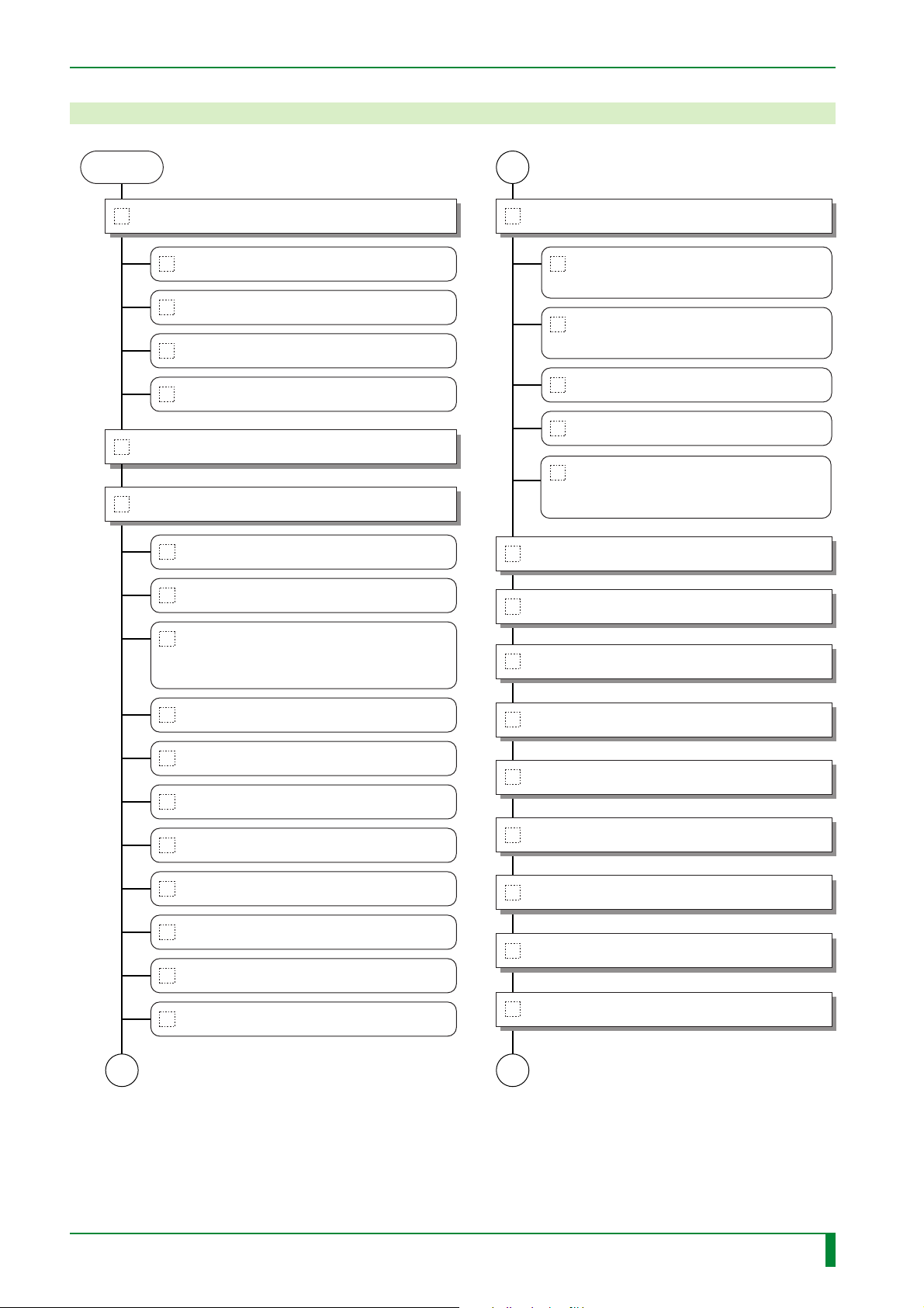
1. Work Flow
IN - 2
START
2. Preparation for Installation
2.2 Unpacking and Unloading
2.3 Transfer
2.4 Temporary Placement
2.5 Checking the Items Supplied
3. Removing the Covers
4. Unclamping
4.1 Front Shelf Cover (Front)
4.2 Pulling Out the Tray
A
5. Installing the Separate Packaged Items
5.1 Light-Collecting Guide Assembly
(for the Front)
5.2 Light-Collecting Guide Assembly
(for the Back)
5.3 Pushing In the Scanner Unit
5.4 Erasure Lamp Assembly
5.5 Memory Boards (Only for Machine
with Shipment Control Number of
5079 or Earlier)
6. Removing the Board Retaining Plate
7. Setting the Boards
4.3 Cassette Set Unit/IP Removal Unit
(Front/Right-Hand Side/Left-Hand
Side)
4.4 Pushing In the Tray
4.5 Subscanning Unit (Left-Hand Side)
4.6 Subscanning Unit (Rear)
4.7 Subscanning Unit (Right-Hand Side)
4.8 Pulling Out the Scanner Unit
4.9 Subscanning Unit (Front)
4.10 Subscanning Unit (Inside)
4.11 Side-Positioning Conveyor (Rear)
A
8. Installing the Boards
9. Installing the Board Retaining Plate
10. Connecting the Interface Cables
11. Turning OFF the High-Voltage Switch
12. Connecting the Power Cable
13. Checking the Resistance Values
14. Powering ON
B
FR7H7001.EPS
009-058-03
08.30.2002 FM3476
CR-IR347
Service Manual
IN - 2
Page 8
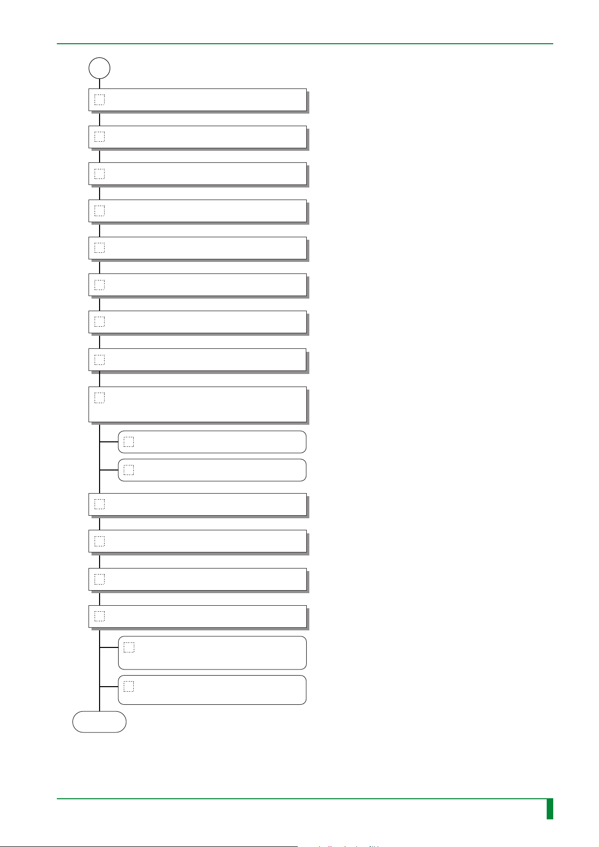
B
15. Checking the Fan Operation
16. Measuring and Adjusting the Voltage
17. Clearing the Backup Memory
18. Setting the Date and Time
19. Turning ON the High-Voltage Switch
20. Installing the Covers
21. Setting the Configuration
IN - 3
22. Checking for Image Problems
23. Checking and Deleting the Error Log
during Setup
23.1 Checking the Error Log
23.2 Deleting the Error Log
24. Powering OFF
25. Cleaning the Covers
26. Attaching the Labels
27. Final Placement
27.1 Securing the Machine with the
Adjustable Feet
END
009-058-03
08.30.2002 FM3476
27.2 Securing the Machine with the
Clamps
FR7H7002.EPS
CR-IR347
Service Manual
IN - 3
Page 9

2. Preparation for Installation
■ Notation of Board Names in Manual
Information about modifications to the boards installed in the machine is summarized here.
Unless spelled out or enumerated in the manual, board names shall be replaced as follows.
IN - 4
Change to boards installed
MTH08C → MTH08D
MMA90A → DIM08A
MMB90A → DIM08A
CPU90F → LAN90B
Summary of change
● Features of the MTH08D board
• DIP switch (S1) was added.
• The fuse was changed to a replaceable glass tube type.
• The subject to be protected by the fuse was changed.
● Features of the DIM08A board
• Memory module for the MTH08D board.
• The procedure for its removal/reinstallation was changed
to horizontal detachment.
• Shipped as installed in the machine.
● Features of the LAN90B board
• To install the LAN90B board, it is necessary that the bracket
located on the rear side of the controller be version D or later.
TR7H7022.EPS
009-058-03
08.30.2002 FM3476
CR-IR347
Service Manual
IN - 4
Page 10
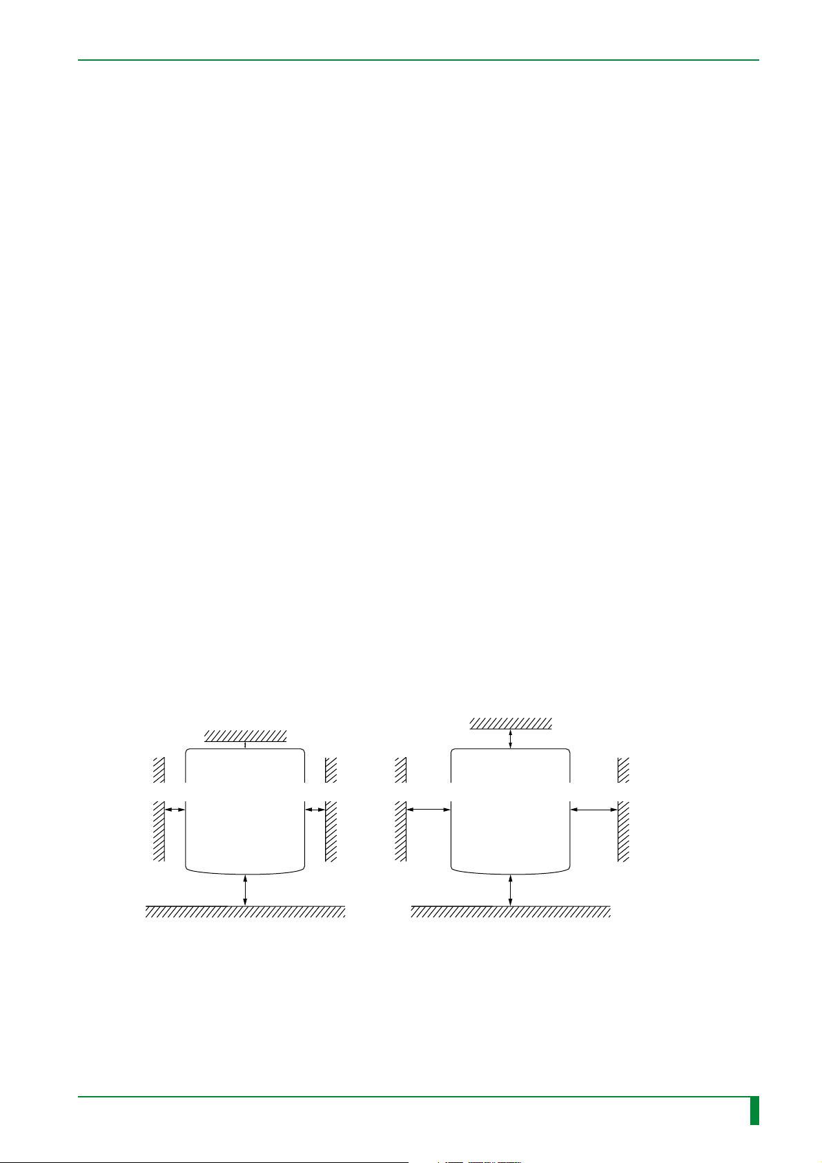
2.1 Precautions for Installation
The place where the machine is to be installed needs to meet the criteria set forth in “Getting
Started” and “■ Installation Site Requirements.” Preinstallation procedures should also be
performed beforehand for necessary construction work, electrical utility, and air-conditioning
system installation.
■ Installation Site Requirements
Avoid the following installation sites:
• Places where the temperature changes drastically.
• Places near heat sources such as heaters.
• Places where water leakage or equipment submersion may occur.
• Places where the machine may be exposed to any corrosive gas.
• Dusty places.
• Places where the machine is subject to constant or excessive vibration or shock.
• Places that are exposed to direct sunlight.
IN - 5
■ Power Supply and Grounding Requirements
When the 200-240 VAC power supply is used, a circuit breaker rated over 250V/20A should
be provided for the single power supply of the CR-IR347. For grounding, the machine
should be connected to the protective ground line of the indoor wiring.
■ Handling Precautions for Printed Circuit Boards and Scanning Optics Unit
When servicing a printed circuit board or scanning optics unit, be sure to wear an antistatic
wristband to ground your body. If your body is not grounded, static electricity built on your
body may cause damage to the electronic parts.
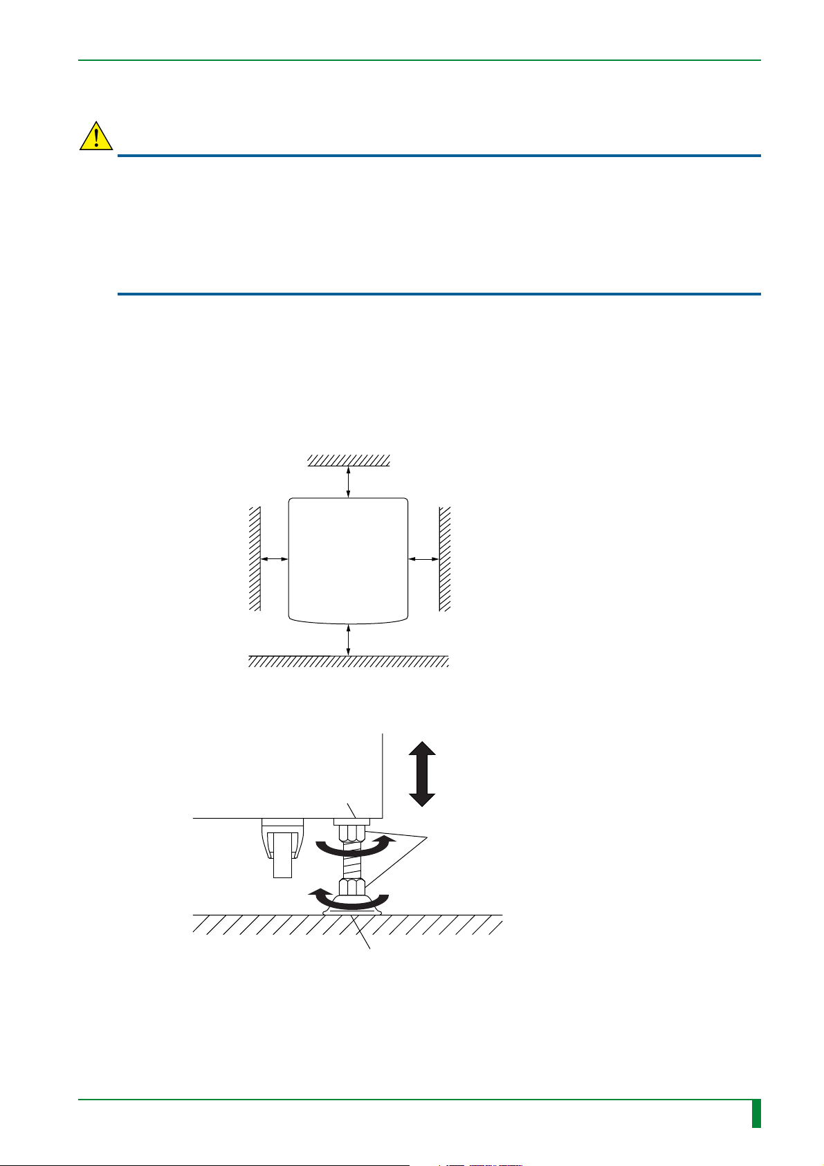
■ Check for Installation Space
When not secured by the clamps When secured by the clamps
Height: 1800 or more
Rear
Machine
50 or more
Height: 1800 or more
Rear
700 or more 700 or more200 or more 200 or more
100 or more
Machine
009-058-03
08.30.2002 FM3476
Front
700 or more
CR-IR347
Front
Service Manual
700 or more
Unit: mm
FR7H7003.EPS
IN - 5
Page 11
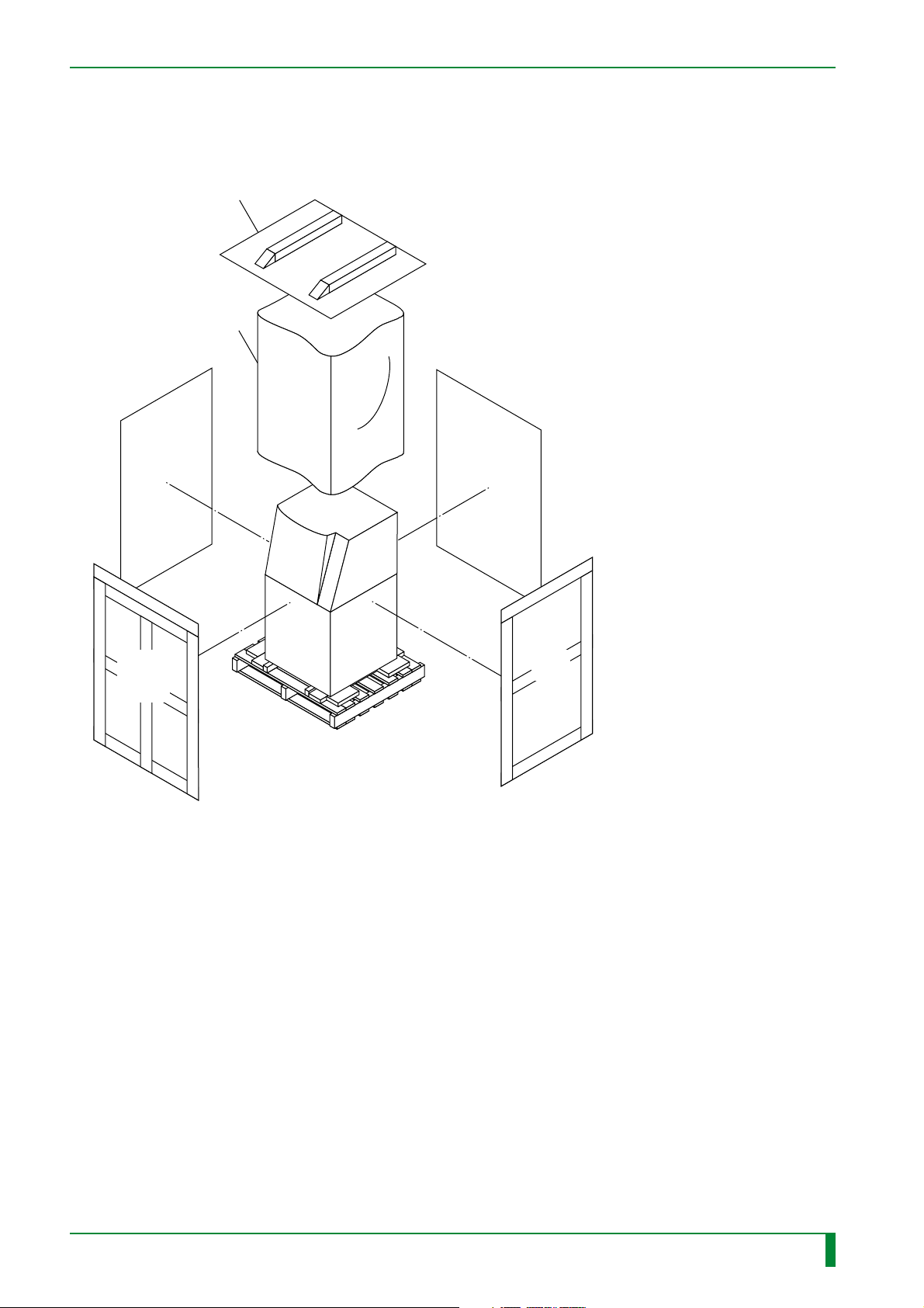
2.2 Unpacking and Unloading
■ Unpacking
Top protective cover
(Placed upside down
for use as slope)
Moisture-proof sheet
IN - 6
Wooden
crate piece
Wooden
crate
piece
Wooden
crate piece
Wooden
crate
piece
Carrier pallet
FR7H7203.EPS
009-058-03
08.30.2002 FM3476
CR-IR347
Service Manual
IN - 6
Page 12
2.3 Transfer
CAUTIONS
• When the machine is transferred with its casters, be sure to raise the adjustable feet of the
machine all the way up.
• When bringing the machine into the installation place, support it so that it will not topple down.
Because the machine is top-heavy, it may topple during transit.
• If the machine should be moved over some step or bump, move it as slowly as possible to
avoid shock to it. Note that the step over which the machine may move over is about 10 mm
high at most.
Bring the machine into the installation place.
2.4 Temporary Placement
(1) Secure space required for installation procedures and temporarily place the machine.
Height: 1900 or more
IN - 7
Rear
600 or more
Front
700 or more
Machine
700 or more
700 or more
Unit : mm
FR7H7016.EPS
(2) Secure the machine with the adjustable feet in place
Machine
Seating face on the frame side
[Secure] Nut (x4)
009-058-03
08.30.2002 FM3476
Adjustable foot
CR-IR347
FR7H7017.EPS
Service Manual
IN - 7
Page 13
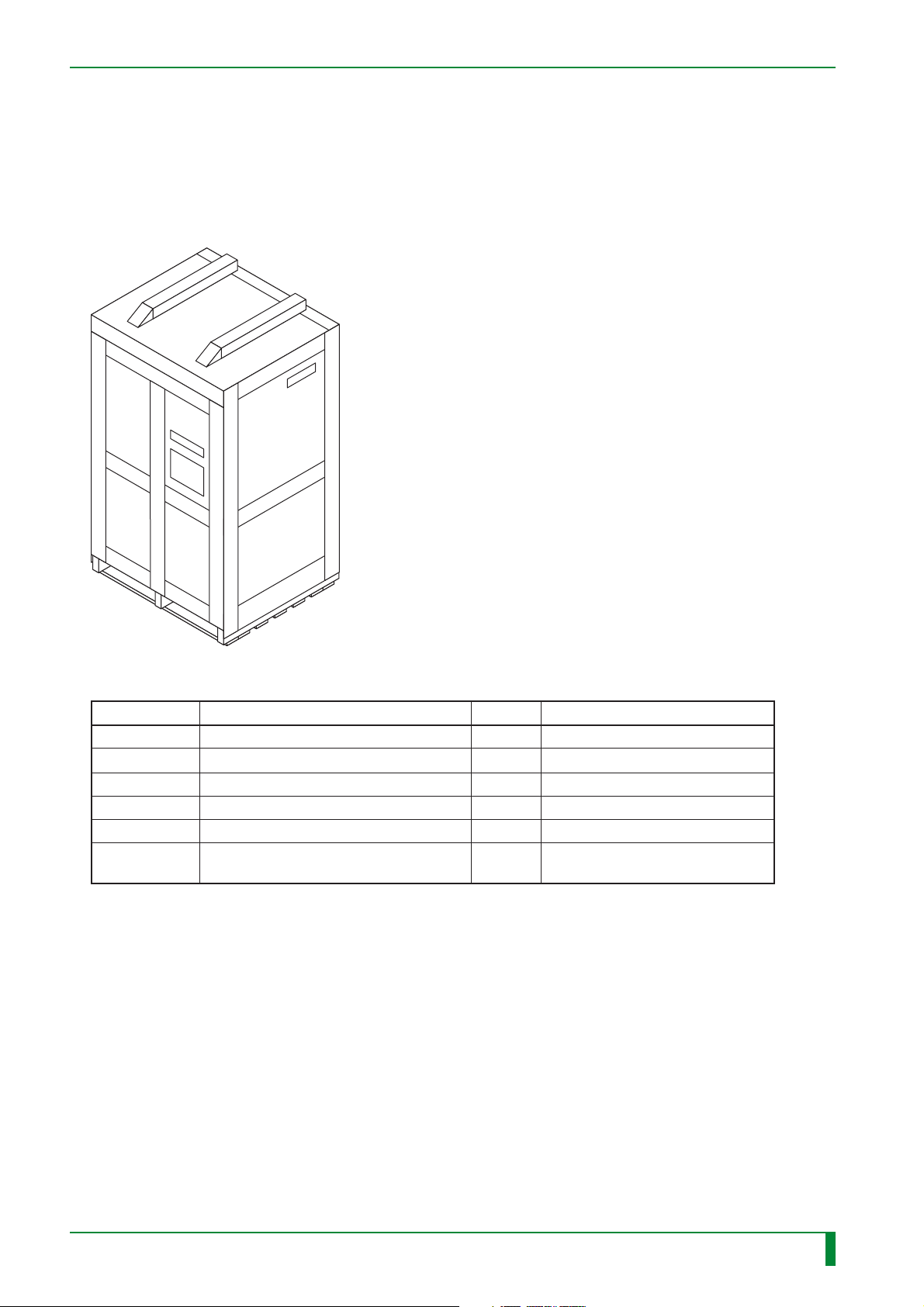
2.5 Checking the Items Supplied
Check whether all the items are supplied in accordance with the packing list that is contained
in each carton. The service technician must keep the test result sheet.
■ Machine Main Body
IN - 8
FR7H7015.EPS
Check Item Qty. Remarks
Machine main body
Clamps 4
CPU90E board (installed in the machine)
IMG07B board (installed in the machine)
BSP08A board (installed in the machine)
DIM08A board (installed in the machine)
1
1
1
1
2
Only for machine with shipment
control number of 5080 or later
TR7H7008.EPS
009-058-03
08.30.2002 FM3476
CR-IR347
Service Manual
IN - 8
Page 14
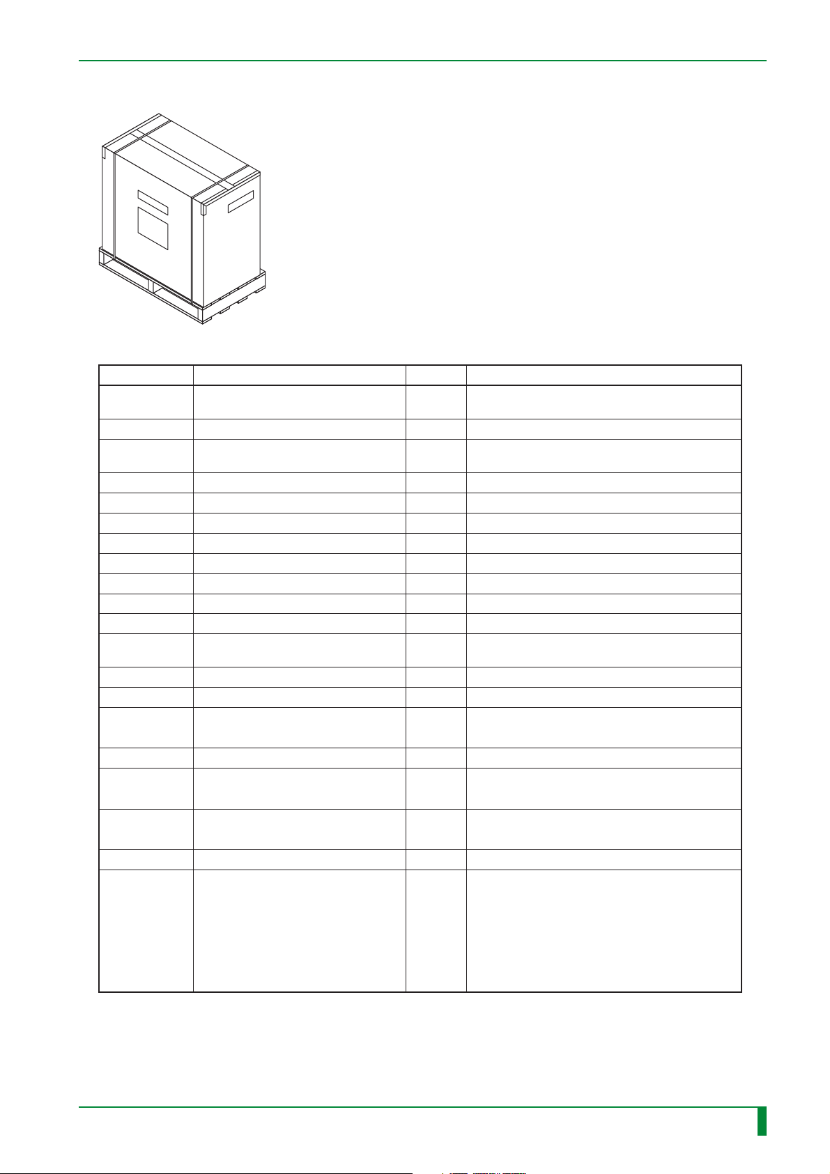
■ Separate Packaged Items
FR7H7111.EPS
Check Item Qty. Remarks
Instruction Manual (for the
machine main body)
Test Result Sheet
Floppy diskette (for machinespecific data)
Floppy diskette (PC MENU EDITOR)
Label
Hex head bolt (SUS 12x25)
Grip anchor (M12x50)
Spring washer (M12)
Plain washer (M12)
NK clamp (NK-18N, 13N, 10N)
T4x8 For installing the optional board
BR4x8
T4x12
T4x20
Memory boards
(MMA90A and MMB90A)
1
1
1
1 set
1 set
8
8
8
8
4 for each
6
3
4
2
1 for each
IN - 9
For installing the erasure lamp assembly.
Two for spare.
For upper front cover and lower front cover
For retaining the interface cable (rear cover)
Only for machine with shipment control number
of 5079 or earlier
009-058-03
08.30.2002 FM3476
Erasure lamp assembly
Light-collecting guide assembly
(for the front)
Light-collecting guide assembly
(for the back)
FUJI FILM Warranty Sheet
Power cable kit
• 100-200 V spec for Japan and
US
• 100 V spec for Japan (JIS
patient environment supported)
• 200-240 V spec for Europe
(excluding UK)
• 200-240V spec for UK
CR-IR347
1
1
1
1
1
(either
model)
Service Manual
TR7H7009.EPS
IN - 9
Page 15

■ Optional Items
IN - 10
Check
Item
IMG08M board
IMG08H board
HCP08A board
CPU90F/LAN90B board
Qty.
1
1 or 2
1
1
Remarks
LP interface board
• High-speed multi-frequency processing (MFP) board
• High-speed mammography pattern enhancement (PEM) board
Compression/decompression processing board
Ethernet board, 100Base-TX Intelligent LAN board
TR7H7010+.EPS
009-058-03
08.30.2002 FM3476
CR-IR347
Service Manual
IN - 10
Page 16

BLANK PAGE
IN - 11
009-058-00
10.20.2000 FM2732 (2)
CR-IR347
Service Manual
IN - 11
Page 17
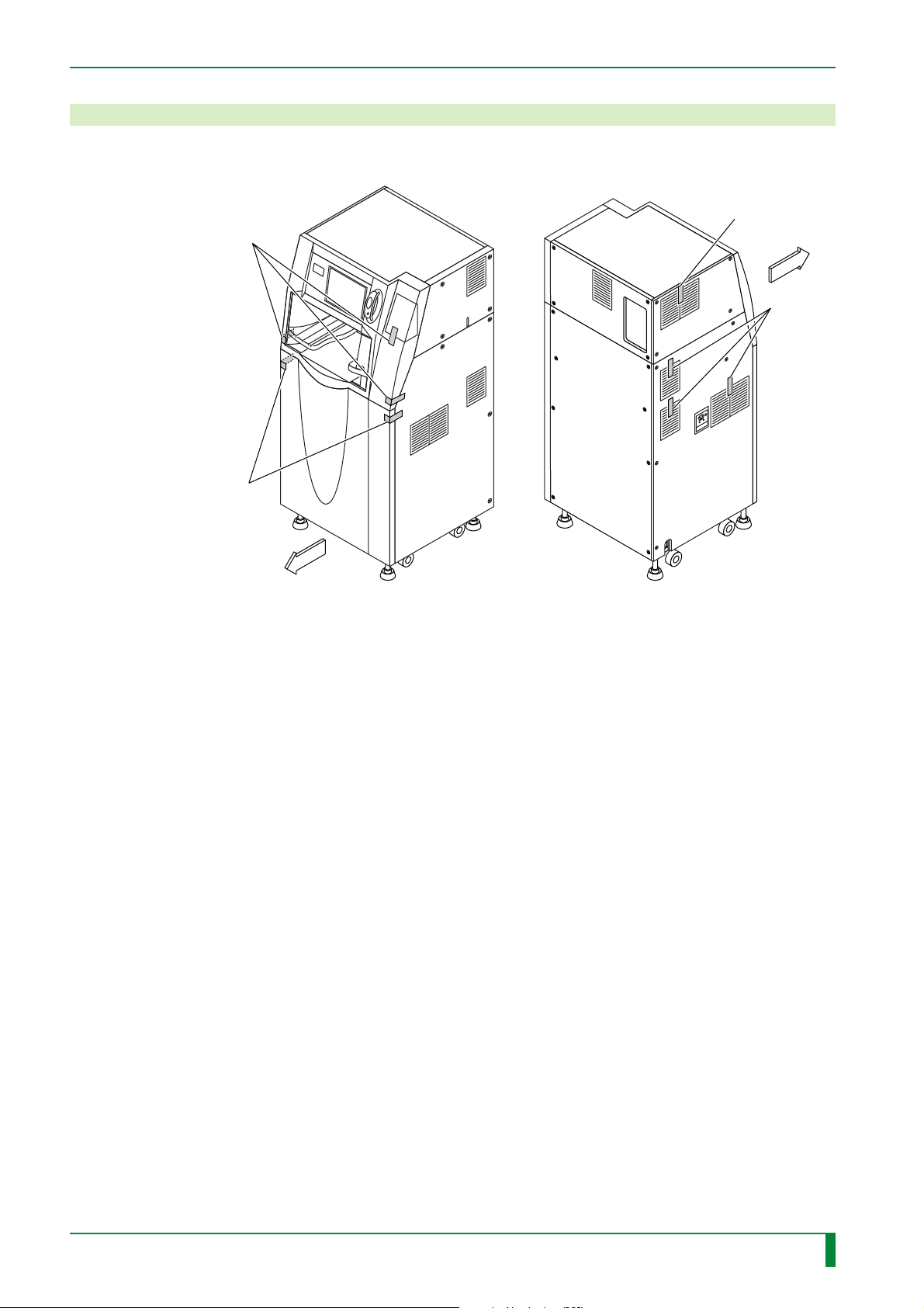
3. Removing the Covers
(1) Remove the tapes.
[Remove]
Tape (x3)
[Remove]
Tape (x2)
IN - 12
[Remove]
Tape
FRONT
[Remove]
Tape (x3)
FRONT
FR7H7104.EPS
009-058-00
10.20.2000 FM2732 (2)
CR-IR347
Service Manual
IN - 12
Page 18
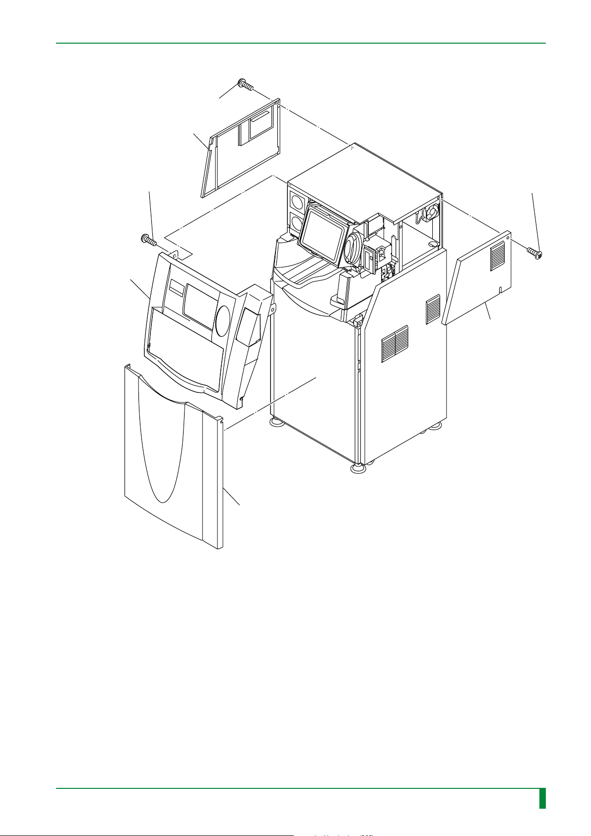
(2) Remove the covers.
[Remove] T4x12 (x4)
Upper left-hand side cover
IN - 13
#1
[Remove] BR4x8 (x2)
Upper front cover
#3
#2
[Remove]
T4x6 (x4)
Upper right-hand
side cover
Lower front cover
FR7H7112.EPS
009-058-00
10.20.2000 FM2732 (2)
CR-IR347
Service Manual
IN - 13
Page 19
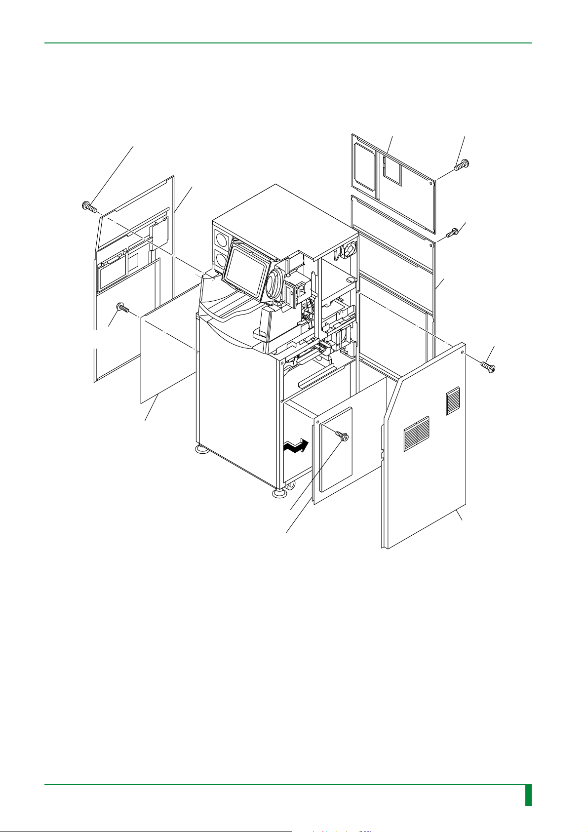
IN - 14
#9
[Remove]
BR4x8 (x6)
Left-hand side inner cover
#8
[Remove] T4x12 (x6)
T4x6 (x3)
Lower left-hand
side cover
Upper rear cover
Lower rear cover
#6 [Remove]
T4x12 (x4)
#7 [Remove]
T4x12 (x8)
#4 [Remove]
T4x6 (x7)
009-058-00
10.20.2000 FM2732 (2)
#5
[Remove] BR4x8 (x5)
Right-hand side inner cover
CR-IR347
Service Manual
Lower right-hand
side cover
FR7H7113.EPS
IN - 14
Page 20

BLANK PAGE
IN - 15
009-058-00
10.20.2000 FM2732 (2)
CR-IR347
Service Manual
IN - 15
Page 21
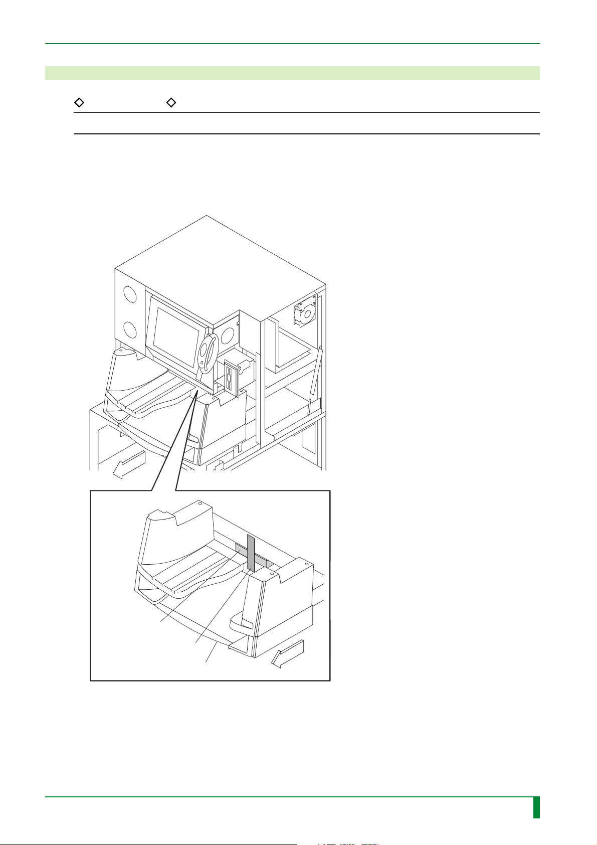
4. Unclamping
REFERENCE
For unclamping, the procedures may be performed along the string attached to the clamps.
4.1 Front Shelf Cover (Front)
Unclamp the clamps.
IN - 16
FRONT
[Remove]
Foam block
[Remove] Tape
Front shelf cover
FRONT
FR7H7020.EPS
009-058-00
10.20.2000 FM2732 (2)
CR-IR347
Service Manual
IN - 16
Page 22
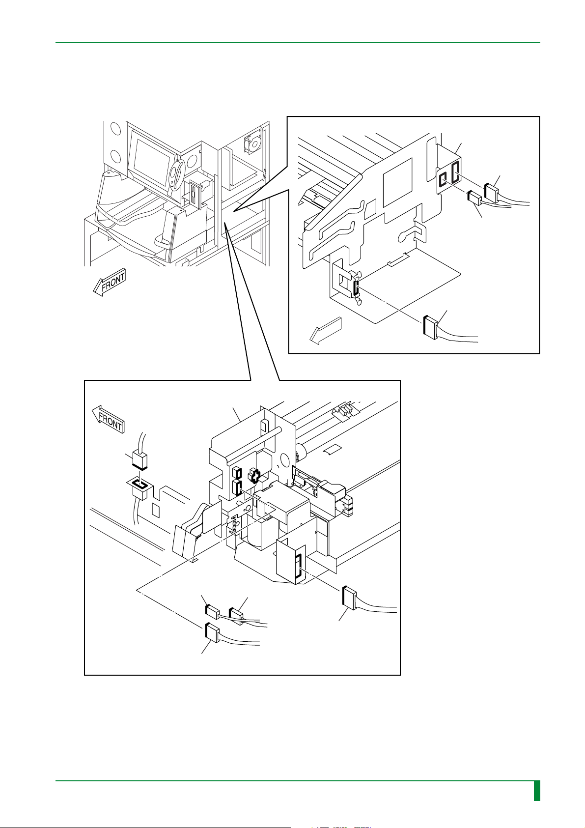
4.2 Pulling Out the Tray
(1) Disconnect the connectors.
IN - 17
[Disconnect] Connectors
IP removal unit
CNL2
CNL3
CNL1
[Disconnect] Connectors
Cassette set unit
CNU1
CNK1
FRONT
CNSOLK1
009-058-00
10.20.2000 FM2732 (2)
CNK2
CR-IR347
BCR08A CN1
Service Manual
FR7H7117.EPS
IN - 17
Page 23
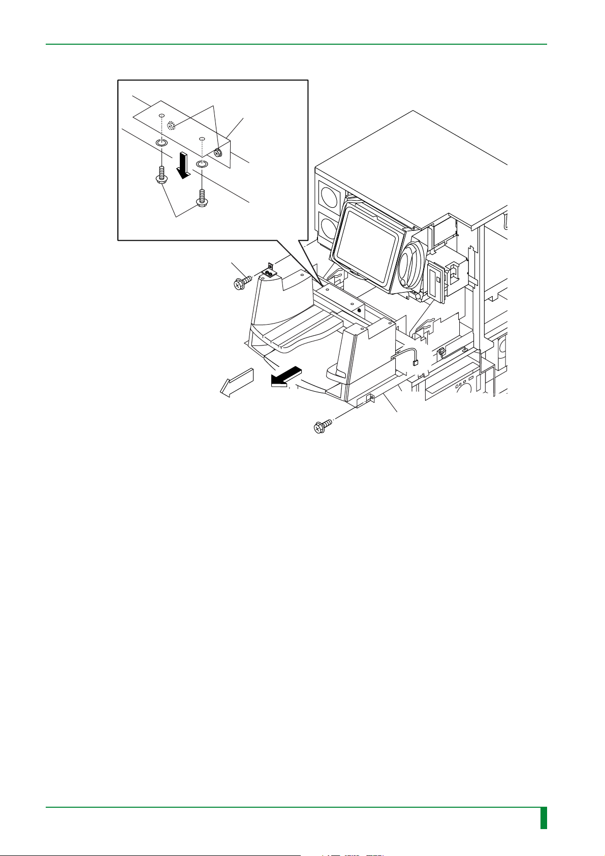
(2) Pull out the tray.
#1 [Loosen] BR4x8 (x2)
#2 [Remove] BR4x8 (x2), W6
[Remove] BR4x8 (x2)
IN - 18
Bracket
#3
FRONT
#4
[Pull-out] Tray
FR7H7019.EPS
009-058-00
10.20.2000 FM2732 (2)
CR-IR347
Service Manual
IN - 18
Page 24
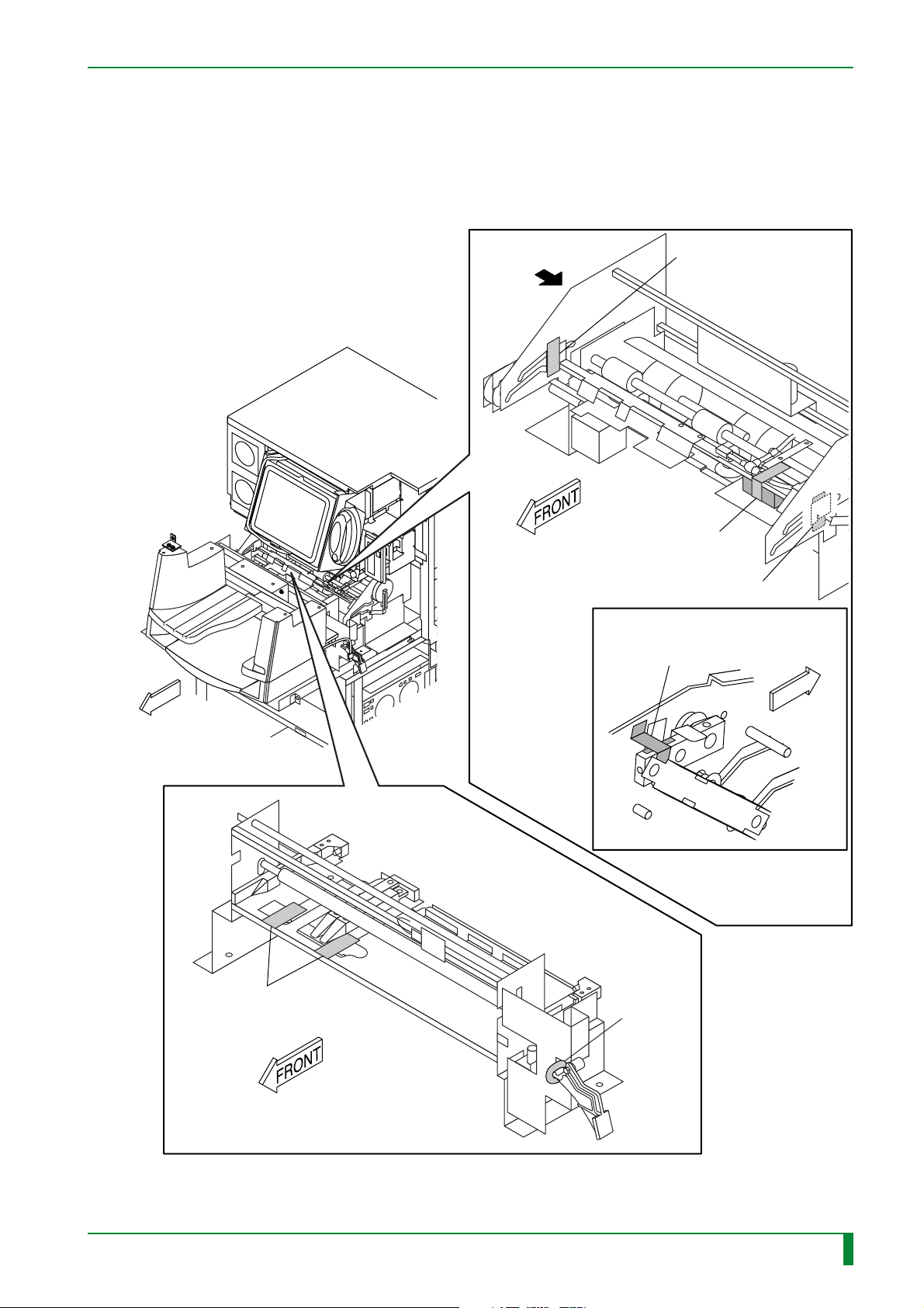
IN - 19
4.3 Cassette Set Unit/IP Removal Unit (Front/Right-Hand Side/ Left-Hand Side)
Unclamp the clamps.
IP removal unit
FRONT
A
[Remove] Tape
[Remove]
Tape and foam block
[Remove]
Tape
DETAIL A
[Remove] Tape and corrugated board
FRONT
Cassette set unit
[Remove]
Tape (x2)
[Cut]
Cable tie
FR7H7105.EPS
009-058-00
10.20.2000 FM2732 (2)
CR-IR347
Service Manual
IN - 19
Page 25
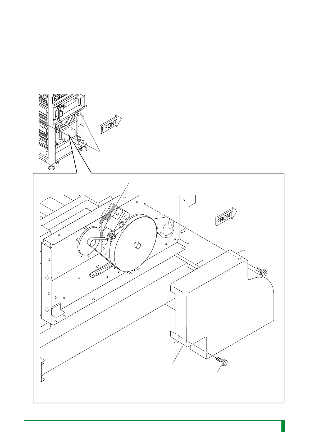
4.4 Pushing In the Tray
By reversing the procedures for pulling out the tray, push in the tray.
4.5 Subscanning Unit (Left-Hand Side)
Unclamp the clamps.
HHS label #2
IN - 20
#2
[Remove] Tape and foam block
009-058-00
10.20.2000 FM2732 (2)
Transparent cover
CR-IR347
Service Manual
#1
[Remove] BR4x8 (x2)
#3
[Attach] BR4x8 (x2)
FR7H7022.EPS
IN - 20
Page 26
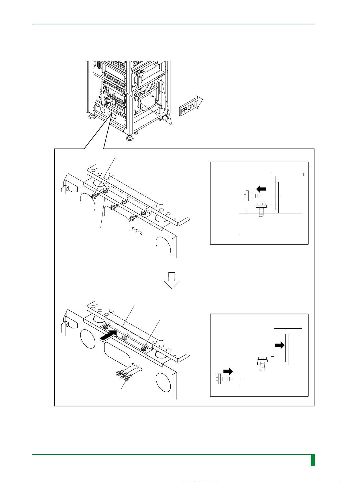
4.6 Subscanning Unit (Rear)
Slide the subscanning unit retaining bracket.
#1
[Remove] BR5x8 (x3)
IN - 21
HHS label #2
#2
[Loosen]
BR5x8 (x3)
#5 [Attach]
BR5x8 (x3) removed at #1
#3
[Slide] Bracket
#4
[Tighten] BR5x8 (x3)
009-058-00
10.20.2000 FM2732 (2)
CR-IR347
Service Manual
FR7H7202.EPS
IN - 21
Page 27
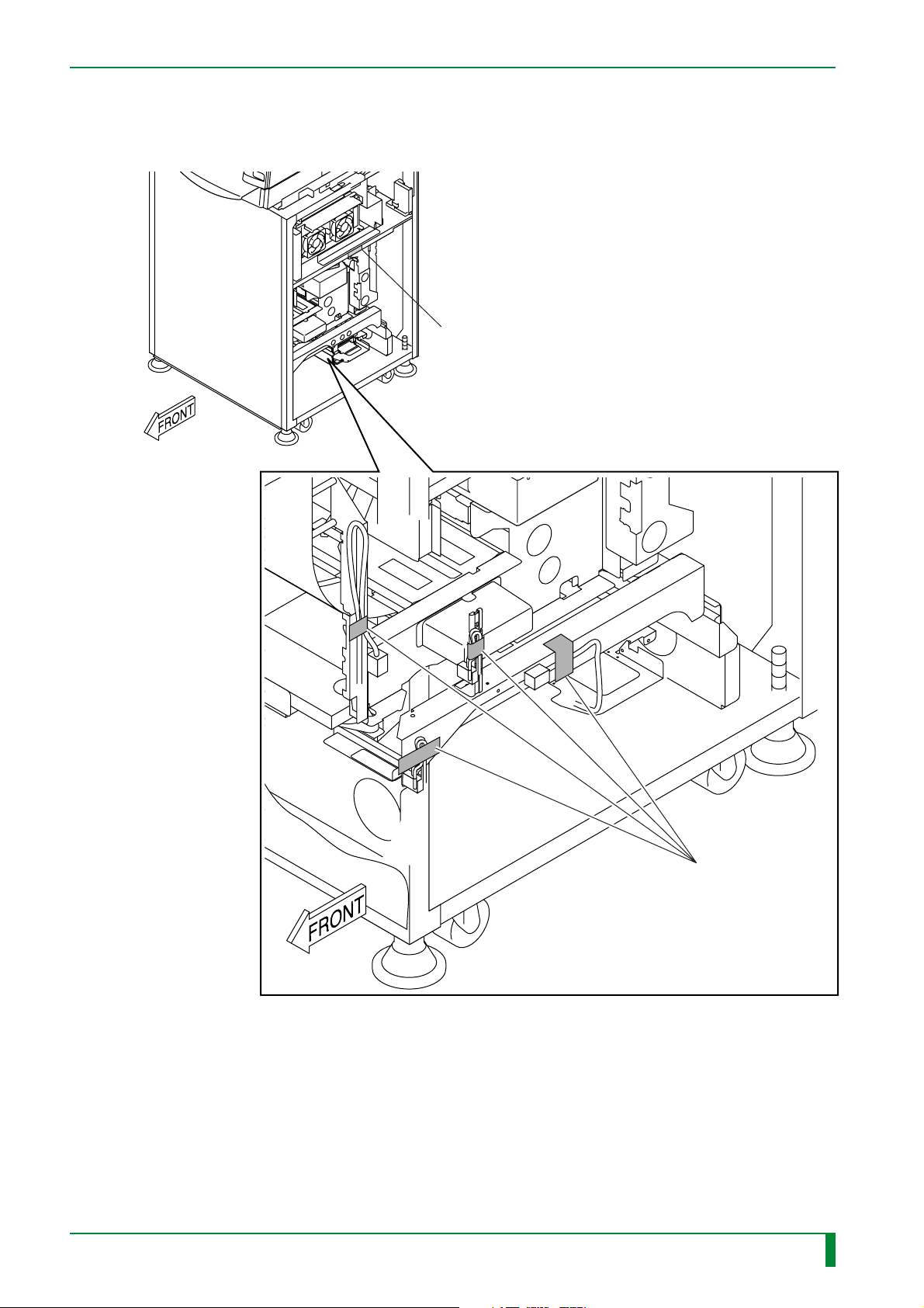
4.7 Subscanning Unit (Right-Hand Side)
Remove the tapes.
HHS label #2
IN - 22
009-058-00
10.20.2000 FM2732 (2)
CR-IR347
Service Manual
[Remove] Tape (x4)
FR7H7118.EPS
IN - 22
Page 28

BLANK PAGE
IN - 23
009-058-00
10.20.2000 FM2732 (2)
CR-IR347
Service Manual
IN - 23
Page 29
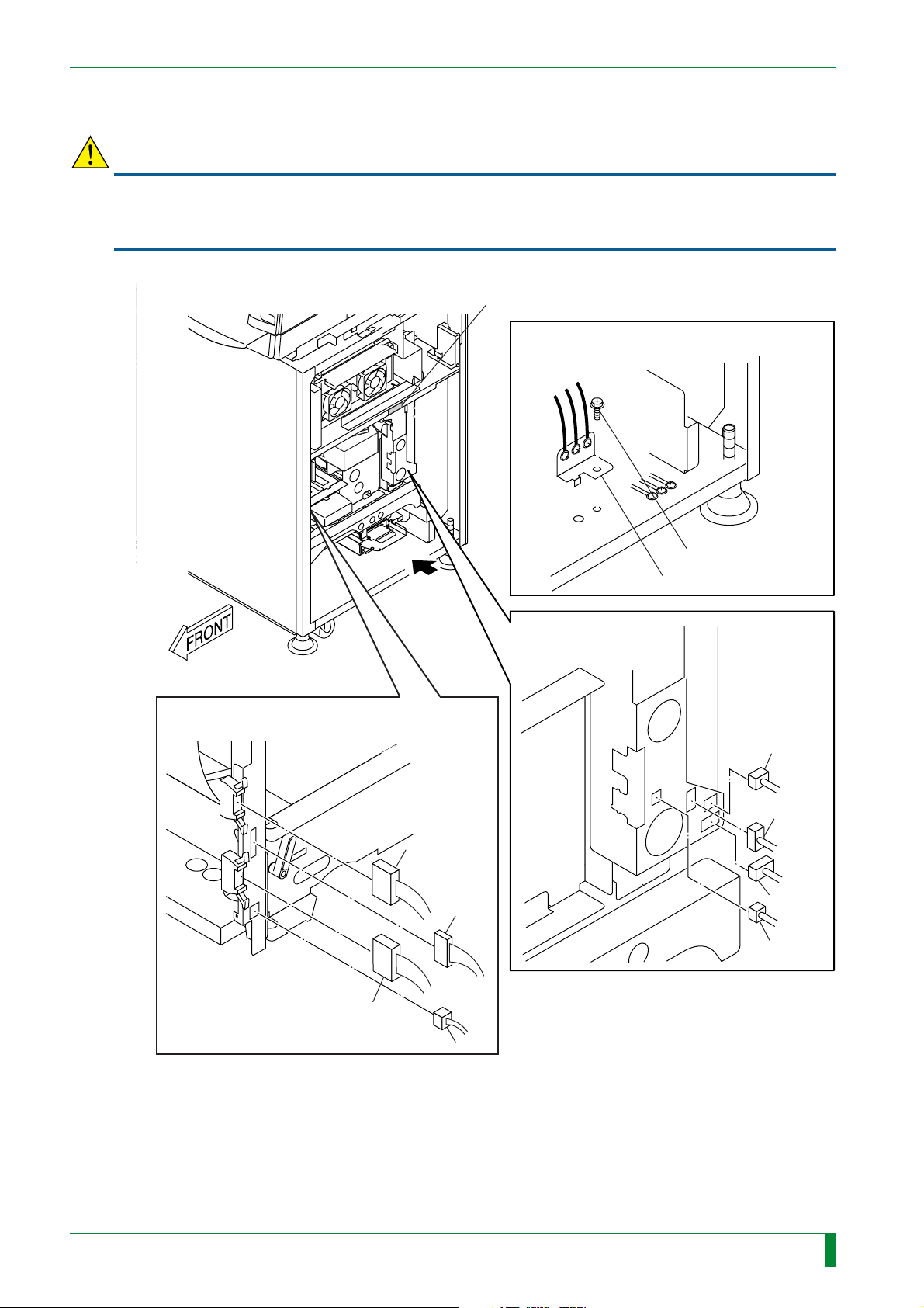
4.8 Pulling Out the Scanner Unit
CAUTION
When servicing any printed circuit board, be sure to wear an antistatic wristband to ground your
body. If your body is not grounded, static electricity built on your body may cause damage to
electronic parts on the board.
(1) Disconnect the connectors.
HHS label #2
DETAIL A
#5005 or later
IN - 24
#1
[Disconnect] Connectors
[Remove] BR4x8
Bracket
A
#2
[Disconnect] Connectors
CN-Z6
CN-Z7
CN-Z2
CN-Z5
CN-Z1
CN-Z8
009-058-00
009-058-02
10.20.2000 FM2732 (2)
08.30.2001 FM3142
CN-Z3
CR-IR347
CN-Z4
Service Manual
FR7H7227.EPS
IN - 24
Page 30
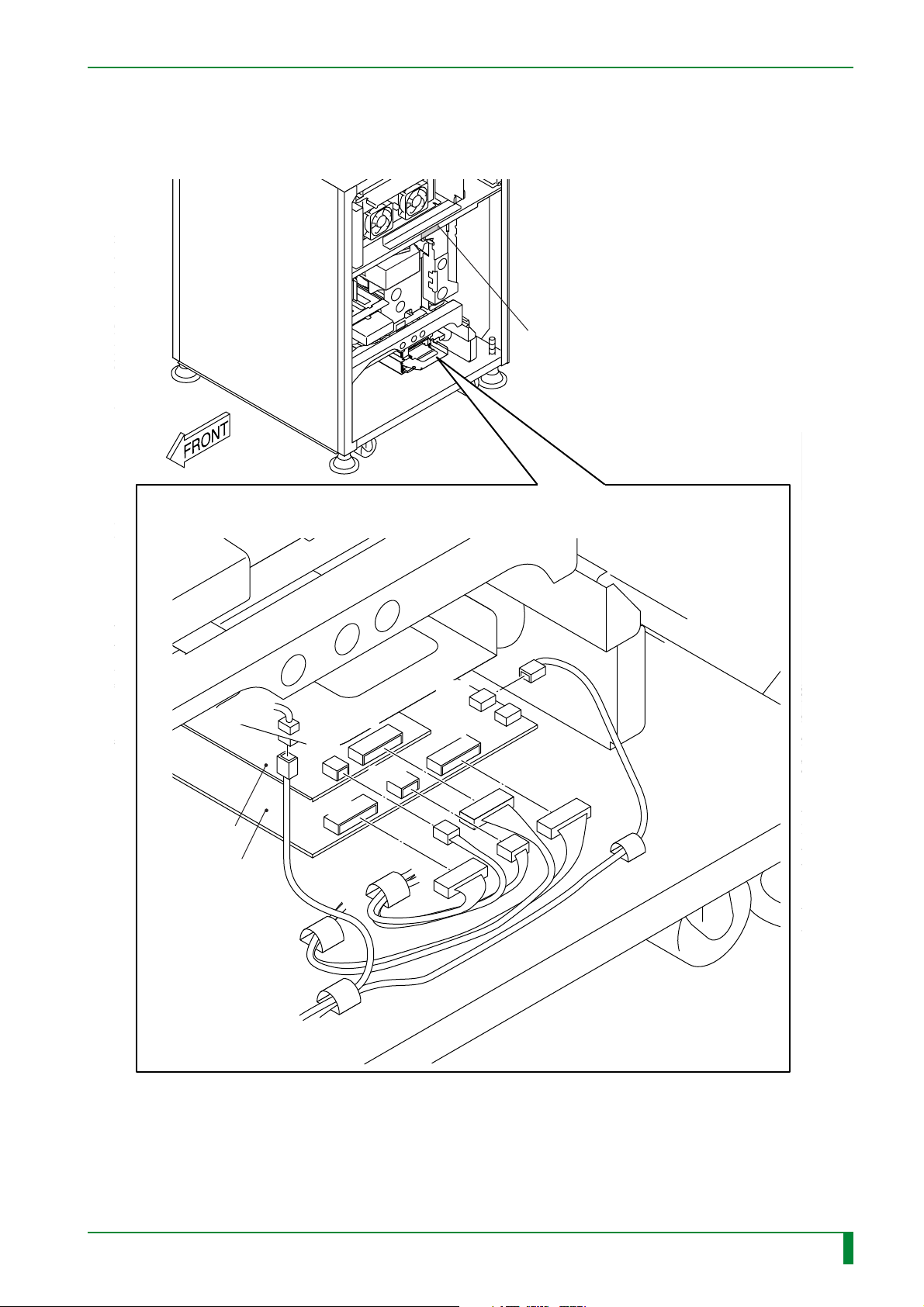
#3
[Disconnect] Connectors
IN - 25
HHS label #2
CN-Z12
SCR08D board
SCN08D board
CN3
CN8
CN6
CN9
CN7
CN12
FR7H7228.EPS
009-058-00
10.20.2000 FM2732 (2)
CR-IR347
Service Manual
IN - 25
Page 31
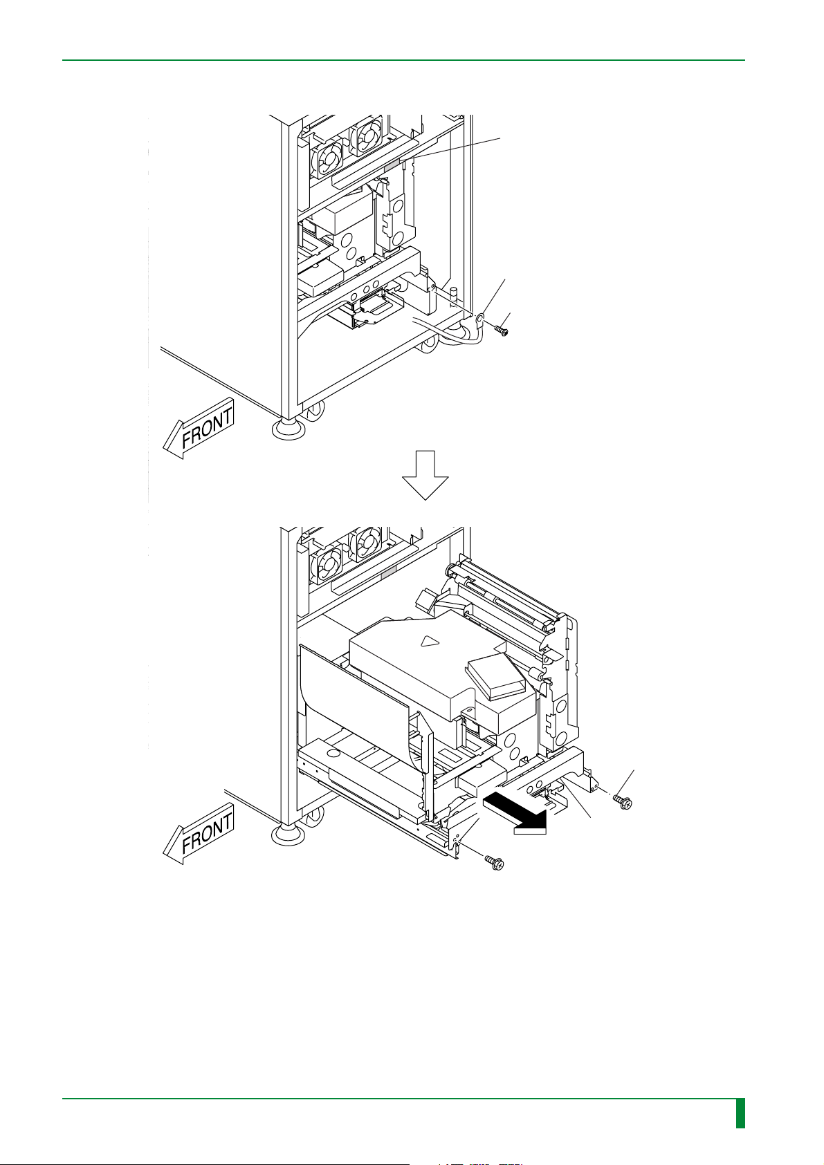
(2) Pull out the scanner unit.
IN - 26
HHS Label #2
Ground
#1
[Remove] CS4x8
009-058-00
10.20.2000 FM2732 (2)
CR-IR347
Service Manual
#2
[Remove]
BR4x8 (x2)
#3
[Pull-out] Scanner unit
FR7H7229.EPS
IN - 26
Page 32

BLANK PAGE
IN - 27
009-058-00
10.20.2000 FM2732 (2)
CR-IR347
Service Manual
IN - 27
Page 33
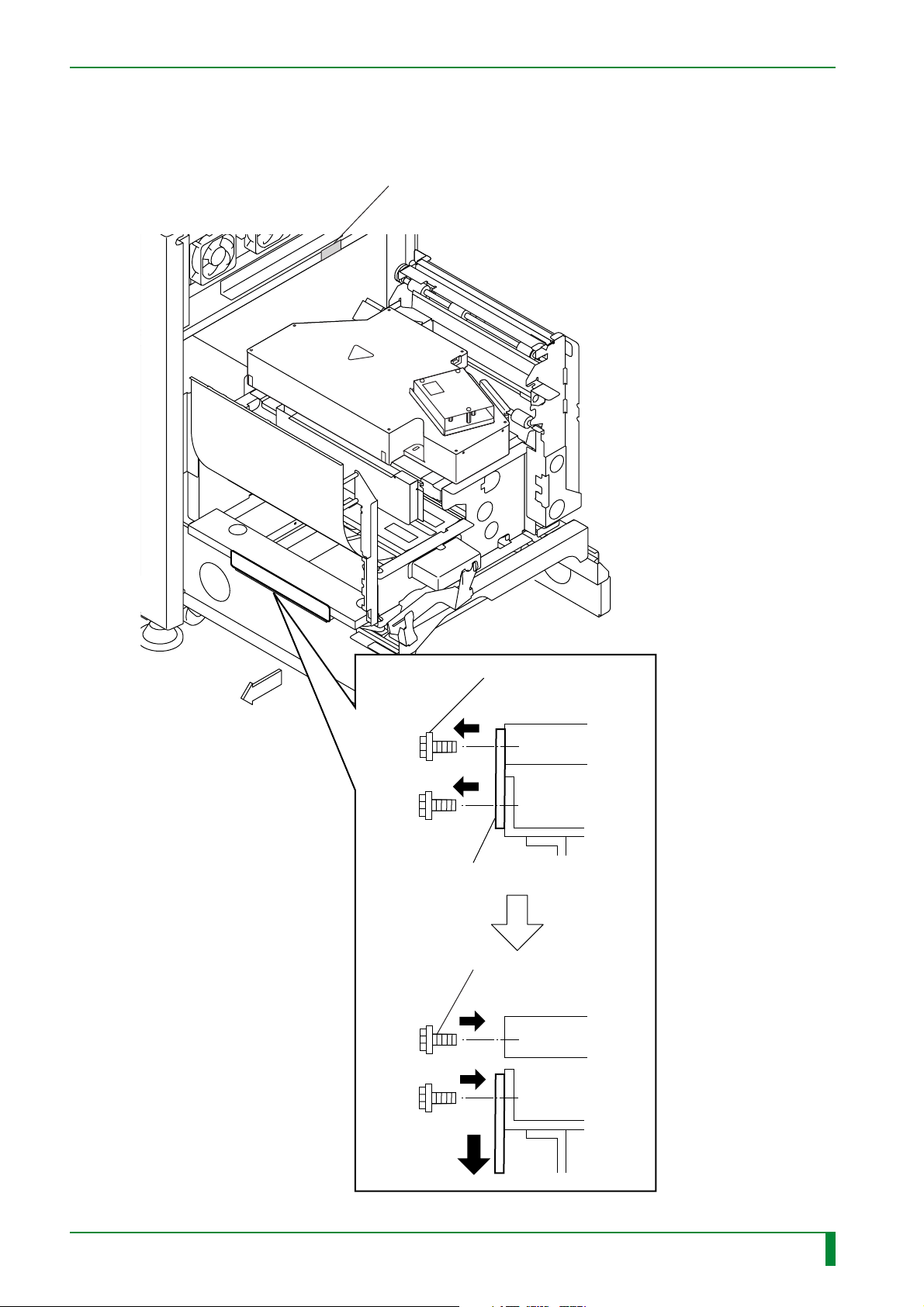
4.9 Subscanning Unit (Front)
Reposition the retaining bracket.
HHS label #2
IN - 28
FRONT
#1
[Remove] BR5x8 (x6)
Retaining bracket
#2
[Attach] BR5x8 (x6)
009-058-00
10.20.2000 FM2732 (2)
CR-IR347
Service Manual
FR7H7200.EPS
IN - 28
Page 34
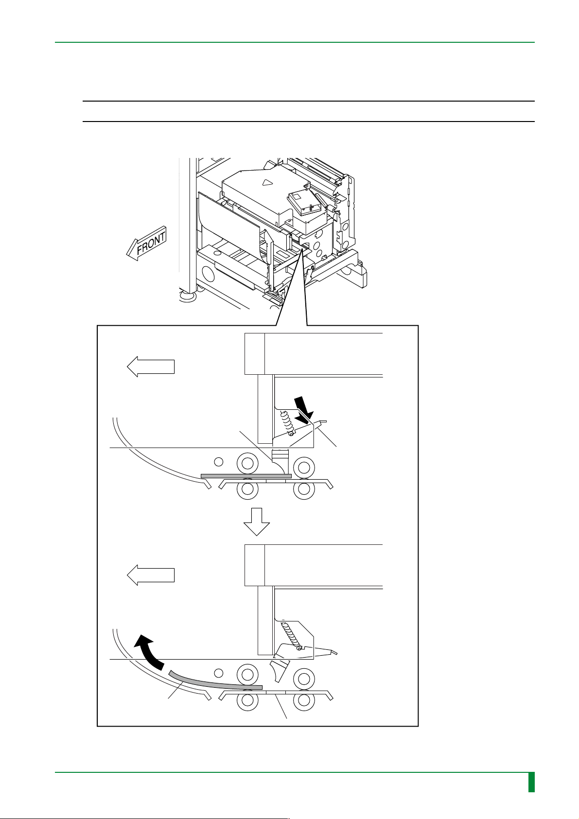
4.10 Subscanning Unit (Inside)
◆
NOTE
Use care not to damage the light-collecting mirror and glass guide.
Remove the foam block.
◆
IN - 29
FRONT
Light-collecting mirror
FRONT
#1
[Push] Bracket
009-058-00
10.20.2000 FM2732 (2)
#2
[Remove]
Foam block
CR-IR347
Glass guide
Service Manual
FR7H7201.EPS
IN - 29
Page 35
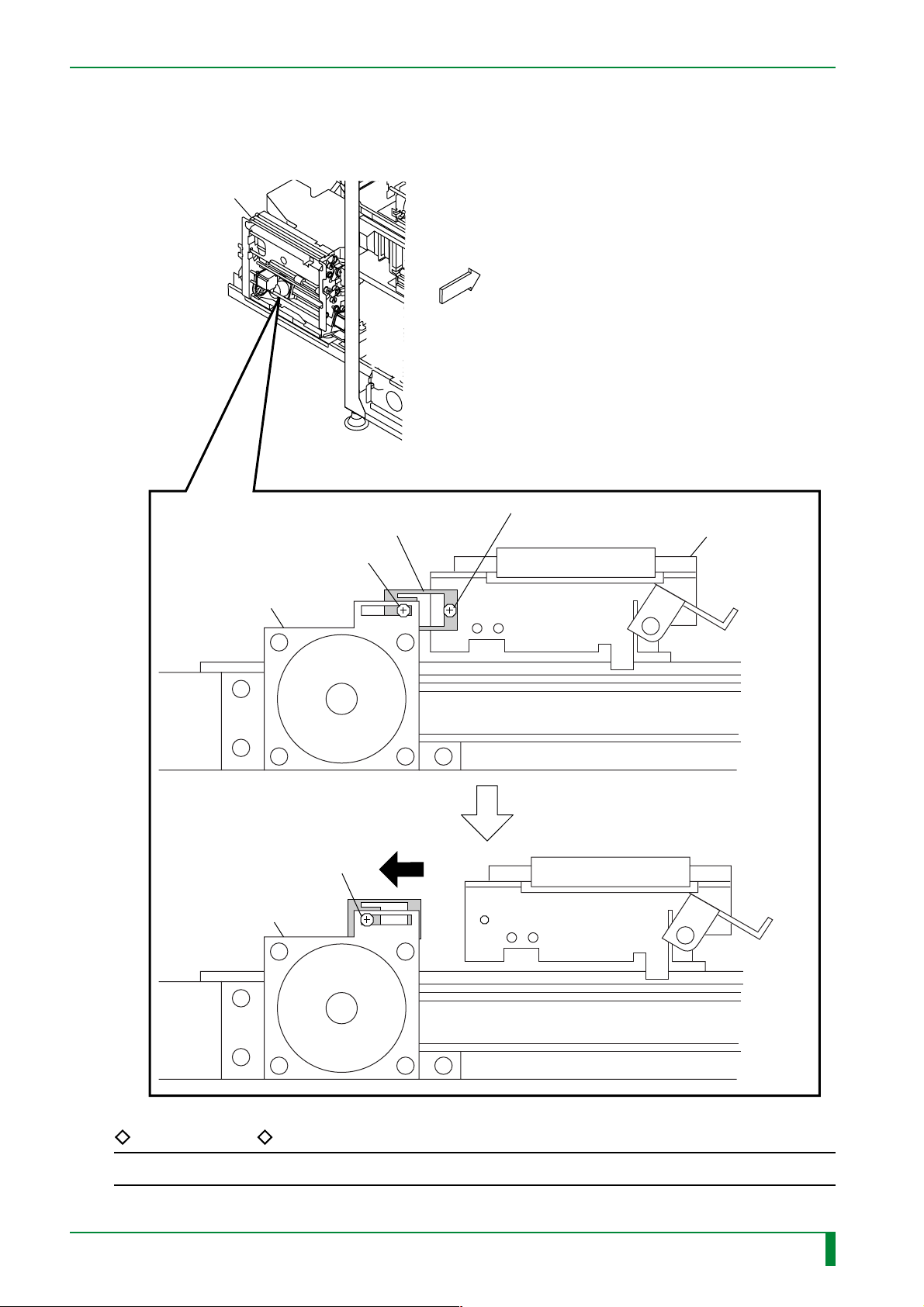
4.11 Side-Positioning Conveyor (Rear)
Reposition the clamp member.
Side-positioning
conveyor
FRONT
IN - 30
Clamp member
[Loosen] BR4x8
MN1
#3
[Tighten] BR4x8
MN1
#2
#1
[Remove] BR4x8 (kept for later use)
Side-positioning
member
REFERENCE
The screw removed should be kept separately for later use.
009-058-00
10.20.2000 FM2732 (2)
CR-IR347
Service Manual
FR7H7021.EPS
IN - 30
Page 36
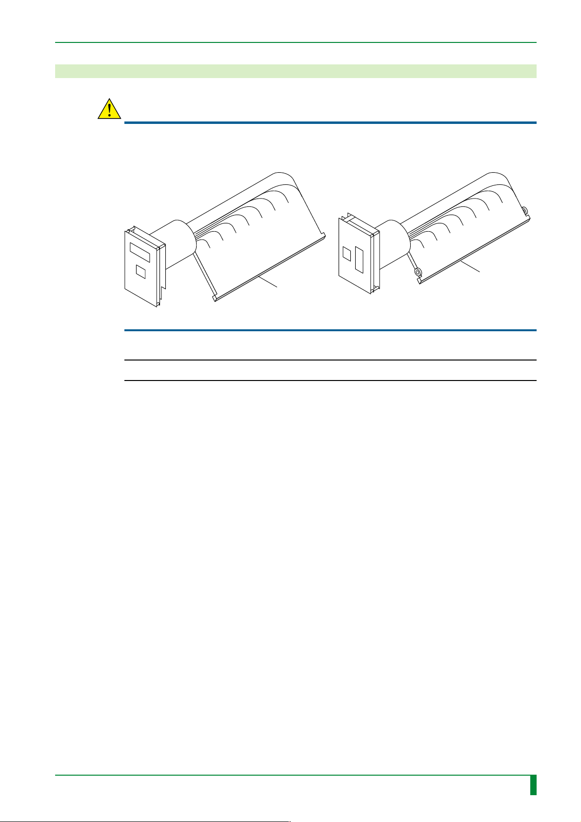
5. Installing the Separate Packaged Items
CAUTION
Never touch the incidence surface of the light-collecting guide even when you wear
gloves.
IN - 31
Light-collecting guide assembly
(for the front)
◆
INSTRUCTION
◆
Light-receiving face
Light-collecting guide assembly
(for the back)
When handling the light-collecting guide assembly, wear gloves.
Light-receiving face
FR7H7029.EPS
009-058-00
10.20.2000 FM2732 (2)
CR-IR347
Service Manual
IN - 31
Page 37
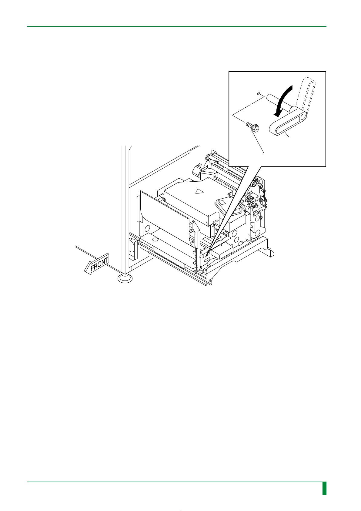
5.1 Light-Collecting Guide Assembly (for the Front)
(1) Rotate the lever counterclockwise.
#1
[Remove] BR4x8
IN - 32
#2
[Rotate] Lever
FR7H6144.EPS
009-058-00
10.20.2000 FM2732 (2)
CR-IR347
Service Manual
IN - 32
Page 38
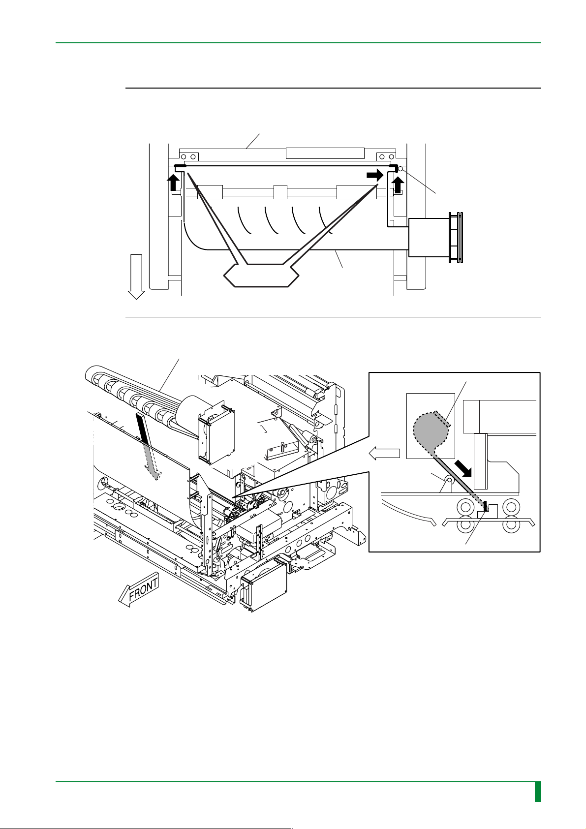
(2) Install the light-collecting guide assembly (for front surface).
◆
INSTRUCTION
◆
When installing the light-collecting guide assembly, properly position it by pressing it
against the mirror assembly and positioning pin.
Mirror assembly
Positioning pin
F
R
O
N
T
CHECK
Light-collecting
guide assembly
FR7H7247.EPS
IN - 33
[Attach] Light-collecting guide assembly
Light-collecting
guide assembly
FRONT
Roller bearing
Positioning pin
FR7H7213.EPS
009-058-00
10.20.2000 FM2732 (2)
CR-IR347
Service Manual
IN - 33
Page 39
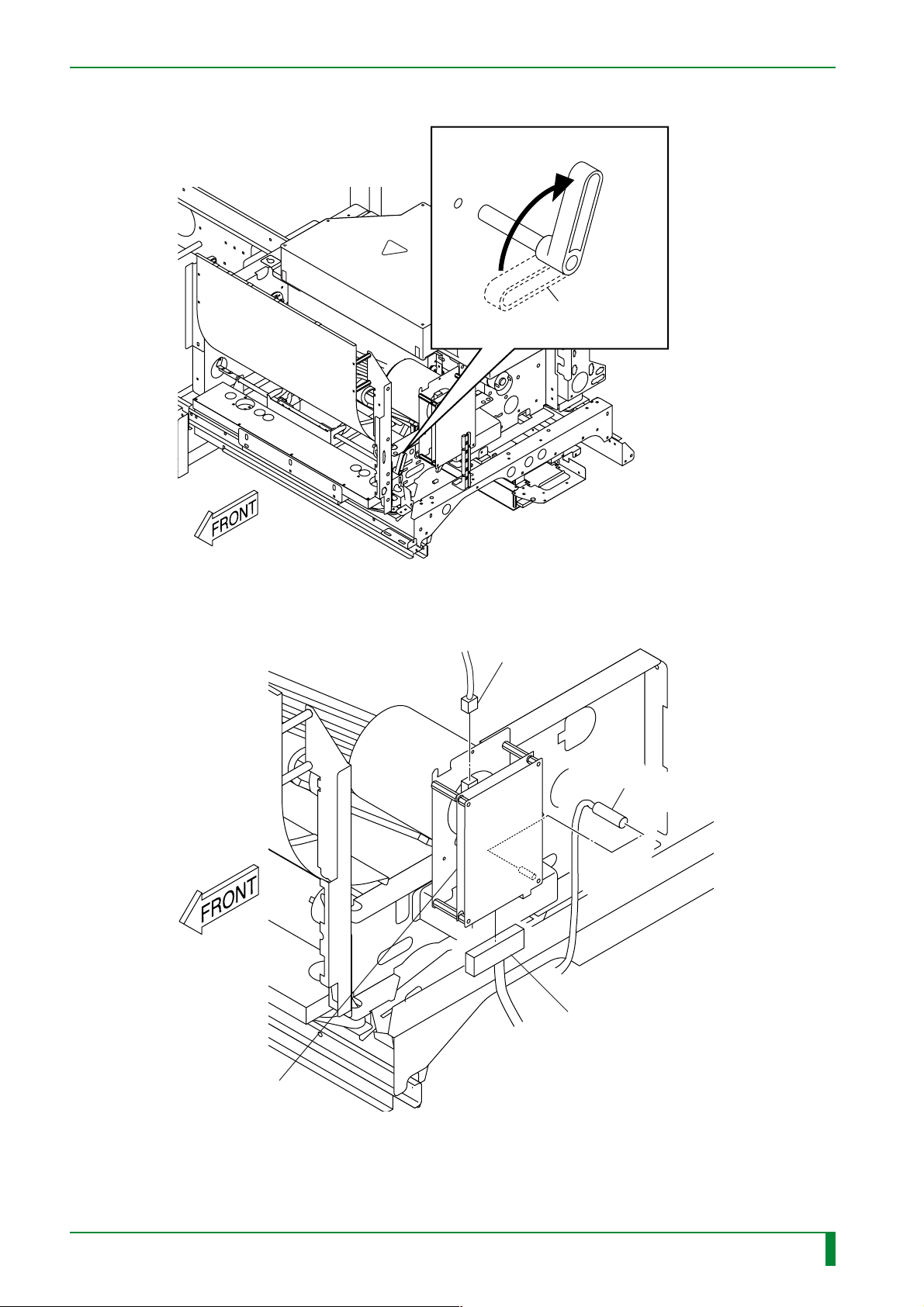
(3) Rotate the lever in the direction of the arrow in the figure below.
[Rotate] Lever
IN - 34
(4) Connect the PMT08D board connectors.
FR7H6137.EPS
[Connect] CN4
[Connect]
CN2
009-058-00
10.20.2000 FM2732 (2)
PMT08D board
CR-IR347
Service Manual
[Connect] CN1
FR7H7209.EPS
IN - 34
Page 40
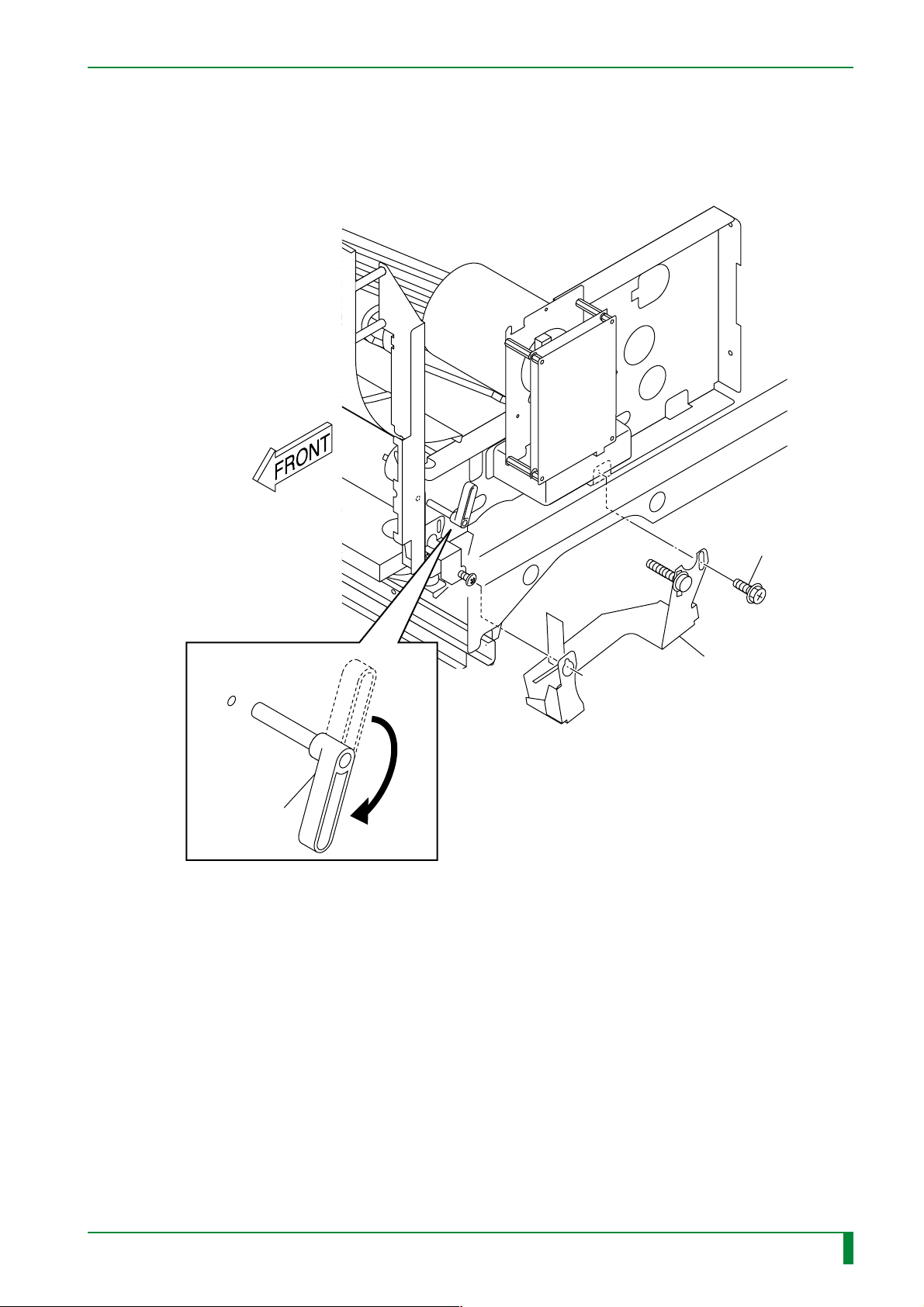
5.2 Light-Collecting Guide Assembly (for the Back)
(1) Remove the bracket.
(2) Rotate the lever clockwise.
IN - 35
(2)
[Rotate] Lever
(1) #1
[Remove]
BR4x8
(1) #2
[Remove] Bracket
FR7H6133.EPS
009-058-00
10.20.2000 FM2732 (2)
CR-IR347
Service Manual
IN - 35
Page 41
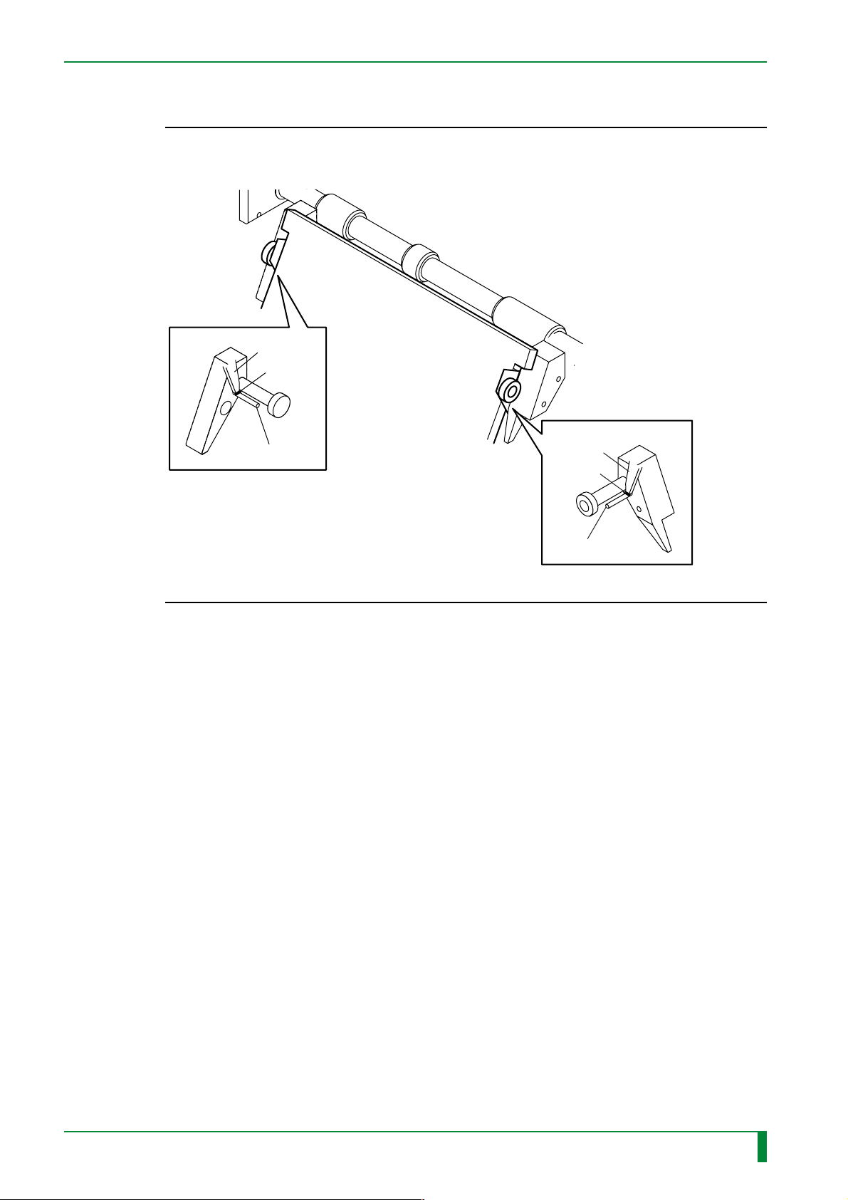
(3) Install the light-collecting guide assembly (for the back).
◆
NOTE
◆
When installing the light-collecting guide assembly, ensure that its claws are positioned
above the guide pins.
IN - 36
Claw
[Attach]
Pin
Light-collecting guide
assembly
Claw
[Attach]
Pin
FR7H7249.EPS
009-058-00
10.20.2000 FM2732 (2)
CR-IR347
Service Manual
IN - 36
Page 42
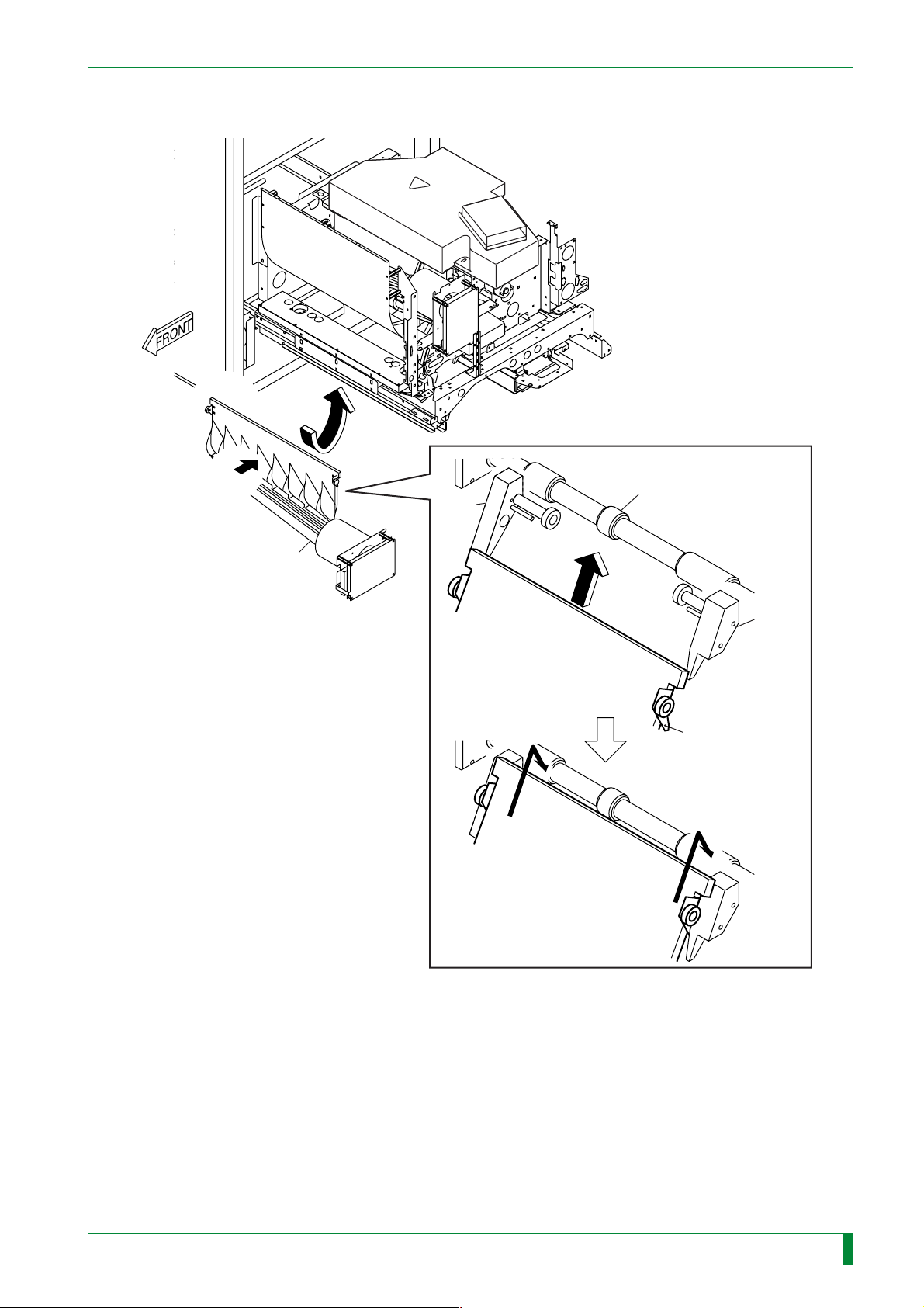
IN - 37
A
[Attach]
Light-collecting guide
assembly
(for back surface)
Guide
Light-collecting guide
assembly
Light-collecting guide
assembly
Rubber roller (driving-side)
Guide
Claw
009-058-00
10.20.2000 FM2732 (2)
CR-IR347
Service Manual
FR7H7248.EPS
IN - 37
Page 43
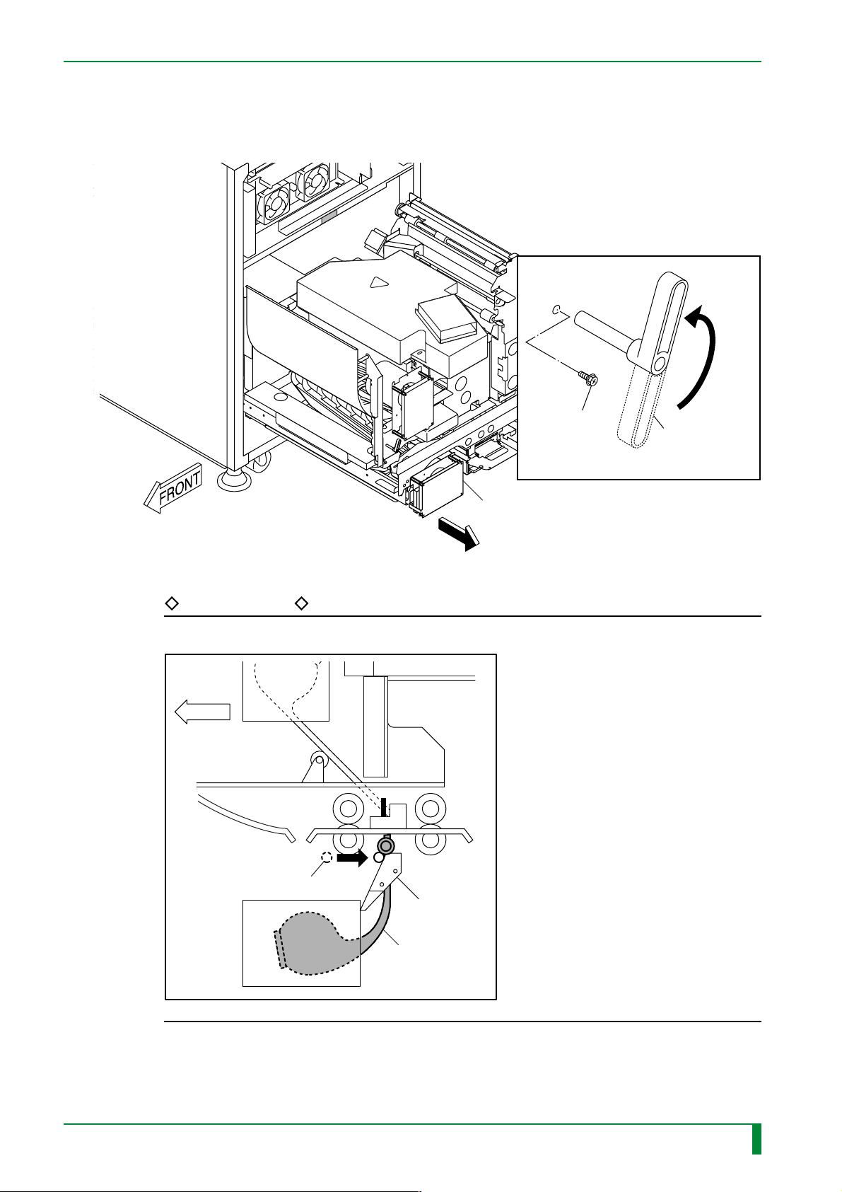
IN - 38
(4) Move the light-collecting guide assembly (for the rear) toward the reference plane.
(5) Rotate the lever in the direction of the arrow in the figure below to secure the light-
collecting guide assembly (for back surface).
(5)#2
[Attach]
BR4x8
(5)#1
[Rotate] Lever
(4)
Light-collecting guide assembly
(for back surface)
FR7H7250.EPS
REFERENCE
Rotating the lever causes the pressure shaft to secure the light-collecting guide.
FRONT
Pressure shaft
Guide
009-058-00
10.20.2000 FM2732 (2)
CR-IR347
Light-collecting
guide assembly
FR7H7236.EPS
Service Manual
IN - 38
Page 44
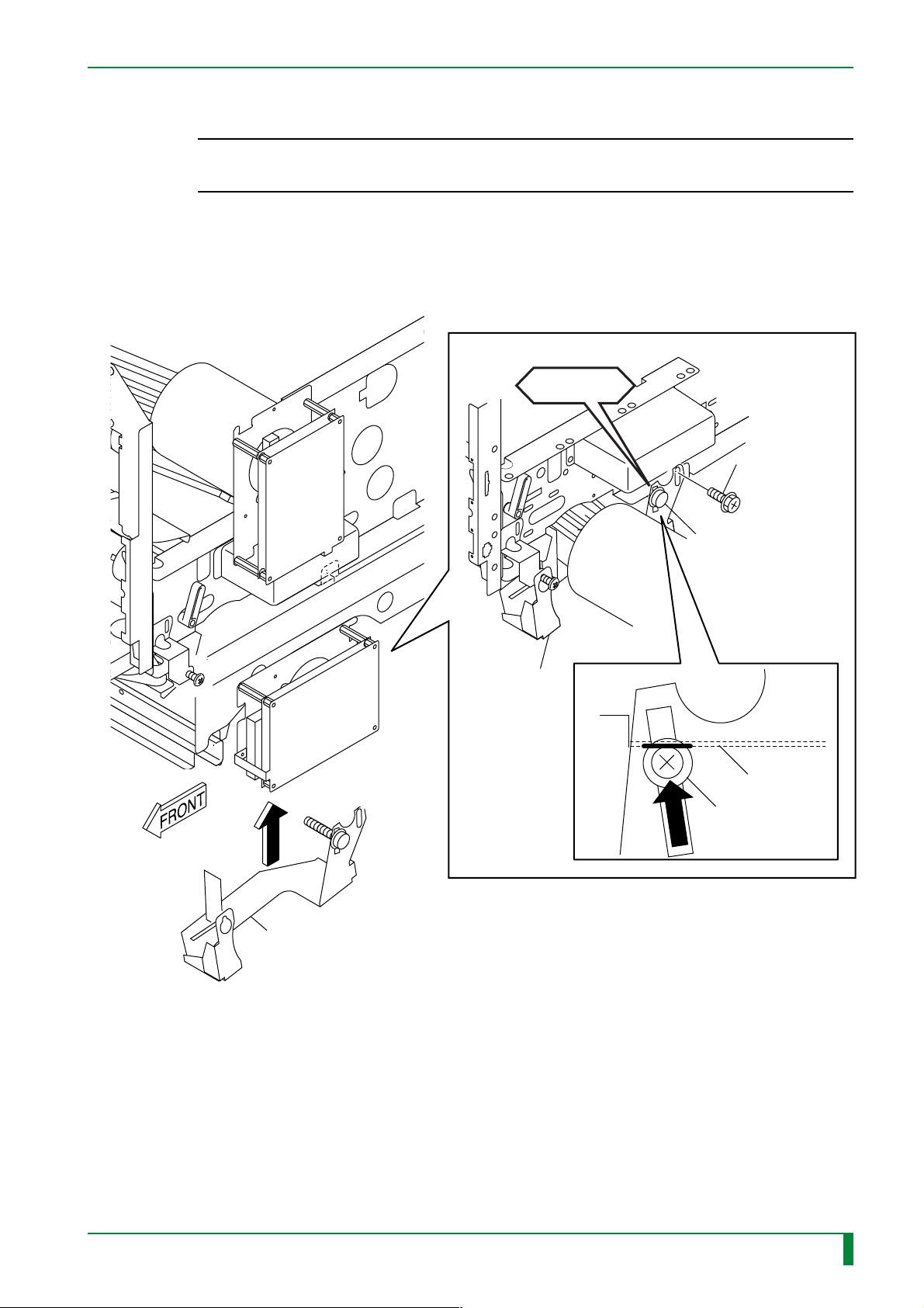
(6) Attach the bracket.
◆
INSTRUCTION
◆
When installing the bracket, secure it while pressing its positioning screw against the
side plate.
CHECK
#2
[Attach] BR4x8
IN - 39
Bracket
#1
[Attach] Positioning pin
Bracket
Side plate
Positioning pin
FR7H7251.EPS
009-058-00
10.20.2000 FM2732 (2)
CR-IR347
Service Manual
IN - 39
Page 45
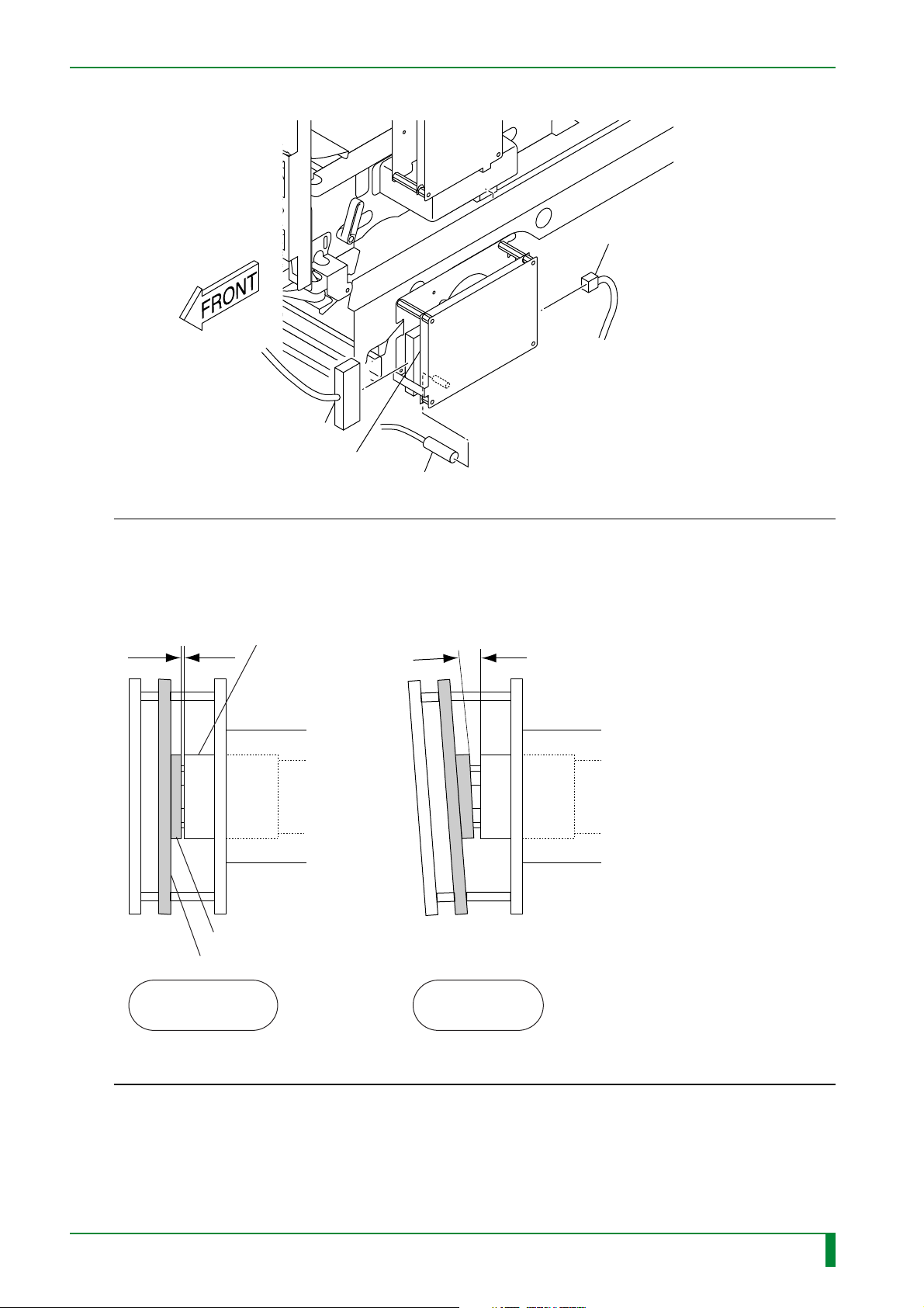
(7) Connect the PMR08C board connectors.
[Connect] CN1
PMR08C board
[Connect] CN2
IN - 40
[Connect]
CN4
FR7H7217.EPS
◆
CHECKS
◆
• Check the mounted position of the light-collecting guide assembly (for front surface).
• Check that the PMT08DPMR08C board socket section is parallel to the light-collecting guide
connector section.
Parallel Not parallel
Connector section
Socket section
PMT08D/PMR08C board
GOOD NG
009-058-00
10.20.2000 FM2732 (2)
CR-IR347
Service Manual
FR7H7033.EPS
IN - 40
Page 46
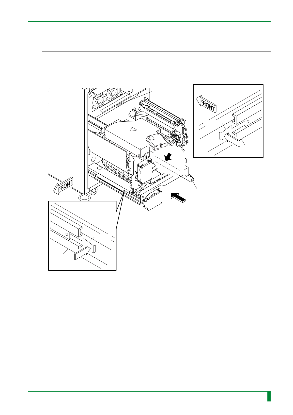
5.3 Pushing In the Scanner Unit
◆
NOTES
• When pushing in the scanner unit, exercise care so that the disconnected connectors and
cables are not caught.
• Push the scanner unit all the way into the machine, while pressing the stoppers of the slide
rails.
◆
IN - 41
HHS label #2
A
DETAIL A
Stopper
PUSH
Slide
rail
Scanner unit
Stopper
Slide rail
PUSH
By reversing the pull-out procedures, push in the scanner unit.
FR7H7232.EPS
009-058-00
10.20.2000 FM2732 (2)
CR-IR347
Service Manual
IN - 41
Page 47
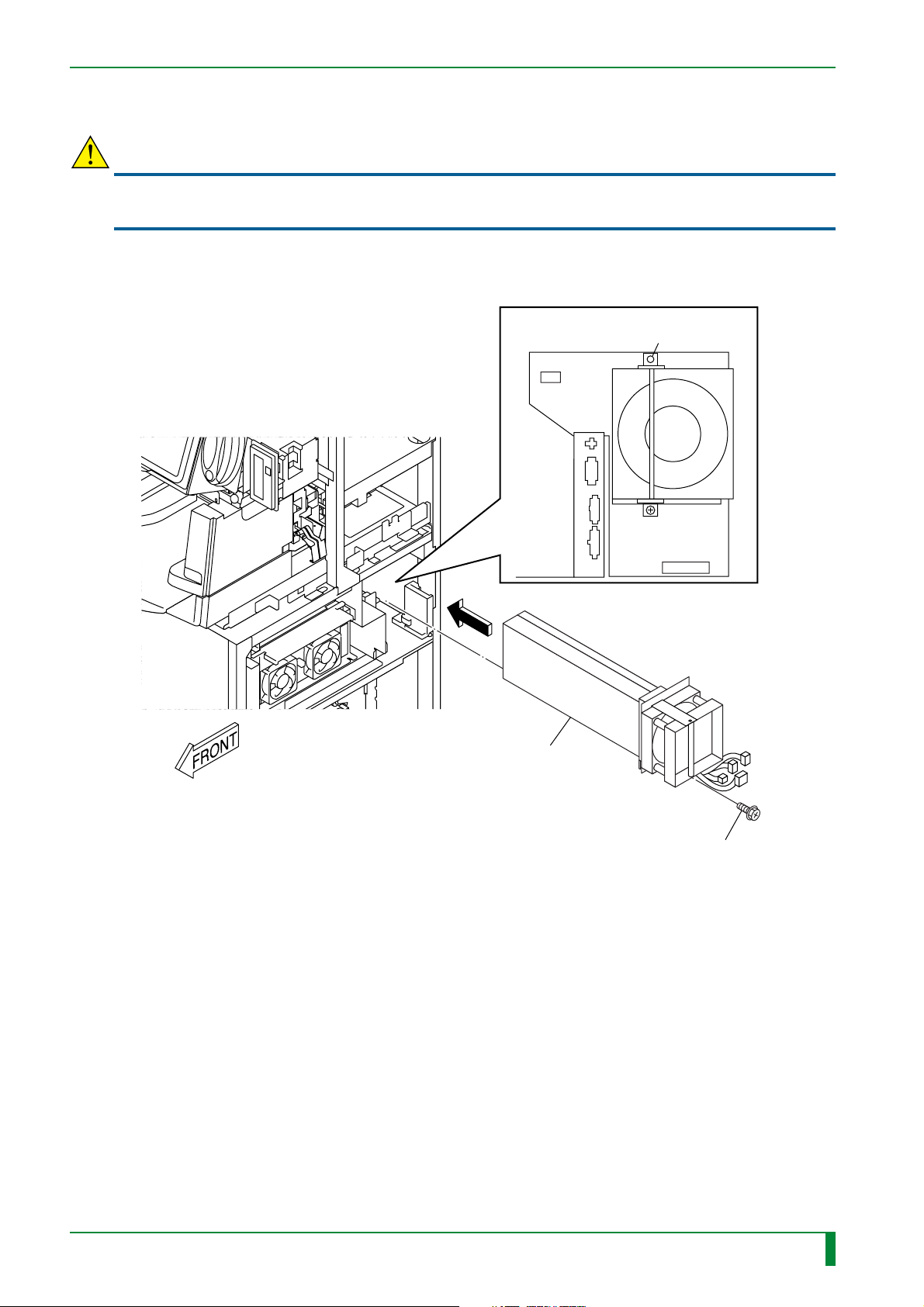
5.4 Erasure Lamp Assembly
CAUTION
The erasure lamp should be handled carefully. If it is hit, the erasure lamp may be broken, so
you may get injured.
Insert the erasure lamp assembly into the erasure conveyor.
Erasure conveyor
#3
[Connect] Connectors
DCOUT5
DCOUT4
Positioning pin
IN - 42
ACOUT1
ACOUT2
#1
[Insert] Erasure lamp assembly
[Attach] BR4x8 (separate packaged item)
#2
FR7H7036.EPS
009-058-00
10.20.2000 FM2732 (2)
CR-IR347
Service Manual
IN - 42
Page 48

BLANK PAGE
IN - 43
009-058-00
10.20.2000 FM2732 (2)
CR-IR347
Service Manual
IN - 43
Page 49
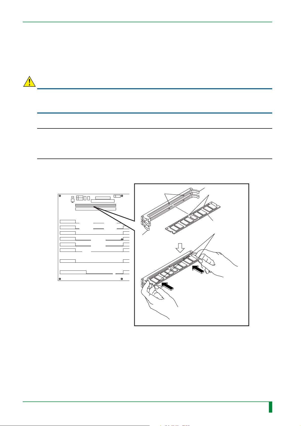
IN - 44
5.5 Memory Boards (Only for Machine with Shipment Control Number of 5079 or Earlier)
Because machines with shipment control numbers of 5080 or later have the memory board
(DIM08A board) mounted by factory default, the board need not be mounted during
installation.
CAUTION
When installing the memory board, be sure to wear an antistatic wristband to ground your body.
If your body is not grounded, static electricity built on your body may cause damage to
electronic parts on the board.
◆
NOTE
When installing the memory board, pay attention to the following points.
• Do not touch the connector portion of the memory board, but grasp both ends of the board.
• Open the tabs of CN17/18, align the notches of the board to the ribs in the CN17/18 slot, and
insert the memory board straight into the slot, while holding both ends of the board.
◆
(1) Install the memory module (MMB90A board) into the connector slot (CN18) of the
MTH08C board.
MTH08C board
Rib
CN18
CN17
Tab
Tab
Notch
MMB90A board
Push both ends
of the module.
009-058-03
08.30.2002 FM3476
CR-IR347
Service Manual
FR7H7220.EPS
IN - 44
Page 50
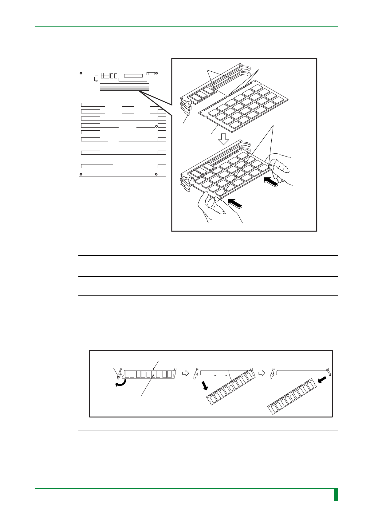
IN - 45
(2) Install the memory module (MMA90A board) into the connector slot (CN17) of the
MTH08C board.
MTH08C board
CN18
CN17
Rib
Tab
MMA90A board
Notch
Push both ends
of the module.
FR7H7219.EPS
◆
CHECK
◆
Make sure that the tabs of CN17 and CN18 have been closed and memory boards
have been securely locked into place.
◆
NOTE
◆
To remove the memory module, take the following procedures. If the procedures are
not observed, the connector tab(s) may be damaged.
(1) Push out the left tab of the connector.
(2) Press out the left end of the memory module at an angle of 30-40 degrees.
(3) Remove the memory module.
Top view
(1) (2) (3)
Left tab
MMA90A board/
MMB90A board
Connector
30 –40
FR7H7231.EPS
009-058-00
10.20.2000 FM2732 (2)
CR-IR347
Service Manual
IN - 45
Page 51
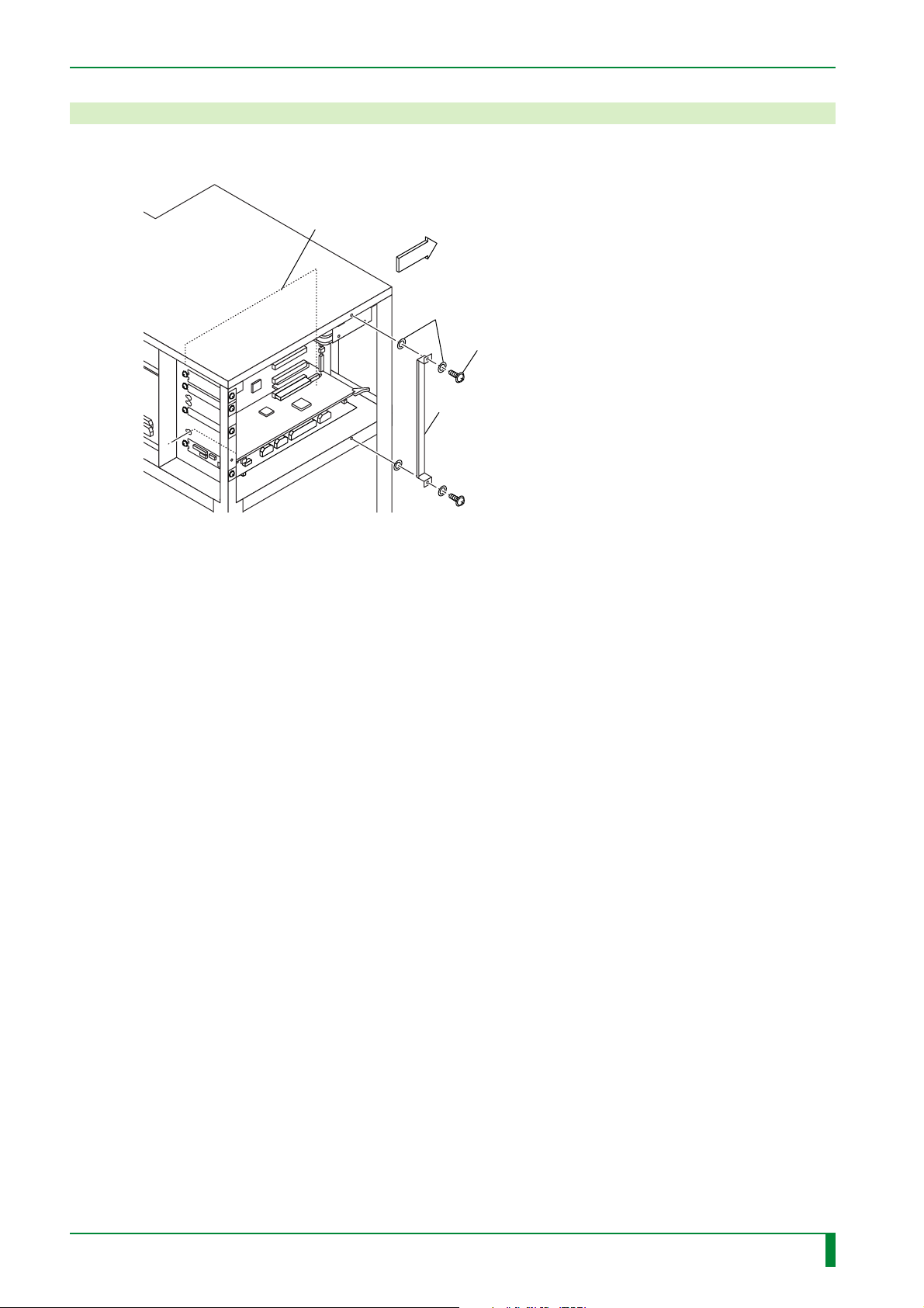
6. Removing the Board Retaining Plate
Remove the board retaining plate.
MTH08C board
FRONT
Plastic washer
[Remove]
BR3x6 (x2)
Board retaining plate
IN - 46
FR7H7043.EPS
009-058-00
10.20.2000 FM2732 (2)
CR-IR347
Service Manual
IN - 46
Page 52
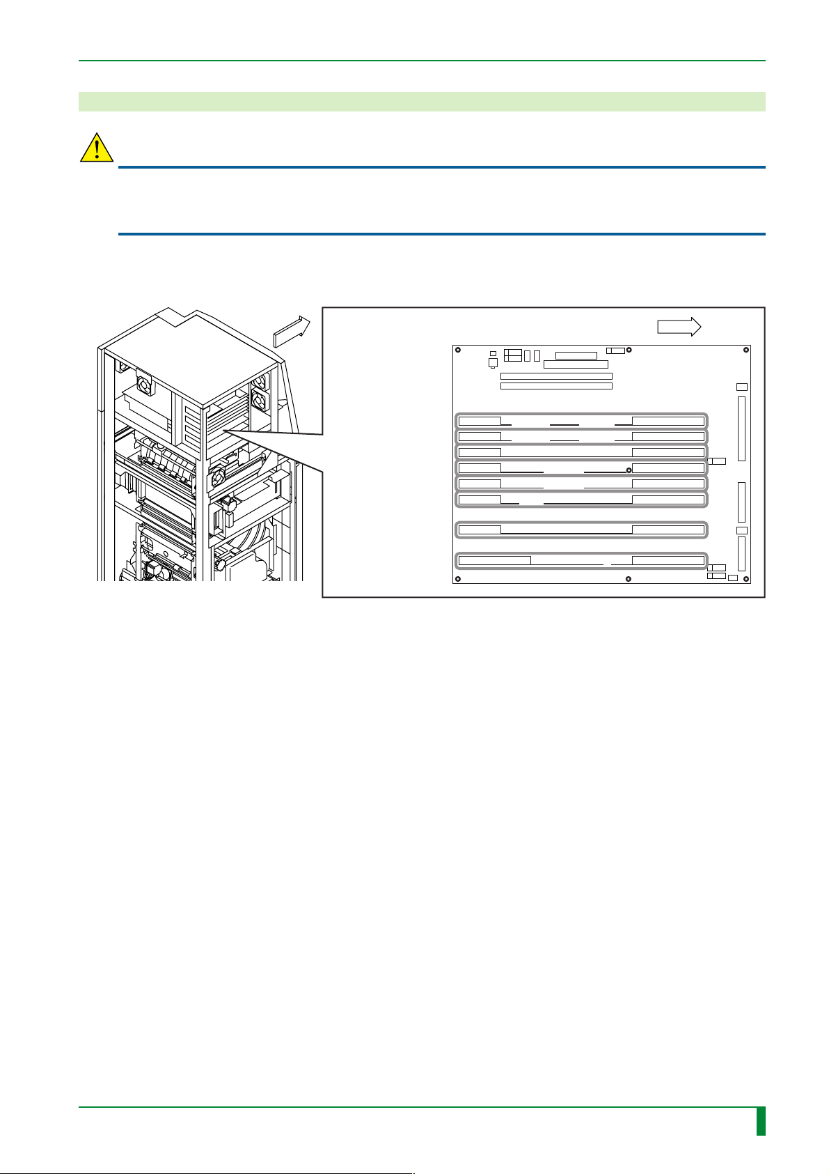
7. Setting the Boards
CAUTION
When servicing any printed circuit board, be sure to wear an antistatic wristband to ground your
body. If your body is not grounded, static electricity built on your body may cause damage to
electronic parts on the board.
■ Boards in the Controller
IN - 47
FRONT
CPU90F board
HCP08A board
IMG08H board (PEM)
IMG08H board (MFP)
IMG08M board
BSP08A board
IMG07B board
CPU90E board
MTH08C board
FRONT
FR7H7226.EPS
009-058-00
10.20.2000 FM2732 (2)
CR-IR347
Service Manual
IN - 47
Page 53
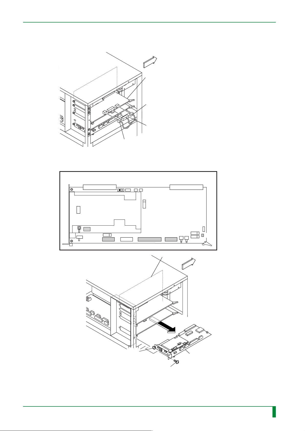
■ CPU90E Board
(1) Disconnect the connectors of the BSP08A board.
(2) Remove the CPU90E board.
IN - 48
FRONT
BSP08A board
[Disconnect] CN4
[Disconnect] CN3
[Disconnect] CN5
FR7H7119.EPS
#1 [Disconnect] Connectors
CN19
CN7
CN11
CN8
CPU90E board
CN18
CN6
MTH08C board
FRONT
009-058-00
10.20.2000 FM2732 (2)
#2
[Loosen] T4x8
CR-IR347
#3
[Remove] T4x8
Service Manual
CPU90E board
FR7H7045.EPS
IN - 48
Page 54
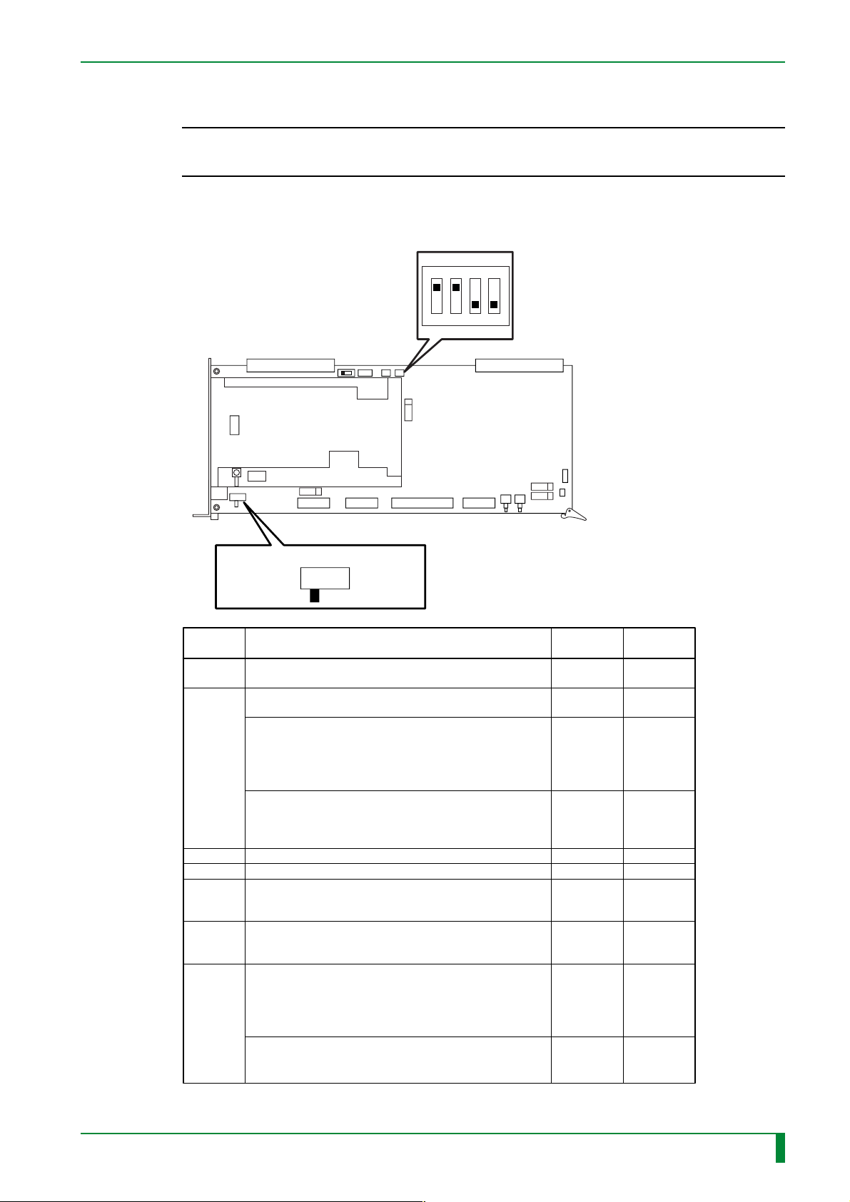
(3) Place bits 1 and 2 (battery backup switch) of S2 in the ON position.
◆
NOTE
◆
If bits 1 and 2 of S2 remain in the OFF position, the memory backup cannot be done,
so that settings cannot be retained.
(4) Place S5 in the STRAIGHT position.
S2
OFF position
4321
ON position
CN2 CN1
IN - 49
S5
STRAIGHT position
Setting Function
Generic setup switch.
S1
The setup value is loaded and used by the software.
1) S2-1 and S2-2 (Both should be the same setting.)
Sets to turn ON/OFF the battery backup function.
2) S2-3
Sets to turn ON/OFF the NMI signal issuance function
S2
S3
S4
S5
S6
S7
of the MTH08C.
It should be turned OFF because the current MTH08C
does not support the NMI signal issuance function.
3) S2-4
Sets to turn ON/OFF the write into the boot ROM.
This function is effective only when the Flash EEPROM
is used as the Boot ROM; thus, it is not used at present.
Issues manual reset.
Issues manual NMI.
Switches connection type (CROSS/STRAIGHT) of the
ID-Network line.
Switches the signal level (RS-422/RS-232C) of the IDT
communication line.
Sets to turn ON/OFF the power remote control function
with the IDT.
1) S7-1 and S7-2 (Both should be the same setting.)
Turns ON/OFF the power remote control function, from
IR to IDT.
2) S7-3 and S7-4 (Both should be the same setting.)
Turns ON/OFF the power remote control function, from
IDT to IR.
CROSS position
FR7H7047.EPS
Factory
default
All bits OFF
OFF ON
OFF OFF
OFF OFF
––
––
Set in the
STRAIGHT
position.
Set in the
RS-422
position.
ON ON
ON ON
Installation
setting
All bits OFF
Set in the
STRAIGHT
position.
Set in the
RS-422
position.
TR7H7007.EPS
(5) By reversing the procedures of step (1) and (2), reinstall the CPU90E board.
009-058-00
10.20.2000 FM2732 (2)
CR-IR347
Service Manual
IN - 49
Page 55
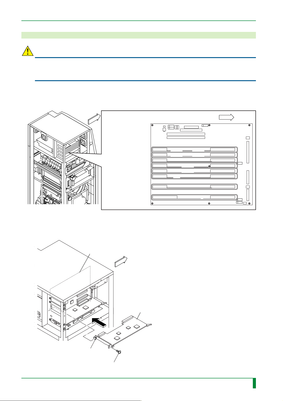
8. Installing the Boards
CAUTION
When servicing any printed circuit board, be sure to wear an anti-static wristband to ensure
proper grounding. If not, static electricity built on the human body may cause damage to electric
parts mounted on the board.
■ Boards Locations in the Controller
IN - 50
FRONT
CPU90F/LAN90B board
HCP08A board
IMG08H board (PEM)
IMG08H board (MFP)
IMG08M board
BSP08A board
IMG07B board
CPU90E board
■ Example of Installing the Optional Board
MTH08C/D board
MTH08C/D board
FRONT
FR7H7226.EPS
009-058-03
08.30.2002 FM3476
[Attach] T4x8
[Tighten] T4x8
FRONT
CR-IR347
Optional board
FR7H7211.EPS
Service Manual
IN - 50
Page 56
■ Installing the optional boards
Install the following optional boards:
• IMG08M board (LP interface board)
• IMG08H board (high-speed multi-frequency processing board: MFP)
• IMG08H board (high-speed breast pattern processing board: PEM)
• HCP08A board (compression/decompression process board for network connection
use)
• CPU90F/LAN90B board (network interface board for network connection use)
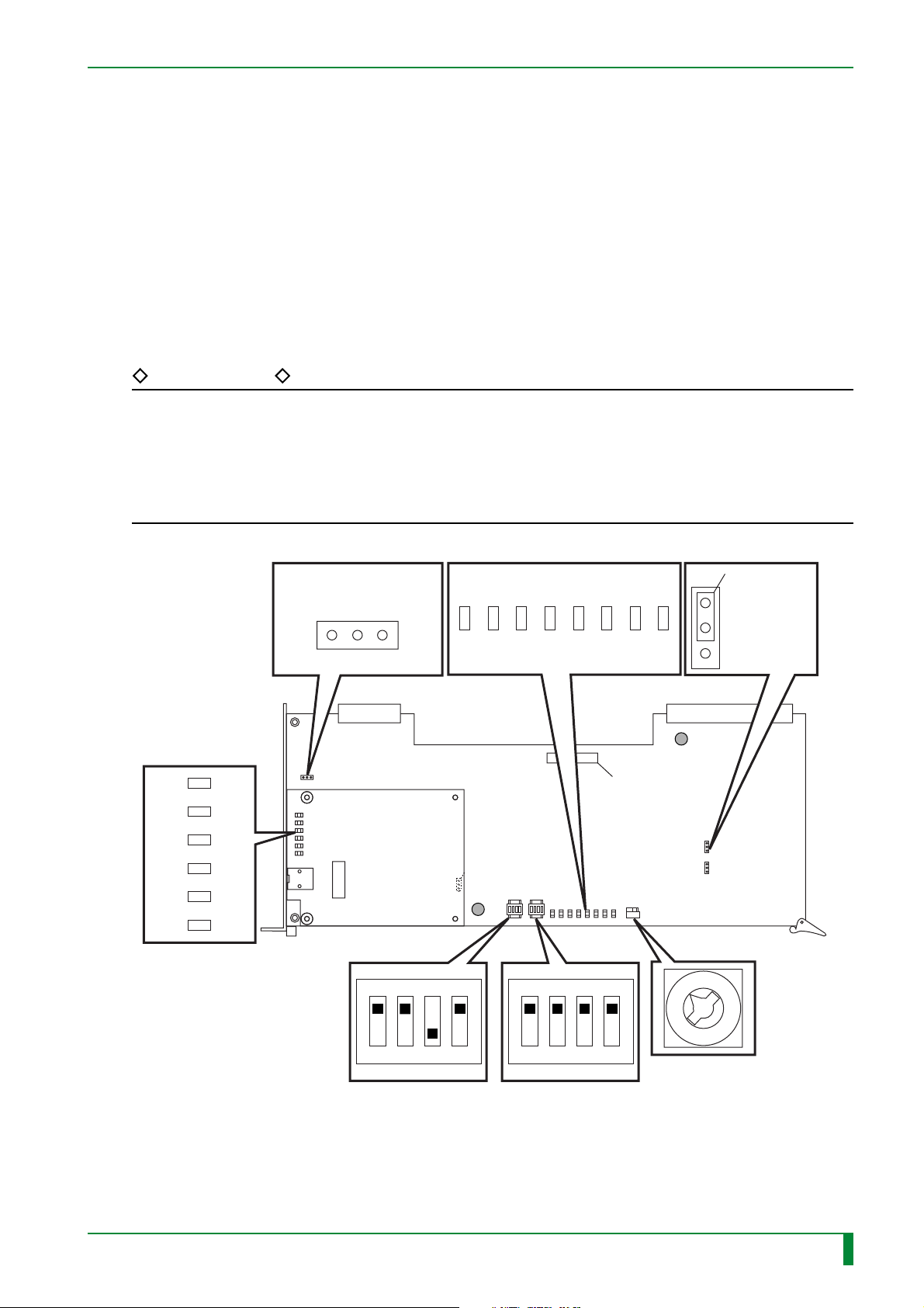
■ Setting the CPU90F board
REFERENCE
The following jumper and switch settings are employed by default.
CNSIO : Jumpers are removed (open).
T1 and T2 : Pins 2 and 3 are shorted.
DIS1 : Switches 1, 3, and 4 are OFF. Switch 2 is ON.
DIS2 : All switches are OFF.
SW1 : “6”.
IN - 51
LED
LED6
LED5
LED4
LED3
LED2
LED1
COL
DUP
LINK
100M
RX
TX
CNSI0
LED
No short pin
(OPEN)
321
CN2
ETH90F board
DIS1 DIS2
OFF position
LED7
LED5
LED6
F2
LED3
LED4
OFF position
LED1
LED2
BOOT ROM
LED0
T1,2
Short pin
3
2
1
CN1
F1
SW1
009-058-03
08.30.2002 FM3476
ON position
CR-IR347
432614321
ON position
Service Manual
Set to "6".
FR7H7254.EPS
IN - 51
Page 57
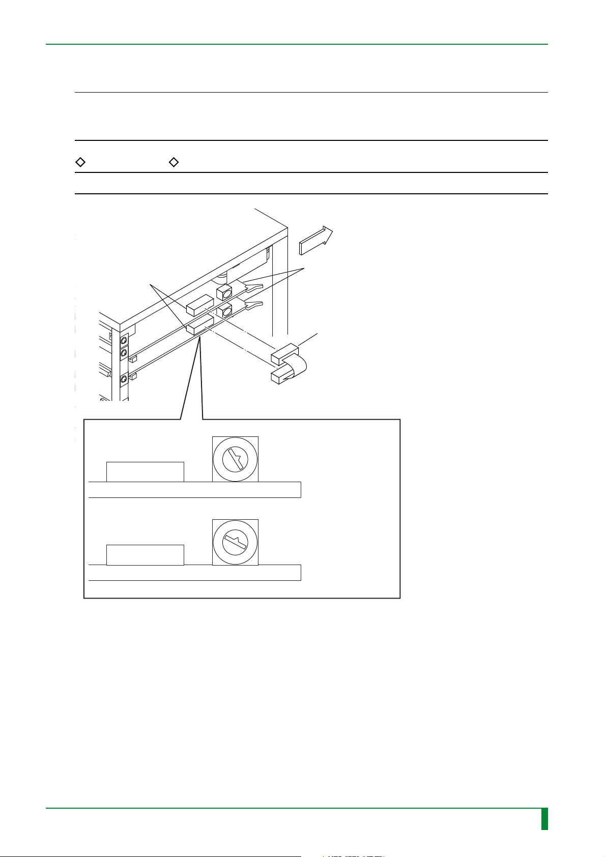
■ Setting up the IMG08H board
◆
NOTE
◆
Connect the high-speed multi-frequency processing board (MFP) and high-speed mammographic
pattern processing board (PEM) with a cable. If they are not connected together, no 20pix/mm
image will be outputted.
REFERENCE
S1 is set to “2” by factory default.
FRONT
IMG08H board
CN3
IN - 51.1
CN3
CN3
S1
S1
[Connect]
Connection cable
3
IMG08H board
(high-speed
mammographic
pattern processing
2
board: PEM)
IMG08H board
(high-speed multifrequency processing
board: MFP)
FR7H7243.EPS
009-058-02
009-058-02
08.30.2001 FM3142 (1)
08.30.2001 FM3142
CR-IR347
Service Manual
IN - 51.1
Page 58
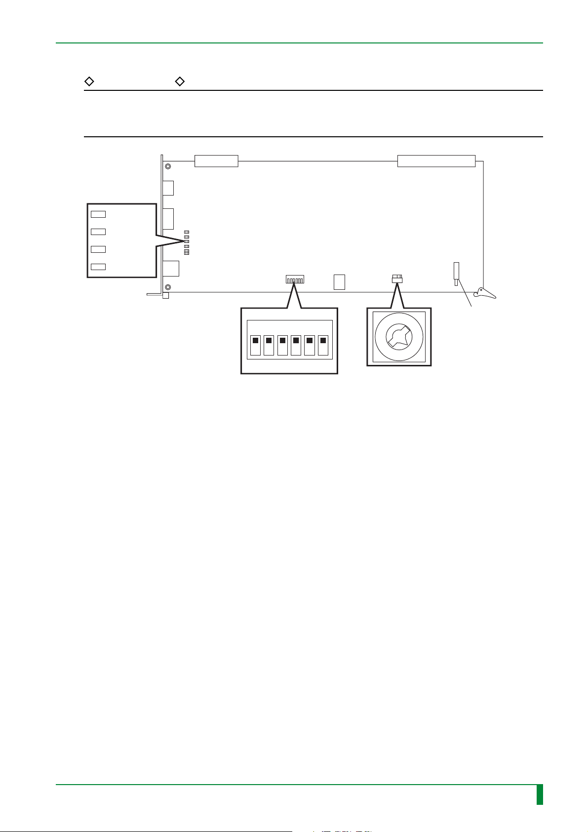
■ Setting the LAN90B board
REFERENCE
The following jumper and switch settings are employed by default.
S2 : All switches are OFF.
S3 : “6”.
CN2
D10 100
D13 TX
IN - 51.2
S3
CN1
D12 RX
D11 FDP02
CN7
S2
OFF position
ON position
S1
CN6
S3
Switch for resetting
436521
the LAN90B board
6
Set to “6”.
FR7H1937.EPS
009-058-03
009-058-02
08.30.2002 FM3476
08.30.2001 FM3142
CR-IR347
Service Manual
IN - 51.2
Page 59

BLANK PAGE
IN - 51.3
009-058-02
08.30.2001 FM3142
CR-IR347
Service Manual
IN - 51.3
Page 60

BLANK PAGE
IN - 51.4
009-058-02
08.30.2001 FM3142
CR-IR347
Service Manual
IN - 51.4
Page 61
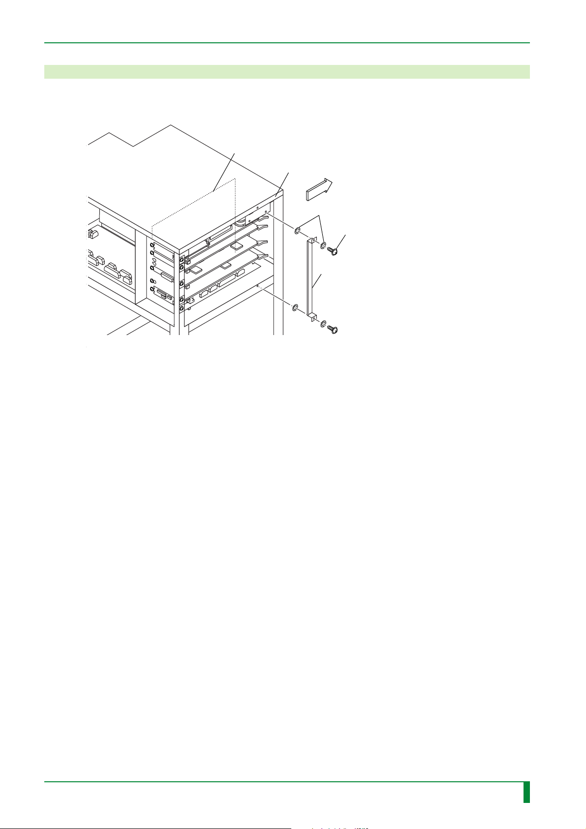
9. Installing the Board Retaining Plate
Install the board retaining plate.
MTH08C board
Frame
FRONT
Plastic washer
[Attach] B3x6 (x2)
Board retaining plate
IN - 52
FR7H7059.EPS
009-058-01
009-058-02
05.15.2001 FM3052
08.30.2001 FM3142
CR-IR347
Service Manual
IN - 52
Page 62
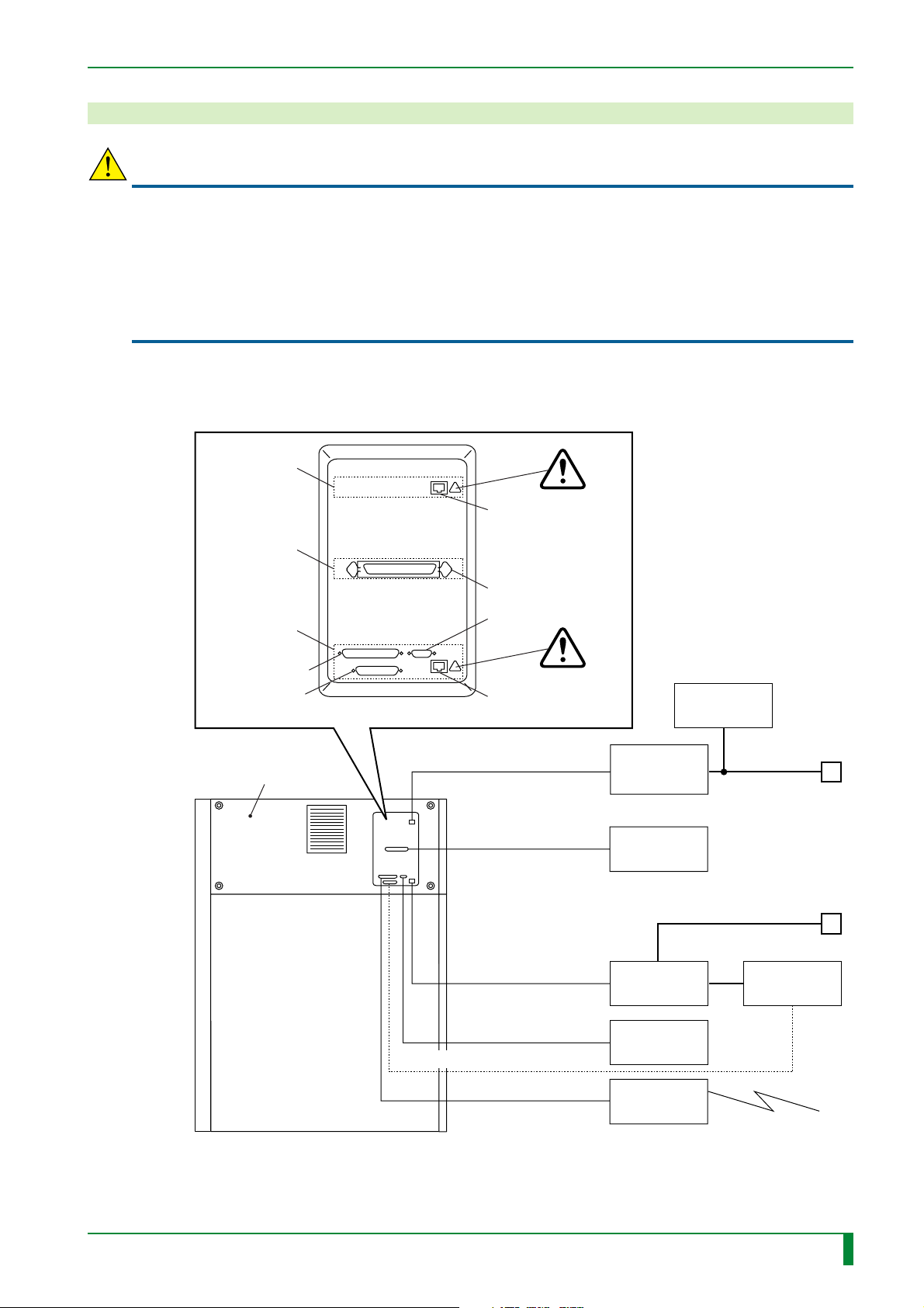
10. Connecting the Interface Cables
CAUTIONS
• A telephone cable should not be plugged into the connector marked by “ATTENTION”. Only
10Base-T or 100Base-T cables (IEC950/UL1950-listed) are suited for connection to this
machine.
• For the network cable connected to the CPU90F board, a shielded type (STP) should be
used.
• For the network cable connected to the LAN90B board, a shield type (STP) or an unshielded
type (UTP) should be used.
(1) Install the upper rear cover.
(2) Referring to the illustration below, connect the interface cables.
CPU90F/
LAN90B
IMG08M board
board
For hub (100Base-T
or 10Base-T)
IN - 53
CPU90E board
For modem
For remote
switch
Upper rear
cover
For LP
For monitor
For hub
(for IDT, 10Base-T)
100Base-T or 10Base-T
I/F cable
LP I/F cable
10Base-T I/F cable
Monitor I/F cable
Remote switch I/F cable
CR Console
(CR-IR348CL)
HUB
(100BASE-T
or 10BASE-T)
LP
HUB
(10BASE-T)
VGA monitor
Network
Network
ID-T741
009-058-03
08.30.2002 FM3476
CR-IR347
Modem I/F cable
Service Manual
Modem
FR7H7062.EPS
IN - 53
Page 63
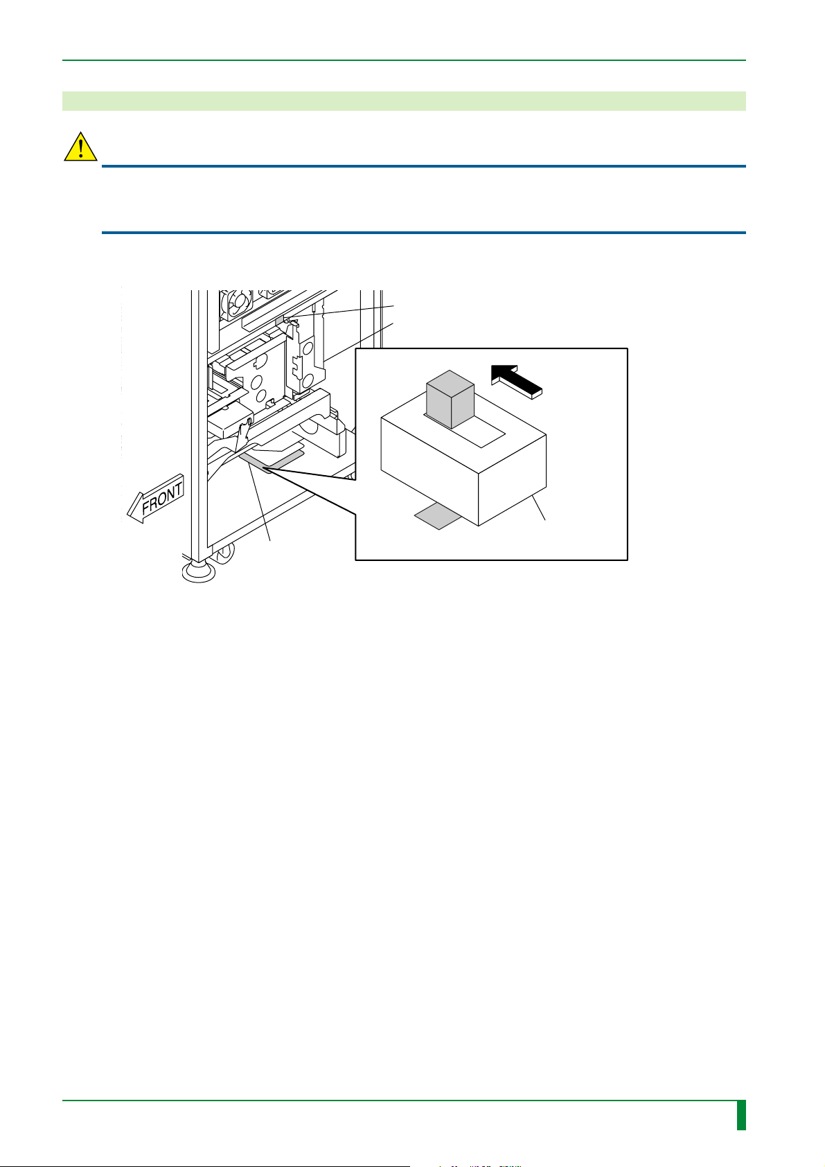
11. Turning OFF the High-Voltage Switch
CAUTION
Before powering ON the machine with the covers removed, be sure to turn OFF the highvoltage switch. If the machine is powered ON with any of the covers removed, the
photomultiplier will be damaged.
Turn OFF the high-voltage switch (S1) of the SCN08D board.
HHS label #2
Scanner unit
OFF position
IN - 54
SCN08D
board
S1
HV
ON
High-voltage
switch
FR7H7063.EPS
009-058-01
05.15.2001 FM3052
CR-IR347
Service Manual
IN - 54
Page 64
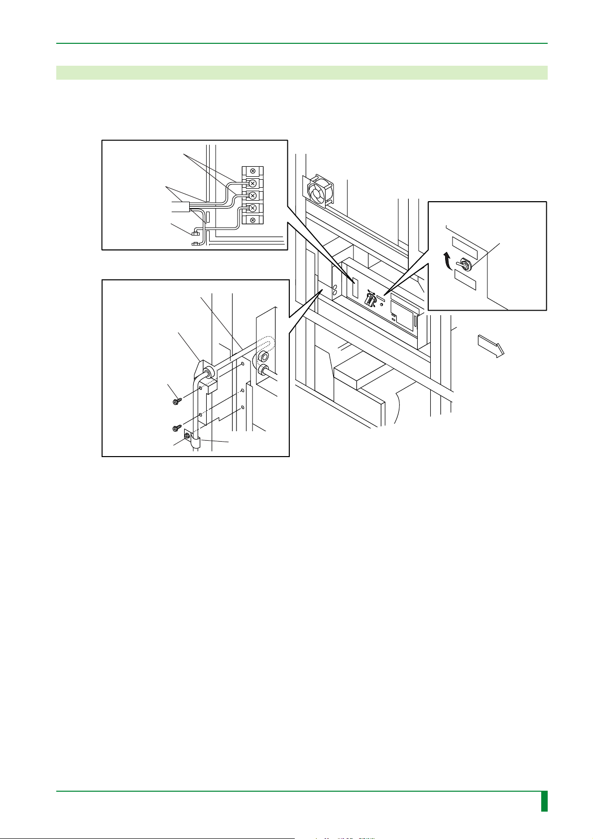
12. Connecting the Power Cable
(1) Place the REMOTE/LOCAL switch in the REMOTE position.
(2) Connect the power cable to TB1.
IN - 55
(2)
[Connect]
Power cable
Hole
Screw located
behind
(2)
#2 [Attach]
BR4x8 (x2)
Power cable
Bracket
#3 [Attach]
BR4x8
#1
FG
TB1
L
N
G
(1)
E
Remote
REMOTE/
LOCAL
switch
Local
ON
RESET SW
OFF
Remote
Local
FRONT
NK clamp
FR7H7064.EPS
FR7H7064.EPS
009-058-01
05.15.2001 FM3052
CR-IR347
Service Manual
IN - 55
Page 65
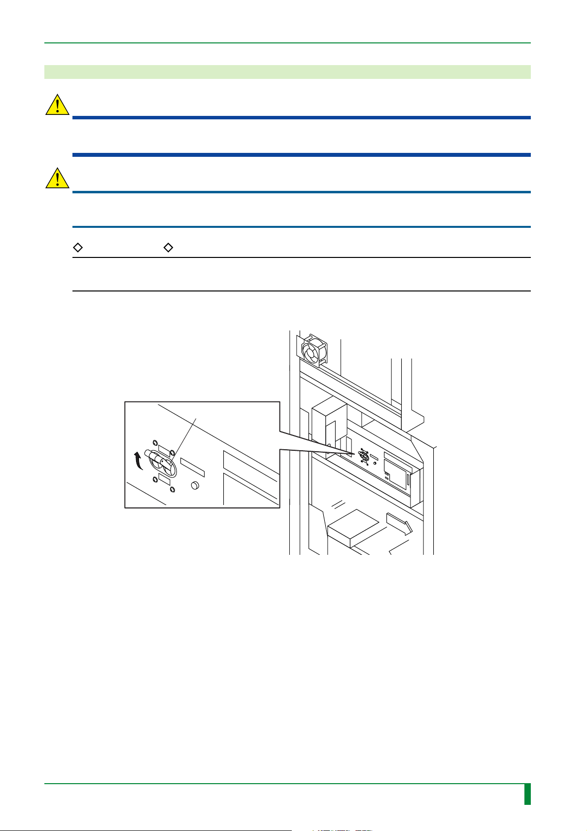
13. Checking the Resistance Values
WARNING
Before measuring the resistance value, unplug the power plug or power supply terminal from
the outlet or power distribution switchboard.
CAUTION
If anything abnormal is found with the result of power-supply short checks, refer to the
“Troubleshooting Volume” to take remedial action, and then proceed to the next step.
REFERENCE
With this machine, it is not necessary to change the line voltage setting according to differing
power supplies (100 V or 200-240 V).
(1) Turn ON the circuit breaker.
IN - 56
ON
OFF
Circuit breaker
RESET SW
Remote
Local
O
N
R
E
S
E
T
S
W
O
F
F
R
e
m
o
t
e
L
o
c
a
l
FRONT
FR7H7065.EPS
009-058-01
05.15.2001 FM3052
CR-IR347
Service Manual
IN - 56
Page 66
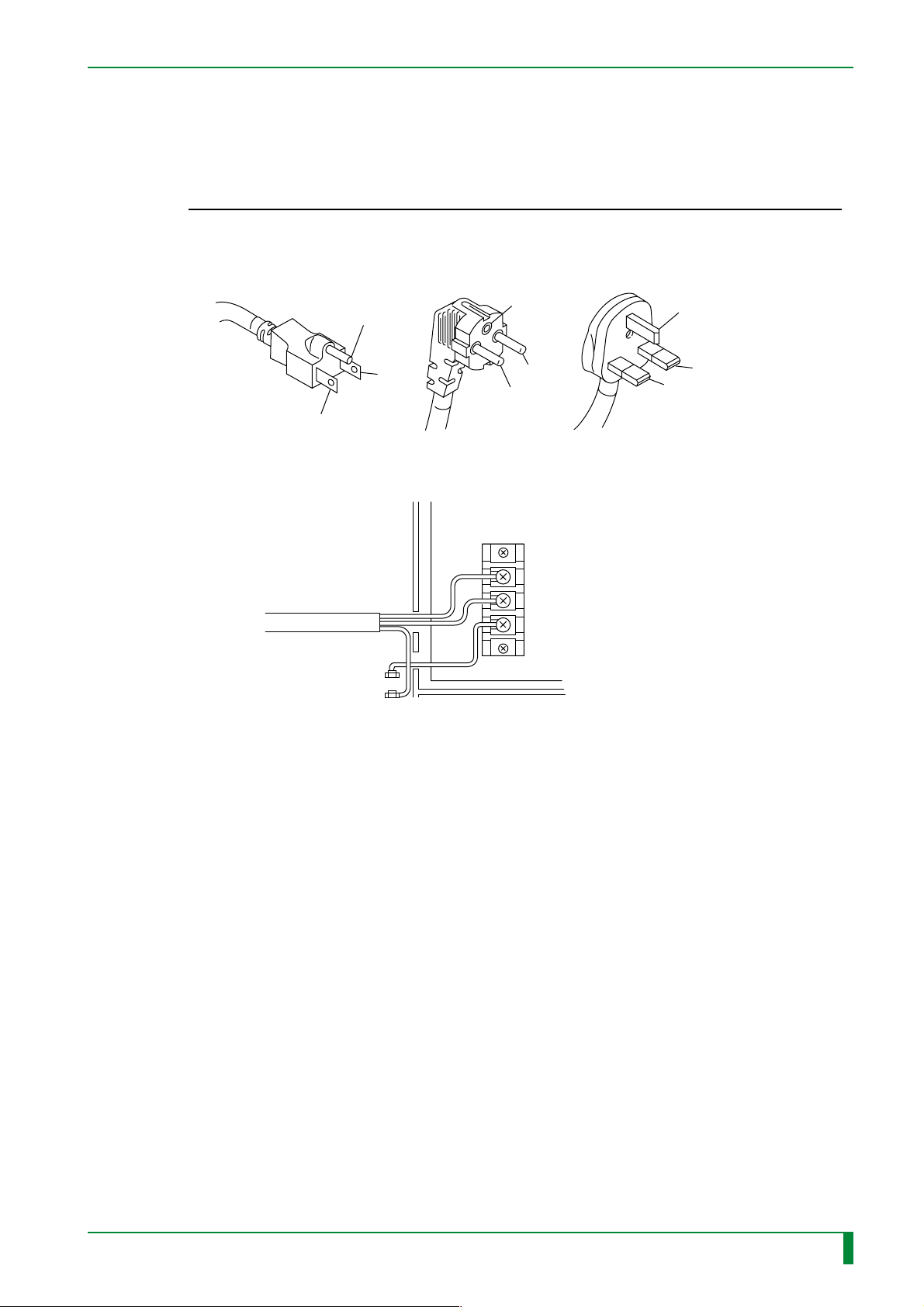
(2) Measure the resistance value.
If the specified value shown in the table below is not met, undo the power supply
hookup and implement it again.
Terminal L–NL–E (FG) N–E (FG) E (FG)–E
Resistance value 180 K–230 KΩ ∞ ∞ 0.2 Ω or less
<For use in Japan and the U.S.> <For use in Europe> <For use in the U.K.>
IN - 57
L→L
N→N
E→FG
E
E
E
L
N
L
N
L
N
L→LINE
N→NEUT
E→FG
L→LINE
N→NEUT
E→FG
TB1
L
N
G
E
FG
FR7H7066.EPS
009-058-02
009-058-01
08.30.2001 FM3142
05.15.2001 FM3052
CR-IR347
Service Manual
IN - 57
Page 67
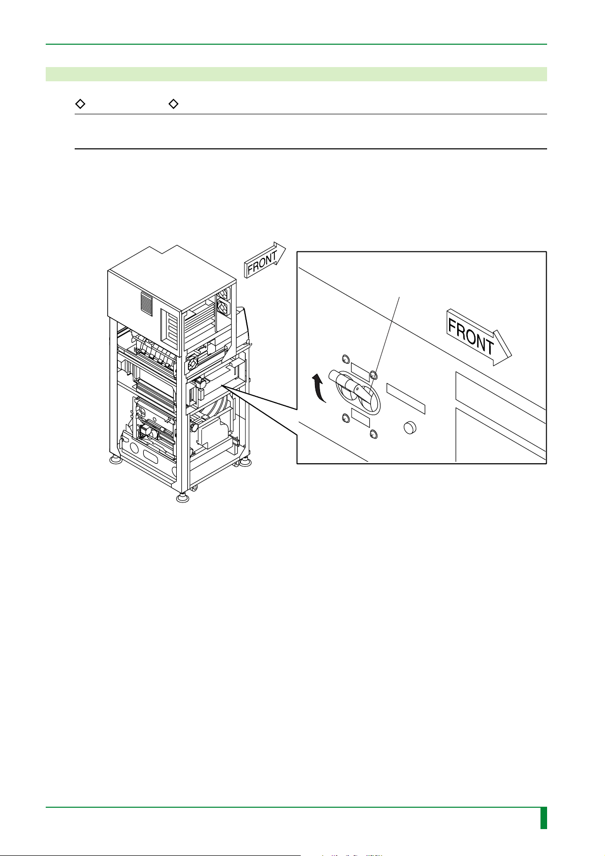
14. Powering ON
REFERENCE
If HV OFF error or IDT/LP connection line error occurs during the initialization sequence, touch
the Confirm button.
(1) Turn OFF the circuit breaker.
(2) Plug the power plug to the outlet.
(3) Turn ON the circuit breaker.
[Turn-ON] Circuit breaker
IN - 58
ON
OFF
RESET SW
FR7H7074.EPS
009-058-02
009-058-01
08.30.2001 FM3142
05.15.2001 FM3052
CR-IR347
Service Manual
IN - 58
Page 68
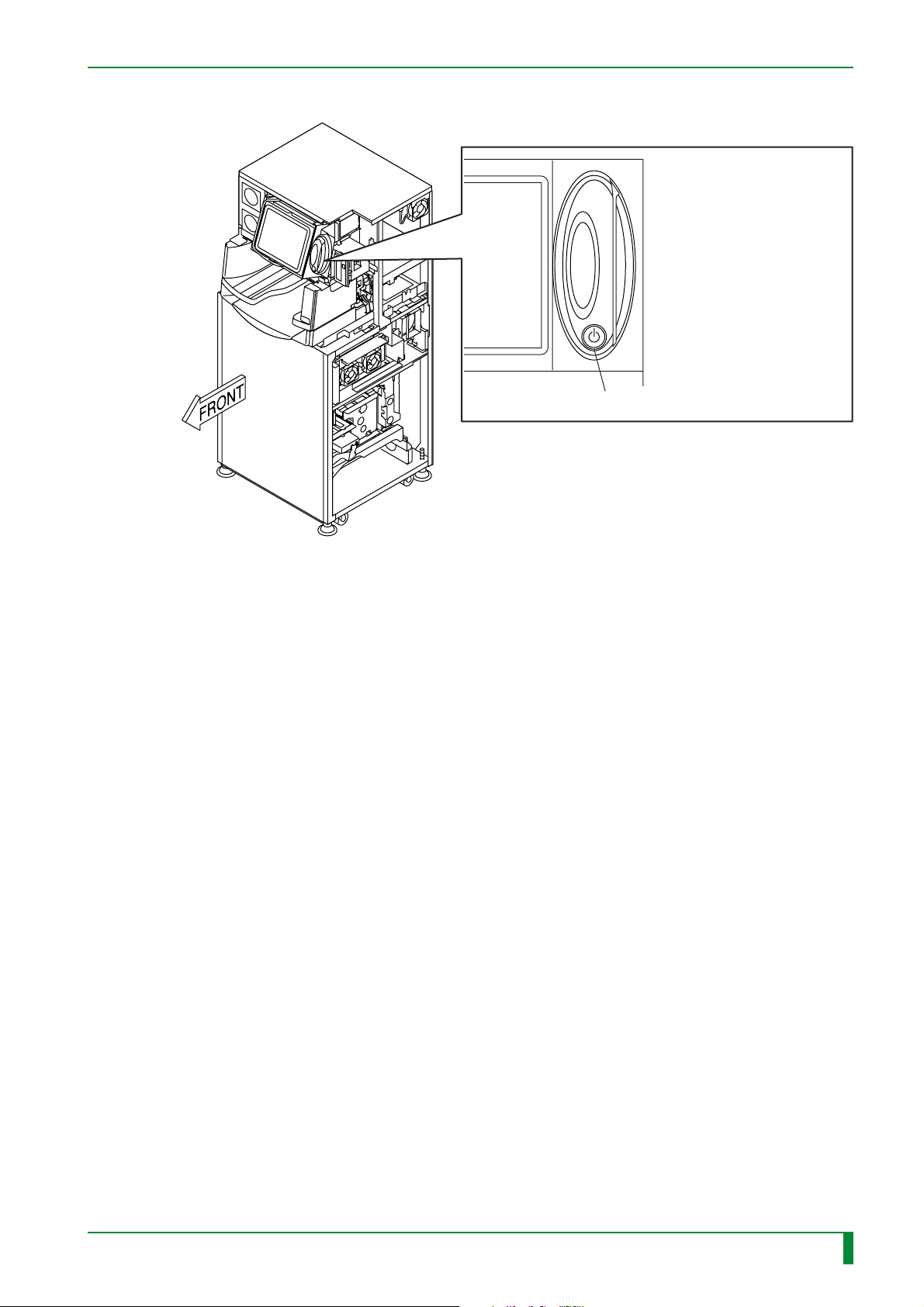
(4) Turn ON the system power switch.
IN - 59
[Turn-ON] System power switch
FR7H7230.EPS
009-058-02
009-058-01
08.30.2001 FM3142
05.15.2001 FM3052
CR-IR347
Service Manual
IN - 59
Page 69
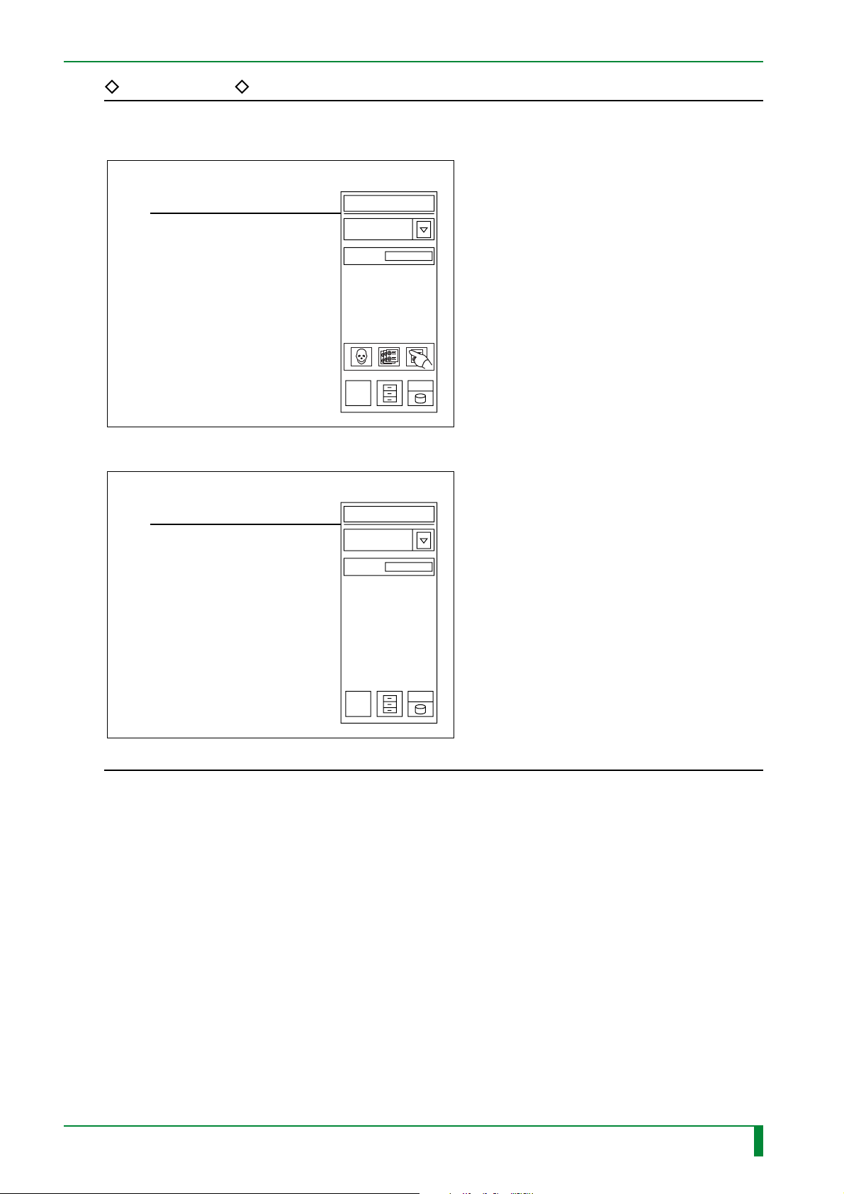
REFERENCE
The screen after normal startup of the machine is as shown below.
Routine screen (CSL specification)
Read
0
IN - 60
Routine screen (IDT specification)
Read
0
FR7H7075.EPS
009-058-01
05.15.2001 FM3052
CR-IR347
Service Manual
IN - 60
Page 70
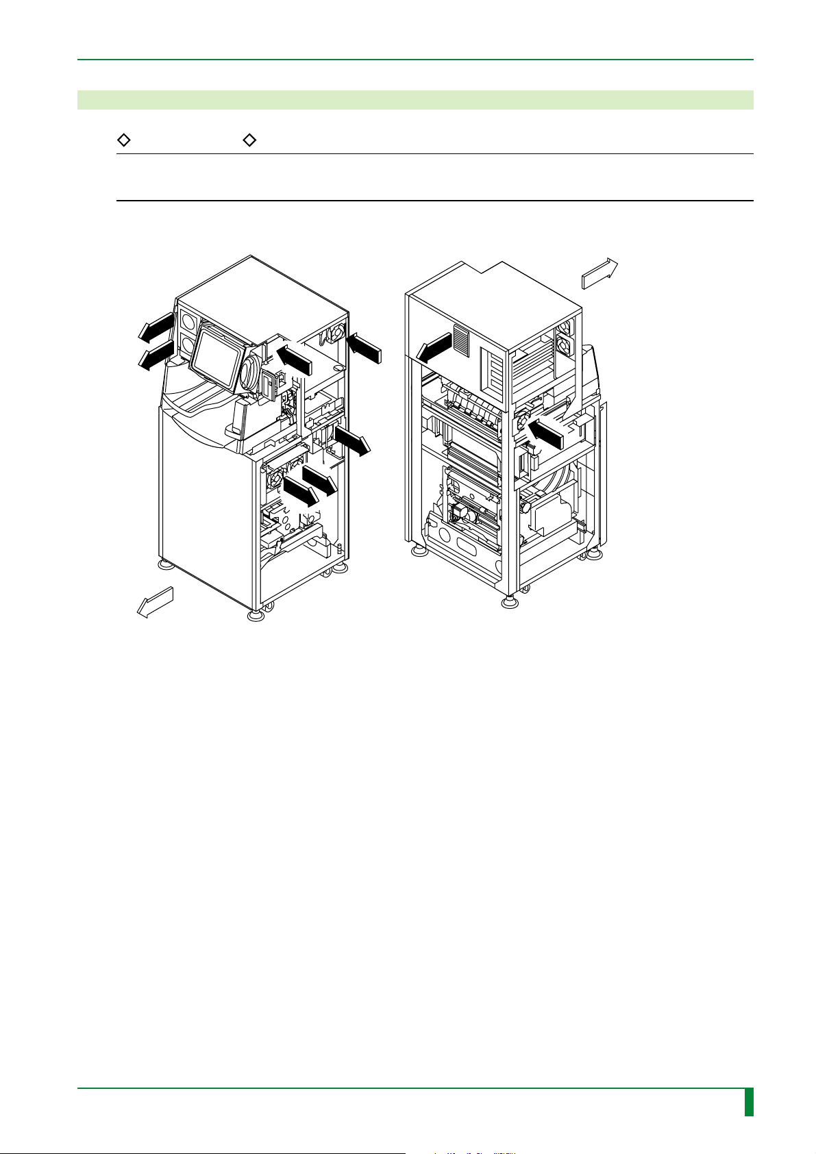
15. Checking the Fan Operation
WIND
WIND
WIND
WIND
WIND
WIND
WIND
WIND
REFERENCE
For the exhaust fan attached to the erasure lamp assembly, check its operation during IP
conveyance checks.
Check the fan operation.
FRONT
IN - 61
WIND
WIND
FRONT
WIND
WIND
WIND
WIND
WIND
WIND
WIND
FR7H7076.EPS
009-058-01
05.15.2001 FM3052
CR-IR347
Service Manual
IN - 61
Page 71
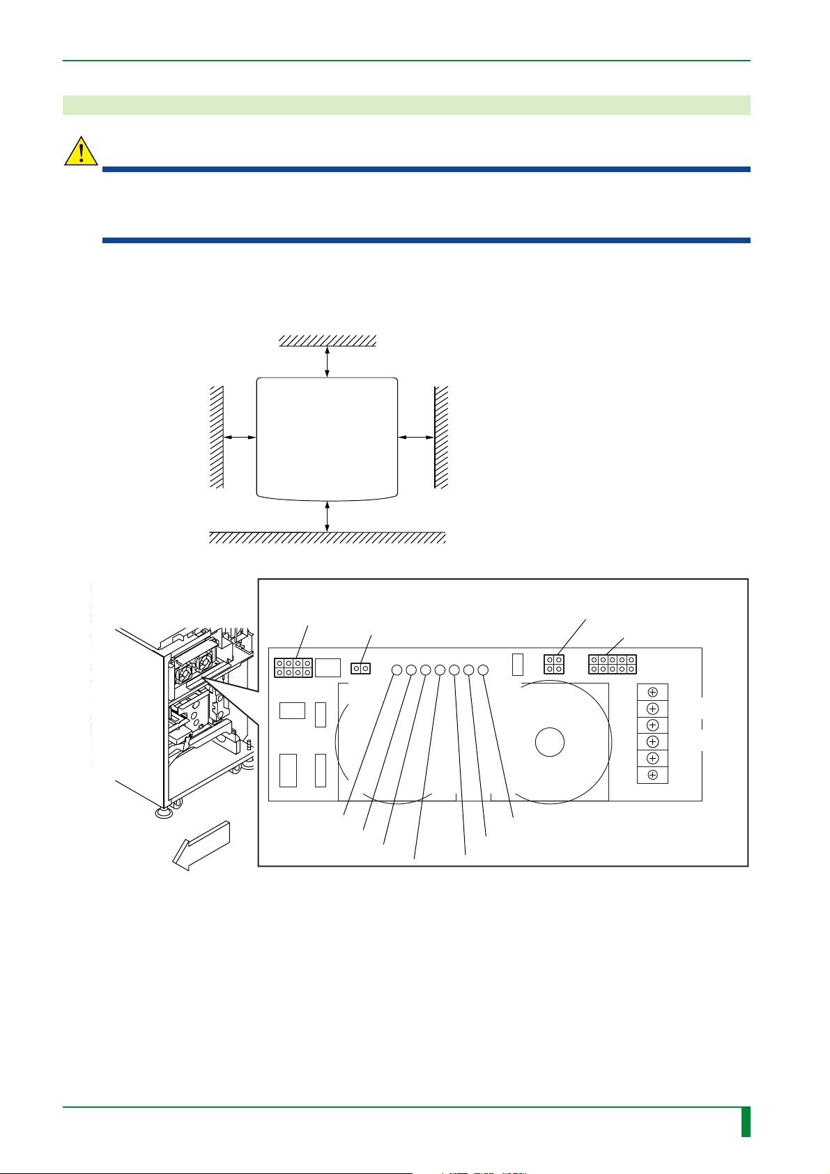
16. Measuring and Adjusting the Voltage
FRONT
FR7H7252.EPS
Power supply unit (JPS-6)
10
5
6
1
DC OUT6
DC OUT8
85
21
41
DC OUT1
DC OUT3
TB2-1(+5V)
TB2-3(GND)
TB2
—15Va
+15Vh
+24V2
+5V
+12V
+15V
+15Va
4
2
3
1
WARNING
To avoid electric shock hazards from high voltage, observe the following precautions.
• Do not touch the power supply terminals.
• When making voltage measurements, do not touch the probes (metal portions) of the tester.
Measure the voltages at the following points. If the voltage measured differs from the
specified value, rotate the associated voltage adjustment trimmer to adjust it as appropriate.
Height: 1900 or more
IN - 62
600 or more
Rear
Front
Machine
700 or more
700 or more
700 or more
Unit : mm
FR7H7016.EPS
009-058-01
05.15.2001 FM3052
CR-IR347
Service Manual
IN - 62
Page 72
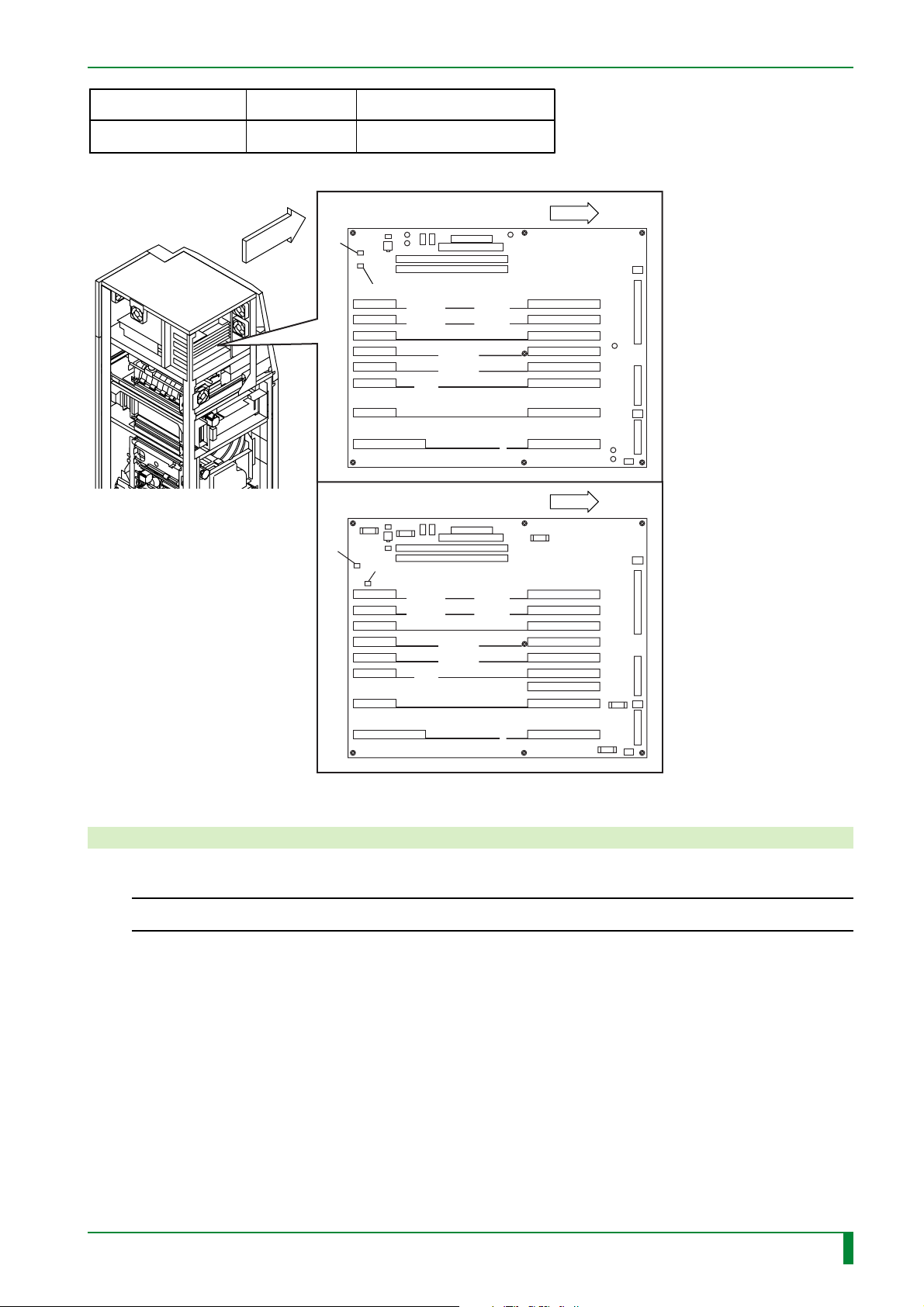
IN - 63
Measurement location
MTH08C/D TP7-TP8
Standard value
5.00 – 5.10V
MTH08C board
TP7
FRONT
MTH08D board
TP7
Voltage adjustment trimmer
+5V
TR7H7017.EPS
FRONT
TP8
FRONT
TP8
FR7H7253.EPS
17. Clearing the Backup Memory
◆
NOTE
Unless the machine is powered OFF and back ON, the backup memory will not be cleared.
◆
(1) Start the M-Utility.
(2) [8] [ENT] [1] [ENT]
(3) [1] [ENT]
➮ A message “BACKUP MEMORIES ARE CLEARED.” appears.
(4) Repeat [0] [ENT].
➮ The M-Utility quits.
(5) Turn OFF the system power switch and back ON.
009-058-03
08.30.2002 FM3476
CR-IR347
Service Manual
IN - 63
Page 73
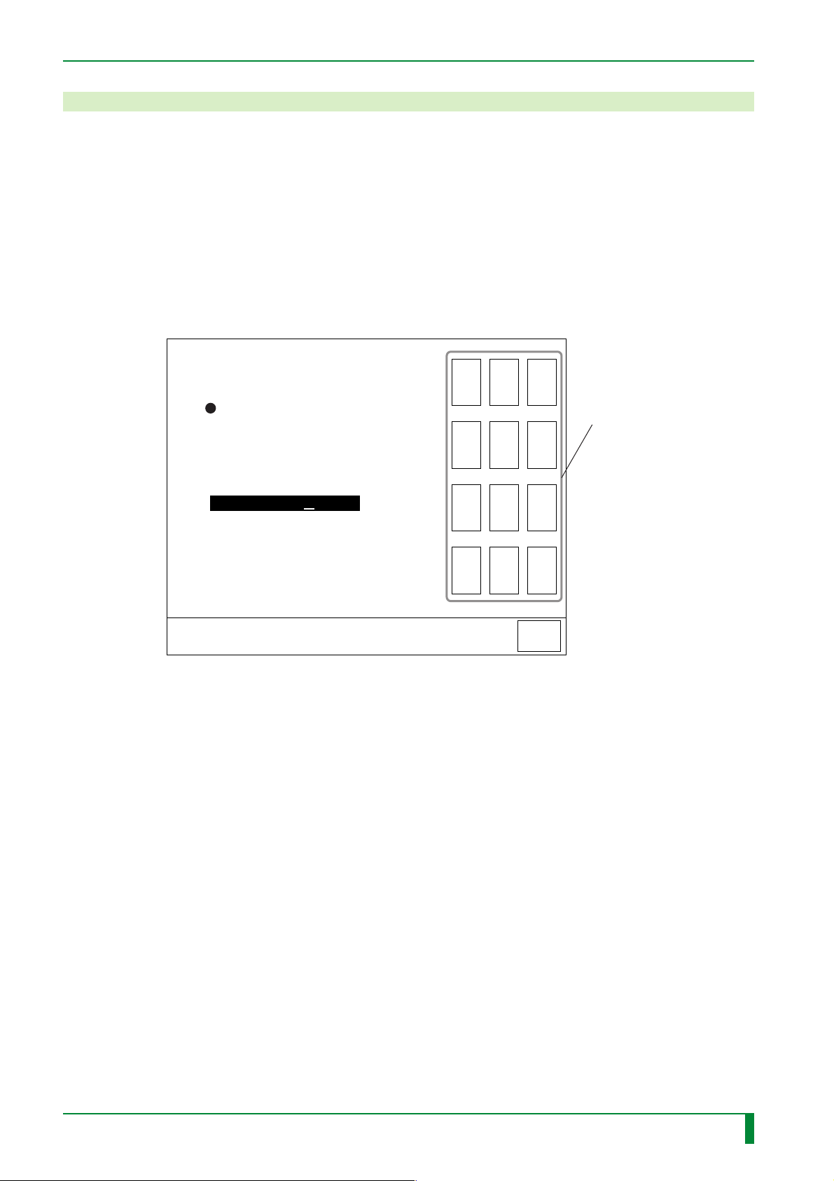
18. Setting the Date and Time
(1) Start the U-Utility.
(2) [Date/time setup]
(3) Touch the virtual keyboard to enter the current date and time.
Example) When the current date and time is April 1, 2000, 10:15 am.
[0] [0] [0] [4] [0] [1] [1] [0] [1] [5]
(4) [ENT]
➮ When the setting is confirmed, OK appears below the entry field.
If the date or time is entered incorrectly, touch the [BS] key to correct it as appropriate.
Set the new date and time
in the order of Year, Month,
Date and Time (military time)
Ex) April 1, 2000.10:15 AM
Input 0004011015
IN - 64
7 8 9
Virtual keyboard
4 5 6
(5) [Return]
0004011015
SET DATE/TIME
1 2 3
0 BS ENT
QUIT
FR7H7078.EPS
009-058-01
05.15.2001 FM3052
CR-IR347
Service Manual
IN - 64
Page 74
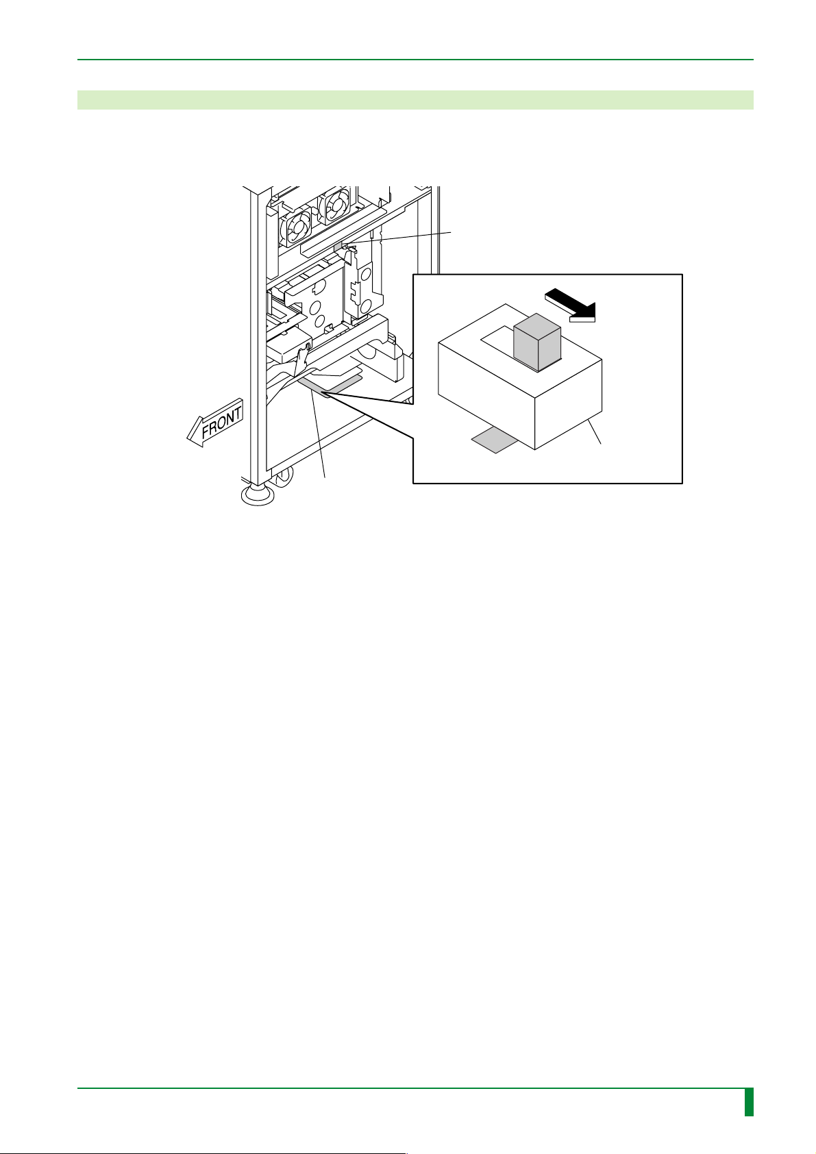
19. Turning ON the High-Voltage Switch
(1) Turn OFF the system power switch.
(2) Turn ON the high-voltage switch (S1) of the SCN08D board.
HHS label #2
S1
IN - 65
ON position
SCN08D board
HV
ON
High-voltage
switch
FR7H7114.EPS
009-058-01
05.15.2001 FM3052
CR-IR347
Service Manual
IN - 65
Page 75
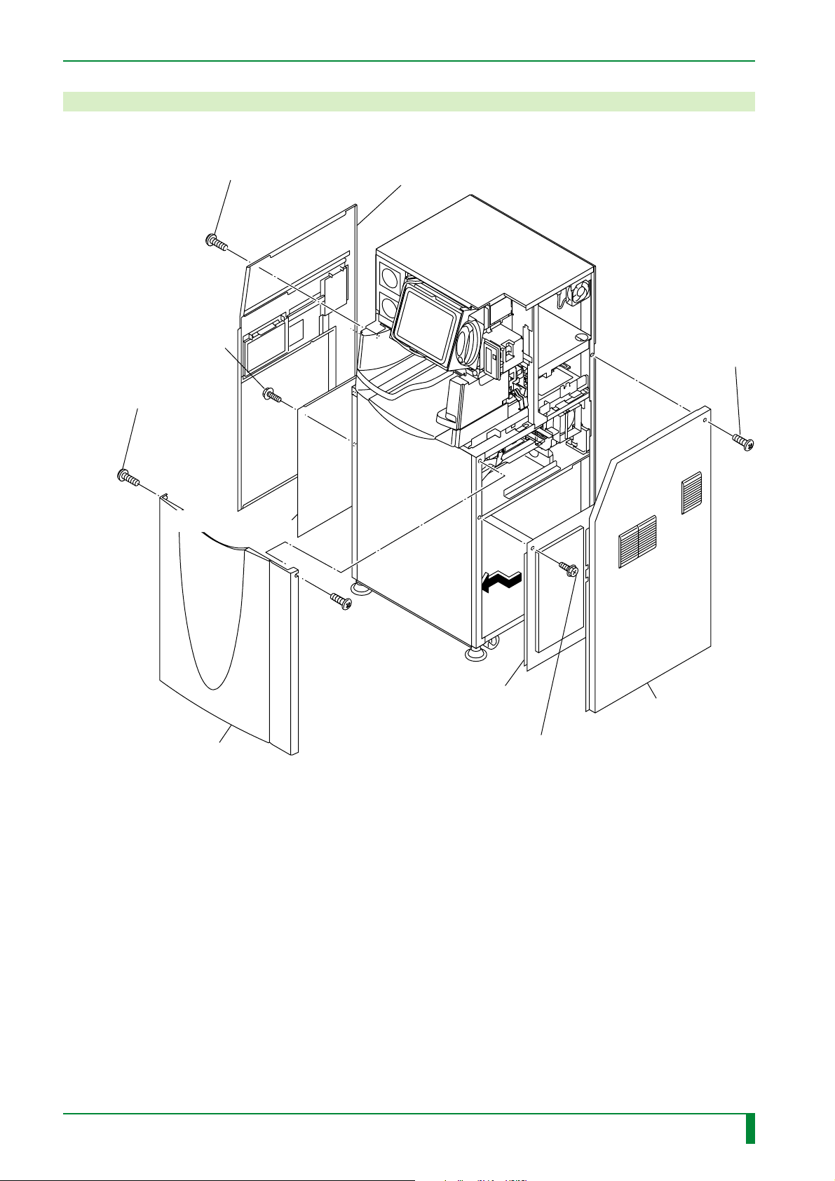
20. Installing the Covers
(1) Install the covers.
IN - 66
[Attach]
BR4x8 (x6)
[Attach]
T4x12 (x2)
(separate
packaged item)
Lower inner left-hand
[Attach]
T4x12 (x6)
T4x6 (x3)
side cover
Lower left-hand side cover
[Attach] T4x6 (x7)
Lower front cover
Right-hand side inner cover
Lower right-hand
side cover
[Attach] BR4x8 (x5)
FR7H7224.EPS
009-058-01
05.15.2001 FM3052
CR-IR347
Service Manual
IN - 66
Page 76
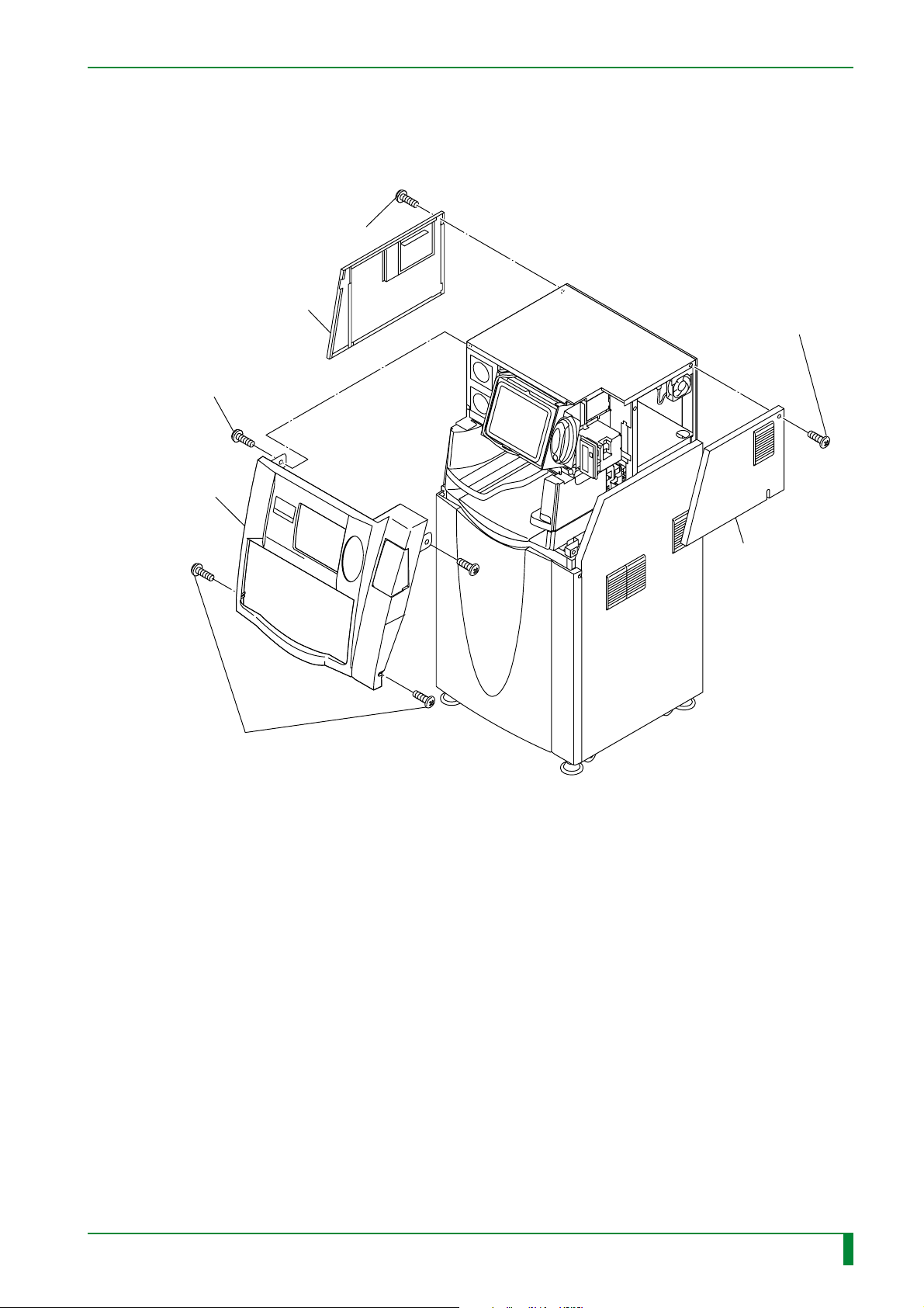
Upper left-hand side cover
[Attach]
BR4x8 (x2)
Upper front cover
IN - 67
[Attach]
T4x12 (x4)
[Attach]
T4x6 (x4)
[Attach]
T4x12 (x2)
(separate packaged item)
Upper right-hand
side cover
FR7H7225.EPS
009-058-01
05.15.2001 FM3052
CR-IR347
Service Manual
IN - 67
Page 77
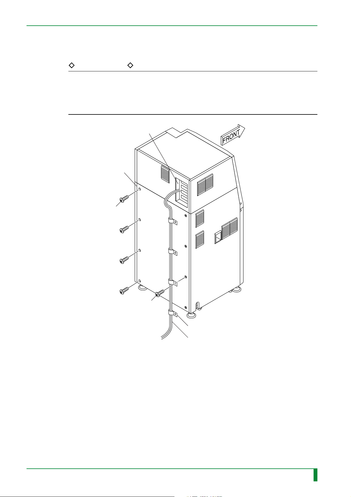
IN - 68
(2) Install the lower rear cover.
(3) Using the NK clamps (separate packaged item), secure the I/F cables onto the lower
rear cover.
REFERENCES
• The size of the NK clamps used should be determined according to the number of I/F
cables.
NK clamps that are left unused should be kept separately for later use.
• The mounting screws (T4x20), supplied as the separate packaged item, should be
used.
Controller
Lower rear cover
[Attach T4x12 (x4)
#1
[Attach] T4x20
#2
NK clamp (x4)
I/F cables
FR7H7083.EPS
009-058-01
05.15.2001 FM3052
CR-IR347
Service Manual
IN - 68
Page 78

BLANK PAGE
IN - 69
009-058-01
05.15.2001 FM3052
CR-IR347
Service Manual
IN - 69
Page 79
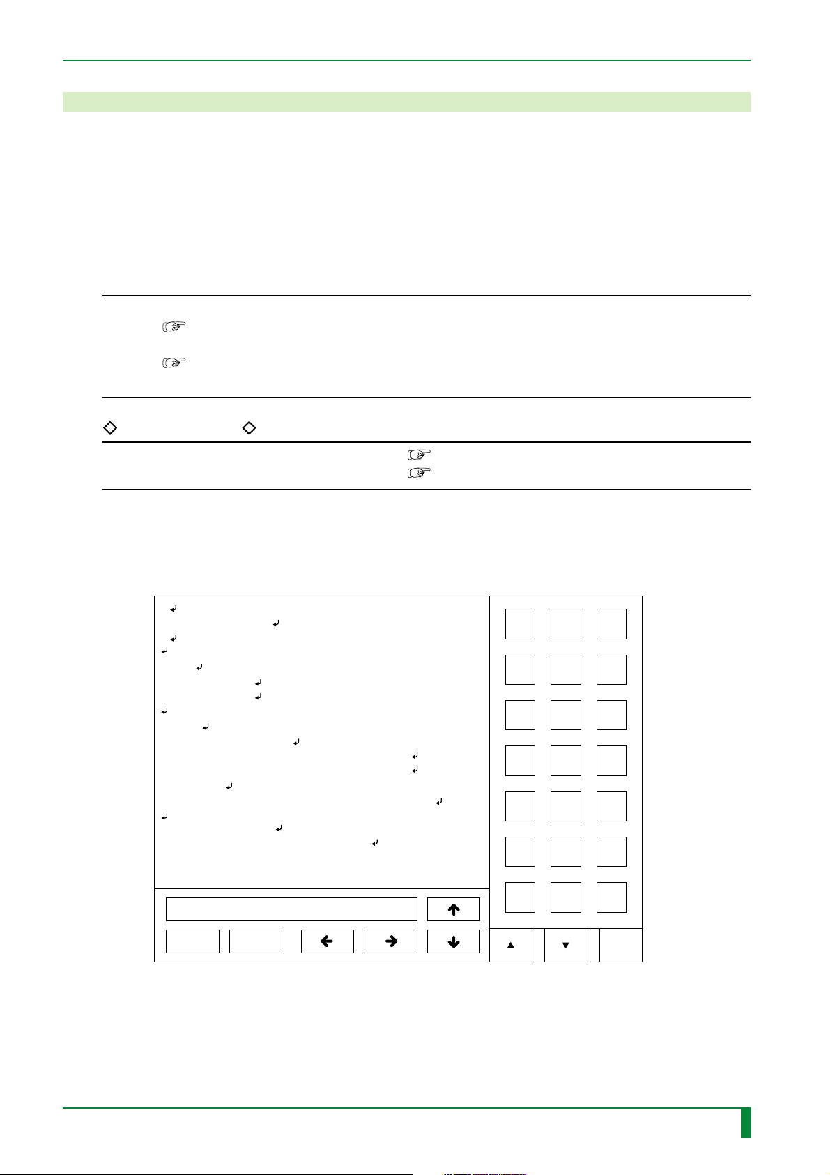
21. Setting the Configuration
This section describes the configuration items that may be set when the machine is
configured as follows.
• IDT connection
• Printer connection is implemented.
◆
INSTRUCTIONS
• For the CSL type, perform menu editor setting.
“Appendix 3. Menu Editor Setting”
• For the CL connection type, perform CR Console (CR-IR348CL) connection.
“Appendix 4 Procedures for Connecting with CR Console (CR-IR348CL) in “Installation Volume”
REFERENCES
◆
IN - 70
• When network connection is established
• When other settings are made
(1) Start the M-Utility.
(2) [2] [ENT] [1] [ENT]
#
# IRSET.ORG/CFG
#
IDT=0
#1.System Type
# 0:CSL / 1:IDT
FNT=0
#2.FONT(LANGUAGE)
# 0:JPN / 1:ENG / 2:GER / 3:FRN / 4:ESP /
# 5:ITA / 6:SWE / 7:FIN / 8:DEN / 9:NOR /
# 10:KOR
# 10:114Y5431030(Korean Option)is necessary.
IPS="172.16.0.1 "
#3.IP Address(CPU90E) (Length=15)
[Appendix 1]
[Maintenance Utility Volume]
ABC
DEF
789
456
123
0
.
SP
009-058-02
009-058-01
08.30.2001 FM3142
05.15.2001 FM3052
/sb0/SYSTEM/ETC/IRSET.CFG
SAVE
CANCEL
CR-IR347
Service Manual
DEL
BS ENT
Caps
FR7H7237.EPS
IN - 70
Page 80
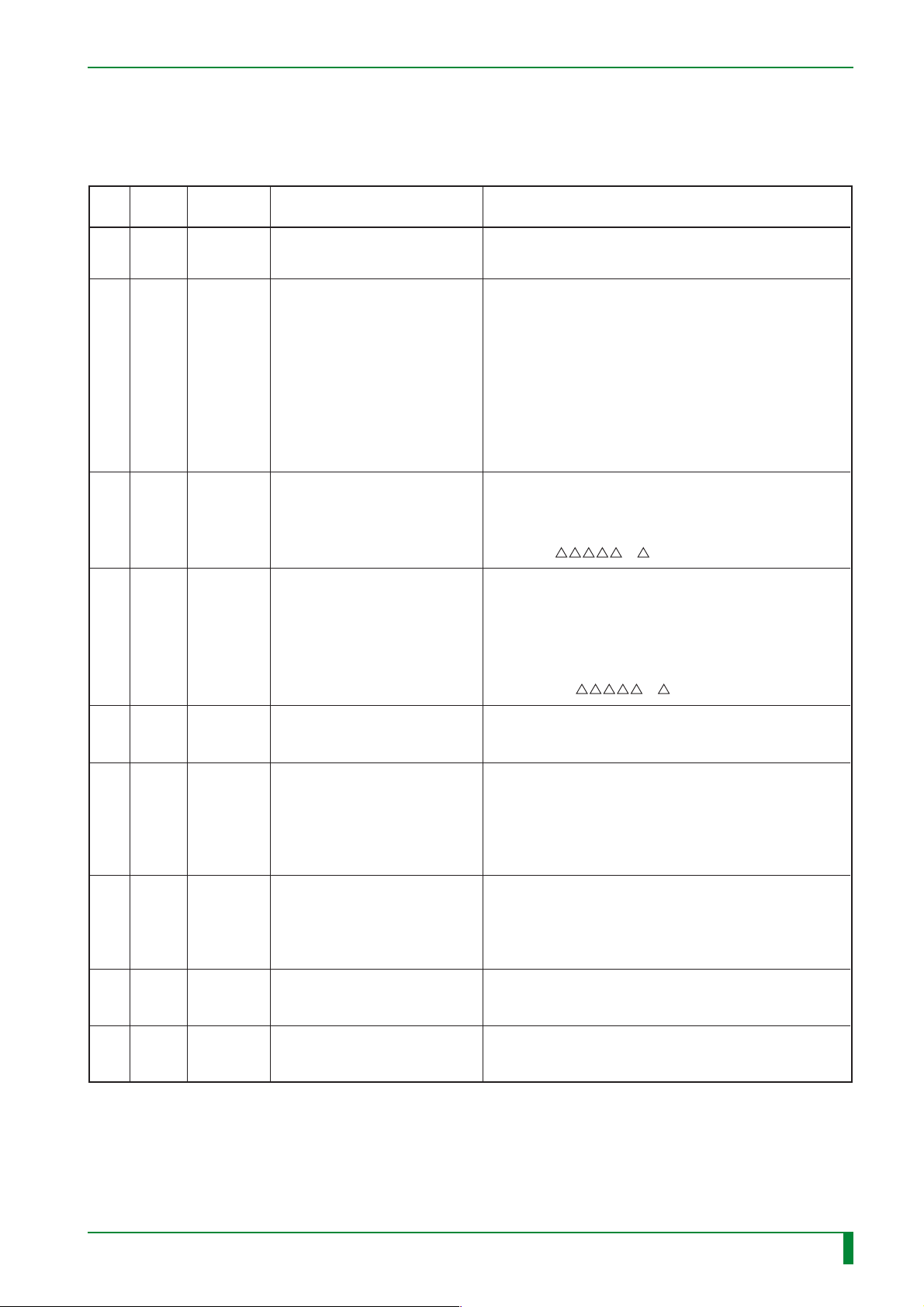
(3) Perform SYSTEM (IRSET.CFG) settings as appropriate.
● SYSTEM setup items
IN - 71
Item
Item Initial value Setup description Parameters/Remarks
No.
1 IDT 1
2 FNT 0 Language setting
3 IPS 172.16.0.1
4 IPI 172.16.0.2
Switching between IDT connection
type and CSL function built-in type
IP address of the CPU90E board
(IP address for network
connection)
IP address of the CPU90F board
(IP address for network
connection)
0: CSL
1: IDT
0: Japanese
1: English
2: German
3: French
4: Spanish
5: Italian
6: Swedish
7: Finnish
8: Danish
9: Norwegian
10: Korean (optional software required)
<NOTE>
The setup value should always be described in fifteen digits
justified to the left. If the number of digits is less than 15,
space should be added to meet the 15-digit requirement.
“172.16.0.1 ” ( : space)
<NOTES>
• The setup value should always be described in fifteen
digits justified to the left. If the number of digits is less
than 15, space should be added to meet the 15-digit
requirement.
• The IP address should always be set even if the CPU90F
board (optional) is absent (default value).
“172.16.0.2 ” ( : space)
5 ILA 1
8 SID A
12 XRY 0
37 PCL
ID_
44
DST
(4) Touch [SAVE].
CPU board setting for the IDT
connection destination
Reader number
(A through Z: Unique symbol)
Message setting for overexposed
IP reading
0 Clock during LP-I/F output
0 Distribution code setting
0: CPU90E
1: CPU90F (optional)
<REFERENCE>
When multiple FCR readers are connected within the same
network, a unique symbol (A through Z) is assigned to each
of the readers, so that it is displayed as the first digit of the
image number on the output form, to which the reader of the
image data designation can respond.
0: LOG & MESSAGE
1: LOG ONLY
2: NONE
<NOTE> Setting change is prohibited.
0: 1µ sec (<60m)
1
:
2µ sec (>60m)
0: DISABLE
1: ENABLE
TR7H7014.EPS
009-058-02
009-058-01
08.30.2001 FM3142
05.15.2001 FM3052
CR-IR347
Service Manual
IN - 71
Page 81
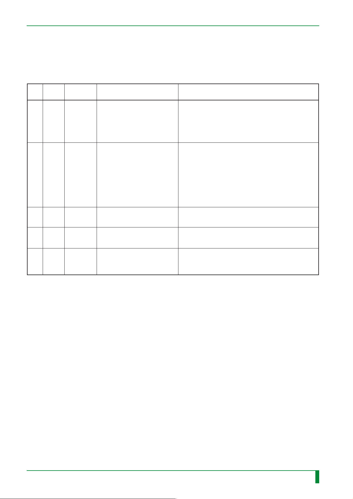
(5) [2] [ENT]
(6) Perform PRINT (FILMFMT.CFG) settings as appropriate.
● PRINT setup items
IN - 72
Item
Item Initial value Setup description Parameters/Remarks
No.
6HN
7HP
35
35
37 EM 2
FD
1824A
FD
1824B
FUJI FILM
HOSPITAL
9578 8E6D
8374 8343
838B 8380
9561 8940
8140 8140
8140 8140
8140 8140
8140
0020
1030
Institution name
Institution name in Kanji
Position rotation designation
for 18 x 24 cm (left-hand
image) areas 0 and 1
Position rotation designation
for 18 x 24 cm (right-hand
image) areas 0 and 1
"Ene.-Sub." parameter/PEM
parameter output.
60 characters
<REFERENCE>
It indicates the institution name displayed when “2.
FNT” of SYSTEM is set to other than “0”.
S-JIS 30 bytes (up to 15 full-width characters)
<REFERENCES>
• It indicates the institution name displayed when “2. FNT”
of SYSTEM is set to other than 0".
• To enter an institution name in Kanji, the Shift-JIS code
should be entered with every four digits delimited by space.
It should be noted that if 15 characters of Shift-JIS space
code (8140) are entered in “7. HP”, the institution name
that is set in “6. HN” is displayed.
The area position rotation is specified
by four digits.
The area position rotation is specified
by four digits.
0: NO
1: YES (Ene.-Sub.)
2: YES (PEM)
TR7H7015.EPS
009-058-01
05.15.2001 FM3052
CR-IR347
Service Manual
IN - 72
Page 82
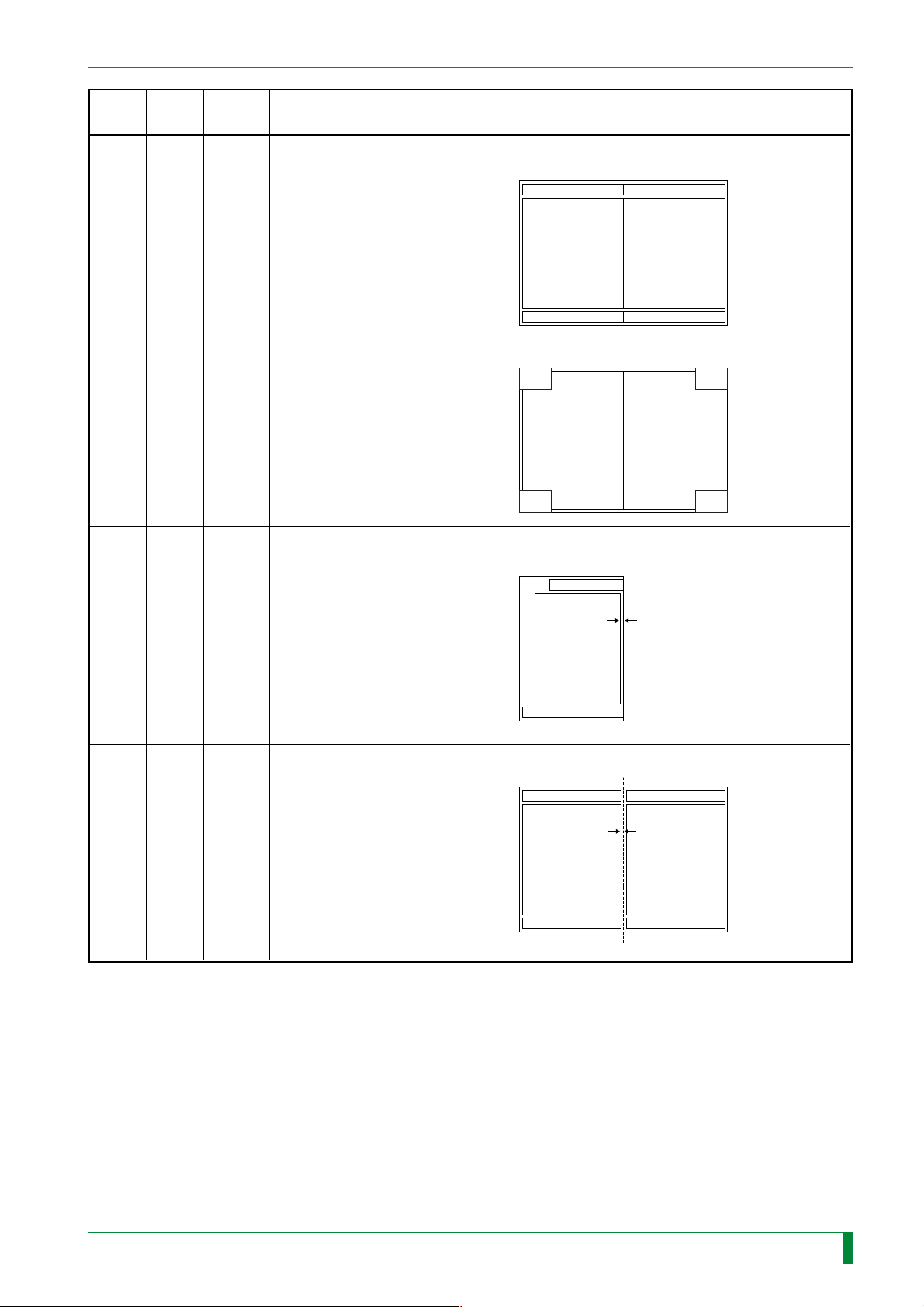
IN - 73
43 MFG1
Single mammo format image
interval setting
0-50 (0.1 mm)
0
Image
42 MBF 1
18x24cm 2-on-1 mammo format
image scaling factor setting
0: 86%/1: 100%
<Format for 0:86%>
<Format for 1:100%>
Left image
Right image
Left image
Right image
Item
Initial
value
Setup description
Parameters/Remarks
Item
number
44 MFG2
2-on-1 mammo format image
interval setting
0-50 (0.1 mm)
0
Left image
Right image
TR7H7018.EPS
009-058-01
05.15.2001 FM3052
CR-IR347
Service Manual
IN - 73
Page 83
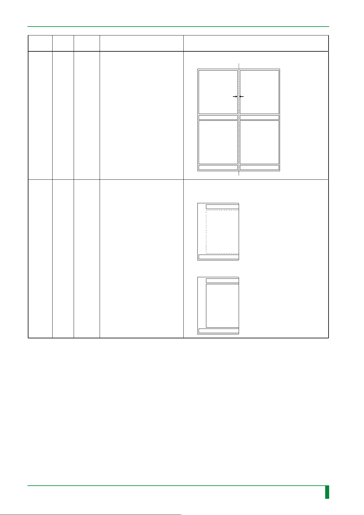
IN - 74
Item
number
45 MFG4
Item
Initial
value
0
Setup description
4-on-1 mammo format
image interval setting
Parameters/Remarks
0-50 (0.1 mm)
Image
Image
0: Without image frame
<0: Without image frame>
/
Image
Image
1: With image frame
46 MFR1
Image
1
Single mammo format image
frame setting
<1: With image frame>
Image
TR7H7019.EPS
009-058-01
05.15.2001 FM3052
CR-IR347
Service Manual
IN - 74
Page 84
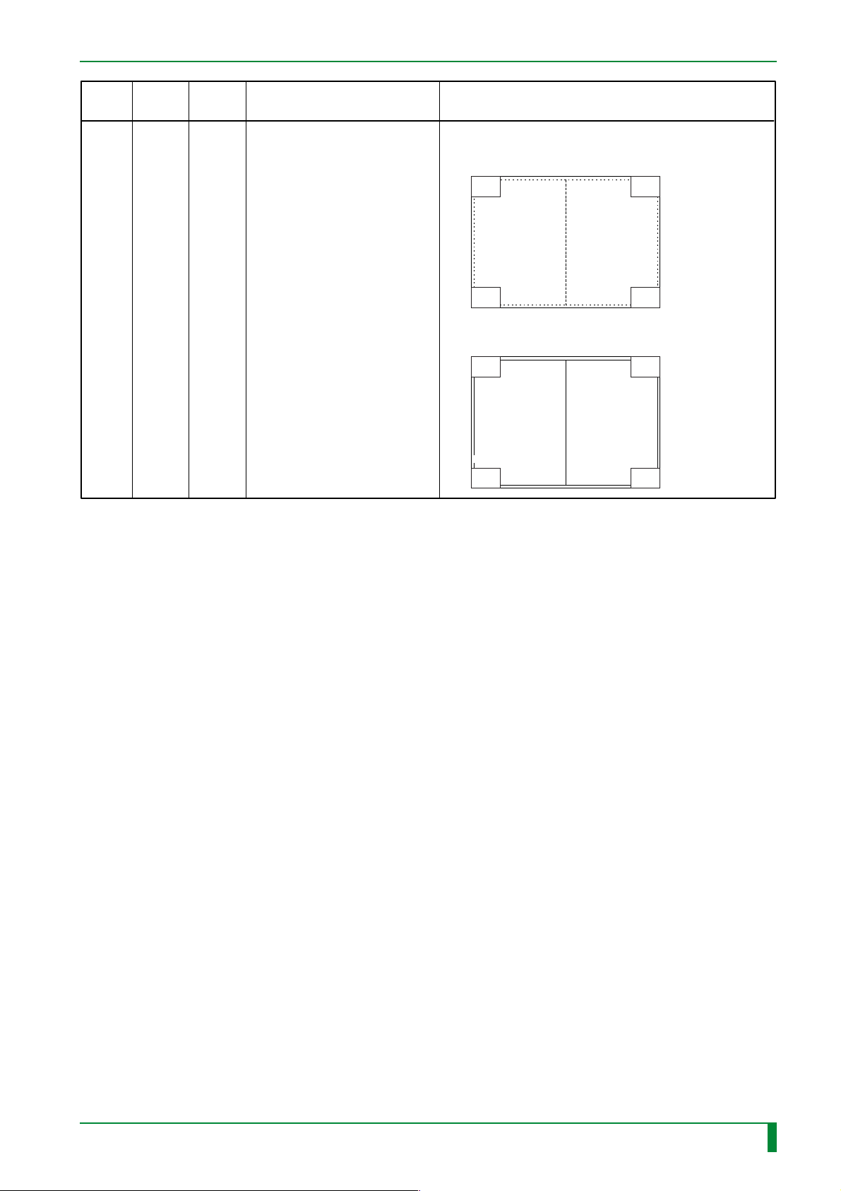
IN - 75
47 MFR2
2-on-1 mammo format image
frame setting
<0: Without image frame>
0: Without image frame/1: With image frame
<1: With image frame>
1
Left image
Right image
Left image
Right image
TR7H7020.EPS
Item
Initial
value
Setup description
Parameters/Remarks
Item
number
(7) Touch [SAVE].
(8) Turn OFF the system power switch and back ON.
009-058-01
05.15.2001 FM3052
CR-IR347
Service Manual
IN - 75
Page 85
22. Checking for Image Problems
■ Check for Nonuniformity, Sensitivity, and Density
(1) Expose two IPs of all sizes found at the institution (both ST and HR types). Expose the
first in the normal direction, and the second in a 180-degree rotated orientation.
The IP exposure conditions are as follows.
❍ ST
• Dose: 1 mR
• X-ray tube target : Tungsten
• Distance: 1.8 m
• Voltage: 80 kV
• Current: 50 mA
• Time: 0.013 sec
❍ HR
• Dose: 20 mR
IN - 76
• X-ray tube target/filter: Molybdenum/molybdenum
• Distance: 0.55 m
• Voltage: 28 kV
• Current: 100 mA
• Time: 0.053 sec
(2) Using the test menu, record and output an image.
❍ ST
“
” (for Japanese version)/“SENSITIVITY” (for versions other than Japanese)
❍ HR
“
(for versions other than Japanese and U.S.)
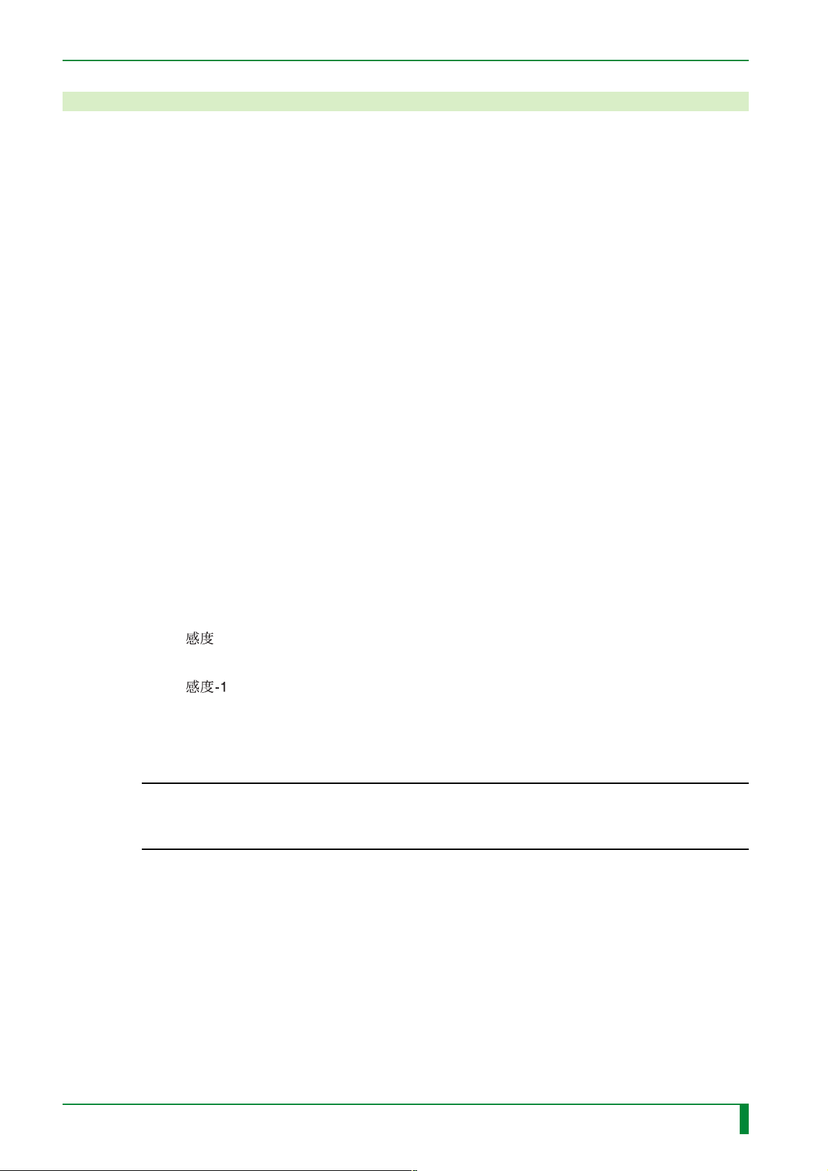
(3) Check to ensure that there is no nonuniformity on the output film or the image on the
image monitor .
◆
CHECK
” (for Japanese version)/“SensitivityHQ” (for U.S. version)/“SENSITIVITY2”
◆
Check for nonuniformity.
If any nonuniformity is found, refer to “10. Troubleshooting Procedures Based on
Abnormal Image” in the “Troubleshooting” volume.
009-058-03
08.30.2002 FM3476
CR-IR347
Service Manual
IN - 76
Page 86
IN - 77
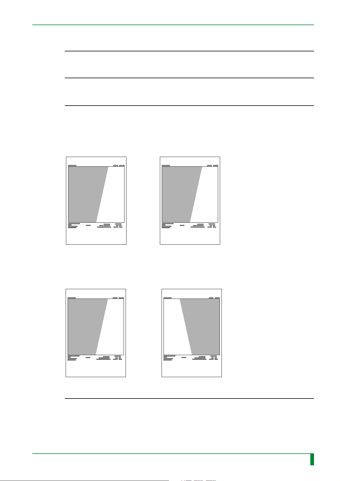
(4) Using the output film, check the sensitivity.
◆
CHECK
Make sure that the S value on the film is held within the following range.
ST: 140
HR: 84
(5) Make sure that there is no density unbalance in the image of the output film.
◆
CHECK
Make sure that there is no density unbalance in the main scan direction.
If any density unbalance is found, compare the films outputted from two IPs of the same
size to isolate its probable cause.
• If the density unbalance positions in the main scan direction are the same
➮
The culprit is an improper mounting of the light-collecting guide assembly.
◆
≤
S value ≤ 260
≤
S value ≤ 156
◆
IP in normal orientation (first) IP in 180-degree rotated
orientation (second)
FR7H3746.EPS
• If the density unbalance positions in the main scan direction are different
➮
The exposure-related component(s) may be a probable cause.
IP in normal orientation (first) IP in 180-degree rotated
orientation (second)
FR7H3747.EPS
009-058-03
08.30.2002 FM3476
CR-IR347
Service Manual
IN - 77
Page 87
■ Check for Jitter and HR
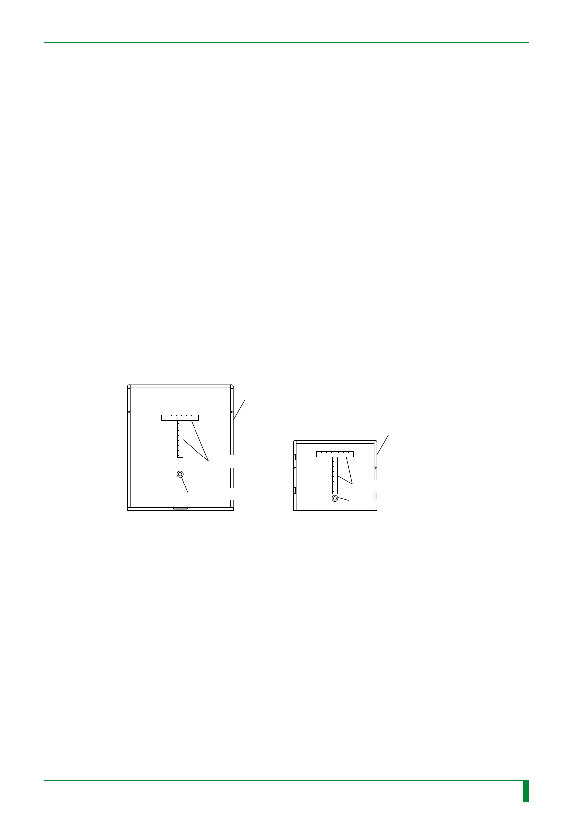
(1) Place steel rules and a washer on IPs of all sizes found at the institution, and expose
them. (Both ST and HR types. For the layout, see the illustration below.)
The IP exposure conditions are as follows.
❍ ST
• Dose: 1 mR
• X-ray tube target : Tungsten
• Distance: 1.8 m
• Voltage: 80 kV
• Current: 50 mA
• Time: 0.013 sec
❍ HR
• Dose: 20 mR
• X-ray tube target/filter: Molybdenum/molybdenum
• Distance: 0.55 m
• Voltage: 28 kV
IN - 78
• Current: 100 mA
• Time: 0.053 sec
The layout of the steel rules and washer is shown below.
Cassette
Steel rules (150mm)
Washer (ø8–15)
14" x 17"
24cm x 30cm mammo
Steel rules (150mm)
Washer (ø8–15)
Cassette
FR7H6950EPS
009-058-03
08.30.2002 FM3476
CR-IR347
Service Manual
IN - 78
Page 88
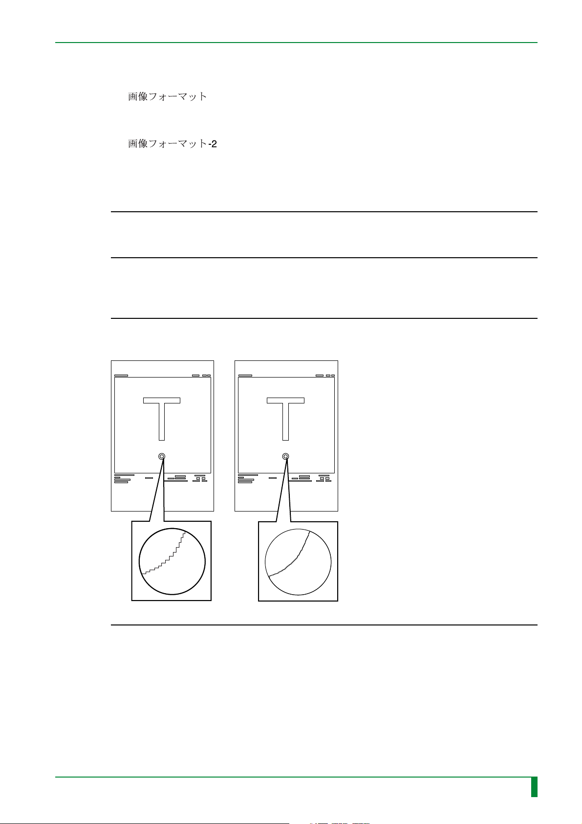
(2) Using the test menu, record and output an image.
❍ ST
IN - 79
“
” (for Japanese version)/“IMAGE FORMAT” (for versions other than
Japanese)
❍ HR
“
” (for Japanese version)/“BREAST, L (DSR)” or “BREAST, R (DSR)”
(for U.S. version)/“IMAGE FORMAT2” (for European version)
(3) Make sure that there is no jitter in the image of the border and steel rules on the output
film.
◆
CHECK
◆
Check for jitter.
If any jitter is found, refer to “10. Troubleshooting Procedures Based on Abnormal Image”
in the “Troubleshooting” volume.
(4) Compare the images of the washer for ST and HR to ensure that the image for HR is
smoother.
◆
CHECK
◆
Using a loupe, make sure that the image of the washer’s curvature for HR appears
smoother than that for ST.
009-058-03
08.30.2002 FM3476
ST HR
CR-IR347
FR7H6965.EPS
Service Manual
IN - 79
Page 89
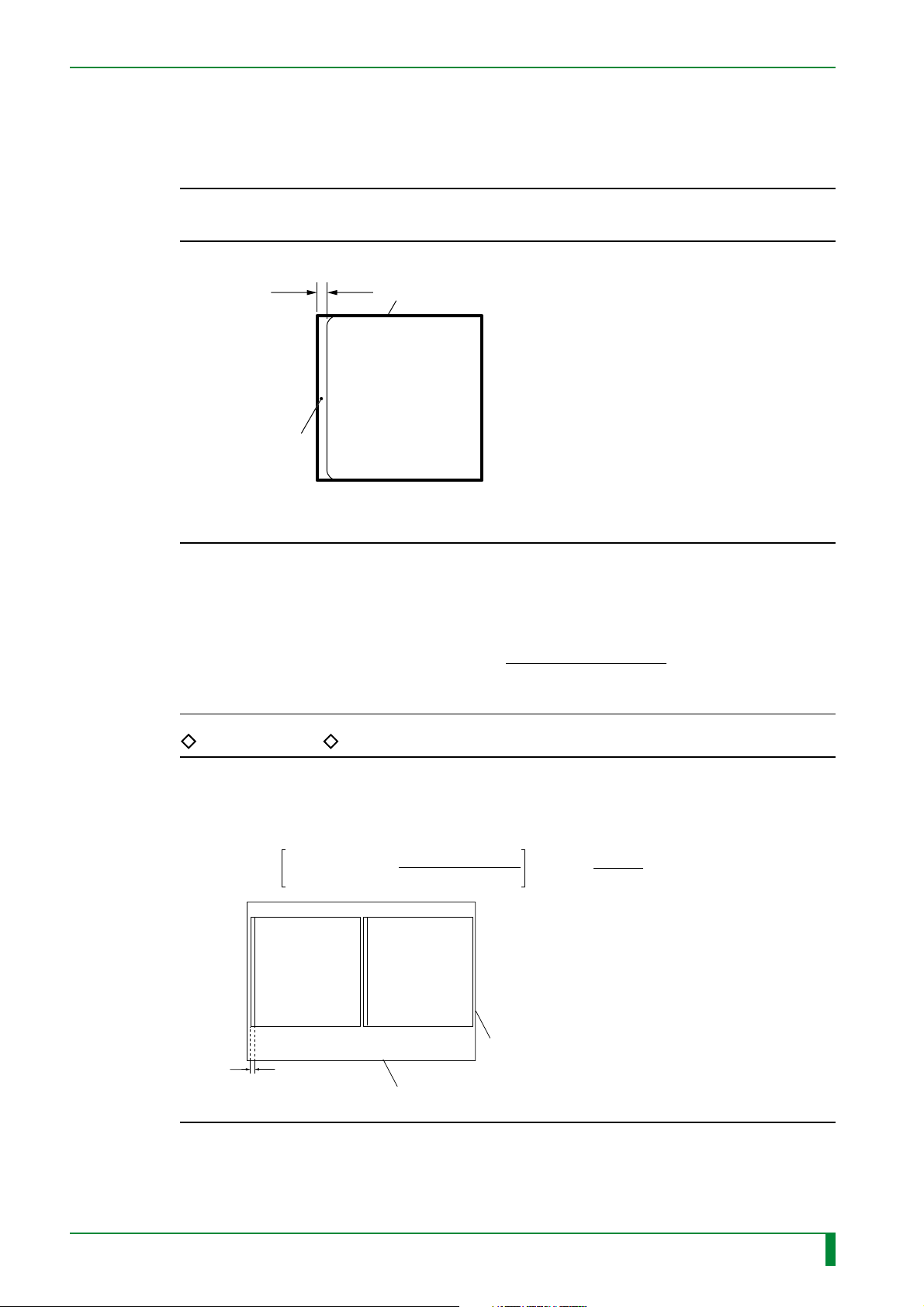
■ Check for Format
Make sure that the white blank portion, as measured from the outermost side of the image
border of the output film, is 2 mm or less in actual size on the IP.
◆
CHECK
Make sure that the white blank portion is 2 mm or less.
If anything abnormal is found, refer to the “Troubleshooting” volume.
White blank portion
IN - 79.1
◆
2 mm or less
Image border
FR7H6055.EPS
◆
NOTE
◆
The distance measured on the film may differ from the actual size on the IP, depending
on the reading size or film size. Using the distance measured on the film and the
reduction factor for the film, calculate the actual size on the IP. Compute the actual
size on the IP according to the following formula.
Actual size on IP = Measured value x
Reduction factor (%)
100
TR7H6010.EPS
REFERENCE
For example, when a two-in-one image of 14"x14" (35cm x 35cm) is outputted to B4
film, the resulting reduction factor is 50%. If the distance measured on the film is 1
mm, then actual size on the IP is 2 mm. Calculate the distance in actual size on the IP
as shown below.
Actual size on IP: Measured value x =1 (mm) x = 2 (mm)
100
Reduction factor (%)
100
50 (%)
009-058-03
08.30.2002 FM3476
1mm
■ 50%
The reduction factor is indicated here.
CR-IR347
Service Manual
Film
FR7H6960.EPS
IN - 79.1
Page 90
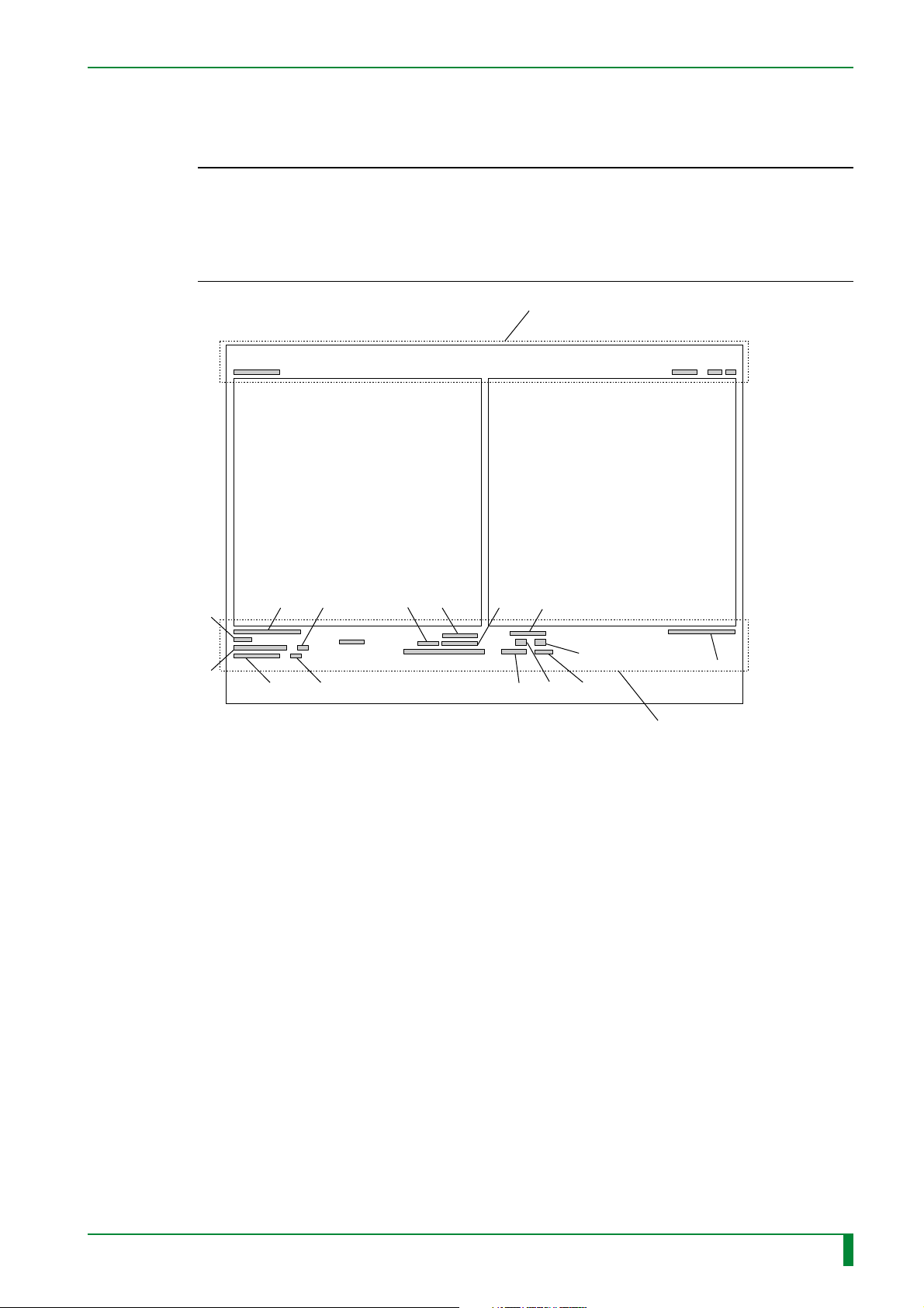
■ Check for Output Characters
Make sure that the output characters are indicated correctly on the output film.
◆
CHECKS
• Make sure that the output characters are indicated correctly.
If anything abnormal is found, refer to “4. [2] CONFIGURATION SETTING” in the
“Maintenance Utility” volume.
• Ensure that there is nothing abnormal with the output characters.
If anything abnormal is found, refer to the “Troubleshooting” volume.
◆
IN - 79.2
In normal two-image output mode
a
Image
f
e
j
i
g
th
❍ Character display area A
(above the image area)
a: Hospital name
(institution name)
b: IP number
c: EDR mode and menu code
d: System ID and image number
Character display area A
k n
ls
m
❍ Character display area B
(below the image area)
e: Image processing conditions
f: Exposure menu name
g: Standardization conditions
h: Engineer code and exposure
i: Department name
j: Patient ID
k: Patient name (kana)
l: Patient name (kanji)
m: Exposure date and time
n: Film mark
o: Sex
p: Age or birth date
q: Image reduction ratio
r: Set processing information
s: Left-right reversal mark ( )
t: Data compression code
u: PEM information or
bc
Image
p
o
rq
Character
display area B
and amendments
table information
Ene.-Sub./superposition
information
d
u
R
009-058-03
08.30.2002 FM3476
CR-IR347
Service Manual
FR7H6962.EPS
IN - 79.2
Page 91

BLANK PAGE
IN - 79.3
009-058-03
08.30.2002 FM3476
CR-IR347
Service Manual
IN - 79.3
Page 92

BLANK PAGE
IN - 79.4
009-058-03
08.30.2002 FM3476
CR-IR347
Service Manual
IN - 79.4
Page 93
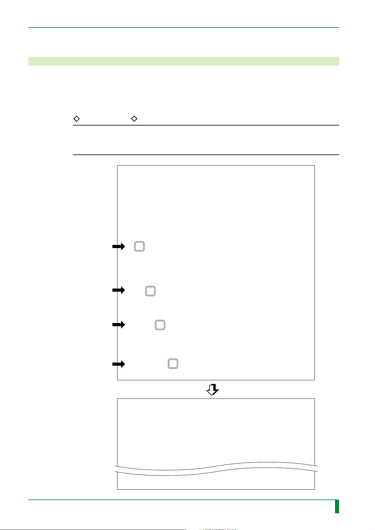
IN - 80
23. Checking and Deleting the Error Log during Setup
23.1 Checking the Error Log
(1) Start the M-Utility.
(2) Open the error log.
REFERENCE
Below is shown an example where errors and warning messages are displayed. To
check the number of occurrences for each error code, select “2. SUMMARY”, instead
of “1. ALL”.
0. QUIT
1. ERROR LOG UTILITY
2. CONFIGURATION SETTING
3. TEST MODE
4. ELECTRICAL UTILITY
5. SCANNER UTILITY
6. MECHANICAL UTILITY
7. FILE UTILITY
8. BACKUP MEMORY
9. HV OFF
10. MENU SETTING
#1 [Input/ENT]
11.SYSTEM UTILIT
> 1
Y
#2 [Input/ENT]
#3 [Input/ENT]
#4 [Input/ENT]
0. QUIT
1. LIST
2. CLEAR
3. SAVE TO FD
4. SAVE TO HD
ELU > 1
0. QUIT
1. ALL
2. SUMMARY
ELU : LI > 1
0. QUIT
1. ERROR
2. WARNING
3. BOTH
ELU : LI : ALL > 3
CODE DATE
081D 1998.04.16 14:36
11.E738.000002.8A0AC1.000000.000
C19.8
000001.000009.00001B
.
.
.
1722 1998.04.16 09:58
85AA1319.05972166
009-058-01
05.15.2001 FM3052
0.END 1.NEXT 2.BEFORE (DEFAULT=1) :
CR-IR347
Service Manual
FR7H7115.EPS
IN - 80
Page 94
(3) Check the error log displayed, and make sure that no error logs are generated during
this installation procedure.
◆
CHECK
◆
Check to ensure that no error logs are generated.
If error logs are generated, see [Troubleshooting Volume].
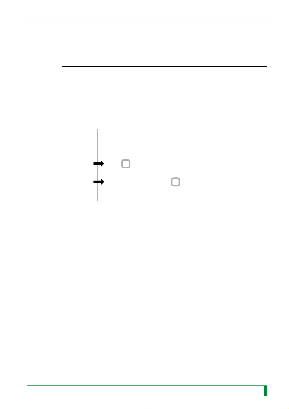
23.2 Deleting the Error Log
If no error logs are generated, the error logs, if any, prior to the installation, should be
deleted.
(1) [0] [ENT] [0] [ENT] [0] [ENT]
(2) Delete the error log.
0. QUIT
1. LIST
2. CLEAR
3. SAVE TO FD
4. SAVE TO HD
#1 [Input/ENT]
ELU > 2
IN - 81
ARE YOU SURE TO CLEAR ERROR LOGS?
#2 [Input/ENT]
1. YES 2. NO (DEFAULT=2) : 1
ERROR LOGS ARE CLEARED.
➮ When all the error logs are deleted, a message “ERROR LOGS ARE CLEARED.”
appears.
(3) [0] [ENT] [0] [ENT]
(4) [Return]
FR7H7116.EPS
009-058-01
05.15.2001 FM3052
CR-IR347
Service Manual
IN - 81
Page 95

24. Powering OFF
(1) Turn OFF the system power switch.
(2) Make sure that the system, as well as any external device connected to it, powers OFF
normally.
25. Cleaning the Covers
Clean all the covers with a moistened cloth.
IN - 82
009-058-01
05.15.2001 FM3052
CR-IR347
Service Manual
IN - 82
Page 96
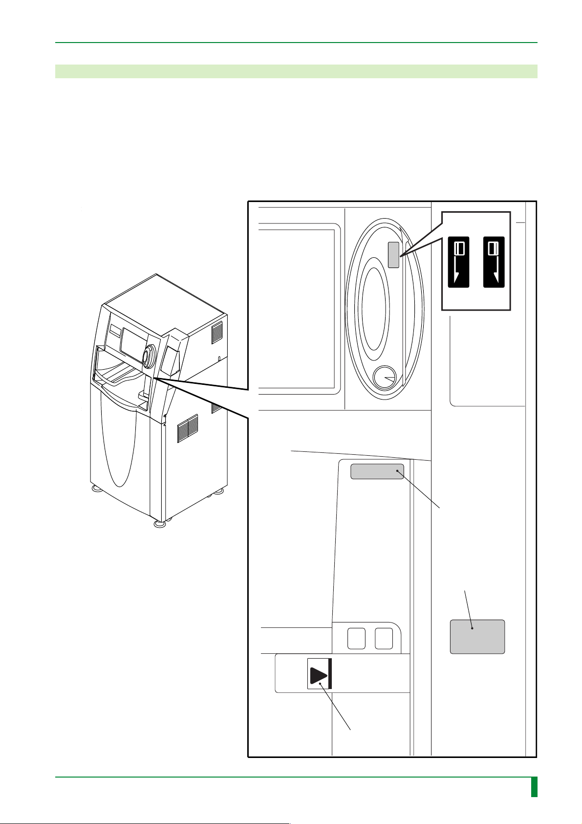
26. Attaching the Labels
Referring to the dimensional values for attachment locations illustrated below, attach the
labels, supplied as the separate packaged item, to the cover.
❏ Exposure markers precaution label 1
❏ Cassette insertion precaution label 1
❏ Arrow indication label 1
❏ MCR label (for CSL type only) 2 (JIS and ISO)
IN - 83
JIS ISO
MCR label
009-058-01
05.15.2001 FM3052
CR-IR347
Service Manual
Exposure markers
precaution label
Cassette insertion
precaution label
Arrow
indication label
FR7H7100.EPS
IN - 83
Page 97
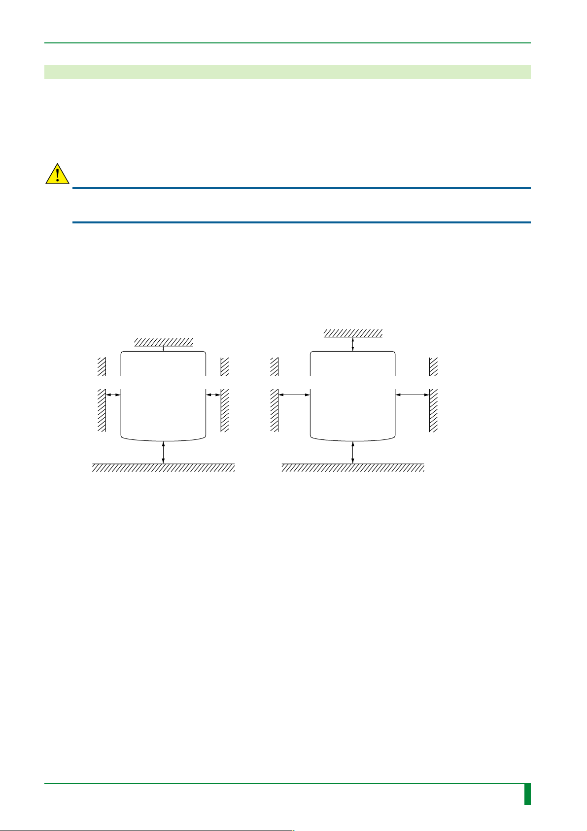
27. Final Placement
For final placement, there are two installation methods. One is to install the machine by
securing it with the clamps that were removed at the time of unloading, and the other is to
install the machine without using such clamps. Check the space available for installation,
and consult with the user about his wishes before choosing between the above two
installation methods.
CAUTION
In order to avoid electric shock hazards, power OFF the machine before performing any
procedures.
■ Installation Space Required for Final Placement
The space required for final placement differs depending on whether the machine is to be
secured with the clamps or not.
When not secured by the clamps When secured by the clamps
Height: 1800 or more
Height: 1800 or more
IN - 84
Rear
Front
Machine
700 or more
50 or more
Rear
700 or more 700 or more200 or more 200 or more
Machine
Front
100 or more
700 or more
Unit: mm
FR7H7084.EPS
009-058-01
05.15.2001 FM3052
CR-IR347
Service Manual
IN - 84
Page 98
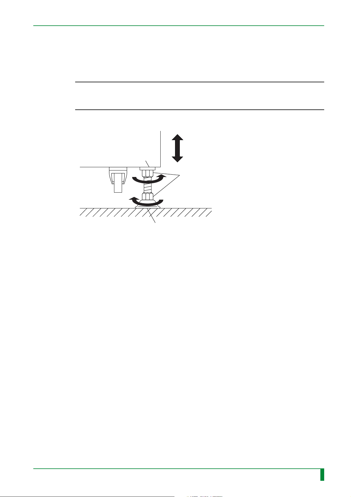
27.1 Securing the Machine with the Adjustable Feet
(1) Bring the four adjustable feet down onto the floor.
(2) Using a wrench, rotate the lower nut of the adjustable foot to adjust its height.
◆
NOTES
• Lower the adjustable feet until the casters are lifted off the floor.
• Make sure that all the four adjustable feet are used.
• Rotate the four nuts evenly.
(3) Push the upper nut of the adjustable foot against the machine and secure it in place.
Seating face on the frame side
◆
Machine
Nut
IN - 85
Adjustable foot
FR7H7085.EPS
009-058-01
05.15.2001 FM3052
CR-IR347
Service Manual
IN - 85
Page 99
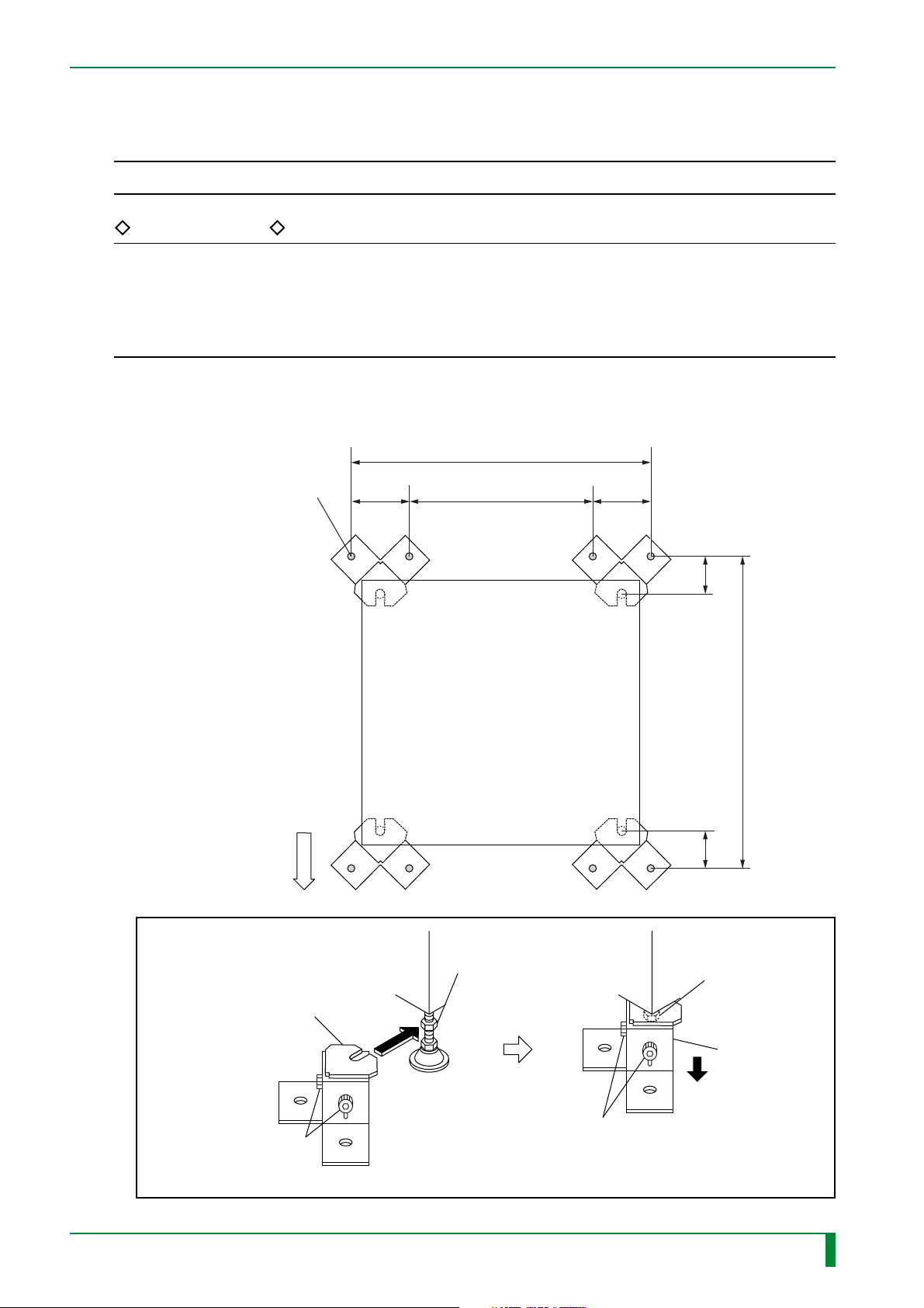
27.2 Securing the Machine with the Clamps
◆
NOTE
Before drilling holes for embedding the anchor nuts, wear protective goggles.
REFERENCES
• If the rear clamps are not tightened by the adjustable foot nuts, the machine can be
repositioned as needed for maintenance or like purposes simply by removing the two front
clamps.
• If the rear of the machine cannot be provided with an adequate space for clamp installation,
tighten the two front clamps only.
◆
(1) Determine the locations for embedding the anchor nuts.
(2) Mark the floor surface to indicate the clamp hole locations.
(755.2)
IN - 86
Anchor hole location
F
R
O
N
T
125.2
504.8 125.2
Machine
78.878.8
769.7
Unit: mm
Hex socket head bolt (x2)
009-058-01
05.15.2001 FM3052
#3
[Attach] Clamp
#1
[Loosen]
CR-IR347
#2
[Lower] Nut
#6
[Tighten]
Hex socket head bolt (x2)
Service Manual
#4
[Raise] Nut
#5
[Lower] Clamp
FR7H7086.EPS
IN - 86
Page 100
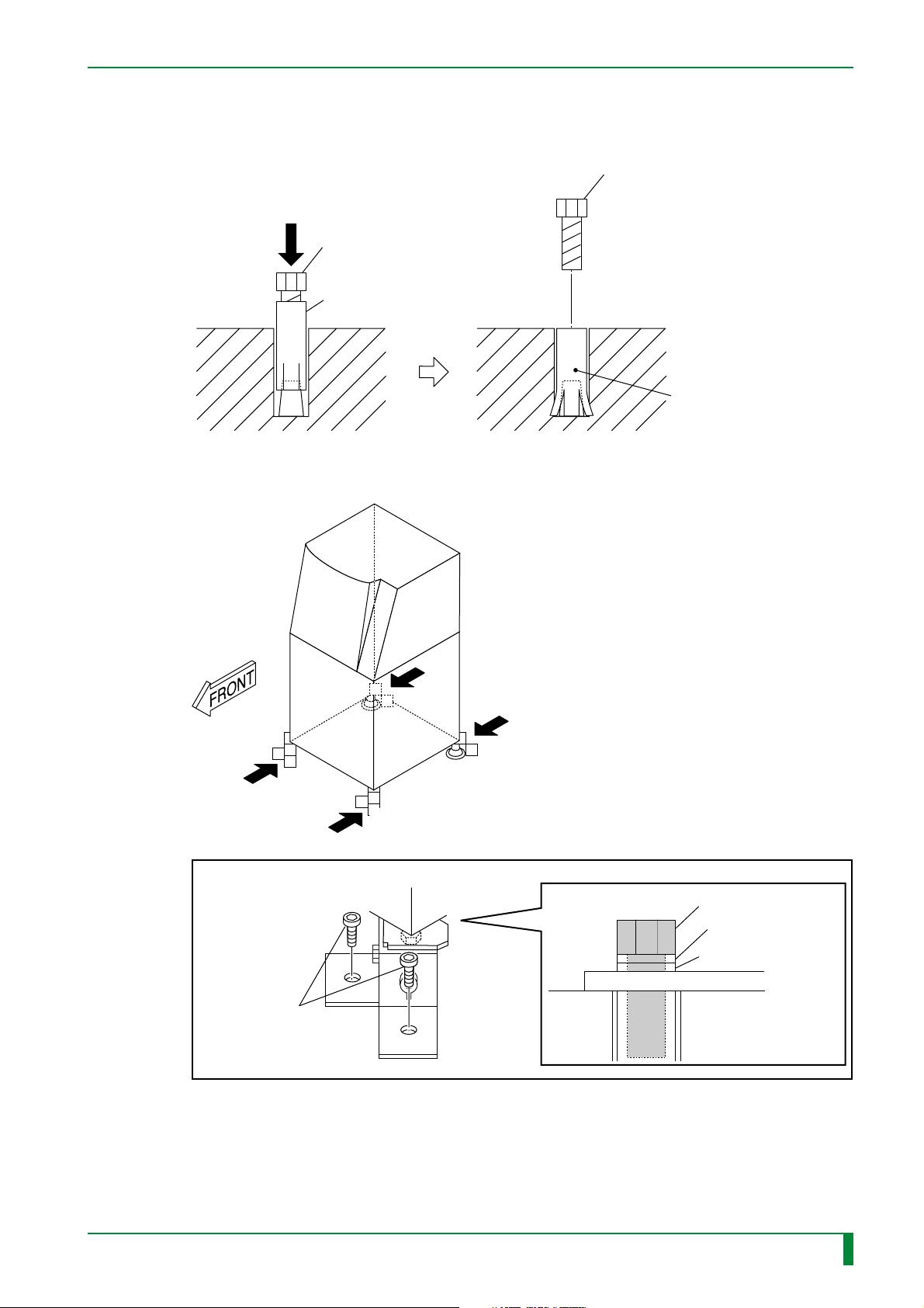
IN - 87
FR7H7208.EPS
A
A
DETAIL A
A
A
[Attach]
Hex head bolt
M12x25 (x2)
Hex head bolt M12x25
Spring washer M12
Plain washer M12
(3) Move the machine away for anchor nut embedding work.
(4) Drill holes at the locations marked for embedding the anchor nuts, and embed the
anchor nuts.
#3
#2
[Embed] Anchor nut
#1
[Attach] Embedding bolt
Anchor nut
M12x50
(5) Secure the machine in place.
[Remove] Embedding bolt
Anchor nut
FR7H7087.EPS
009-058-01
05.15.2001 FM3052
CR-IR347
Service Manual
IN - 87
 Loading...