


 Loading...
SERVICE MANUAL
CODE: 00ZMXB401/S1E
DIGITAL MULTIFUNCTIONAL
SYSTEM
MODEL MX-B401
CONTENTS
NOTE FOR SERVICING
[1] PRODUCT OUTLINE . . . . . . . . . . . . . . . . . . . . . . . . . . . . . . . . . . . . . . . . . . . . . . . 1-1 [2] CONSUMABLE PARTS . . . . . . . . . . . . . . . . . . . . . . . . . . . . . . . . . . . . . . . . . . . . . 2-1 [3] EXTERNAL VIEW AND INTERNAL STRUCTURE . . . . . . . . . . . . . . . . . . . . . . . . 3-1 [4] ADJUSTMENTS . . . . . . . . . . . . . . . . . . . . . . . . . . . . . . . . . . . . . . . . . . . . . . . . . . . 4-1 [5] SIMULATION . . . . . . . . . . . . . . . . . . . . . . . . . . . . . . . . . . . . . . . . . . . . . . . . . . . . . 5-1 [6] SELF DIAG AND TROUBLE CODE . . . . . . . . . . . . . . . . . . . . . . . . . . . . . . . . . . . . 6-1 [7] FIRMWARE UPDATE . . . . . . . . . . . . . . . . . . . . . . . . . . . . . . . . . . . . . . . . . . . . . . . 7-1 [8] OPERATIONAL DESCRIPTIONS. . . . . . . . . . . . . . . . . . . . . . . . . . . . . . . . . . . . . . 8-1 [9] MAINTENANCE . . . . . . . . . . . . . . . . . . . . . . . . . . . . . . . . . . . . . . . . . . . . . . . . . . . 9-1 [10] DISASSEMBLY AND ASSEMBLY . . . . . . . . . . . . . . . . . . . . . . . . . . . . . . . . . . . . 10-1 [11] VARIOUS STORAGE DATA HANDLING . . . . . . . . . . . . . . . . . . . . . . . . . . . . . . . 11-1 [12] SERVICE WEB PAGE . . . . . . . . . . . . . . . . . . . . . . . . . . . . . . . . . . . . . . . . . . . . . 12-1 [13] SPECIFICATIONS . . . . . . . . . . . . . . . . . . . . . . . . . . . . . . . . . . . . . . . . . . . . . . . . 13-1 [14] SIGNAL LIST . . . . . . . . . . . . . . . . . . . . . . . . . . . . . . . . . . . . . . . . . . . . . . . . . . . . 14-1 [15] ACTUAL WIRING DIAGRAM . . . . . . . . . . . . . . . . . . . . . . . . . . . . . . . . . . . . . . . . 15-1
Parts marked with "  " are important for maintaining the safety of the set. Be sure to replace these parts with specified ones for maintaining the safety and performance of the set.
This document has been published to be used SHARP CORPORATION for after sales service only.
The contents are subject to change without notice.
CONTENTS
NOTE FOR SERVICING
1. Precautions for servicing . . . . . . . . . . . . . . . . . . . . . . . . . i 2. Warning for servicing . . . . . . . . . . . . . . . . . . . . . . . . . . . . i 3. Note for installing site. . . . . . . . . . . . . . . . . . . . . . . . . . . . i 4. Note for handling PWB and electronic parts . . . . . . . . . .ii 5. Note for repairing/replacing the LSU . . . . . . . . . . . . . . . iii
6.Note for handling the drum cartridge, the transfer unit, the developer cartridge,
and the fusing unit . . . . . . . . . . . . . . . . . . . . . . . . . . . . . iii
[1]PRODUCT OUTLINE
1. System configuration . . . . . . . . . . . . . . . . . . . . . . . . . . 1-1 2. Machine configuration . . . . . . . . . . . . . . . . . . . . . . . . . 1-2 3. Option list . . . . . . . . . . . . . . . . . . . . . . . . . . . . . . . . . . . 1-2
[2]CONSUMABLE PARTS
1. Supply system table. . . . . . . . . . . . . . . . . . . . . . . . . . . 2-1 2. Maintenance parts list . . . . . . . . . . . . . . . . . . . . . . . . . 2-1 3. Production number identification . . . . . . . . . . . . . . . . . 2-2 4. Life end conditions . . . . . . . . . . . . . . . . . . . . . . . . . . . . 2-2 5. Life end display . . . . . . . . . . . . . . . . . . . . . . . . . . . . . . 2-3 6. Environment conditions . . . . . . . . . . . . . . . . . . . . . . . . 2-4
[3]EXTERNAL VIEW AND INTERNAL STRUCTURE
1. External view . . . . . . . . . . . . . . . . . . . . . . . . . . . . . . . . 3-1 2. Internal structure . . . . . . . . . . . . . . . . . . . . . . . . . . . . . 3-2 3. RSPF . . . . . . . . . . . . . . . . . . . . . . . . . . . . . . . . . . . . . . 3-3 4. Connectors. . . . . . . . . . . . . . . . . . . . . . . . . . . . . . . . . . 3-3 5. Operation panel . . . . . . . . . . . . . . . . . . . . . . . . . . . . . . 3-4 6. Sensors and detectors . . . . . . . . . . . . . . . . . . . . . . . . . 3-5 7. Switches. . . . . . . . . . . . . . . . . . . . . . . . . . . . . . . . . . . . 3-6 8. Clutches and solenoids . . . . . . . . . . . . . . . . . . . . . . . . 3-7 9. Drive motors. . . . . . . . . . . . . . . . . . . . . . . . . . . . . . . . . 3-8 10. Lamps . . . . . . . . . . . . . . . . . . . . . . . . . . . . . . . . . . . . . 3-9 11. Fans and filter . . . . . . . . . . . . . . . . . . . . . . . . . . . . . . 3-10 12. PWB. . . . . . . . . . . . . . . . . . . . . . . . . . . . . . . . . . . . . . 3-11 13. Fuses and Thermostats . . . . . . . . . . . . . . . . . . . . . . . 3-12 14. Gates . . . . . . . . . . . . . . . . . . . . . . . . . . . . . . . . . . . . . 3-13 15. Rollers . . . . . . . . . . . . . . . . . . . . . . . . . . . . . . . . . . . . 3-14
[4]ADJUSTMENTS
1. General . . . . . . . . . . . . . . . . . . . . . . . . . . . . . . . . . . . . 4-1 2. Adjustment item list . . . . . . . . . . . . . . . . . . . . . . . . . . . 4-1 3. Details of adjustment . . . . . . . . . . . . . . . . . . . . . . . . . . 4-2
[5]SIMULATION
1. General (Including basic operations) . . . . . . . . . . . . . . 5-1 2. List of simulation codes . . . . . . . . . . . . . . . . . . . . . . . . 5-3 3. Details of simulation. . . . . . . . . . . . . . . . . . . . . . . . . . . 5-7
[6]SELF DIAG AND TROUBLE CODE
1. Self diag . . . . . . . . . . . . . . . . . . . . . . . . . . . . . . . . . . . . 6-1 2. Trouble code list. . . . . . . . . . . . . . . . . . . . . . . . . . . . . . 6-4 3. Details of trouble code . . . . . . . . . . . . . . . . . . . . . . . . . 6-6
[7]FIRMWARE UPDATE
1. Outline . . . . . . . . . . . . . . . . . . . . . . . . . . . . . . . . . . . . . 7-1 2. Update procedure . . . . . . . . . . . . . . . . . . . . . . . . . . . . 7-1
[8]OPERATIONAL DESCRIPTIONS
1. Operation panel . . . . . . . . . . . . . . . . . . . . . . . . . . . . . . 8-1 2. Scanner section . . . . . . . . . . . . . . . . . . . . . . . . . . . . . . 8-2 3. Manual paper feed section. . . . . . . . . . . . . . . . . . . . . . 8-4 4. Paper feed tray section . . . . . . . . . . . . . . . . . . . . . . . . 8-6
5. Paper transport and switchback section . . . . . . . . . . . 8-9 6. LSU section . . . . . . . . . . . . . . . . . . . . . . . . . . . . . . . . 8-11 7. Photo-conductor section . . . . . . . . . . . . . . . . . . . . . . 8-14 8. Toner supply section . . . . . . . . . . . . . . . . . . . . . . . . . 8-18 9. Developing section. . . . . . . . . . . . . . . . . . . . . . . . . . . 8-19 10. Transfer section . . . . . . . . . . . . . . . . . . . . . . . . . . . . . 8-21 11. Fusing section . . . . . . . . . . . . . . . . . . . . . . . . . . . . . . 8-25 12. Paper exit section. . . . . . . . . . . . . . . . . . . . . . . . . . . . 8-28
13. Process control sensor,
image registration sensor section . . . . . . . . . . . . . . . 8-29 14. Automatic document feeder . . . . . . . . . . . . . . . . . . . . 8-30 15. Electrical section . . . . . . . . . . . . . . . . . . . . . . . . . . . . 8-32
[9]MAINTENANCE
1. Necessary work for maintenance. . . . . . . . . . . . . . . . . 9-1 2. Maintenance timing display . . . . . . . . . . . . . . . . . . . . . 9-1 3. Maintenance list . . . . . . . . . . . . . . . . . . . . . . . . . . . . . . 9-4
[10] DISASSEMBLY AND ASSEMBLY
1. External view . . . . . . . . . . . . . . . . . . . . . . . . . . . . . . . 10-1 2. Operation panel section . . . . . . . . . . . . . . . . . . . . . . .10-4 3. Scanner section . . . . . . . . . . . . . . . . . . . . . . . . . . . . . 10-7 4. Manual paper feed section. . . . . . . . . . . . . . . . . . . . . 10-9 5. Tray paper feed section . . . . . . . . . . . . . . . . . . . . . . 10-12 6. Paper transport, switchback section . . . . . . . . . . . . 10-15 7. LSU section . . . . . . . . . . . . . . . . . . . . . . . . . . . . . . . 10-18 8. OPC drum section . . . . . . . . . . . . . . . . . . . . . . . . . . 10-19 9. Toner supply section . . . . . . . . . . . . . . . . . . . . . . . . 10-21 10. Developing section. . . . . . . . . . . . . . . . . . . . . . . . . . 10-22 11. Transfer section . . . . . . . . . . . . . . . . . . . . . . . . . . . . 10-23 12. Fusing section . . . . . . . . . . . . . . . . . . . . . . . . . . . . . 10-28 13. Paper exit section. . . . . . . . . . . . . . . . . . . . . . . . . . . 10-35 14. Drive section . . . . . . . . . . . . . . . . . . . . . . . . . . . . . . 10-37 15. PWB . . . . . . . . . . . . . . . . . . . . . . . . . . . . . . . . . . . . . 10-44 16. Fan . . . . . . . . . . . . . . . . . . . . . . . . . . . . . . . . . . . . . . 10-49 17. Filter . . . . . . . . . . . . . . . . . . . . . . . . . . . . . . . . . . . . . 10-51 18. Process control sensor, registration sensor . . . . . . . 10-51 19. Document feed unit . . . . . . . . . . . . . . . . . . . . . . . . . 10-53 20. Other . . . . . . . . . . . . . . . . . . . . . . . . . . . . . . . . . . . . 10-56
[11] VARIOUS STORAGE DATA HANDLING |
|
1. Necessary works when replacing the PWB |
|
and the HDD . . . . . . . . . . . . . . . . . . . . . . . . . . . . . . . |
11-1 |
[12] SERVICE WEB PAGE
1. General . . . . . . . . . . . . . . . . . . . . . . . . . . . . . . . . . . .12-1 2. Details and operation procedures . . . . . . . . . . . . . . . 12-1
[13] SPECIFICATIONS
1. Basic specifications. . . . . . . . . . . . . . . . . . . . . . . . . . 13-1
[14]SIGNAL LIST
[15]ACTUAL WIRING DIAGRAM
1. Image process (MFPC, LSU) . . . . . . . . . . . . . . . . . . . 15-1 2. Scanner, Operation section (8.5) . . . . . . . . . . . . . . . . 15-2
3. Paper feed transport, Process drive, Front,
High voltage . . . . . . . . . . . . . . . . . . . . . . . . . . . . . . . . 15-3 4. Right door, Frame fusing . . . . . . . . . . . . . . . . . . . . . . 15-4 5. Process, DV, RESI, Paper exit. . . . . . . . . . . . . . . . . . 15-5 6. Power source, Frame electrical fitting, Option . . . . . . 15-6 7. AC, Fusing . . . . . . . . . . . . . . . . . . . . . . . . . . . . . . . . . 15-7
NOTE FOR SERVICING
1.Precautions for servicing
1)When servicing, disconnect the power plug, the printer cable, the network cable, and the telephone line from the machine, except when performing the communication test, etc.
It may cause an injury or an electric shock.
2)There is a high temperature area inside the machine. Use an extreme care when servicing.
It may cause a burn.
3)There is a high voltage section inside the machine which may cause an electric shock. Be careful when servicing.
4)Do not disassemble the laser unit. Do not insert a reflective material such as a screwdriver in the laser beam path.
It may damage eyes by reflection of laser beams.
5)When servicing with the machine operating, be careful not to squeeze you hands by the chain, the belt, the gear, and other driving sections.
6)Do not leave the machine with the cabinet disassembled.
Do not allow any person other than a serviceman to touch inside the machine. It may cause an electric shock, a burn, or an injury.
7)When servicing, do not breathe toner, developer, and ink excessively. Do not get them in the eyes.
If toner, developer, or ink enters your eyes, wash it away with water immediately, and consult a doctor if necessary.
8)The machine has got sharp edges inside. Be careful not to damage fingers when servicing.
9)Do not throw toner or a toner cartridge in a fire. Otherwise, toner may pop and burn you.
10)When replacing the lithium battery of the PWB, use a specified one only.
If a battery of different specification is used, it may be broken, causing breakdown or malfunction of the machine.
11)When carrying a unit with PWB or electronic parts installed to it, be sure to put it in an anti-static-electricity bag.
It may cause a breakdown or malfunctions.
CAUTION
DOUBLE POLE/NEUTRAL FUSING
(200V series only)
4)When connecting the grounding wire, never connect it to the following points.
It may cause an explosion, a fire or an electric shock.
•Gas tube
•Lightning conductor
•A water pipe or a water faucet, which is not recognized as a grounding object by the authorities.
•Grounding wire for telephone line
5)Do not damage, break, or work the power cord.
Do not put heavy objects on the power cable. Do not bend it forcibly or do not pull it extremely.
It may cause a fire or an electric shock.
6)Keep the power cable away from a heat source.
Do not insert the power plug with dust on it into a power outlet. It may cause a fire or an electric shock.
7)Do not put a receptacle with water in it or a metal piece which may drop inside the machine.
It may cause a fire or an electric shock.
8)With wet or oily hands, do not touch the power plug, do not insert the telephone line jack, do not operate the machine, or do not perform servicing.
It may cause an electric shock.
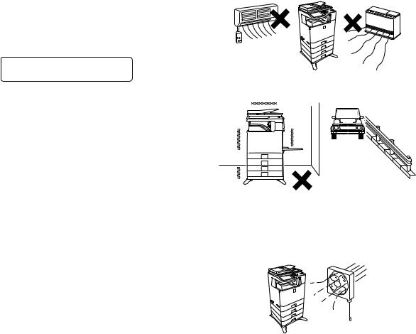
3. Note for installing site
Do not install the machine at the following sites.
1)Place of high temperature, high humidity, low temperature, low humidity, place under an extreme change in temperature and humidity.
Paper may get damp and form dews inside the machine, causing paper jam or copy dirt.
For operating and storing conditions, refer to the specifications described later.
2)Place of much vibrations
It may cause a breakdown.
2.Warning for servicing
1)Be sure to connect the power cord only to a power outlet that meets the specified voltage and current requirements.
Avoid complex wiring, which may lead to a fire or an electric shock.
It may cause a fire or an electric shock.
2)If there is any abnormality such as a smoke or an abnormal smell, interrupt the job and disconnect the power plug.
It may cause a fire or an electric shock.
3)Be sure to connect the grounding wire. If an electric leakage occurs without grounding, a fire or an electric shock may result.
To protect the machine and the power unit from lightening, grounding must be made.
3)Poorly ventilated place
An electrostatic type copier will produce ozone inside it.
The quantity of ozone produced is designed to a low level so as not to affect human bodies. However, continuous use of such a machine may produce a smell of ozone. Install the machine in a well ventilated place, and ventilate occasionally.
MX-B401 NOTE FOR SERVICING - i
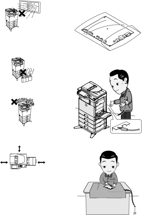
4)Place of direct sunlight.
Plastic parts and ink may be deformed, discolored, or may undergo qualitative change.
It may cause a breakdown or copy dirt.
5)Place which is full of organic gases such as ammonium
The organic photo-conductor (OPC) drum used in the machine may undergo qualitative change due to organic gases such as ammonium.
Installation of this machine near a diazo-type copier may result in dirt copy.
6)Place of much dust
When dusts enter the machine, it may cause a breakdown or copy dirt.
7)Place near a wall
Some machine require intake and exhaust of air.
If intake and exhaust of air are not properly performed, copy dirt or a breakdown may be resulted.
|
11-13/16" |
|
(30cm) |
11-13/16" |
17-23/32" |
(30cm) |
(45cm) |
8)Unstable or slant surface
If the machine drops or fall down, it may cause an injury or a breakdown.
If there are optional paper desk and the copier desk specified, it is recommendable to use them.
When using the optional desk, be sure to fix the adjuster and lock the casters.
4.Note for handling PWB and electronic parts
When handling the PWB and the electronic parts, be sure to observe the following precautions in order to prevent against damage by static electricity.
1)When in transit or storing, put the parts in an anti-static bag or an anti-static case and do not touch them with bare hands.
2)When and after removing the parts from an anti-static bag (case), use an earth band as shown below:
•Put an earth band to your arm, and connect it to the machine.
•When repairing or replacing an electronic part, perform the procedure on an anti-static mat.
MX-B401 NOTE FOR SERVICING - ii
5.Note for repairing/replacing the LSU
When repairing or replacing, be sure to observe the following items.
1)When repairing or replacing the LSU, be sure to disconnect the power plug from the power outlet.
2)When repairing or replacing the LSU, follow the procedures described in this Service Manual.
3)When checking the operations after repairing the LSU, keep all the parts including the cover installed and perform the operation check.
4)Do not modify the LSU.
5)When visually checking the inside of the machine for the operation check, be careful not to allow laser beams to enter the eyes.
If the above precaution is neglected or an undesignated work is performed, safety may not be assured.
6.Note for handling the drum cartridge, the transfer unit, the developer cartridge, and the fusing unit
When handling the OPC drum unit, the transfer unit, and the developer unit, strictly observe the following items.
If these items are neglected, a trouble may be generated in the copy and print image quality.
(Drum cartridge)
1)Avoid working at a place with strong lights.
2)Do not expose the OPC drum to lights including interior lights for a long time.
3)When the OPC drum is removed from the machine, cover it with light blocking material. (When using paper, use about 10 sheets of paper to cover it.)
4)Be careful not to attach fingerprints, oil, grease, or other foreign material on the OPC drum surface.
(Transfer unit)
1)Be careful not to attach fingerprints, oil, grease, or other foreign material on the transfer belt and the transfer roller.
(Developer cartridge)
1)Be careful not to attach fingerprints, oil, grease, or other foreign material on the developer unit.
(Fusing unit)
1)Be careful not to put fingerprints, oil, grease, or other foreign material on the fusing roller and the external heating belt.
2)Do not leave the fusing roller in contact state for a long time.
MX-B401 NOTE FOR SERVICING - iii
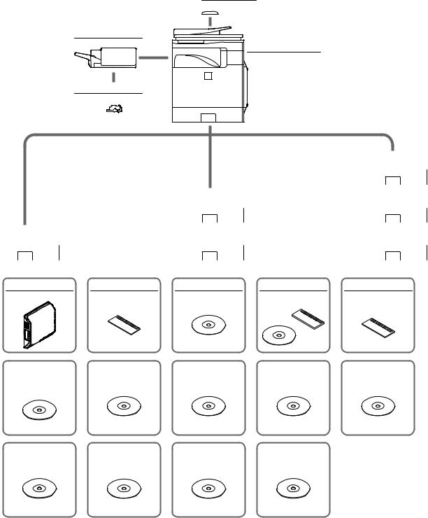
[1] PRODUCT OUTLINE
1. System configuration
MX-BTX1
Business card feeder
MX-FN12
Finisher
MX-B401
Digital multifunctional system
MX-SCX1
Staple cartridge
|
|
|
|
|
|
MX-CSX1 |
|
|
|
|
|
|
|
500-sheet paper feed unit |
|
|
|
|
|
|
|
|
|
|
|
|
|
|
|
|
|
|
|
|
MX-CSX1 |
|
|
MX-CSX2 |
|
|
|
|
500-sheet paper feed unit |
|
|
500-sheet paper feed unit |
|
MX-CSX1 |
|
|
|
|
|
|
|
|
|
|
|
|
|
|
|
|
|
MX-CSX2 |
|
|
MX-CSX2 |
|
|
500-sheet paper feed unit |
|
|
500-sheet paper feed unit |
|
|
500-sheet paper feed unit |
|
|
|
|
|
|
|
|
|
|
|
|
|
|
|
|
|
MX-FXX3 |
MX-SMX3 |
MX-FWX1 |
AR-PF1 |
MX-FR16U |
Facsimile expansion kit |
Expansion memory board |
Internet fax expansion kit |
Bar code font kit |
Data security kit |
|
|
|
|
(Commercial version) |
MX-AMX1 |
|
MX-AMX2 |
MX-AMX3 |
MX-USX1 |
MX-USX5 |
|||
|
|
|
|
|
|
|
|
|
Application integration |
|
Application communication |
External account module |
Sharpdesk 1 license kit |
Sharpdesk 5 license kit |
|||
module |
|
module |
|
|
|
|
|
|
MX-US10 |
MX-US50 |
|
MX-USA0 |
MX-PUX1 |
||
Sharpdesk 10 license kit |
|
|
|
|
|
XPS expansion kit |
Sharpdesk 50 license kit |
|
Sharpdesk 100 license kit |
||||
MX-B401 PRODUCT OUTLINE 1 – 1
2. |
Machine configuration |
|
|
|
|
|
|
|
|
|
|
|
|
|
|
|
|
|
MX-B401 |
|
|
|
|
Main body LCD |
|
CL 8.5 |
|
|
|
|
|
RSPF |
|
STD |
|
|
|
|
|
Automatic duplex |
|
STD |
|
|
|
|
|
HDD |
|
|
STD |
|
|
|
|
System memory (For Program, Printer) |
512MB |
|
|
|
|
||
Local memory (Copier) |
|
512MB |
|
|
|
|
|
Copier |
|
STD |
|
|
|
|
|
GDI printer |
|
– |
|
|
|
|
|
SPDL/PCL printer |
|
STD |
|
|
|
|
|
PS printer |
|
STD |
|
|
|
|
|
EFI printer |
|
– |
|
|
|
|
|
FAX |
|
|
OPT |
|
|
|
|
Internet Fax |
|
OPT *1 |
|
|
|
|
|
Network scanner |
|
STD |
|
|
|
|
|
Filing |
|
STD |
|
|
|
|
|
Security |
|
OPT *1 |
|
|
|
|
|
OSA |
|
|
Expansion enable |
|
|
|
|
STD: Standard provision, |
OPT: Option, |
–: No setting |
|
|
|
||
*1: Product key target |
|
|
|
|
|
|
|
3. |
Option list |
|
|
|
|
|
|
|
|
|
|
|
|
|
|
|
Model |
|
Name |
Model name |
MX-B401 |
Product key target |
|
Paper feed system |
|
500-sheet paper feed unit |
MX-CSX1 |
OPT |
– |
||
|
|
|
500-sheet paper feed unit |
MX-CSX2 |
OPT |
– |
|
|
|
|
Business card feeder |
MX-BTX1 |
OPT |
– |
|
Paper exit system |
|
Finisher |
MX-FN12 |
OPT |
– |
||
Electrical system (ROM) |
|
Bar code font kit |
AR-PF1 |
OPT |
– |
||
|
|
|
Data security kit |
MX-FR16U |
OPT |
Yes |
|
Electrical system (Software) |
|
Internet fax expansion kit |
MX-FWX1 |
OPT |
Yes |
||
|
|
|
XPS expansion kit |
MX-PUX1 |
OPT *1 |
Yes |
|
|
|
|
Sharpdesk 1 license kit |
MX-USX1 |
OPT |
– |
|
|
|
|
Sharpdesk 5 license kit |
MX-USX5 |
OPT |
– |
|
|
|
|
Sharpdesk 10 license kit |
MX-US10 |
OPT |
– |
|
|
|
|
Sharpdesk 50 license kit |
MX-US50 |
OPT |
– |
|
|
|
|
Sharpdesk 100 license kit |
MX-USA0 |
OPT |
– |
|
|
|
|
Application integration module |
MX-AMX1 |
OPT |
Yes |
|
|
|
|
Application communication module |
MX-AMX2 |
OPT |
Yes |
|
|
|
|
External account module |
MX-AMX3 |
OPT |
Yes |
|
|
|
|
Facsimile expansion kit |
MX-FXX3 |
OPT |
– |
|
Memory |
|
Expansion memory board |
MX-SMX3 |
OPT |
– |
||
STD: Standard provision, |
OPT: Option, |
–: No setting |
|
|
|
||
*1: To install the MX-PUX1, the MX-SMX3 is required.
MX-B401 PRODUCT OUTLINE 1 – 2
[2] CONSUMABLE PARTS
1. Supply system table
A. USA/Canada/South and Central America
No. |
Item |
Content |
|
Life |
Model Name |
Quantity in |
Remarks |
|
collective package |
||||||
|
|
|
|
|
|
|
|
1 |
Toner Cartridge |
Toner Cartridge with IC Chip |
x 1 |
10K *1 |
MX-B40NT1 |
10 |
|
|
|
(Toner : Net 215g) |
|
|
|
|
|
2 |
Developer Cartridge |
Developer Cartridge |
x 1 |
72K *2 |
MX-C40NVB |
10 |
|
|
|
(Developer : Net 185g) |
|
|
|
|
|
3 |
Drum Cartridge |
Drum Cartridge |
x 1 |
72K *2 |
MX-C40NRB |
10 |
|
|
|
Charger Cleaner |
x 1 |
|
|
|
|
*1: Life: A4/Letter size at Area Coverage 5% (Reference: 8K for A4/Letter 6%)
The toner life may vary depending on the document density and temperature and humidity. *2: 72K sheets or 550K rotations (For details, refer to item 4, "Life end conditions.")
The life of the above Developer Cartridge and the Drum Cartridge is 72K only when they are installed to the MX-B401.
2. Maintenance parts list
A. USA/Canada/South and Central America
No. |
Item |
Model name |
Content |
Quantity |
Life |
Package |
Remarks |
1 |
Heat roller kit |
MX-C31HK |
Upper heat roller assembly |
1 |
120K |
5 |
|
|
|
|
Lower heat roller assembly |
1 |
|
|
|
|
|
|
External heating unit |
1 |
|
|
|
|
|
|
Separation pawl lower |
2 |
|
|
|
|
|
|
Separation pawl lower spring |
2 |
|
|
|
|
|
|
Upper thermistor retainer |
1 |
|
|
|
|
|
|
Upper thermistor |
1 |
|
|
|
|
|
|
Lower thermistor |
1 |
|
|
|
2 |
Primary transfer kit |
MX-B40Y1 |
Intermediate transfer belt F |
1 |
120K |
5 |
|
|
|
|
Primary transfer roller F |
1 |
|
|
|
|
|
|
Cleaning blade |
1 |
|
|
|
|
|
|
PTC wire |
1 |
|
|
|
|
|
|
PTC cleaner assembly |
1 |
|
|
|
|
|
|
PTC cleaner B AS |
1 |
|
|
|
|
|
|
Primary transfer drive coupling |
1 |
|
|
|
3 |
Primary transfer belt unit |
MX-B40U1 |
Primary transfer belt unit |
1 |
120K |
1 |
|
4 |
Secondary transfer roller unit |
MX-C31U2 |
Secondary transfer roller unit |
1 |
60K |
1 |
|
5-1 |
Fusing unit |
MX-C31FU1 |
Fusing unit (Heater lamp 120V) |
1 |
120K |
1 |
|
|
|
|
Ozone filter |
1 |
|
|
|
5-2 |
Fusing unit |
MX-C31FU |
Fusing unit (Heater lamp 230V) |
1 |
120K |
1 |
|
|
|
|
Ozone filter |
1 |
|
|
|
6 |
Filter kit |
MX-C31FL |
Ozone filter |
1 |
120K |
10 |
|
7 |
Toner collection container |
MX-B40HB |
Toner collection container |
2 |
45K for |
5 |
|
|
|
|
LSU cleaner |
2 |
one *1 |
|
|
8 |
Paper feed roller kit |
MX-C31RT |
Paper feed roller FT |
1 |
Replace |
10 |
Reference: About 100K |
|
|
|
Take-up roller FT |
1 |
as needed. |
|
(Commonly used for the |
|
|
|
Separation roller FT |
1 |
|
|
MX-CSX1/MX-CSX2.) |
9 |
Manual paper feed roller kit |
MX-C31MR |
MF paper feed roller |
1 |
Replace |
10 |
Reference: About 100K |
|
|
|
Manual paper feed separation pad unit |
1 |
as needed. |
|
|
10 |
DF roller kit |
MX-C31DF |
Pickup_assembly |
1 |
Replace |
10 |
Reference: About 100K |
|
|
|
Pad_separation_assembly |
1 |
as needed. |
|
|
11 |
Staple cartridge |
MX-SCX1 |
Staple cartridge |
3 |
5000 times |
20 |
Consumable part of the |
|
|
|
|
|
x 3 |
|
MX-FN12 (option) |
*1: The life is estimated with 5% coverage. It differs depending on the use conditions of the machine.
MX-B401 CONSUMABLE PARTS 2 – 1
3. Production number identification
A. Developer cartridge
: Unit code/Model name  : Color code
 : Destination
 : Skating
 : Production place
{: Production date (YYYYMMDD)  : Serial number
 : Version number
B. Toner cartridge
The indications of a lot number are the same as those of the developer cartridge.
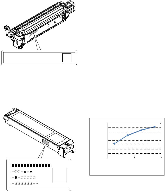
4. Life end conditions
A. Toner cartridge
After detecting near end, when the toner density is lowered to the specified level or lower and the toner sensor detects toner LOW continuously for a certain time, it is judged as toner end.
B. Developer cartridge/Drum cartridge
•When the developer (developer cartridge)/drum counter exceeds the specified number of sheets.
•When the rpm of the developer cartridge/drum cartridge exceeds the specified number.
In an actual use, in the correction operation and the warm-up operation as well as the output operation, the developer cartridge and the drum rotate idly.
If the correction operation and the warm-up operation are made frequently, idle rotations of the developer cartridge and the drum are increased accordingly.
Because of these factors, the consumption degree of the developer cartridge and the drum cartridge cannot be determined only with the print quantity. When, therefore, the number of rotations of the cartridge exceeds the specified level, it is judged as life end.
|
Developer (Developer |
Number of rotations |
|
of Developer |
|
|
cartridge)/ |
|
|
(Developer cartridge)/ |
|
|
Drum counter |
|
|
Drum |
|
|
|
|
|
Black-White |
Black-White |
Developer (Developer |
72K |
550K rotations |
cartridge)/Drum |
|
|
As the reference for the drum/developer (developer cartridge) life. the accumulated number of rotations can be displayed with SIM 22- 1. The value displayed with SIM 22-1 indicates the reached level in percent (%) when the developer (developer cartridge)/drum life is 100%.
Example) Life 550K, used number of rotations 385K 385/550 x 100 = 70 (%)
|
80,000 |
|
|
|
|
quantity |
70,000 |
|
50,000 |
|
|
printable |
60,000 |
|
40,000 |
|
|
|
|
|
|
30,000 |
|
of |
20,000 |
|
Numbers |
10,000 |
|
|
|
|
|
0 |
|
|
|
Single |
multi |
sheets |
multi |
sheets |
multi |
|
sheets |
multi |
2 |
3 |
|
4 |
|
||||
|
|
|
|
|
|
Single multi |
33,000 |
2 sheets multi |
52,000 |
3 sheets multi |
64,000 |
4 sheets multi |
72,000 |
MX-B401 CONSUMABLE PARTS 2 – 2
5. Life end display
A. Drum cartridge
|
|
Display condition |
|
Print job |
Display content |
Sim26-38-E |
Counter name |
Counter value |
Enable/ |
|
set value |
Disable |
||
|
|
|
||
Change the supplies. > Drum Cartridge |
0 (Print continue) |
Drum cartridge print counter |
When 72K is reached |
Enable |
|
|
Drum cartridge accumulated rotation number |
When 550K rotations is reached |
Enable |
The supplies will be needed soon. |
1 (Print stop) |
Drum cartridge print counter |
When 90% of 72K is reached by the |
Enable |
> Drum Cartridge *1 |
|
|
counter |
|
|
|
Drum cartridge accumulated rotation number |
When 90% of 550K rotation is |
Enable |
|
|
|
reached by the counter |
|
Change the supplies. > Drum Cartridge |
1 (Print stop) |
Drum cartridge print counter |
When 72K is reached |
Enable |
|
|
|
When 72K + 1K is reached |
Disable |
|
|
Drum cartridge accumulated rotation number |
When 550K rotations is reached |
Enable |
|
|
|
When 550K rotation + 430Kmm is |
Disable |
|
|
|
reached |
|
*1: Selection of Display/Not Display can be made with Sim26-69. (Default: Not Display)
•When the drum cartridge is replaced with a new one, the print counter, the accumulated traveling distance counter, the accumulated rotation number counter, and the usage day counter are automatically cleared. If SIM26-55 setting is set to ENABLE in that case, the guidance for execution of the automatic adjustment of the engine is displayed.
•If SIM26-55 setting is set to DISABLE, SIM46-74 must be used to execute the automatic adjustment of the engine.
•If the above guidance does not disappear when the drum cartridge is replaced, SIM24-7 must be executed to clear the print counter, the accumulated traveling distance counter, the accumulated rotation number counter, and the usage day counter, and the engine automatic adjustment must be executed.
•The above display disappears when the counters are cleared.
B. Developer cartridge
|
|
Display condition |
|
Print job |
Display content |
Sim26-38-F |
Counter name |
Counter value |
Enable/ |
|
set value |
Disable |
||
|
|
|
||
Change the supplies. |
0 (Print continue) |
Developer cartridge print counter |
When 72K is reached |
Enable |
> Developer Cartridge |
|
Developer cartridge accumulated rotation number |
When 550K rotations is reached |
Enable |
The supplies will be needed soon. |
1 (Print stop) |
Developer cartridge print counter |
When 90% of 60K is reached by the |
Enable |
> Developer Cartridge *1 |
|
|
counter |
|
|
|
Developer cartridge accumulated rotation number |
When 90% of 550K rotation is |
Enable |
|
|
|
reached by the counter |
|
Change the supplies. |
1 (Print stop) |
Developer cartridge print counter |
When 72K is reached |
Enable |
> Developer Cartridge |
|
|
When 72K + 1K is reached |
Disable |
|
|
Developer cartridge accumulated rotation number |
When 550K rotations is reached |
Enable |
|
|
|
When 550K rotation + 430Kmm is |
Disable |
|
|
|
reached |
|
*1: Selection of Display/Not Display can be made with Sim26-69. (Default: Not Display)
•When the developer cartridge is replaced with a new one, the print counter, the accumulated traveling distance counter, the accumulated rotation number counter, and the usage day counter are automatically cleared, and the initial setting of the toner density is automatically executed.
•When SIM26-55 setting is set to ENABLE, the initial setting of the toner density is executed and the guidance for execution of the automatic adjustment of the engine is displayed.
•When SIM26-55 setting is set to DISABLE, SIM46-74 must be used to execute the automatic adjustment of the engine after completion of the initial setting of the toner density.
•If the above guidance does not disappear when the developer cartridge is replaced, the initial setting of the toner density must be executed with the simulation, and the engine automatic adjustment must be executed.
•When the initial setting of the toner density is executed, the counters are cleared and the above display disappears.
MX-B401 CONSUMABLE PARTS 2 – 3
C. Toner cartridge
|
|
Display condition |
Print job |
Display content |
Remaining |
Status |
Enable/ |
|
quantity display *1 |
Disable |
|
|
|
||
The supplies will be needed soon. > Toner Cartridge *2 |
25-0% |
Toner remaining quantity is 25% or less. |
Enable |
|
25-0% |
Toner remaining quantity corresponds to output of XX sheets. *3 |
Enable |
Change the supplies. > Toner Cartridge |
0% |
When the toner cartridge reaches toner end. |
Disable |
No display |
50-25% |
Toner remaining quantity is 49 - 25%. |
Enable |
No display |
75-50% |
Toner remaining quantity is 74 - 50%. |
Enable |
No display |
100-75% |
Toner remaining quantity is 100 -75%. |
Enable |
Install the toner cartridge. |
No display |
When no toner cartridges are installed. |
Disable |
Improper cartridge. |
No display |
When an incompatible toner cartridge is installed. |
Disable |
Cartridge error. |
No display |
CRUM trouble |
Disable |
|
|
Toner cartridge connector contact trouble |
|
*1: Detected by the toner motor rotation number and the pixel count (The value of larger life percentage is employed.) *2: Selection of Display/Not Display can be made with Sim26-69. (Default: Not Display)
*3: Setting can be made with Sim26-69. (Default: 0 sheet)
6. Environment conditions
A. Operating environment conditions
Temperature: 10 - 35°C |
Humidity: 20 - 85% RH |
Atmospheric pressure: 590 - 1013hPa (Altitude: 0 - 2000m) |
Humidity (RH) |
85% |
60% |
20% |
Temperature
B.Transit environment conditions (term: 2 weeks)
-20 - 45°C (Free from dew)
C. Storage environment conditions (unopened)
-10 - 40°C (Free from dew)
D. Disposal standard
Toner cartridge/developer cartridge: 24 months (unopened) from the production month.
Drum cartridge: 36 months from the production month
MX-B401 CONSUMABLE PARTS 2 – 4
[3] EXTERNAL VIEW AND INTERNAL STRUCTURE
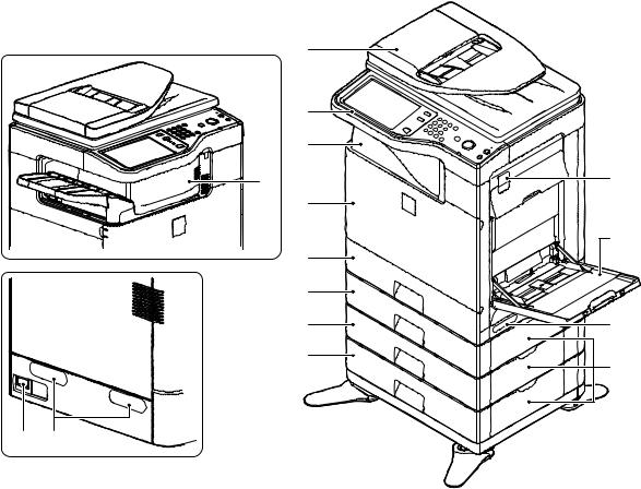
1. External view
1 |
|
2 |
|
3 |
|
4 |
12 |
|
|
5 |
|
|
13 |
6 |
|
7 |
|
8 |
11 |
9 |
14 |
|
10 11
No. |
Name |
Function/Operation |
1 |
Auto document feeder |
Feeds the set documents automatically, and scans them continuously. The duplex surfaces are scanned. |
2 |
Operation panel |
Used to enter an input of various settings or the copy quantity. |
3 |
Paper exit tray (Center tray) |
Copied or printed paper is discharged to this tray. |
4 |
Finisher *1 |
Delivers stapled paper, and allows offset discharge of paper. |
5 |
Front cover |
This is opened when replacing toner cartridges or the waste toner box. |
6 |
Tray 1 |
Stores paper. Max. 500 sheets (80g/m2, 21lbs) |
7 |
Tray 2 (with the MX-CSX1 installed) *1 |
Stores paper. Max. 500 sheets (80g/m2, 21lbs) |
8 |
Tray 3 (with the MX-CSX2 installed) *1 |
Stores paper. Max. 500 sheets (80g/m2, 21lbs) |
9 |
Tray 4 (with the MX-CSX2 installed) *1 |
Stores paper. Max. 500 sheets (80g/m2, 21lbs) |
10 |
Main power switch |
Turns on the power of the machine. When FAX or Internet FAX is used, keep it ON. |
11 |
Handle |
Use this handle to lift the main unit for transit. |
12 |
Right side cover release lever |
To remove paper jam, lift this lever and open the right side cover. |
13 |
Manual paper feed tray |
For manual paper feed, paper is inserted from this tray. When A4R or 8-1/2" x 11"R paper is set, extend the |
|
|
auxiliary tray. |
14 |
One-stage paper feed unit side cover |
To remove paper jam in tray 2, 3, or 4, open this cover. |
|
(with the MX-CSX1/2 installed) |
|
*1: Option
MX-B401 EXTERNAL VIEW AND INTERNAL STRUCTURE 3 – 1
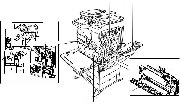
2. Internal structure
1 |
6 |
7 |
8 |
4 |
2 |
|
11 |
5 |
11 |
|
|
|
3 |
910
No. |
Name |
Function/Operation |
Note |
1 |
Toner cartridge |
When toner is exhausted in a cartridge, remove the cartridge and replace it |
|
|
|
with a new one. |
|
2 |
Drum cartridge |
This cartridge stores a drum. When the specified life is reached, replace it |
|
|
|
with a new cartridge. |
|
3 |
Developer cartridge |
This cartridge stores developer. When the specified life is reached, replace it |
|
|
|
with a new cartridge. |
|
4 |
MC cleaning rod insertion port |
When the copy quality is degraded by dirt on the MC unit, the rod to clean the |
|
|
|
MC unit is inserted into this port. |
|
5 |
LSU cleaning rod insertion port |
When the copy quality is degraded by dirt on the LSU, the rod to clean the |
|
|
|
LSU is inserted into this port. |
|
6 |
Fusing section |
Fuses images transferred on paper by heat. |
Note: The fusing section is heated |
|
|
|
to a high temperature. Be careful |
|
|
|
not to burn when paper jam. |
7 |
Transfer belt |
The transfer belt transfers toner on the drum. |
Do not touch or scratch. It may |
|
|
|
cause degraded images. |
8 |
Right side cover |
Opened when a paper jam is generated. |
|
9 |
Waste toner box |
Receives waste toner when copying or printing. |
The waste toner box is collected |
|
|
|
by the servicemen. |
10 |
Waste toner box release lever |
When the waste toner box is removed, this lever is rotated to release lock. |
|
11 |
Drum positioning plate unit release |
Releases lock of the drum positioning plate unit. When a drum cartridge or a |
|
|
lever |
developer cartridge is replaced, rotate this lever to open the drum positioning |
|
|
|
plate unit. |
|
MX-B401 EXTERNAL VIEW AND INTERNAL STRUCTURE 3 – 2
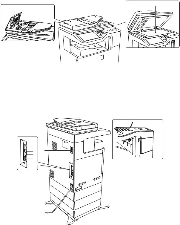
3. RSPF
6 7
1 |
2 |
3 |
4 |
5 |
|||||
|
|
|
|
|
|
|
|
|
|
|
|
|
|
|
|
|
|
|
|
|
|
|
|
|
|
|
|
|
|
|
|
|
|
|
|
|
|
|
|
|
|
|
|
|
|
|
|
|
|
No. |
Name |
Function/ Operation |
1 |
Document feed roller |
Transports a document automatically. |
2 |
Document feed section cover |
This cover is opened when removing a paper jam or cleaning the document feed roller. |
3 |
Document guide |
Guides to scan a document properly. Set to the set document size. |
4 |
Document set table |
A document is set on this table. In the case of a single-surface document, set it face up. |
5 |
Document exit section |
The scanned document is discharged to this section. |
6 |
Document scan section |
The document set on the document set table is scanned in this section. |
7 |
Document table (Glass surface) |
Used for thick documents or book documents which cannot be entered to the auto document feeder. |
4. Connectors
6
1 |
|
2 |
5 |
3 |
|
4 |
|
No. |
Name |
Function/ Operation |
1 |
USB connector (Type A) |
Used to connect a USB hub or USB memory. This connector cannot be used when shipping from the factory. |
2 |
LAN connector |
Used to connect a LAN cable to use this machine in a network. |
3 |
USB connector (Type B) |
Used to connect a computer to use this machine as a printer. |
4 |
Connector |
This connector is used by the serviceman. |
5 |
Inner finisher connection connector |
This connector is used to connect the inner finisher and the main unit when the inner finisher (option) is installed. |
6 |
USB connector (Type A) |
Used to connect a USB hub or USB memory. |
MX-B401 EXTERNAL VIEW AND INTERNAL STRUCTURE 3 – 3
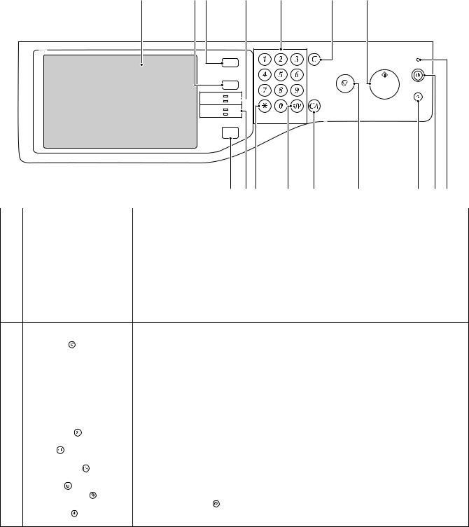
5. Operation panel
1 |
2 |
3 |
4 |
5 |
6 |
9 |
JOB STATUS
SYSTEM
SETTINGS
READY
PRINT DATA 
IMAGE SEND |
LINE |
|
|
DATA |
LOGOUT |
||
|
|||
|
HOME |
|
|
|
7 |
8 10 |
11 |
12 |
13 |
14 |
15 16 |
|
|
|
|
|
|
|
|
|
No. |
Name |
|
|
Function/Operation |
|
|
|
|
1 |
Touch panel |
Messages and keys appear in the touch panel display. |
|
|
|
|
||
|
|
Touch the displayed keys to perform a variety of operations. |
|
|
|
|
||
|
|
When a key is touched, a beep sounds and the selected item is highlighted. This provides confirmation as you |
||||||
|
|
perform an operation. |
|
|
|
|
|
|
2 |
[SYSTEM SETTINGS] key |
Press this key to display the system settings menu screen. The system settings are used to configure paper tray |
||||||
|
|
settings, store addresses for transmission operations, and adjust parameters to make the machine easier to use. |
||||||
3 |
[JOB STATUS] key |
Press this key to display the job status screen. The job status screen is used to check information on jobs and to |
||||||
|
|
cancel jobs. |
|
|
|
|
|
|
4 |
PRINT mode indicators |
• READY indicator |
|
|
|
|
|
|
|
|
Print jobs can be received when this indicator is lit. |
|
|
|
|
||
•DATA indicator
This blinks while print data is being received and lights steadily while printing is taking place.
5 |
Numeric keys |
|
|
These are used to enter the number of copies, fax numbers, and other numerical values. These keys are also used |
||
|
|
|
|
|
to enter numeric value settings (except for the system settings). |
|
6 |
[CLEAR] key ( |
) |
|
Press this key to return the number of copies to "0". |
||
7 |
[HOME] key |
|
|
|
Touch this key to display the home screen. Frequently used settings can be registered in the home screen to |
|
|
|
|
|
|
enable quick and easy operation of the machine. |
|
8 |
IMAGE SEND mode indicators |
• |
LINE indicator |
|||
|
|
|
|
|
|
This lights up during transmission or reception of a fax or Internet fax. This also lights during transmission of an |
|
|
|
|
|
|
image in scan mode. |
|
|
|
|
|
• |
DATA indicator |
|
|
|
|
|
|
This blinks when a received fax or Internet fax cannot be printed because of a problem such as out of paper. |
|
|
|
|
|
|
This lights up when there is a transmission job that has not been sent. |
9 |
[START] key |
|
|
|
Press this key to copy or scan an original. This key is also used to send a fax in fax mode. |
|
10 |
[LOGOUT] key ( |
) |
|
Press this key to log out after you have logged in and used the machine. When using the fax function, this key can |
||
|
|
|
|
|
also be pressed to send tone signals on a pulse dial line. |
|
11 |
[#/P] key ( |
) |
|
|
When using the copy function, press this key to use a job program. When using the fax function, this key can be |
|
|
|
|
|
|
used when dialing. |
|
12 |
[CLEAR ALL] key ( |
) |
Press this key to return to the initial operation state. |
|||
|
|
|
|
|
Use this key when you wish to cancel all settings that have been selected and start operation from the initial state. |
|
13 |
[STOP] key ( |
) |
|
|
Press this key to stop a copy job or scanning of an original. |
|
14 |
[POWER SAVE] key ( |
) / indicator |
Use this key to put the machine into auto power shut-off mode to save energy. |
|||
|
|
|
|
|
The [POWER SAVE] key ( ) blinks when the machine is in auto power shut-off mode. |
|
15 |
[POWER] key ( |
) |
|
Use this key to turn the machine power on and off. |
||
16 |
Main power indicator |
|
This lights up when the machine's main power switch is in the "on" position. |
|||
MX-B401 EXTERNAL VIEW AND INTERNAL STRUCTURE 3 – 4

6. Sensors and detectors
|
SCOV |
SPPD1 |
SPED |
|
|
SOCD |
SPPD2 |
|
MHPS |
TFD2 |
|
POD2
POD1
|
|
|
RTH_EX1 |
|
APPD1 |
|
|
|
|
RTH_EX2 |
HLPCD |
|
|||
|
|
RTH_Sub |
|
|
|||
|
|
|
|
|
|
|
|
|
|
1TUD_K |
RTH_Main |
RTH_Low |
|
||
|
1TUD_CL |
|
REGS_R |
|
|
||
|
|
|
|
|
|
||
|
|
TCS_K |
PPD2 |
APPD2 |
|
|
|
|
|
|
|
|
|||
|
|
|
|
|
|
|
MPLD1 |
|
|
|
|
PPD1 |
MPWS |
|
|
|
|
|
|
MPED |
|
||
|
|
|
|
CPED1 CPFD1 |
|
||
|
|
|
|
CLUD1 |
|
|
|
|
|
|
|
|
TH/HUD |
|
|
|
|
CSPD1 |
|
|
|
|
|
Signal name |
Name |
Type |
|
|
Function/Operation |
Note |
|
1TUD_CL |
Transfer belt separation detector CL |
Transmission type |
Detects separation of the transfer belt. |
High voltage PWB |
|||
|
|
|
|
|
|
|
holder unit |
1TUD_K |
Transfer belt separation detector BK |
Transmission type |
Detects initialization of the primary transfer unit. |
Frame unit |
|||
APPD1 |
ADU transport path detector 1 |
Transmission type |
Detects paper pass in the upper stream of the |
Right door unit |
|||
|
|
|
switchback section. |
|
|
||
APPD2 |
ADU transport path detector 2 |
Transmission type |
Detects paper pass in the middle stream of the |
Right door unit |
|||
|
|
|
switchback section. |
|
|
||
CLUD1 |
Tray 1 upper limit detector |
Transmission type |
Detects that the top surface of the paper stored in the |
Paper feed unit |
|||
|
|
|
tray 1 is lifted to the top. |
|
|
||
CPED1 |
Tray 1 paper empty detector |
Transmission type |
Detects that paper is stored in the tray 1. |
Paper feed unit |
|||
CPFD1 |
Paper transport detector 1 |
Reflection type |
Detects paper when passes the transport roller 1. |
Paper feed unit |
|||
CSPD1 |
Tray 1 paper remaining quantity |
Transmission type |
Detects the paper remaining quantity in the tray 1. |
Lift-up unit |
|||
|
detector |
|
|
|
|
|
|
HLPCD |
Fusing roller pressure release detector |
Transmission type |
Detects separation of the upper and the lower heat |
Fusing unit |
|||
|
|
|
rollers. |
|
|
|
|
MHPS |
Scanner home position detector |
Transmission type |
Detects the scanner home position. |
Scanner unit |
|||
MPED |
Manual feed paper empty detector |
Transmission type |
Detects paper empty in the manual paper feed tray. |
Manual paper feed unit |
|||
MPLD1 |
Manual feed paper length detector 1 |
Transmission type |
Detects the length of paper in the manual paper feed |
Manual paper feed unit |
|||
|
|
|
tray. |
|
|
|
|
MPWS |
Manual paper feed tray paper width |
Volume resistor |
Detects the width of the paper guide in the manual |
Manual paper feed unit |
|||
|
sensor |
|
paper feed tray. |
|
|
||
POD1 |
Fusing rear detector |
Transmission type |
Detects paper exit from the fusing section. |
Frame fusing unit |
|||
POD2 |
Paper exit detector |
Transmission type |
Detects paper which is discharged. |
Paper exit lower PG unit |
|||
PPD1 |
Paper transport detector 2 |
Transmission type |
Detects paper when passes the transport roller 2. |
Paper feed unit |
|||
PPD2 |
Paper transport detector 3 |
Reflection type |
Detects paper in front of the registration roller. |
Frame unit |
|||
REGS_R |
Registration sensor |
Reflection type |
Detects the toner patch density. Detects open/close of |
Registration unit |
|||
|
|
|
the reference reflection plate, the secondary transfer |
|
|||
|
|
|
roller transfer position, and the non-transfer position. |
|
|||
RTH_EX1 |
External heat roller contact thermistor 1 |
Thermistor |
Detects the temperature of the external heat roller. |
Fusing unit |
|||
RTH_EX2 |
External heat roller contact thermistor 2 |
Thermistor |
|
|
|
|
|
RTH_Low |
Lower heat roller contact thermistor |
Thermistor |
Detects the temperature of the lower heat roller. |
Fusing unit |
|||
RTH_Main |
Upper heat roller non-contact |
Non-contact |
Detects the temperature of the upper heat roller. |
Fusing unit |
|||
|
thermistor |
thermistor |
|
|
|
|
|
RTH_Sub |
Upper heat roller contact thermistor |
Thermistor |
|
|
|
|
|
MX-B401 EXTERNAL VIEW AND INTERNAL STRUCTURE 3 – 5
Signal name |
Name |
Type |
Function/Operation |
Note |
SCOV |
RSPF cover open/close detector |
Transmission type |
Detects open/close of the RSPF cover. |
RSPF unit |
SOCD |
RSPF open/close detector |
Transmission type |
Detects open/close of the RSPF unit itself. |
RSPF unit |
SPED |
RSPF document empty detector |
Transmission type |
Detects that a document is in the document tray. |
RSPF unit |
SPPD1 |
RSPF transport detector 1 |
Transmission type |
Detects a document which passes the paper path. |
RSPF unit |
SPPD2 |
RSPF transport detector 2 |
Transmission type |
Detects a document which passes the paper path. |
RSPF unit |
TCS_K |
Toner density sensor |
Magnetic sensor |
Detects the toner density in the developing cartridge. |
Developing cartridge |
TFD2 |
Paper exit tray full detector |
Transmission type |
Detects the full state of the paper exit tray. |
Paper exit upper PG unit |
TH/HUD |
Temperature humidity sensor |
Temperature |
Detects the temperature and the humidity around the |
Right door unit |
|
|
humidity sensor |
machine. |
|
7. Switches
DSW-R
PWRSW
DSW-F
DRCRU_K
1TNFD
MSW
Signal name |
Name |
Type |
Function/Operation |
1TNFD |
Waste toner full detection switch |
Micro switch |
Detects the waste toner full. |
DRCRU_K |
OPC drum initial (new OPC drum) detector (BK) |
Micro switch |
Detects the OPC drum initial state (new OPC drum). |
DSW-F |
Front door open/close switch |
Micro switch |
Detects open/close of the front door, and turns ON/OFF the power line of |
|
|
|
the fusing, the motor and the LSU laser. |
DSW-R |
Right door open/close switch |
Micro switch |
Detects open/close of the right door unit, and turns ON/OFF the power |
|
|
|
line of the fusing, the motor and the LSU laser. |
MSW |
Main switch |
Seesaw switch |
Turns ON/OFF the main DC power source. |
PWRSW |
Operation panel power switch |
Push switch |
Outputs the ON/OFF control signal of the DC power source. |
MX-B401 EXTERNAL VIEW AND INTERNAL STRUCTURE 3 – 6
8. Clutches and solenoids
SPUS
ADUC1
HLPCC
1TURC_1
2TURC
MPFS
CPUC1
CPFC
Signal name |
Name |
Type |
Function/Operation |
1TURC_1 |
Primary transfer separation clutch 1 |
Electromagnetic clutch |
Controls the primary transfer separation mode. |
2TURC |
Secondary transfer separation clutch |
Electromagnetic clutch |
Controls open/close of the resist sensor cover. |
ADUC1 |
ADU transport clutch 1 |
Electromagnetic clutch |
Controls ON/OFF of the roller in the switchback section. |
CPFC |
Tray vertical transport clutch |
Electromagnetic clutch |
Controls ON/OFF of the paper transport roller in the tray paper feed section. |
CPUC1 |
Paper feed clutch (Tray paper feed) |
Electromagnetic clutch |
Controls ON/OFF of the roller in the tray paper feed section. |
HLPCS |
Fusing pressure release solenoid |
Electromagnetic solenoid |
Controls the pressure applied to the upper and the lower heat rollers in the |
|
|
|
fusing section. |
MPFS |
Paper pickup solenoid |
Electromagnetic solenoid |
Controls ON/OFF of the pick-up operation of the paper feed roller in the |
|
(Manual paper feed) |
|
manual paper feed section. |
SPUS |
RSPF paper feed roller solenoid |
Electromagnetic solenoid |
Controls ON/OFF of the paper feed roller in the RSPF paper feed section. |
MX-B401 EXTERNAL VIEW AND INTERNAL STRUCTURE 3 – 7
9. Drive motors
SPFM
MIM
POM
TNM_K
FUM
PGM1
DVM_K
RRM
CPFM
CLUM
Signal name |
Name |
Type |
Function/Operation |
CLUM |
Paper tray lift-up motor |
DC brush-less motor |
Drives the lift plate of the paper feed tray. |
|
(Paper feed tray 1) |
|
|
CPFM |
Paper feed motor |
Stepping motor |
Drives the paper feed section. |
DVM_K |
Developing drive motor |
Brush-less motor |
Drives the development cartridge, the drum cartridge, the primary transfer |
|
|
|
unit, and the secondary transfer unit. |
|
|
|
Also separates the primary transfer unit. |
FUM |
Fusing drive motor |
DC brush motor |
Drives the fusing unit. |
MIM |
Scanner motor |
Stepping motor |
Drives the carriage unit. |
PGM1 |
Polygon motor 1 |
DC brush-less motor |
Scans the laser beam. |
POM |
Paper exit drive motor |
Stepping motor |
Drives the paper exit roller. |
RRM |
Registration motor |
Stepping motor |
Drives the resist roller and controls ON/OFF. |
SPFM |
RSPF transport motor |
Stepping motor |
Drives the RSPF unit. |
TNM_K |
Toner motor K |
Synchronous motor |
Transports toner from the toner cartridge to the developing unit. |
MX-B401 EXTERNAL VIEW AND INTERNAL STRUCTURE 3 – 8
10. Lamps
CLI
CCFT
HL_EX1
DL_K
HL_EX2
HL_Main
HL_Sub
Signal name |
Name |
Type |
Function/Operation |
CCFT |
LCD back-light |
CCFT cool cathode ray tube |
Back-light for the LCD |
CLI |
Scanner lamp |
CCFL (Cold cathode fluorescent lamp) |
Radiates lights onto a document for the CCD to scan document images. |
DL_K |
Discharge lamp K |
LED |
Discharges electric charges on the OPC drum. |
HL_EX |
External heater lamp 1 |
Halogen lamp |
Heats the upper heat roller through an external heat roller. |
HL_EX2 |
External heater lamp 2 |
Halogen lamp |
Heats the upper heat roller through an external heat roller. |
HL_Main |
Upper heater lamp |
Halogen lamp |
Heats the upper heat roller. (Main) |
HL_Sub |
Lower heater lamp |
Halogen lamp |
Heats the lower heat roller. (Main) |
MX-B401 EXTERNAL VIEW AND INTERNAL STRUCTURE 3 – 9
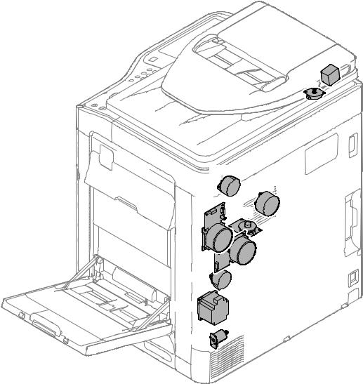
11. Fans and filter
PROFM1
POFM
FUFM
HDDFAN
|
PROFM2 |
LSUFM |
PSFM |
|
|
|
1 |
Signal name |
Name |
Function/Operation |
FUFM |
Fusing cooling fan motor |
Cools the fusing unit. |
HDDFM |
HDD cooling fan motor |
Cools the HDD. |
LSUFM |
LSU cooling fan motor |
Cools the LSU. |
POFM |
Paper exit cooling fan motor |
Cools the paper exit section. |
PROFM1 |
Process fan motor 1 |
Cools the process section. |
PROFM2 |
Process fan motor 2 |
Exhausts ozone. |
PSFM |
Power PWB cooling fan motor |
Cools the power PWB. |
No. |
Name |
Function/Operation |
1 Ozone filter |
Absorbs ozone generated in the image process section. |
|
MX-B401 EXTERNAL VIEW AND INTERNAL STRUCTURE 3 – 10
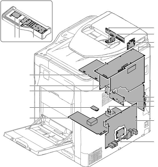
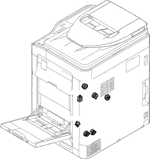
12. PWB
|
|
4 |
|
|
5 |
1 |
2 |
3 |
|
|
6 |
|
|
7 |
 8
8
18
17
16
9
10
15 |
11 |
|
14
12
13
No. |
Name |
Function/Operation |
1 |
MFP OPE-P PWB |
Outputs the key operation signal. |
2 |
LCD INV PWB |
Generates the high voltage for the LCD back-light. |
3 |
LVDS PWB |
Converts the display signal and outputs to the LCD. |
4 |
CL inverter PWB |
Drives the scanner lamp. |
5 |
CCD PWB |
Scans the document images. |
6 |
RSPF driver PWB |
Controls the RSPF. |
7 |
Scanner control PWB |
Controls the scanner section. |
8 |
PCU PWB |
Controls the engine section. |
9 |
MFPC PWB |
Controls images and the whole machine. |
10 |
LD PWB |
Controls laser lighting. |
11 |
BD PWB |
Detects laser and outputs the synchronous signal. |
12 |
ACDC power PWB |
Controls the primary side power source and outputs the secondary side voltage. |
13 |
Paper size detection PWB |
Detects the paper size in the tray 1. |
14 |
MC PWB |
Generates the high voltage for the main charger and the developing bias voltage. |
15 |
DV initial PWB |
Detects the DV model. |
16 |
LSU MOTHER PWB |
Controls the LSU. Interfaces the MFPC PWB and PCU PWB. |
17 |
HL PWB |
Controls the heater lamp. |
18 |
TC PWB |
Generates each transfer voltage and separation voltage. |
MX-B401 EXTERNAL VIEW AND INTERNAL STRUCTURE 3 – 11
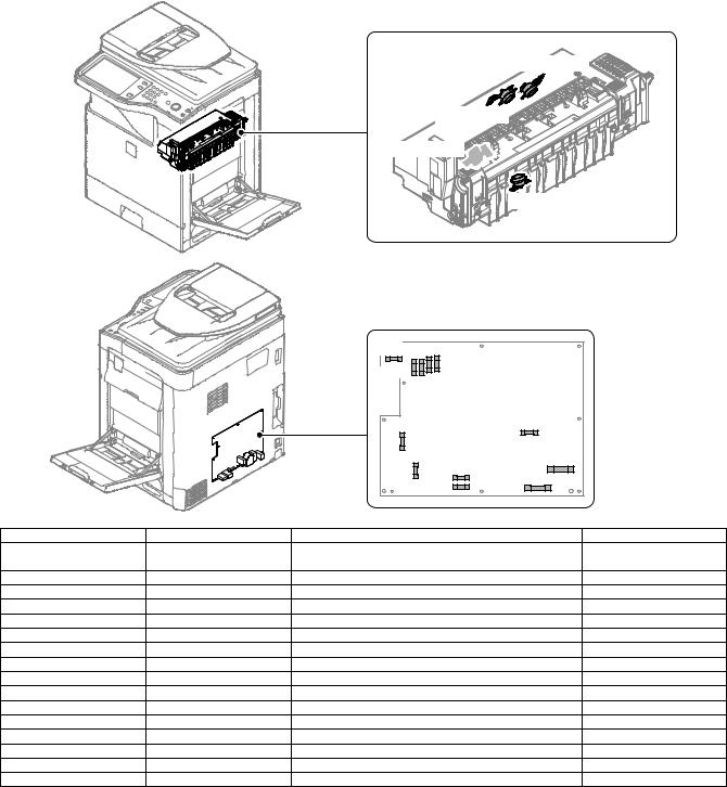
13. Fuses and Thermostats
RDTCT_EX2
RDTCT_EX1
RDTCT_Main
RDTCT_Low
|
|
F401 |
F405 |
|
|
|
|
|
F404 |
|
|
|
|
F402 |
|
|
|
|
|
|
F403 |
|
|
|
|
|
F201 |
F301 |
|
|
|
|
|
|
|
|
|
|
F101 |
F002 |
|
|
|
|
|
|
|
|
|
|
F004 |
F001 |
|
|
|
|
F003 |
|
|
Signal name |
Name |
|
Specifications |
|
Section |
F001 |
Fuse |
AC250V T10AH (200V series) |
|
ACDC power PWB |
|
|
|
AC250V 20A (120V series) |
|
|
|
F002 |
Fuse |
AC250V T10AH (200V series) (Not provided in 120V series) |
ACDC power PWB |
||
F003 |
Fuse |
AC250V T2AH (Common in 200V series and 120V series) |
ACDC power PWB |
||
F004 |
Fuse |
AC250V T2AH (200V series) (Not provided in 120V series) |
ACDC power PWB |
||
F101 |
Fuse |
AC250V T2AH (Common in 200V series and 120V series) |
ACDC power PWB |
||
F201 |
Fuse |
AC250V T5AH (Common in 200V series and 120V series) |
ACDC power PWB |
||
F301 |
Fuse |
AC250V T2AH (Common in 200V series and 120V series) |
ACDC power PWB |
||
F401 |
Fuse |
AC250V T4AH (Common in 200V series and 120V series) |
ACDC power PWB |
||
F402 |
Fuse |
AC250V T6.3AH (Common in 200V series and 120V series) |
ACDC power PWB |
||
F403 |
Fuse |
AC250V T6.3AH (Common in 200V series and 120V series) |
ACDC power PWB |
||
F404 |
Fuse |
AC250V T6.3AH (Common in 200V series and 120V series) |
ACDC power PWB |
||
F405 |
Fuse |
AC250V T6.3AH (Common in 200V series and 120V series) |
ACDC power PWB |
||
RDTCT_EX1 |
External thermostat |
Prevents against overheating of the fusing roller. |
|
Fusing unit |
|
RDTCT_EX2 |
External thermostat 2 |
Prevents against overheating of the fusing roller. |
|
Fusing unit |
|
RDTCT_Low |
Lower thermostat |
Prevents against overheating of the fusing roller. |
|
Fusing unit |
|
RDTCT_Main |
Upper thermostat |
Prevents against overheating of the fusing roller. |
|
Fusing unit |
|
MX-B401 EXTERNAL VIEW AND INTERNAL STRUCTURE 3 – 12
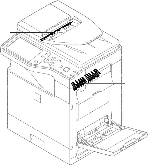
14. Gates
1
2
No. |
Name |
Function/ Operation |
1 |
Switchback gate |
Guides paper which is switched back by the paper exit roller to the switchback section in the duplex copy mode. |
2 |
RSPF reverse gate |
Guides paper which is switched back by the paper exit roller to the transport roller 4 when duplex scanning of a |
|
|
document is performed. |
MX-B401 EXTERNAL VIEW AND INTERNAL STRUCTURE 3 – 13
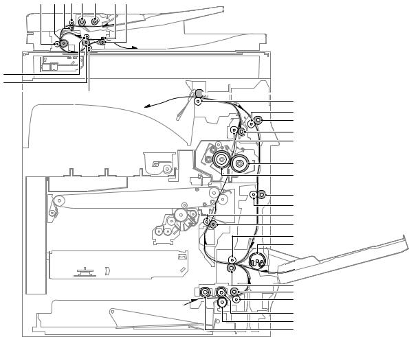
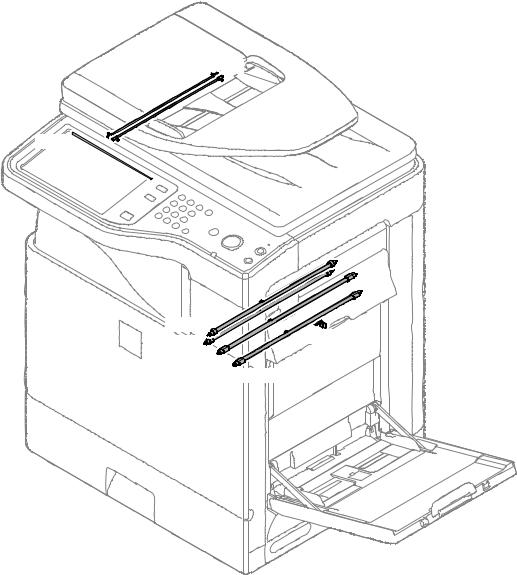
15. Rollers
4 |
5 |
6 7 |
8 |
9 |
10 11 |
3
2
1 

 12
12
13
14
15
16
17
18
19
20
21
22
23
24
25
26 |
27 |
28 |
29 |
30 |
31 |
No. |
Name |
Function/ Operation |
1 |
Transport roller 3 (Idle) (RSPF) |
Applies a pressure to the document and the transport roller to give a transport power of the transport roller |
|
|
to the document. |
2 |
Transport roller 3 (Drive) (RSPF) |
Transports the document from the transport roller 2 to the paper exit roller. |
|
|
Transports the document switched back by the paper exit roller to the transport roller 2 in the duplex |
|
|
scanning mode. |
3 |
Transport roller 4 (Idle) (RSPF) |
Applies a pressure to the document and the transport roller to give a transport power of the transport roller |
|
|
to the document. |
4 |
Transport roller 2 (Idle) (RSPF) |
Applies a pressure to the document and the transport roller to give a transport power of the transport roller |
|
|
to the document. |
5 |
Transport roller 2 (Drive) (RSPF) |
Transports the document from the transport roller 1 to the transport roller 3. |
6 |
Transport roller 1 (Drive) (RSPF) |
Transports the document fed from the document tray to the transport roller 2. |
7 |
Transport roller 1 (Idle) (RSPF) |
Applies a pressure to the document and the transport roller to give a transport power of the transport roller |
|
|
to the document. |
8 |
Paper feed roller (RSPF) |
Feeds the document to the transport section. |
9 |
Paper pickup roller (RSPF) |
Transports the document to the separation roller. |
10 |
Paper exit roller (Idle) (RSPF) |
Applies a pressure to the document and the transport roller to give a transport power of the transport roller |
|
|
to the document. |
11 |
Paper exit roller (Drive) (RSPF) |
Discharges the document. Transports the document to the transport roller 2 in the duplex scanning mode. |
12 |
Paper exit roller (Drive) |
Discharges the paper. / Transports the paper to the switchback section. |
13 |
Paper exit roller (Idle) |
Applies a pressure to the paper and the paper exit roller to give a transport power of the paper exit roller to |
|
|
the paper. |
14 |
Transport roller 4 (Idle) |
Applies a pressure to the paper and the transport roller to give a transport power of the transport roller to |
|
|
the paper. |
15 |
Transport roller 4 (Drive) |
Transports the paper switched back by the paper exit roller to the transport roller 5. |
16 |
Transport roller 3 (Drive) |
Transports the paper from the fusing roller to the paper exit roller. |
17 |
Transport roller 3 (Idle) |
Applies a pressure to the paper and the transport roller to give a transport power of the transport roller to |
|
|
the paper. |
18 |
Fusing roller (Heating) |
Heats and presses toner on the paper to fuse on the paper. |
19 |
Fusing roller (Pressing) |
Applies a pressure to the fusing roller (heating). |
20 |
Transport roller 5 (Drive) |
Transports the paper from the transport roller 4 to the transport roller 2. |
MX-B401 EXTERNAL VIEW AND INTERNAL STRUCTURE 3 – 14
No. |
Name |
Function/ Operation |
21 |
Transport roller 5 (Idle) |
Applies a pressure to the paper and the transport roller to give a transport power of the transport roller to |
|
|
the paper. |
22 |
Resist roller (Idle) |
Applies a pressure to the paper and the resist roller, giving a transport power of the resist roller to the |
|
|
paper. |
23 |
Resist roller (Drive) |
Transports paper to the transfer section. / Controls the paper transport timing, and adjusts the relative |
|
|
relations between images and paper. |
24 |
Transport roller 2 (Idle) |
Applies a pressure to the paper and the transport roller to give a transport power of the transport roller to |
|
|
the paper. |
25 |
Paper feed roller (Manual paper feed tray) |
Transports paper to the transport roller 2. |
26 |
Transport roller 2 (Drive) |
Transports the paper transported from the transport roller 1 to the resist roller. |
27 |
Transport roller 1 (Drive) |
Transports paper which was fed from the paper feed tray 1 to the transport roller 2. |
28 |
Transport roller 1 (Idle) |
Applies a pressure to the paper and the transport roller to give a transport power of the transport roller to |
|
|
the paper. |
29 |
Paper feed roller (No. 1 paper feed tray) |
Transport paper to the paper transport section. |
30 |
Separation roller (No. 1 paper feed tray) |
Separates paper to prevent against double feed. |
31 |
Paper pickup roller (No. 1 paper feed tray) |
Transports paper to the paper feed roller. |
MX-B401 EXTERNAL VIEW AND INTERNAL STRUCTURE 3 – 15
[4] ADJUSTMENTS
1. General
Each adjustment item in the adjustment item list is associated with a specific Job number. Perform the adjustment procedures in the sequence of Job numbers from the smallest to the greatest.
However, there is no need to perform all the adjustment items. Perform only the necessary adjustments according to the need.
Unnecessary adjustments can be omitted. Even in this case, however, the sequence from the smallest to the greatest Job number must be observed.
If the above precaution should be neglected, the adjustment would not complete normally or trouble may occur.
2. Adjustment item list
Job No |
|
|
|
|
Adjustment item list |
Simulation |
ADJ 1 |
Adjusting high voltage values |
|
1A |
Adjust the main charger grid voltage |
8-2 |
|
|
|
|
|
1B |
Adjust the developing bias voltage |
8-1 |
|
|
|
|
1C |
Transfer voltage adjustment |
8-6 |
ADJ 2 |
Image density sensor adjustment |
|
|
44-2 |
||
ADJ 3 |
Image skew adjustment (LSU unit) |
|
|
64-2 |
||
ADJ 4 |
Print engine image magnification ratio adjustment (Main scanning direction) (Print engine section) (Manual adjustment) |
50-10 |
||||
ADJ 5 |
Image off-center adjustment (Print engine section) |
50-10 |
||||
ADJ 6 |
Scan image magnification ratio |
|
6A |
Scan image magnification ratio adjustment (Main scanning direction) (Document table mode) |
48-1 |
|
|
adjustment (Document table |
|
|
6B |
Scan image magnification ratio adjustment (Sub scanning direction) (Document table mode) |
48-1 |
|
mode) |
|
|
|
|
|
ADJ 7 |
Scan image magnification ratio |
|
7A |
Scan image magnification ratio adjustment (Main scanning direction) (RSPF mode) |
48-1 |
|
|
adjustment (Main/sub scanning |
|
|
7B |
Scan image magnification ratio adjustment (Sub scanning direction) (RSPF mode) |
48-1 |
|
direction) (RSPF mode) |
|
|
|
|
|
ADJ 8 |
Scan image off-center |
|
8A |
Scan image off-center adjustment (Document table mode) |
50-12 |
|
|
adjustment |
|
|
8B |
Scan image off-center adjustment (RSPF mode) |
50-12 |
ADJ 9 |
Print area (Void area) adjustment (Print engine section) |
50-10/50-1 |
||||
ADJ 10 |
Copy image position, image loss |
|
10A |
Copy image position, image loss adjustment (Document table mode) |
50-1 (50-2) |
|
|
adjustment |
|
|
10B |
Adjust the original scan start position (Adjust the scanner read position in RSPF mode front |
53-8 |
|
|
|
|
|
face scan) |
|
|
|
|
|
10C |
Copy image position, image loss adjustment (RSPF mode) |
50-6 (50-7) |
ADJ 11 |
Print lead edge image position adjustment (Printer mode) (Print engine section) |
50-5 |
||||
ADJ 12 |
Copy density and gradation |
|
12A |
CCD gamma adjustment (CCD calibration) |
63-3 (63-5) |
|
|
adjustment |
|
|
12B |
Copy density and gradation adjustment (Auto adjustment) |
46-24 |
|
|
|
|
12C |
Copy density and gradation adjustment (Manual adjustment) |
46-21 |
|
|
|
|
12D |
Copy density and gradation adjustment (Each copy mode) (Whole adjustment) |
46-2 |
|
|
|
|
|
(Normally unnecessary to adjust) |
|
|
|
|
|
12E |
Condition setting of document density reading operation (exposure) in the auto copy mode |
46-19 |
|
|
|
|
|
(Normally not required) |
|
|
|
|
|
12F |
Document background density reproducibility adjustment in the auto copy mode (Normally |
46-32 |
|
|
|
|
|
unnecessary to adjust) |
|
|
|
|
|
12G |
Color document reproducibility adjustment in the copy mode |
46-37 |
|
|
|
|
|
(Normally unnecessary to adjust) |
|
|
|
|
|
12H |
Sharpness adjustment in the auto copy mode (Normally unnecessary to adjust) |
46-60 |
|
|
|
|
12I |
Copy high density part density correction setting (Prevents against tone gap) |
46-23 |
|
|
|
|
|
(Normally unnecessary to adjust) |
|
|
|
|
|
12J |
Copy density and gradation adjustment in the RSPF mode (Normally unnecessary to adjust) |
46-9 |
|
|
|
|
12K |
Auto copy density and gradation adjustment by the user |
46-53 |
|
|
|
|
|
(Copy auto adjustment enable setting and adjustment) |
|
ADJ 13 |
Printer density and gradation |
|
13A |
Printer density and gradation adjustment (Auto adjustment) |
67-24 |
|
|
adjustment |
|
|
13B |
Printer density and gradation adjustment (Manual adjustment) |
67-25 |
|
|
|
|
13C |
Printer density and gradation adjustment (low density part density and gradation adjustment) |
67-36 |
|
|
|
|
|
(Normally unnecessary to adjust) |
|
|
|
|
|
13D |
Printer high density part density correction setting |
67-34 |
|
|
|
|
|
(High density part tone gap countermeasure) (Normally unnecessary to the setting change) |
|
|
|
|
|
13E |
Auto density and gradation adjustment by the user (Printer auto adjustment ENABLE setting |
26-54 |
|
|
|
|
|
and adjustment) |
|
|
|
|
|
13F |
Copy/Printer density and gradation adjustment (Automatic adjustment) |
46-74 |
ADJ 14 |
Manual paper feed tray paper size (width) sensor adjustment |
40-2 |
||||
ADJ 15 |
Touch panel coordinate setting |
|
|
65-1 |
||
ADJ 16 |
Image loss, void area, image off- |
|
16A |
Print image main scanning direction image magnification ratio automatic adjustment |
50-28 |
|
|
center, image magnification ratio |
|
|
16B |
Image off-center automatic adjustment (Document table mode) |
50-28 |
|
auto adjustment with SIM50-28 |
|
|
16C |
Copy lead edge image reference position adjustment, image off-center, sub scanning |
50-28 |
|
|
|
|
|
direction image magnification ratio automatic adjustment (Document table mode) |
|
|
|
|
|
16D |
SPF mode image off-center, image lead edge position, sub scanning direction image |
50-28 |
|
|
|
|
|
magnification ratio automatic adjustment (RSPF mode) |
|
ADJ 17 |
Fusing paper guide position adjustment |
|
|
|||
MX-B401 ADJUSTMENTS 4 – 1
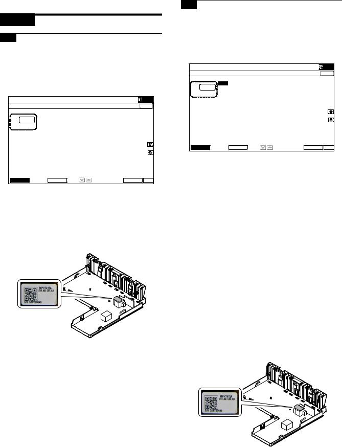
3. Details of adjustment
ADJ 1 Adjusting high voltage values
1-B Adjust the developing bias voltage
This adjustment is needed in the following situations:
*When the MC high voltage power PWB is replaced.
*U2 trouble has occurred.
1-A Adjust the main charger grid voltage
This adjustment is needed in the following situations:
*The PCU PWB has been replaced.
*The EEPROM of the PCU PWB has been replaced.
* When the MC high voltage power PWB is replaced. |
1) Go through the modes specified in Simulation 8-1. |
*U2 trouble has occurred.
*The PCU PWB has been replaced.
*The EEPROM of the PCU PWB has been replaced.
1)Enter the SIM 8-2 mode.
|
|
|
6,08/$7,21 |
12 |
&/26( |
||
7(67 |
||||||
0+9 *5,' 6(77,1* $1' 287387 |
|
|||||
|
|
|
|
|
0,''/( 63((' *%B. |
|
|
|
|
|
$ |
|
|
|
|
|
|
|
|
|
|
|
|
|
|
|
|
|
|
|
|
|
|
|
|
|
|
|
|
|
|
|
|
|
|
|
|
|
|
|
|
|
|
|
|
|
|
|
|
|
|
|
|
|
|
|
|
|
|
|
|
|
|
|
|
|
|
|
|
|
|
|
|
|
|
|
|
|
|
|
|
|
|
|
|
|
|
|
0,''/( |
/2: |
(;(&87( |
2. |
|
2)Select an output mode and an item to be adjusted.
3)Enter the adjustment value (specified value) in the middle speed mode, and press [OK] key.
When [EXECUTE] key is pressed, the voltage entered in the procedure 3 is outputted for 30sec and the set value is saved. When [EXECUTE] key is pressed, the output is stopped.
Enter the adjustment value of each mode which is specified on the label attached on the MC high voltage power PWB.
NOTE: Note that the adjustment value may differ depending on the MC high voltage power PWB.
Since the adjustment value label is attached on the MC high voltage PWB, the PWB must be removed in order to check the adjustment value.
This is a troublesome procedure. Therefore, it is advisable to put down the adjustment value in advance.
Mode |
|
Item/Display |
Content |
Setting range |
MIDDLE |
A |
MIDDLE |
K charging/grid bias set |
150 - 850 |
|
|
SPEED GB_K |
value at middle speed |
|
LOW |
A |
LOW SPEED |
K charging/grid bias set |
150 - 850 |
|
|
GB_K |
value at low speed |
|
GBK:XXX
When the adjustment value (specified value) of the middle speed mode is set, the adjustment values of the other modes are automatically set according to the middle speed mode setting in a certain relationship.
NOTE: Since the high voltage output cannot be checked with a digital multi meter in this model, a judgment of the output must be made by checking the print image quality.
|
|
|
6,08/$7,21 |
12 |
&/26( |
|
7(67 |
|||
'9 6(77,1* $1' 287387 |
|
|||
$ 0,''/( 63((' '9%B.
|
|
|
|
|
|
|
|
|
|
|
|
|
|
|
|
|
|
|
|
|
|
|
|
|
|
|
|
|
|
|
|
|
|
|
|
|
|
|
|
|
|
|
|
|
|
|
|
|
|
|
|
|
|
|
|
|
|
|
|
|
|
|
|
|
|
|
|
|
|
|
|
|
|
|
|
|
|
|
|
|
|
|
|
|
0,''/( |
/2: |
(;(&87( |
2. |
|
2)Select an output mode and an item to be adjusted.
3)Enter the adjustment value (specified value) in the middle speed mode, and press [OK] key.
When [EXECUTE] key is pressed, the voltage entered in the procedure 3 is outputted for 30sec and the set value is saved. When [EXECUTE] key is pressed, the output is stopped.
Enter the adjustment value of each mode which is specified on the label attached on the MC high voltage power PWB.
NOTE: Note that the adjustment value may differ depending on the MC high voltage power PWB.
Since the adjustment value label is attached on the MC high voltage PWB, the PWB must be removed in order to check the adjustment value.
This is a troublesome procedure. Therefore, it is advisable to put down the adjustment value in advance.
Mode |
|
Item/Display |
Content |
Setting |
|
range |
|||
|
|
|
|
|
MIDDLE |
A |
MIDDLE SPEED |
K developing bias set |
0-600 |
|
|
DVB_K |
value at middle speed |
|
LOW |
A |
LOW SPEED |
K developing bias set |
0-600 |
|
|
DVB_K |
value at low speed |
|
DVK:XXX
When the adjustment value (specified value) of the middle speed mode is set, the adjustment values of the other modes are automatically set according to the middle speed mode setting in a certain relationship.
NOTE: Since the high voltage output cannot be checked with a digital multi meter in this model, a judgment of the output must be made by checking the print image quality.
MX-B401 ADJUSTMENTS 4 – 2
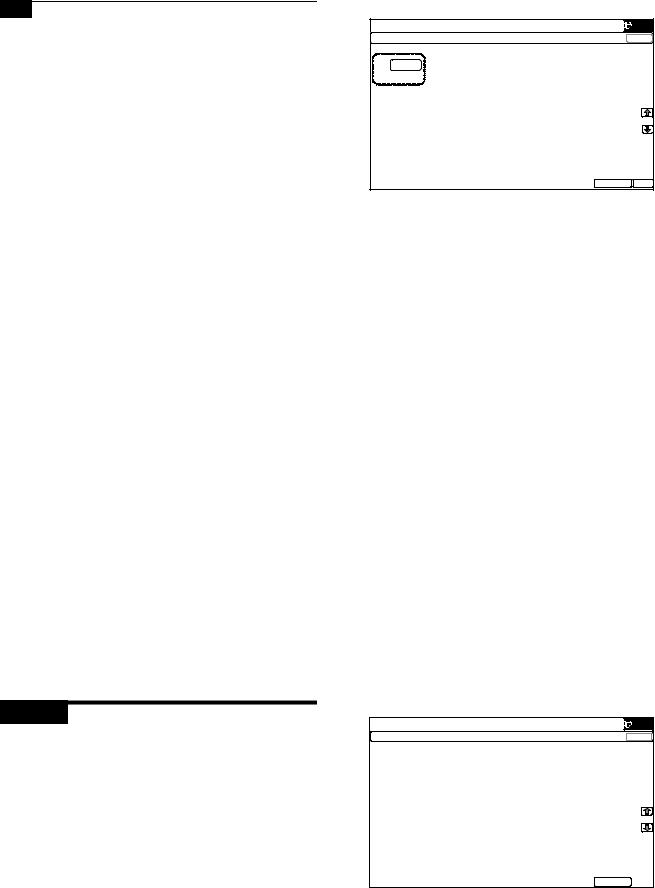
1-C Transfer voltage adjustment
This adjustment is needed in the following situations:
*When the TC high voltage PWB is replaced.
*U2 trouble has occurred.
*The PCU PWB has been replaced.
*The EEPROM of the PCU PWB has been replaced.
1)Go through the modes specified in Simulation 8-6.
|
|
|
6,08/$7,21 |
12 |
|
&/26( |
||||
7(67 |
|
||||||||
|
|
|
|
|
|
|
|||
7+9 6(77,1* $1' 287387 |
|
|
|
||||||
|
|
|
|
|
|
|
|
|
|
|
|
|
|
|
$ |
|
|
7& /2: 63((' %: . |
|
$ |
|
|
|
|
|
|
|
||
|
|
% |
|
|
7& 0,''/( 63((' %: . |
|
|||
|
|
|
|
|
|
|
|||
|
|
|
& |
|
|
7& 3/$,1 %: 63; |
|
||
|
|
|
|
|
|
|
7& 3/$,1 %: '3; |
|
|
|
|
|
|
|
' |
|
|
|
|
|
|
|
|
|
|
|
7& +($9< %: 63; |
|
|
|
|
|
|
|
( |
|
|
|
|
|
|
|
|
|
|
|
|
|
|
|
|
|
|
|
) |
|
|
7& +($9< %: '3; |
|
|
|
|
|
|
|
|
|
|
|
|
|
|
|
|
* |
|
|
7& 2+3 %: |
|
|
|
|
|
|
|
|
7& (19(/23( %: |
|
|
|
|
|
|
|
+ |
|
|
|
|
|
|
|
|
|
|
|
|
|
|
|
|
|
|
|
, |
|
|
7& 7+,1 %: |
|
|
|
|
|
|
|
|
|
|
|
|
|
|
|
|
- |
|
|
7& */266< %: |
|
|
|
|
|
|
|
|
|
|
|
|
|
|
|
|
. |
|
|
7& &/($1,1* |
|
|
|
|
|
|
|
|
|
|
|
|
|
|
|
|
/ |
|
|
7& &/($1 /2: 63' |
|
|
|
|
|
|
|
|
|
(;(&87( |
2. |
|
|
|
|
|
2) Select an item to be adjusted. |
|
|
|
|
||
|
|
|
|
|
Enter the adjustment value (specified value), and press [OK] |
||||||
|
|
|
|
|
key. |
|
|
|
|
|
|
|
|
|
|
|
When [EXECUTE] key is pressed, the voltage entered in the |
||||||
|
|
|
|
|
procedure 3 is outputted for 30sec and the set value is saved. |
||||||
|
|
|
|
|
When [EXECUTE] key is pressed, the output is stopped. |
||||||
|
|
|
|
|
By setting the default value (specified value), the specified out- |
||||||
|
|
|
|
|
put is provided. |
|
|
|
|
|
|
|
|
|
|
|
|
|
|
|
|
||
|
|
|
|
|
|
Adjustment |
Default |
Actual output |
Default value |
||
|
Item/Display |
|
Content |
|
|
of actual |
|||||
|
|
|
|
range |
value |
setting range |
|||||
|
|
|
|
|
|
output value |
|||||
|
|
|
|
|
|
|
|
|
|||
A |
TC1 LOW SPEED BW K |
Primary transfer bias |
Low speed mode |
51 - 255 |
95 |
2 - 30 A |
8 A |
||||
B |
TC1 MIDDLE SPEED BW K |
reference value |
Middle speed mode |
51 - 255 |
131 |
|
13 |
|
A |
||
|
2 - 30 A |
|
|||||||||
C |
TC2 PLAIN BW SPX |
Secondary transfer |
Standard |
|
Front surface mode |
51 - 255 |
111 |
–2 - –80 A |
–25 A |
||
D |
TC2 PLAIN BW DPX |
bias reference value |
paper mode |
|
Back surface mode |
51 - 255 |
111 |
–2 - –80 A |
–25 A |
||
E |
TC2 HEAVY BW SPX |
|
Heavy paper |
|
Front surface mode |
51 - 255 |
93 |
–2 - –80 A |
–10 A |
||
F |
TC2 HEAVY BW DPX |
|
mode |
|
Back surface mode |
51 - 255 |
93 |
–2 - –80 A |
–10 A |
||
G |
TC2 OHP BW |
|
|
|
OHP |
51 - 255 |
85 |
–2 - –80 A |
–8 A |
||
H |
TC2 ENVELOPE BW |
|
|
Envelope |
51 - 255 |
124 |
–2 - –80 A |
–30 A |
|||
I |
TC2 THIN BW |
|
|
Thin paper |
51 - 255 |
111 |
–2 - –80 A |
–25 A |
|||
J |
TC2 GLOSSY BW |
|
Gloss paper |
51 - 255 |
72 |
–2 - –80 A |
–10 A |
||||
K |
TC2 CLEANING |
|
Cleaning mode |
51 - 255 |
67 |
–2 - -80 A |
–8 A |
||||
L |
TC2 CLEAN LOW SPD |
Secondary transfer |
Low speed print mode |
0 - 255 |
16 |
–100V - 1500V |
0V |
||||
M |
TC2 CLEAN MIDDLE SPD |
cleaning bias |
Middle speed print mode |
0 - 255 |
16 |
–100V - 1500V |
0V |
||||
N |
TC2 CLEAN CLEANING |
reference value |
Cleaning mode |
0 - 255 |
143 |
–100V - 1500V |
800V |
||||
O |
PTC LOW SPEED BW |
PTC current output |
Low speed mode |
0 - 255 |
133 |
0 A - –700 A |
–300 A |
||||
P |
PTC MIDDLE SPEED BW |
reference value |
Middle speed mode |
0 - 255 |
133 |
0 A - –700 A |
–300 A |
||||
Q |
CASE VOLT LOW BW |
PTC case voltage |
Low speed mode |
0 - 255 |
0 |
0V - –1000V |
0V |
||||
R |
CASE VOLT MID BW |
reference value |
Middle speed mode |
0 - 255 |
0 |
0V - –1000V |
0V |
||||
S |
PEEL VOLT LOW BW |
Separation discharge |
Low speed mode |
51 - 255 |
200 |
–50 - –3000V |
–2200V |
||||
T |
PEEL VOLT MIDDLE BW |
reference value |
Middle speed mode |
51 - 255 |
200 |
–50 - –3000V |
–2200V |
||||
ADJ 2 Image density sensor adjustment
NOTE: Before executing this adjustment, check to confirm the following items.
*Check to confirm that the image density sensor is clean.
*Check to confirm that the transfer belt is clean and free from scratches.
NOTE: This adjustment executes automatically at the outset of registration adjustment operation and process control operation as well as SIM44-2.
Normally, therefore, it is not required to perform this adjustment. It is performed only when the sensor is replaced or when the adjustment result is checked.
1)Enter SIM44-2 mode.
|
|
|
6,08/$7,21 |
12 |
|
&/26( |
7(67 |
|
||||
352&21 *$,1 $'-8670(17 |
|
|
|||
|
|
3&6B. /(' $'- |
5(*B5 %(/7 0$; |
|
|
|
|
3&6B. '$5. |
5(*B5 %(/7 0,1 |
|
|
|
|
3&6B. *51' |
5(*B5 %(/7 ',) |
|
|
|
|
3&6B. %(/7 0$; |
|
|
|
|
|
3&6B. %(/7 0,1 |
5(*B5 3$7&+ . |
|
|
|
|
3&6B. %(/7 ',) |
|
|
|
|
|
5(*B5 /(' $'- |
|
|
|
|
|
5(*B5 '$5. |
|
|
|
|
|
5(*B5 *51' |
|
|
|
|
|
|
|
(;(&87( |
|
MX-B401 ADJUSTMENTS 4 – 3
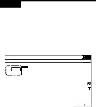
2)Press [EXECUTE] key.
The image density sensor is automatically adjusted.
After completion of the adjustment, the adjustment result is displayed and [EXECUTE] key returns to the normal display.
|
Display/Item |
Content |
Range |
Default |
A |
PCS_K LED ADJ |
Image density sensor light |
1 - 255 |
21 |
|
|
emitting quantity |
|
|
|
|
adjustment value |
|
|
B |
PCS_K DARK |
Dark voltage |
0 - 255 |
0 |
C |
PCS_K GRND |
Belt base detection level |
0 - 255 |
0 |
|
|
when completion of Item A |
|
|
|
|
adjustment |
|
|
D |
PCS_K BELT MAX |
Maximum value of belt |
0 - 255 |
0 |
|
|
base detection level |
|
|
E |
PCS_K BELT MIN |
Minimum value of belt |
0 - 255 |
0 |
|
|
base detection level |
|
|
F |
PCS_K BELT DIF |
Belt base detection level |
0 - 255 |
0 |
|
|
difference |
|
|
|
|
(Item D - Item E) |
|
|
G |
REG_R LED ADJ |
Image density sensor light |
1 - 255 |
32 |
|
|
emitting quantity |
|
|
|
|
adjustment value |
|
|
H |
REG_R DARK |
Image density sensor dark |
0 - 255 |
0 |
|
|
voltage |
|
|
I |
REG_R GRND |
Belt base detection level |
0 - 256 |
0 |
|
|
when completion of Item |
|
|
|
|
G adjustment |
|
|
J |
REG_R BELT MAX |
Maximum value of belt |
0 - 255 |
0 |
|
|
base detection level |
|
|
K |
REG_R BELT MIN |
Minimum value of belt |
0 - 255 |
0 |
|
|
base detection level |
|
|
L |
REG_R BELT DIF |
Belt base detection level |
0 - 255 |
0 |
|
|
difference (Item J - Item K) |
|
|
M |
REG_R PATCH (K) |
Patch detection level for |
0 - 255 |
0 |
|
|
check |
|
|
If the adjustment is not completed normally, "ERROR" is displayed.
Error name |
Error content |
Image density sensor |
PCS_K LED ADJ error |
adjustment abnormality |
The target is not reached by 3 times of |
|
retry. |
Substrate scan abnormality |
PCS_K GRND error |
|
Effective difference between the upper |
|
and lower values of the belt substrate |
|
circuit, outside the range |
Registration sensor R |
REG_R LED ADJ error |
adjustment abnormality |
The target is not reached by 3 times of |
|
retry. |
Registration substrate R |
REG_R GRND error |
scan abnormality |
Effective difference between the upper |
|
and lower values of the belt substrate |
|
circuit, outside the range |
Error display |
|
Error content |
|
BK_SEN_ADJ |
Image density |
|
PCS_K LED ADJ error (The |
_ERR |
sensor adjustment |
|
target value is not obtained after |
|
abnormality |
|
retried three times.) |
BELT_READ |
Transfer belt |
|
PCS_K GRND error (The surface |
_ERR |
surface reading |
|
detection level is maximum or the |
|
abnormality |
|
minimum value difference is |
|
|
|
outside a reference range.) |
REG_SEN_R |
Sensor adjustment |
|
REG_R LED ADJ error (The |
_ADJ_ERR |
abnormality |
|
target value is not obtained after |
|
|
|
retried three times.) |
REG_BELT_R |
Transfer belt |
|
REG_R GRND error (The |
_READ_ERR |
surface reading |
|
surface detection level is |
|
abnormality |
|
maximum or the minimum value |
|
|
|
difference is outside a reference |
|
|
|
range.) |
When an error occurs, check the following sections for any abnormality.
•Image density sensor
•PCU PWB
•Transfer belt (dirt, scratch)
•Transfer belt cleaner
If any abnormality is found, repair and adjust again.
If an error occurs, the adjustment result is not revised.
ADJ 3 Image skew adjustment (LSU unit)
This adjustment is needed in the following situations:
*When the LSU unit is replaced.
*When the LSU unit is removed from the main unit.
The image skew adjustment (LSU unit) is performed by changing the parallelism of the LSU unit scan laser beams for the OPC drum.
1)Enter SIM64-2 mode.
Set the set items to the values shown below.
A: 1 |
B: 1 |
|
C: 254 |
D: 255 |
|
|
||
|
|
|
|
|
|
|
|
|
7(67 6,08/$7,21 |
12 |
|
|
|
|
&/26( |
||
6(/) 35,17 %: 6(59,&( |
|
|
|
|
|
|||
|
|
$ |
|
35,17 3$77(51 |
|
|
||
$ |
|
% |
|
'27 '27 |
,) $ |
|
||
|
& |
|
'27 '27 |
,) $ |
|
|
|
||
|
' |
|
'(16,7< ),;(' ,) $ |
|
|
|
|
08/7, &2817 |
|
|
( |
|
|
|
|
|
|
(;32685( |
,) $ 67$1'$5' ',7+(5 |
|
) |
|
||
|
|
|
||
|
|
|
||
|
* |
|
3$3(5 &6 |
|
|
|
|
||
|
+ |
|
'83/(; 12 |
|
|
|
|
3$3(5 7<3( 3/$,1 |
|
|
, |
|
||
|
|
|
|
|
|
|
|
|
|
|
|
|
|
|
|
|
|
|
|
|
|
|
|
|
|
|
|
|
|
(;(&87( 2.
2)Select the tray with A4 (11" x 8.5") paper in it.
3)Press [EXECUTE] key.
The check pattern is printed out.
4)Check the printed image for any skew.
There are following two methods of checking the image for any skew (right angle).
Method 1:
Measure the length of the diagonal lines of the rectangle print pattern. Check the difference in the length of the diagonal lines for judgment of good or no good
Method 2:
Compare the right angle of vertical side/horizontal side of the rectangle print pattern and the right angle sides of A4 (11" x 8.5") paper for judgment of good or no good.
(NOTE)
In the case of Method 2, the right angle of paper to be used may not be exact. Be sure to check the right angle of paper to be used in advance.
MX-B401 ADJUSTMENTS 4 – 4
Loading...