


 Loading...
MX-M160D MX-M160
SERVICE MANUAL
CODE : 00ZMXM200DS1E
DIGITAL
MULTIFUNCTIONAL
SYSTEM
MX-M200D
MX-M200DK
MX-M160D
MX-M160DK
MX-M200D MODEL MX-M160
As for the content of the MX-M200DK/MX-M160DK, refer to the content of the MX-M200D/MX-M160D as long as there is no proviso.
CONTENTS
[ 1 ] |
GENERAL . . . . . . . . . . . . . . . . . . . . . . . . . . . . . . . . . . . . . . . . |
. 1 |
- 1 |
|
[ 2 ] |
CONFIGURATION. . . . . . . . . . . . . . . . . . . . . . . . . . . . . . . . . . . |
2 |
- 1 |
|
[ 3 ] |
SPECIFICATIONS. . . . . . . . . . . . . . . . . . . . . . . . . . . . . . . . . . . |
3 |
- 1 |
|
[ 4 ] |
CONSUMABLE PARTS. . . . . . . . . . . . . . . . . . . . . . . . . . . . . . . |
4 |
- 1 |
|
[ 5 ] |
EXTERNAL VIEWS AND INTERNAL STRUCTURES . . . . . . . |
5 |
- 1 |
|
[ 6 |
] |
ADJUSTMENTS . . . . . . . . . . . . . . . . . . . . . . . . . . . . . . . . . . . . |
6 |
- 1 |
[ 7 |
] |
SIMULATIONS . . . . . . . . . . . . . . . . . . . . . . . . . . . . . . . . . . . . . |
7 |
- 1 |
[ 8 |
] |
USER PROGRAMS . . . . . . . . . . . . . . . . . . . . . . . . . . . . . . . . . |
8 |
- 1 |
[ 9 |
] |
TROUBLE CODE LIST . . . . . . . . . . . . . . . . . . . . . . . . . . . . . . . |
9 |
- 1 |
[10] |
MAINTENANCE . . . . . . . . . . . . . . . . . . . . . . . . . . . . . . . . . . . |
10 |
- 1 |
|
[11] |
DISASSEMBLY AND ASSEMBLY . . . . . . . . . . . . . . . . . . . . . . |
11 |
- 1 |
|
[12] |
FLASH ROM VERSION UP PROCEDURE . . . . . . . . . . . . . . |
12 |
- 1 |
|
[13] |
ELECTRICAL SECTION . . . . . . . . . . . . . . . . . . . . . . . . . . . . . |
13 |
- 1 |
|
Parts marked with “ “ are important for maintaining the safety of the set.
Be sure to replace these parts with specified ones for maintaining the safety and performance of the set.
|
|
SHARP CORPORATION |
This document has been published to be used for |
after sales service only. |
The contents are subject to change without notice.
CONTENTS
[1] GENERAL
1. Note for servicing . . . . . . . . . . . . . . . . . . . . . . . . . . 1-1
[2] CONFIGURATION
1. System Configurations . . . . . . . . . . . . . . . . . . . . . . 2-1 2. Machine configuration . . . . . . . . . . . . . . . . . . . . . . . 2-1 3. Option list . . . . . . . . . . . . . . . . . . . . . . . . . . . . . . . . 2-2
[3] SPECIFICATIONS
1. Copy mode . . . . . . . . . . . . . . . . . . . . . . . . . . . . . . . 3-1
[4] CONSUMABLE PARTS
1, Supply system table . . . . . . . . . . . . . . . . . . . . . . . . 4-1 2. Environmental conditions . . . . . . . . . . . . . . . . . . . . 4-2 3. Production number identification . . . . . . . . . . . . . . . 4-2
[5] EXTERNAL VIEWS AND INTERNAL STRUCTURES
1. Appearance . . . . . . . . . . . . . . . . . . . . . . . . . . . . . . . 5-1 2. Internal . . . . . . . . . . . . . . . . . . . . . . . . . . . . . . . . . . 5-2 3. Operation Section . . . . . . . . . . . . . . . . . . . . . . . . . . 5-3 4. Motor, solenoid, clutch. . . . . . . . . . . . . . . . . . . . . . . 5-4 5. Sensor, switch . . . . . . . . . . . . . . . . . . . . . . . . . . . . . 5-5 6. PWB unit . . . . . . . . . . . . . . . . . . . . . . . . . . . . . . . . . 5-6 7. Cross sectional view . . . . . . . . . . . . . . . . . . . . . . . . 5-7
[6] ADJUSTMENTS
1. Adjustment item list . . . . . . . . . . . . . . . . . . . . . . . . . 6-1 2. Copier adjustment . . . . . . . . . . . . . . . . . . . . . . . . . . 6-1
[7] SIMULATIONS
[12] FLASH ROM VERSION UP PROCEDURE
1. Preparation. . . . . . . . . . . . . . . . . . . . . . . . . . . . . . .12-1 2. Installation procedure . . . . . . . . . . . . . . . . . . . . . .12-1 3. Firmware update procedure . . . . . . . . . . . . . . . . . .12-2
[13] ELECTRICAL SECTION
1. Block diagram. . . . . . . . . . . . . . . . . . . . . . . . . . . . .13-1 2, Actual wiring diagram . . . . . . . . . . . . . . . . . . . . . . .13-2 3. Signal name list . . . . . . . . . . . . . . . . . . . . . . . . . . .13-9
LEAD-FREE SOLDER
1. Entering the simulation mode . . . . . . . . . . . . . . . . . 7-1 2. Canceling the simulation mode . . . . . . . . . . . . . . . . 7-1 3. List of simulations . . . . . . . . . . . . . . . . . . . . . . . . . . 7-1 4. Contents of simulations . . . . . . . . . . . . . . . . . . . . . . 7-3
[8] SYSTEM SETTINGS
1. List of user programs. . . . . . . . . . . . . . . . . . . . . . . . 8-1 2. Using the system settings . . . . . . . . . . . . . . . . . . . . 8-2
[9] TROUBLE CODE LIST
1. Trouble code list . . . . . . . . . . . . . . . . . . . . . . . . . . . 9-1 2. Details of trouble codes. . . . . . . . . . . . . . . . . . . . . . 9-1
[10] MAINTENANCE
1. Maintenance table . . . . . . . . . . . . . . . . . . . . . . . . . 10-1 2. Maintenance display system . . . . . . . . . . . . . . . . . 10-2 3. Note for replacement of consumable parts . . . . . . 10-2
[11] DISASSEMBLY AND ASSEMBLY
1. High voltage section/Duplex transport section . . . 11-1 2. Optical section. . . . . . . . . . . . . . . . . . . . . . . . . . . . 11-2 3. Fusing section . . . . . . . . . . . . . . . . . . . . . . . . . . . . 11-4 4. Paper exit section . . . . . . . . . . . . . . . . . . . . . . . . . 11-6 5. MCU . . . . . . . . . . . . . . . . . . . . . . . . . . . . . . . . . . . 11-8 6. Optical frame unit . . . . . . . . . . . . . . . . . . . . . . . . . 11-9 7. LSU . . . . . . . . . . . . . . . . . . . . . . . . . . . . . . . . . . . . 11-9 8. Tray paper feed section/Paper transport section. . 11-9 9. Bypass tray section . . . . . . . . . . . . . . . . . . . . . . 11-11 10.Power section . . . . . . . . . . . . . . . . . . . . . . . . . . . 11-13 11.Developing section . . . . . . . . . . . . . . . . . . . . . . . 11-14 12.Process section . . . . . . . . . . . . . . . . . . . . . . . . . . 11-15 13.Others . . . . . . . . . . . . . . . . . . . . . . . . . . . . . . . . . 11-15
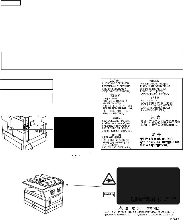
CAUTION
This product is a class 1 laser product that complies with 21CFR 1040.10 and 1040.11 of the CDRH standard and IEC60825-1 Edition 1.2-2001. This means that this machine does not produce hazardous laser radiation. The use of controls, adjustments or performance of procedures other than those specified herein may result in hazardous radiation exposure.
This laser radiation is not a danger to the skin, but when an exact focusing of the laser beam is achieved on the eye's retina, there is the danger of spot damage to the retina.
The following cautions must be observed to avoid exposure of the laser beam to your eyes at the time of servicing.
1)When a problem in the laser optical unit has occurred, the whole optical unit must be exchanged as a unit, not as individual parts.
2)Do not look into the machine with the main switch turned on after removing the developer unit, toner cartridge, and drum cartridge.
3)Do not look into the laser beam exposure slit of the laser optical unit with the connector connected when removing and installing the optical system.
4)The middle frame contains the safety interlock switch.
Do not defeat the safety interlock by inserting wedges or other items into the switch slot.
Warning:
This is a Class A product. In a domestic environment this product may cause radio interference in which case the user may be required to take adequate measures.
LUOKAN 1 LASERLAITE
KLASS 1 LASERAPPARAT
|
|
|
|
|
|
|
|
|
|
|
|
|
|
|
|
|
|
|
|
|
|
|
|
|
|
|
|
|
|
|
|
|
|
|
|
|
|
|
|
|
|
|
|
|
|
|
|
|
|
|
|
|
|
|
|
|
|
|
|
|
|
|
|
|
|
|
|
|
|
|
|
|
|
|
|
|
|
|
|
|
|
|
|
|
|
|
|
|
|
|
|
|
|
|
|
|
|
|
|
|
|
|
|
|
|
|
|
|
|
|
|
|
|
|
|
|
|
|
|
|
|
|
|
|
|
|
|
|
|
|
|
|
|
|
|
|
|
|
|
|
|
|
|
|
|
|
|
|
|
|
|
|
|
|
|
|
|
|
|
|
|
|
|
|
|
|
|
|
|
|
|
|
|
|
|
|
|
|
|
|
|
|
|
|
|
|
|
|
|
|
|
|
|
|
|
|
|
|
|
|
|
|
|
|
|
|
|
|
|
|
|
|
|
|
|
|
|
|
|
|
|
|
|
|
|
|
|
|
|
|
|
|
|
|
|
|
|
|
|
|
|
|
|
|
|
|
|
|
|
|
|
|
|
|
|
|
|
|
|
|
|
|
|
|
|
|
|
|
|
|
|
|
|
|
|
|
|
|
|
|
|
|
|
|
|
|
|
|
|
|
|
|
|
|
|
|
|
|
|
|
|
|
|
|
|
|
|
|
|
|
|
|
|
|
|
|
|
|
|
|
|
|
|
|
|
|
|
|
|
|
|
|
|
|
|
|
|
|
|
|
|
|
|
|
|
|
|
|
|
|
|
|
|
|
|
|
|
|
|
|
|
|
|
|
|
|
|
|
|
|
|
|
|
|
|
|
|
|
|
|
|
|
|
|
|
|
|
|
|
|
|
|
|
|
|
|
|
|
|
|
|
|
|
|
|
|
|
|
|
|
|
|
|
|
|
|
|
|
|
|
|
|
|
|
|
|
|
|
|
|
|
|
|
|
|
|
|
|
|
|
|
|
|
|
|
|
|
|
|
|
|
|
|
|
|
|
|
|
|
|
|
|
|
|
|
|
|
|
|
|
|
|
|
|
|
|
|
|
|
|
|
|
|
|
|
|
|
|
|
|
|
|
|
|
|
|
|
|
|
|
|
|
|
|
|
|
|
|
|
|
|
|
|
|
|
|
|
|
|
|
|
|
|
|
|
|
|
|
|
|
|
|
|
|
|
|
|
|
|
|
|
|
|
|
|
|
|
|
|
|
|
|
|
|
|
|
|
|
|
|
|
|
|
|
|
|
|
|
|
|
|
|
|
|
|
|
|
|
|
|
|
|
|
|
|
|
|
|
|
|
|
|
|
|
|
|
|
|
|
|
|
|
|
|
|
|
|
|
|
|
|
|
|
|
|
|
|
|
|
|
|
|
|
|
|
|
|
|
|
|
|
|
|
|
|
|
|
|
|
|
|
|
|
|
|
|
|
|
|
|
|
|
|
|
|
|
|
|
|
|
|
|
|
|
|
|
|
|
|
|
|
|
|
|
|
|
|
|
|
|
|
|
|
|
|
|
|
|
|
|
|
|
|
|
|
|
|
|
|
Disconnect the AC cord before servicing the unit. |
LASER WAVE - LENGTH: 785 nm + 10 nm/ 15 nm |
|
|
|
|
|
|
|
|
|
|
|
|
|
|
|
|
|
|
|
|
|
|
|
|
|
|
|
|
|||||
Pulse times : (8.141 s |
0.1 s/7 mm |
|
|
|
|
|
|
|
|
|
|
|
|
|
|
|
|
|
|
|
|
|
|
|
|
|
|
|
|
|||||
|
|
|
|
|
|
|
|
|
|
|
|
|
|
|
|
|
|
|
|
|
|
|
|
|
|
|
|
|
|
|
||||
|
|
|
Output power : 0.14 mW |
0.22 mW |
|
|
|
|
|
|
|
|
|
|
|
|
|
|
|
|
|
|
|
|
|
|
|
|
|
|
|
|
||
|
|
|
|
|
|
|
|
|
|
|
|
|
|
|
|
|
|
|
|
|
|
|
|
|
|
|
|
|
|
|
|
|
|
|
|
|
|
|
|
|
|
|
|
|
|
|
|
|
|
|
|
|
|
|
|
|
|
|
|
|
|
|
|
|
|
|
|
|
|
|
|
|
|
|
|
|
|
|
|
|
|
|
|
|
|
|
|
|
|
|
|
|
|
|
|
|
|
|
|
|
|
|
|
|
|
|
|
|
|
|
|
|
|
|
|
|
|
|
|
|
|
|
|
|
|
|
|
|
|
|
|
|
|
|
|
|
|
|
|
|
|
|
|
|
|
|
|
|
|
|
|
|
|
|
|
|
|
|
|
|
|
|
|
|
|
|
|
|
|
|
|
|
|
|
|
|
|
|
|
|
|
|
|
|
|
|
|
|
|
|
|
|
|
|
|
|
|
|
|
|
|
|
|
|
|
|
|
|
|
|
|
|
|
|
|
|
|
|
|
|
|
|
|
|
|
|
|
|
|
|
|
|
|
|
|
|
|
|
|
|
|
|
|
|
|
|
|
|
|
|
|
|
|
|
|
|
|
|
|
|
|
|
|
|
|
|
|
|
|
|
|
|
|
|
|
|
|
|
|
|
|
|
|
|
|
|
|
|
|
|
|
|
|
|
|
|
|
|
|
|
|
|
|
|
|
|
|
|
|
|
|
|
|
|
|
|
|
|
|
|
|
|
|
|
|
|
|
|
|
|
|
|
|
|
|
|
|
|
|
|
|
|
|
|
|
|
|
|
|
|
|
|
|
|
|
|
|
|
|
|
|
|
|
|
|
|
|
|
|
|
|
|
|
|
|
|
|
|
|
|
|
|
|
|
|
|
|
|
|
|
|
|
|
|
|
|
|
|
|
|
|
|
|
|
|
|
|
|
|
|
|
|
|
|
|
|
|
|
|
|
|
|
|
|
|
|
|
|
|
|
|
|
|
|
|
|
|
|
|
|
|
|
|
|
|
|
|
|
|
|
|
|
|
|
|
|
|
|
|
|
|
|
|
|
|
|
|
|
|
|
|
|
|
|
|
|
|
|
|
|
|
|
|
|
|
|
|
|
|
|
|
|
|
|
|
|
|
|
|
|
|
|
|
|
|
|
|
|
|
|
|
|
|
|
|
|
|
|
|
|
|
|
|
|
|
|
|
|
|
|
|
|
|
|
|
|
|
|
|
|
|
|
|
|
|
|
|
|
|
|
|
|
|
|
|
|
|
|
|
|
|
|
|
|
|
|
|
|
|
|
|
|
|
|
|
|
|
|
|
|
|
|
|
|
|
|
|
|
|
|
|
|
|
|
|
|
|
|
|
|
|
|
|
|
|
|
|
|
|
|
|
|
|
|
|
|
|
|
|
|
|
|
|
|
|
|
|
|
|
|
|
|
|
|
|
|
|
|
|
|
|
|
|
|
|
|
|
|
|
|
|
|
|
|
|
|
|
|
|
|
|
|
|
|
[1] GENERAL
1. Note for servicing
Pictogram
The label (
 ) in the fusing area of the machine indicates the following:
 : Caution, risk of danger
  : Caution, hot surface
A. Warning for servicing
•The fusing area is hot. Exercise care in this area when removing misfed paper.
•Do not look directly at the light source. Doing so may damage your eyes.
B. Cautions for servicing
•Do not switch the machine rapidly on and off. After turning the machine off, wait 10 to 15 seconds before turning it back on.
•Machine power must be turned off before installing any supplies. •Place the machine on a firm, level surface.
•Do not install the machine in a humid or dusty location.
•When the machine is not used for a long time, for example, during prolonged holidays, turn the power switch off and remove the power cord from the outlet.
•When moving the machine, be sure to turn the power switch off and remove the power cord from the outlet.
•Do not cover the machine with a dust cover, cloth or plastic film while the power is on. Doing so may prevent heat dissipation, damaging the machine.
•Use of controls or adjustments or performance of procedures other than those specified herein may result in hazardous laser radiation exposure.
•The socket-outlet shall be installed near the machine and shall be easily accessible.
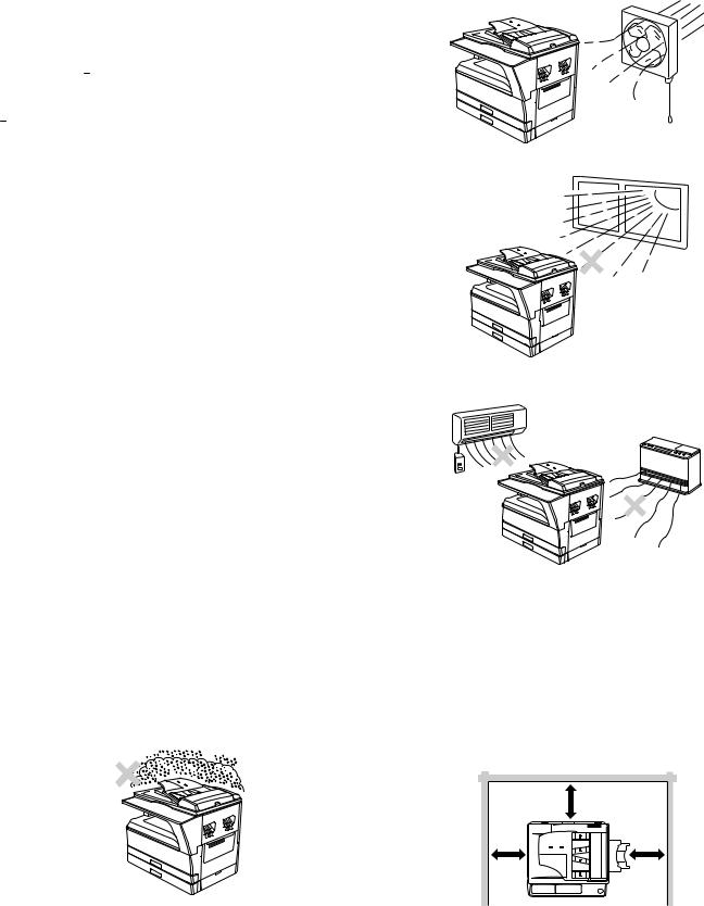
C. Note for installation place
Improper installation may damage the machine. Please note the following during initial installation and whenever the machine is moved.
Caution : If the machine is moved from a cool place to a warm place, condensation may form inside the machine. Operation in this condition will cause poor copy quality and malfunctions. Leave the machine at room temperature for at least 2 hours before use.
Do not install your machine in areas that are:
•damp, humid, or very dusty
•poorly ventilated
•exposed to direct sunlight
•subject to extreme temperature or humidity changes, e.g., near an air conditioner or heater.
The machine should be installed near an accessible power outlet for easy connection and disconnection.
Be sure to connect the power cord only to a power outlet that meets the specified voltage and current requirements. Also make certain the outlet is properly grounded.
Note : Connect the machine to a power outlet which is not used for other electric appliances. If a lighting fixture is connected to the same outlet, the light may flicker.
Be sure to allow the required space around the machine for servicing and proper ventilation.
|
20 cm (8") |
20 cm |
20 cm |
(8") |
(8") |
MX-M160 GENERAL 1-1

D. Note for handling PWB and electronic parts
When handling the PWB and the electronic parts, be sure to observe the following precautions in order to prevent against damage by static electricity.
1)When in transit or storing, put the parts in an anti-static bag or an anti-static case and do not touch them with bare hands.
2)When and after removing the parts from an anti-static bag (case), use an earth band as shown below:
• Put an earth band to your arm, and connect it to the machine.
3)When repairing or replacing an electronic part, perform the procedure on an anti-static mat.
MX-M160 GENERAL 1-2
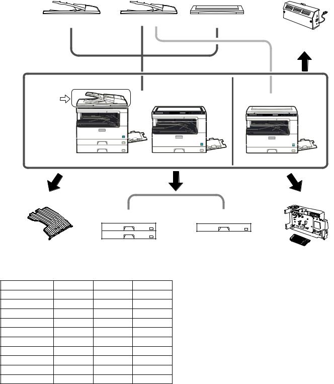
[2] CONFIGURATION
1. System Configurations
[AR-RP10] |
[AR-SP10] |
[AR-VR7] |
[MX-NB10] |
(REVERSING SINGLE PASS FEEDER) |
(SINGLE PASS FEEDER) |
(DOCUMENT COVER) |
|
|
|
|
(NEWORK PRINTING / |
|
|
|
SCANNING |
|
|
|
EXPANSION KIT) |
Standard for North America only
AR-RP10
[MX-M200D] |
[MX-M160D] |
[MX-M160] |
[MX-TR10] |
|
|
|
[MX-FX10] |
|
|
|
|
|
||
|
|
[AR-D35] |
|
[AR-D34] |
|
|
|
|
|
|
(250-sheet paper |
(JOB SEPARATOR) |
(2 x 250-sheet paper |
feed unit) |
|||
feed unit) |
|
|
(FACSIMILE |
||
|
|
|
|
||
|
|
|
|
|
EXPANSION KIT) |
2. Machine configuration |
|
|
|
|
|
|
MX-M200D |
MX-M160D |
MX-M160 |
|
|
Copy |
STD |
STD |
|
STD |
|
Color scanner |
STD |
STD |
|
STD |
|
SPLC printer |
STD |
STD |
|
STD |
|
PCL printer |
OPT |
OPT |
|
OPT |
|
Fax |
OPT |
OPT |
|
OPT |
|
Network |
OPT |
OPT |
|
OPT |
|
Duplex |
STD |
STD |
|
N/A |
|
Sort |
STD |
STD |
|
STD |
|
Shifter 1 |
STD |
STD |
|
STD |
|
Paper tray |
2-stage |
1-stage |
|
1-stage |
|
1: Except for North America
MX-M200D CONFIGURATION 2-1
3. Option list
Model name |
Name |
MX-M200D |
MX-M160D |
MX-M160 |
Product key |
|
target |
||||||
|
|
|
|
|
||
|
|
|
|
|
|
|
AR-RP10 |
REVERSING SINGLE PASS FEEDER |
North/South America: STD |
OPT |
N/A |
— |
|
|
|
Europe, Australia, Agency: OPT |
|
|
|
|
|
|
|
|
|
|
|
AR-SP10 |
SINGLE PASS FEEDER |
North/South America: N/A |
OPT |
OPT |
— |
|
|
|
Europe, Australia, Agency: OPT |
|
|
|
|
|
|
|
|
|
|
|
AR-VR7 |
DOCUMENT COVER |
North/South America:N/A |
OPT |
STD |
— |
|
|
|
Europe, Australia, Agency: OPT |
|
|
|
|
|
|
|
|
|
|
|
AR-D34 |
250-SHEET PAPER FEED UNIT |
OPT |
OPT |
OPT |
— |
|
|
|
|
|
|
|
|
AR-D35 |
2X250-SHEET PAPER FEED UNIT |
OPT |
OPT |
OPT |
— |
|
|
|
|
|
|
|
|
MX-TR10 |
JOB SEPARATOR TRAY KIT |
OPT |
OPT |
OPT |
— |
|
|
|
|
|
|
|
|
MX-NB10 |
N E WO R K P R I N T I N G / S C A N N I N G |
OPT |
OPT |
OPT |
— |
|
|
EXPANSION KIT |
|
|
|
|
|
|
|
|
|
|
|
|
MX-FX10 |
FACSIMILE EXPANSION KIT |
OPT |
OPT |
OPT |
— |
|
|
|
|
|
|
|
|
AR-SM5 |
256MB EXPANTION MEMORY BOARD |
OPT |
OPT |
OPT |
— |
|
|
|
|
|
|
|
|
AR-MM9 |
FAX EXPANTION MEMORY BOARD |
OPT |
OPT |
OPT |
— |
|
|
|
|
|
|
|
|
AR-PF1 |
BARCODE FONT KIT |
OPT |
OPT |
OPT |
— |
|
|
|
|
|
|
|
|
MX-PK10 |
PS3 EXPANSION KIT |
OPT |
OPT |
OPT |
Yes |
|
|
|
|
|
|
|
|
AR-PF2 |
MACRO FONT FLASH ROM KIT |
OPT |
OPT |
OPT |
— |
|
|
|
|
|
|
|
O: Option installation enable X: Option installation disable
MX-M200D CONFIGURATION 2-2
[3] SPECIFICATIONS
1. Copy mode
A. Type
Type |
Desk-top |
|
|
Paper exit |
center tray / internal |
|
|
B. Machine composition
MX-M160D/MX-M160 |
16-CPM multi function model |
|
|
MX-M200D |
20-CPM multi function model |
|
|
C. Copy speed
(1) Engine speed (ppm)
Paper size |
MX-M200D |
MX-M160D/MX-M160 |
|
|
|
A4/ 8.5”x11” |
20ppm |
16ppm |
|
|
|
A4R |
14ppm |
12ppm |
|
|
|
8.5”x11”R |
15ppm |
12ppm |
|
|
|
A5/ 5.5”x8.5” |
20ppm |
16ppm |
|
|
|
B5/ 16K |
20ppm |
16ppm |
|
|
|
B5R |
16ppm |
14ppm |
|
|
|
16KR |
15ppm |
14ppm |
|
|
|
8.5x13” |
12ppm |
11ppm |
|
|
|
B4/ 8.5”x14 |
12ppm |
10ppm |
|
|
|
A3 |
11ppm |
9ppm |
|
|
|
11”x17” |
10ppm |
9ppm |
|
|
|
8K |
11ppm |
10ppm |
|
|
|
(2) Document replacement speed (Copy mode)
Copy mode |
MX-M200D |
MX-M160D/MX-M160 |
||
|
|
|
|
|
S to S |
20cpm |
(100%) |
16cpm |
(100%) |
|
|
|
|
|
S to S : Tray1 A4/8.5”X11” document 11 sheets (11 pages), copy 1 set
(3) Job efficiency
Copy mode |
MX-M200D |
MX-M160D |
MX-M160 |
||
|
|
|
|
||
S to S |
18cpm (90%) |
15cpm (49%) |
15cpm (94%) |
||
|
|
|
|
|
|
S to D |
10cpm |
(50%) |
10cpm |
(63%) |
— |
|
|
|
|
|
|
D to D |
10cpm |
(50%) |
10cpm |
(63%) |
— |
|
|
|
|
|
|
S to S : Tray1 A4/8.5”X11” document 10 sheets (10 pages), copy 5 sets S to D : Tray1 A4/8.5”X11” document 10 sheets (10 pages), copy 5 sets D to D : Tray1 A4/8.5”X11” document 10 sheets (20 pages), copy 5 sets
(4) First copy time
Tray |
Content |
|
|
1st tray |
7.2 sec or less |
|
|
2nd tray |
8.5 sec or less |
|
|
3rd tray |
9.5 sec or less |
|
|
4th tray |
10.5 sec or less |
|
|
Bypass tray |
7.5 sec or less |
|
|
600x300dpi, AE mode, A4/Letter, single surface copy with OC, in polygon ready state
D. Document
Max. document size |
A3, 11" X 17" |
|
|
Document reference position |
Left bottom reference |
|
|
Detection (Platen) |
Yes |
|
|
E. Paper feed
(1) Paper feed section details
Item |
|
1st tray |
2nd tray |
Bypass tray |
|
|
|
|
|
Paper capacity |
|
250 |
250 |
100 sheets |
|
|
sheets |
sheets |
|
|
|
|
|
|
Paper size detection |
|
|
No |
|
|
|
(Paper size is set with |
||
|
|
the system setting.) |
||
|
|
|
|
|
Paper type setting |
|
No |
No |
No |
|
|
|
|
(Heavy |
|
|
|
|
paper setting |
|
|
|
|
is enabled.) |
|
|
|
|
|
Paper size changing method |
The paper guide is set by the user. |
|||
|
|
|
|
|
Paper when shipping |
AB series |
A4 |
A4 |
- |
|
|
|
|
|
Size setting |
Inch series |
8 1/2” x11” |
8 1/2” x11” |
- |
|
|
|
|
|
Remaining paper quantity |
Only empty detection available |
|||
detection |
|
|
|
|
|
|
|
|
|
(2) Feedable paper
Paper size |
|
1st tray |
2nd tray |
Bypass |
|
|
|
|
tray |
A3 |
297x420 |
Yes |
Yes |
Yes |
|
|
|
|
|
B4 |
257x364 |
Yes |
Yes |
Yes |
|
|
|
|
|
A4 |
297x210 |
Yes |
Yes |
Yes |
|
|
|
|
|
A4-R |
210x297 |
Yes |
Yes |
Yes |
|
|
|
|
|
B5 |
257x182 |
Yes |
Yes |
Yes |
|
|
|
|
|
B5R |
182x257 |
Yes |
Yes |
Yes |
|
|
|
|
|
A5 |
210x148.5 |
Yes |
N/A |
Yes |
|
|
|
|
|
A5R |
148.5x210 |
N/A |
N/A |
Yes |
|
|
|
|
|
A6R |
105x148.5 |
N/A |
N/A |
Yes |
|
|
|
|
|
B6R |
128.5x182 |
N/A |
N/A |
Yes |
|
|
|
|
|
Ledger 11 x 17 in |
279.4x431.8 |
Yes |
Yes |
Yes |
|
|
|
|
|
Legal 8.5x14in. |
215.9x355.6 |
Yes |
Yes |
Yes |
|
|
|
|
|
Foolscap 8.5 x 13 in |
215.9x330.2 |
Yes |
Yes |
Yes |
|
|
|
|
|
Letter 11x8.5in |
279.4x215.9 |
Yes |
Yes |
Yes |
|
|
|
|
|
Letter-R 8.5x11in |
215.9x279.4 |
Yes |
Yes |
Yes |
|
|
|
|
|
Executive-R 7.25x10.5in. |
184.2x266.7 |
N/A |
N/A |
Yes |
|
|
|
|
|
Invoice 8.5x5.5 in. |
215.9x139.7 |
Yes |
N/A |
Yes |
|
|
|
|
|
Invoice-R 5.5x8.5 in |
139.7x215.9 |
N/A |
N/A |
Yes |
|
|
|
|
|
8K |
270x390 |
Yes |
Yes |
Yes |
|
|
|
|
|
16K |
270x195 |
Yes |
Yes |
Yes |
|
|
|
|
|
16KR |
195x270 |
Yes |
Yes |
Yes |
|
|
|
|
|
COM10 |
104.8x241.3 |
N/A |
N/A |
Yes |
|
|
|
|
|
COM9 |
98.4x225.4 |
N/A |
N/A |
Yes |
|
|
|
|
|
C5 |
162x229 |
N/A |
N/A |
Yes |
|
|
|
|
|
DL |
110x220 |
N/A |
N/A |
Yes |
|
|
|
|
|
Postcard |
100x148 |
N/A |
N/A |
Yes |
|
|
|
|
|
Return postcard |
200x148 |
N/A |
N/A |
Yes |
|
|
|
|
|
Long format No. 3 |
120.1x235 |
N/A |
N/A |
Yes |
|
|
|
|
|
Monarch |
98.4x190.5 |
N/A |
N/A |
Yes |
|
|
|
|
|
Western format No. 2 |
114x162 |
N/A |
N/A |
Yes |
|
|
|
|
|
Western format No. 4 |
105x235 |
N/A |
N/A |
Yes |
|
|
|
|
|
MX-M200D SPECIFICATIONS 3-1
(3)Types of feedable paper
Types of paper |
1st tray |
2nd tray |
Bypass tray |
||
|
|
|
|
|
|
Thin paper |
56-59g/m2 |
Yes |
Yes |
Yes |
|
15-15.9lbs |
|||||
|
|
|
|
||
|
|
|
|
|
|
|
60-90g/m2 |
|
|
Yes |
|
Plain paper |
Yes |
Yes |
(Multi paper |
||
16-24lbs |
|||||
|
|
|
feed enable) |
||
|
|
|
|
||
|
|
|
|
|
|
|
91-105g/m2 |
|
|
Yes |
|
Heavy paper |
N/A |
N/A |
(Multi paper |
||
16-24lbs |
|||||
|
|
|
feed enable) |
||
|
|
|
|
||
|
|
|
|
|
|
|
|
|
|
Yes |
|
Heavy paper |
106-128g/m2 |
N/A |
N/A |
(A4 or less) |
|
24.1-33.5lbs |
(Multi paper |
||||
|
|
|
|||
|
|
|
|
feed enable) |
|
|
|
|
|
|
|
|
|
|
|
Yes |
|
Heavy paper |
129-200g/m2 |
N/A |
N/A |
(A4 or less) |
|
33.6-53.2lbs |
(Only single |
||||
|
|
|
|||
|
|
|
|
paper feed) |
|
|
|
|
|
|
|
Heavy paper |
201-256g/m2 |
N/A |
N/A |
N/A |
|
53.3-68lbs |
|||||
|
|
|
|
||
|
|
|
|
|
|
Envelope |
75-90g/m2 |
N/A |
N/A |
Yes |
|
20-24lbs |
|||||
|
|
|
|
||
|
|
|
|
|
|
Postcard |
|
N/A |
N/A |
Yes |
|
|
|
|
|
|
|
OHP film |
|
N/A |
N/A |
Yes |
|
|
|
|
|
|
|
Label sheet |
|
N/A |
N/A |
Yes |
|
|
|
|
|
|
|
Tab paper 20 |
|
N/A |
N/A |
No |
|
|
|
|
|
|
|
F. Multi copy
Max. number of |
999 sheets |
multi copy |
|
|
|
G. Warm-up time
Warm-up time |
45 seconds or less |
|
|
Pre-heat |
Available |
|
|
Jam recovery |
Within 45 sec |
|
|
H. Copy magnification ratio
Fixed |
AB system: |
magnification |
400, 200, 141, 122, 115, 100, 86, 81, 70, 50, 25% |
ratio |
|
Inch system: |
|
|
400, 200, 141, 129, 121, 100, 95, 77, 64, 50, 25% |
|
|
Zooming |
25 ~ 400% |
|
SPF/RSPF(50 ~ 200%) |
|
|
Independent |
Available (25 ~ 400%) |
zooming(vertical) |
SPF/RSPF(50 ~ 200%) |
|
|
Independent |
Available (25 ~ 400%) |
zooming |
SPF/RSPF(50 ~ 200%) |
(horizontal) |
|
|
|
I. Print density
Density mode |
Auto / Text / Photo |
|
|
|
|
No. of manual |
5 steps (Text / Photo) |
|
adjustment |
|
|
|
|
|
Resolution |
Writing: 600 x 600dpi |
|
|
Reading: 600 |
(main) x 600 (sub) (PHOTO mode) |
|
600 |
(main) x 300 (sub) (AUTO exposure |
|
mode) |
|
|
600 |
(main) x 300 (sub) dpi (TEXT mode) |
|
|
|
Gradation |
Reading: 256 gradations |
|
|
Writing: Binary |
|
|
|
|
Toner save mode |
Set by the user program |
|
|
|
|
J. Void width
Void area |
Lead edge 1 ~ 4mm, |
|
rear edge 4mm or less, |
|
Total of both sides: 6mm or less |
|
|
Image loss |
4.0mm or less |
|
|
K. Paper exit / finishing
Paper exit section |
Face down 250 sheets |
capacity |
|
|
|
Full detection |
Detection of 250 sheets count is for only copy mode |
|
When the job separator is installed, only detection |
|
is available |
|
Upper stage: 100 sheets or 10.6mm or less |
|
Lower stage: 150 sheets |
|
|
Finishing |
Shifter (Standard except for North America) |
|
Job separator (Option) |
|
|
Electronic sort |
A4/ 8.5" x 11" standard document (6% coverage) |
capacity |
160 sheets |
|
|
Offset function |
Yes (Except for North America) |
|
|
Staple function |
None |
|
|
L. Additional functions
APS |
|
O |
|
|
|
AMS |
|
O |
|
|
|
Auto tray switching |
|
O |
|
|
|
Memory copy |
|
O |
|
|
|
Rotation copy |
|
O |
|
|
|
E-sort |
O |
Single surface, A4, Max. 80 sheets |
(Sorting function) |
|
|
|
|
|
E-sort (Grouping |
|
O |
function) |
|
|
|
|
|
|
|
|
Rotation sort |
|
X |
|
|
|
Prevention of sky |
|
X |
shot |
|
|
|
|
|
|
|
|
Independent |
|
O |
zooming |
|
|
|
|
|
|
|
|
1 set 2 copy |
O SPF: Disable |
|
|
|
OC: Enlargement is disable. |
|
|
|
Binding margin |
O |
Default AB series: 10mm (5, 10, 15, 20mm) |
|
|
Inch series: 1/2 inch (1/4, 1/2, 3/4, 1 inch) |
|
|
|
Edge erase |
O |
Default AB series: 10mm (5, 10, 15, 20mm) |
|
|
Inch series: 1/2 inch (1/4, 1/2, 3/4, 2 inch) |
|
|
|
Center erase |
O |
Default AB series: 10mm (5, 10, 15, 20mm) |
|
|
Inch series: 1/2 inch (1/4, 1/2, 3/4, 3 inch) |
|
|
|
Black/white |
|
X |
reverse |
|
|
|
|
|
|
|
|
Multi shot |
|
O |
|
|
|
Offset |
|
X |
|
|
|
Preheating |
O |
The conditions are set by the user program. |
|
|
|
Auto shut-off |
O |
The conditions are set by the user program. |
|
|
|
User programming |
|
O |
|
|
|
Total counter |
O |
Supports Total counter and Copy counter and |
|
|
Scanner counter. |
|
|
|
Coin vendor |
O |
(Supports I/F only.) |
support |
|
|
|
|
|
Auditor support |
O |
(Supports I/F only.) |
|
|
|
Toner save |
O |
(Set according to the destination) |
|
|
|
Department |
O |
(Total of copy, printer, and scanner: 50 Dept., |
management |
|
Fax: 50 Dept.) |
|
|
|
O : Available X : Not available
MX-M200D SPECIFICATIONS 3-2
M. Other specifications
Photoconductor type |
OPC (Organic Photo Conductor) |
|
|
Photoconductor drum dia. |
30mm |
|
|
Copy lamp |
Cold cathode fluorescent lamp (CCFL) |
|
|
Developing system |
Dry 2-component magnetic brush |
|
development |
|
|
Charging system |
Saw teeth charging |
|
|
Transfer system |
(+) DC corotron |
|
|
Separation system |
(-) DC corotron |
|
|
Fusing system |
Heat roller |
|
|
Cleaning system |
Contact blade |
|
|
N. Package form
Body |
Body / Accessories |
|
|
O. External view
|
MX-M200D |
MX-M160D |
|
MX-M160 |
|
|
|
|
|
External |
590 mm(W) x |
590 mm (W) x |
|
590 mm (W) x |
dimensions |
574 mm(D) x |
574 mm (D) x |
|
574 mm (D) x |
(With the bypass |
522 mm(H) |
437 mm (H) |
|
470 mm (H) |
tray closed) |
(Except for North |
|
|
|
|
America) |
|
|
|
|
651 mm(H) |
|
|
|
|
(For North America) |
|
|
|
|
|
|
|
|
Occupying area |
|
|
|
|
(With the bypass |
883mm(W) x 574mm(D) |
|
||
tray opened) |
|
|
|
|
|
|
|
|
|
Weight |
33.0Kg |
|
|
|
(Excluding |
(Except for North |
|
|
|
developer) |
America) |
28.1Kg |
|
29.7Kg |
|
38.3Kg |
|
|
|
|
(For North America) |
|
|
|
|
|
|
|
|
P. Power source
Voltage |
100 - 127V 220 - 240V |
|
|
Frequency |
50/60Hz common |
|
|
Q. Power consumption
Max. power consumption |
1200W |
|
|
|
|
* EnergyStar conformity |
|
|
|
|
|
Power consumption when |
10W (Not including option) |
|
standby |
|
|
|
|
|
R. Digital performance |
|
|
|
|
|
Resolution |
Reading |
600 x 600dpi (PHOTO mode) |
|
|
600 x 300dpi (AUTO exposure mode) |
|
|
600 (main) x 600 (sub) dpi (TEXT mode) |
|
|
|
|
Writing |
600 x 600dpi |
|
|
|
Gradation |
Reading |
256 gradations |
|
|
|
|
Writing |
Binary |
|
|
|
Memory |
64MB |
|
|
|
|
Hard disk |
None |
|
|
|
|
S. Printing function
(1) Platform
Item |
Content |
|
|
Support platform |
IBM PC/AT compatible machine |
|
|
(2) Support OS
|
OS |
SPLC |
PCL6 |
PCL5e |
PS |
PPD |
Rerease |
|
SPDL2 |
method |
|||||
|
|
|
|
|
|
|
|
Windows |
98/Me |
No |
No |
No |
No |
No |
|
|
|
|
|
|
|
|
|
|
NT 4.0 SP5 or |
No |
No |
No |
No |
No |
|
|
later |
|
|
|
|
|
|
|
|
|
|
|
|
|
|
|
2000 |
Yes |
Yes |
Yes |
Yes |
Yes |
CD-ROM |
|
|
|
|
|
|
|
|
|
XP |
Yes |
Yes |
Yes |
Yes |
Yes |
CD-ROM |
|
|
|
|
|
|
|
|
|
XP x64 |
Yes |
Yes |
No |
Yes |
Yes |
Web |
|
|
|
|
|
|
|
|
|
Server 2003 |
No |
Yes |
Yes |
Yes |
Yes |
CD-ROM |
|
|
|
|
|
|
|
|
|
Server 2003 |
No |
Yes |
No |
Yes |
Yes |
Web |
|
x64 |
|
|
|
|
|
|
|
|
|
|
|
|
|
|
|
Vista |
Yes |
Yes |
Yes |
Yes |
Yes |
CD-ROM |
|
|
|
|
|
|
|
|
|
Vista x64 |
Yes |
Yes |
No |
Yes |
Yes |
Web |
|
|
|
|
|
|
|
|
|
Server 2008 |
No |
Yes |
No |
Yes |
Yes |
CD-ROM |
|
|
|
|
|
|
|
|
|
Server 2008 |
No |
Yes |
No |
Yes |
Yes |
Web |
|
x64 |
|
|
|
|
|
|
|
|
|
|
|
|
|
|
Mac |
9.0-9.2.2 |
No |
No |
No |
No |
Yes |
CD-ROM |
|
|
|
|
|
|
|
|
|
X 10.2.8 |
No |
No |
No |
No |
Yes |
CD-ROM |
|
|
|
|
|
|
|
|
|
X 10.3.9 |
No |
No |
No |
No |
Yes |
CD-ROM |
|
|
|
|
|
|
|
|
|
X 10.4.11 |
No |
No |
No |
No |
Yes |
CD-ROM |
|
|
|
|
|
|
|
|
|
X 10.5-10.5.6 |
No |
No |
No |
No |
Yes |
CD-ROM |
|
|
|
|
|
|
|
|
(3) Printer driver function (SPLC)
|
Item |
|
SPLC |
|
|
|
|
Common |
Custom settings |
Yes |
|
|
|
|
|
|
Reset to default |
Yes |
|
|
|
|
|
|
MIMIC |
|
Yes |
|
|
|
|
Configuration |
Paper feed option |
Tray1/ Tray2/ Tray3/ Tray4 |
|
|
|
|
|
|
Tray |
Paper tray |
Tray1/ Tray2/ Tray3/ Tray4/ |
|
Settings |
|
Manual paper feed |
|
|
|
|
|
|
Set Paper |
Not set/ A3/ A4-R/ A5-R/ A6/ B4/ |
|
|
size |
B5-R/ B6/ Ledger/ Letter-R/ Legal/ |
|
|
|
Executive/ Invoice-R/ Foolscap/ |
|
|
|
Folio/ Com10/ DL/ C5/ 8k/ 16k-R/ |
|
|
|
Custom paper |
|
|
|
|
|
Status window |
Yes |
|
|
|
|
|
|
Version information |
Yes |
|
|
|
|
|
Main |
Number of copies |
1-999 |
|
|
|
|
|
|
Print in the unit of |
On/ Off |
|
|
copies |
|
|
|
|
|
|
|
N-UP printing |
1/ 2/ 4 /6 up |
|
|
|
|
|
|
frame line |
On/ Off |
|
|
|
|
|
|
Order |
|
From left to right */ From right to |
|
|
|
left */ From top to bottom */ From |
|
|
|
top right to downward **/ From top |
|
|
|
left to right **/ From top right to left |
|
|
|
**/ From top right to downward ** |
|
|
|
(“*” is displayed for 2UP only. |
|
|
|
“**” is displayed except for 1UP |
|
|
|
and 2UP.) |
|
|
|
|
|
Print direction |
Vertical/Horizontal |
|
|
|
|
|
|
Print after rotating |
Yes |
|
|
180°C |
|
|
|
|
|
|
MX-M200D SPECIFICATIONS 3-3
|
Item |
|
SPLC |
|
|
|
|
Paper |
Paper size |
A3/ A4/ A5/ A6/ B4/ B5/ B6/ |
|
|
|
|
Ledger/ Letter/ Legal/ Executive/ |
|
|
|
Invoice/ Foolscap/ Folio/ Com10/ |
|
|
|
DL/ C5/ 8k/ 16k/ Custom page |
|
|
|
|
|
|
|
- Custom paper: |
|
|
|
Width [100.0] -[297.0] |
|
|
|
[3.94”] -[11.69”] |
|
|
|
Length [148.0] -[431.8] |
|
|
|
[5.83”] - [17.00”] |
|
|
|
- Milimeters/ Inches |
|
|
|
|
|
Setting for zoom |
None/ Fit page printing/ zoom |
|
|
|
|
(“24” - “400”) |
|
|
|
|
|
Setting |
|
Yes |
|
|
|
|
|
Paper feed system |
Auto paper feed/ manual feed/ |
|
|
|
|
Tray1/ Tray2/ Tray3/ Tray4 |
|
|
|
|
Advanced |
Image |
brightness |
“0” - “100” |
setting |
adjust- |
|
|
Contrast |
“0” - “100” |
||
|
ment |
|
|
|
|
|
|
|
Print text in black |
On/ Off |
|
|
|
|
|
|
Print line in black |
On/ Off |
|
|
|
|
|
Advanced |
Compati |
Input |
300dpi/ 600dpi |
setting |
-bility |
resolution |
|
|
|
|
|
|
|
Hatching |
Standard/Fine |
|
|
pattern |
|
|
|
|
|
|
|
Spool type |
RAW/ EMF |
|
|
|
|
|
|
Reduction |
Standard/Unit of page/Unit of object |
|
|
system |
|
|
|
|
|
|
|
“1” - “5” |
|
|
|
density |
|
|
|
adjustment |
|
|
|
|
|
|
|
Priority on |
On/ Off |
|
|
the driver |
|
|
|
setting - |
|
|
|
Print in the |
|
|
|
unit of |
|
|
|
copies |
|
|
|
|
|
|
|
Priority on |
On/ Off |
|
|
the driver |
|
|
|
setting - |
|
|
|
Duplex |
|
|
|
|
|
|
|
|
|
Watermark |
Watermark |
Top secret/ Confidential/ Draft/ |
|
|
|
|
Original/ Copy |
|
|
|
|
|
Position |
|
X: [-50] - [50] |
|
|
|
Y: [-50] - [50] |
|
|
|
Sets to the center position. |
|
|
|
|
|
Size |
|
“6” - “300” |
|
|
|
|
|
Angle |
|
“-90” - “90” |
|
|
|
|
|
Edit |
Font name |
|
|
|
|
|
|
|
Bold text |
On/ Off |
|
|
|
|
|
|
Italic face |
On/ Off |
|
|
|
|
|
|
Text set |
It depends on the font name. |
|
|
|
|
|
|
Color |
“0” - “255” |
|
|
density |
|
|
|
|
|
|
Print the first page |
On/ Off |
|
|
only |
|
|
|
|
|
|
T. Scanner function
Type |
Flat bed scanner |
|
|
Scan system |
Document table/document feed unit |
|
|
Light source |
White CCFL |
|
|
Resolution |
Color: 600 x 600dpi |
|
B/W: 600 x 300dpi (Default) |
|
600 x 600dpi |
|
|
Document |
Sheet/Book |
|
|
Effective scan range |
OC/SPF/RSPF: |
|
about 297(length) x 431(width) mm |
|
|
Scan speed |
OC/SPF/R-SPF: |
|
0.962msec/line(300 dpi) |
|
|
Input data |
1bit or 12bit |
|
|
Output data |
1bit or 8bit |
|
|
Scan color |
B/W(Simple binary) / B/W(error diffusion) / |
|
Gray scale / Full color |
|
|
Protocol |
TWAIN/WIA(XP,Vista)/STI |
|
|
Interface |
USB2 |
|
|
Scanner utility |
Button Manager/Sharpdesk |
|
|
Drop-out color |
Yes (Red/Green/Blue/White) |
|
|
Scanner button |
Provided (6) |
|
|
Supported OS |
Windows 2000/XP/VISTA |
|
|
Void area |
Lead edge/rear edge (2.5mm) on the driver |
|
side Left/right: 3.0mm |
|
|
WHQL support |
Support by running change |
|
|
MX-M200D SPECIFICATIONS 3-4
[4] CONSUMABLE PARTS
1.Supply system table
A. USA/Canada
MX-M200D
No. |
Name |
Product name |
Content |
|
Life |
Remark |
|
|
|
|
|
|
|
1 |
Toner cartridge |
MX-206NT |
Toner cartridge |
x1 |
16K |
Life setting by A4 6% document |
|
|
|
(Toner:Net 547g With IC) |
|
|
|
|
|
|
|
|
|
|
2 |
Developer |
AR-205MD |
Developer |
x10 |
500K |
|
|
|
|
(Net 300g) |
|
(50x10) |
|
|
|
|
|
|
|
|
3 |
Drum KIT |
AR-205DR |
Drum |
x1 |
50K |
|
|
|
|
Drum fixing plate |
x1 |
|
|
|
|
|
|
|
|
|
B. South and Central America (200V series)
MX-M160/MX-M160D/MX-M200D
No. |
Name |
Product name |
Content |
|
Life |
Remark |
|
|
|
|
|
|
|
1 |
Toner cartridge |
MX-206GT |
Toner cartridge |
x1 |
19K |
Life setting by A4 6% document |
|
|
|
(Toner:Net 547g With IC) |
|
|
(In a toner save mode) |
|
|
|
|
|
|
|
2 |
Developer |
AR-205LD |
Developer |
x10 |
500K |
|
|
|
|
(Net 300g) |
|
(50x10) |
|
|
|
|
|
|
|
|
3 |
Drum KIT |
AR-205DM |
Drum |
x1 |
50K |
|
|
|
|
Drum fixing plate |
x1 |
|
|
|
|
|
|
|
|
|
C. Europe
MX-M160D/MX-M200D
No. |
Name |
Product name |
Content |
|
Life |
Remark |
|
|
|
|
|
|
|
1 |
Toner cartridge |
MX-206GT |
Toner cartridge |
x1 |
16K |
Life setting by A4 6% document |
|
|
|
(Toner:Net 547g With IC) |
|
|
|
|
|
|
|
|
|
|
2 |
Developer |
AR-205LD |
Developer |
x10 |
500K |
|
|
|
|
(Net 300g) |
|
(50x10) |
|
|
|
|
|
|
|
|
3 |
Drum KIT |
AR-205DM |
Drum |
x1 |
50K |
|
|
|
|
Drum fixing plate |
x1 |
|
|
|
|
|
|
|
|
|
D. Australia/New Zealand
MX-M160/MX-M160D/MX-M200D
No. |
Name |
Product name |
Content |
|
Life |
Remark |
|
|
|
|
|
|
|
1 |
Toner cartridge |
MX-206GT |
Toner cartridge |
x1 |
16K |
Life setting by A4 6% document |
|
|
|
(Toner:Net 547g With IC) |
|
|
|
|
|
|
|
|
|
|
2 |
Developer |
AR-205LD |
Developer |
x10 |
500K |
|
|
|
|
(Net 300g) |
|
(50x10) |
|
|
|
|
|
|
|
|
3 |
Drum KIT |
AR-205DM |
Drum |
x1 |
50K |
|
|
|
|
Drum fixing plate |
x1 |
|
|
|
|
|
|
|
|
|
E. Middle East/Africa/Israel/Palestine/Philippine/Taiwan
MX-M160/MX-M160D/MX-M200D
No. |
Name |
Product name |
Content |
|
|
Life |
|
|
|
|
|
|
|
1 |
Toner cartridge |
MX-206FT |
Toner cartridge |
x1 |
16K |
Life setting by A4 6% document |
|
|
|
(Toner:Net 547g With IC) |
|
|
|
|
|
|
|
|
|
|
2 |
Developer |
AR-205CD |
Developer |
x10 |
500K |
|
|
|
|
(Net 300g) |
|
(50x10) |
|
|
|
|
|
|
|
|
3 |
Drum KIT |
AR-205DR |
Drum |
x1 |
50K |
|
|
|
|
Drum fixing plate |
x1 |
|
|
|
|
|
|
|
|
|
F. Asia (Except the above)
MX-M160/MX-M160D/MX-M200D
No. |
Name |
Product name |
Content |
|
Life |
Remark |
|
|
|
|
|
|
|
1 |
Toner cartridge |
MX-206AT |
Toner cartridge |
x1 |
16K |
Life setting by A4 6% document |
|
|
|
(Toner:Net 547g With IC) |
|
|
|
|
|
|
|
|
|
|
2 |
Developer |
AR-205CD |
Developer |
x10 |
500K |
|
|
|
|
(Net 300g) |
|
(50x10) |
|
|
|
|
|
|
|
|
3 |
Drum KIT |
AR-205DR |
Drum |
x1 |
50K |
|
|
|
|
Drum fixing plate |
x1 |
|
|
|
|
|
|
|
|
|
MX-M200D CONSUMABLE PARTS 4-1
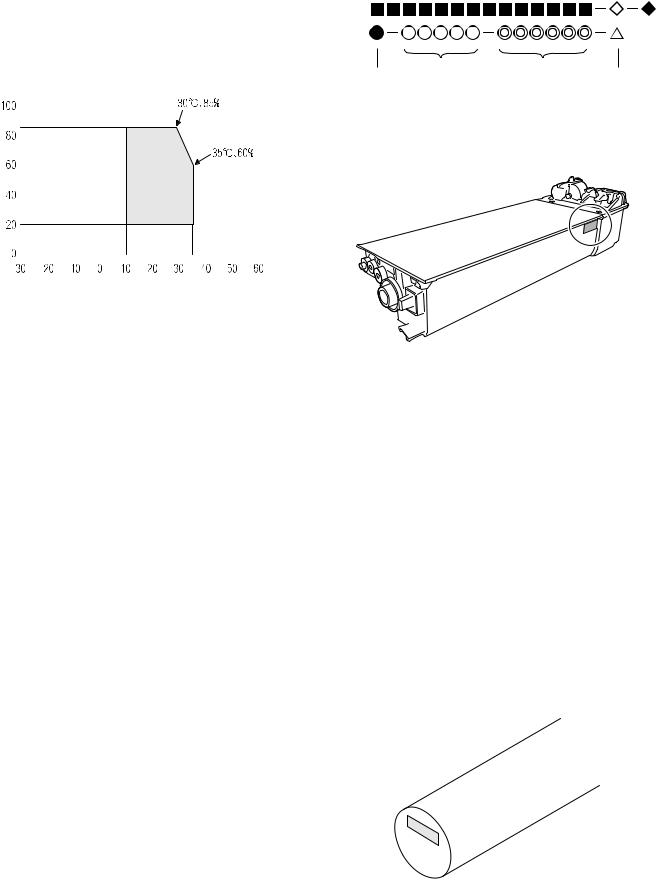
2. Environmental conditions
A. Transport conditions
(1) Transport conditions
-20°C - 45°C (No condensation)
(2) Storage conditions
-10°C - 40°C (Unopened, No condensation)
B. Use conditions
(%) |
|
|
|
|
|
Use envi- |
|||||
|
|
|
|
|
|||||||
|
|||||||||||
Humidity |
|
|
|
|
|
ronment |
|||||
|
|
|
|
|
|
||||||
|
|
|
|
|
|
conditions |
|||||
|
|
||||||||||
|
|
|
|
|
|
|
|
|
|
|
|
|
|
|
|
|
|
|
|
|
|
|
|
|
|
|
|
|
|
|
|
|
|
|
|
Temperature 

C. Life(packed conditions)
Photoconductor drum (36 months from the production month) Developer, toner (24 months from the production month)
3. Production number identification
<Toner cartridge>
The label on the toner cartridge shows the date of production.
Production |
Serial |
Year/ |
Ver.No. |
place |
number |
Month/ |
|
|
|
Day |
|
<Drum cartridge>
The lot number, printed on the front side flange, is composed of 6 digits, each digit showing the following content:
1 |
2 |
3 |
4 |
5 |
6 |
1Alphabet
Indicates the model conformity code. A for this model.
2Number
Indicates the end digit of the production year.
3Number or X, Y, Z
Indicates the month of packing.
X stands for October, Y November, and Z December.
4/5 Number
Indicates the day of the month of packing.
6Alphabet
Indicates the production factory. "A" for Nara Plant, “C“ for SOCC
MX-M200D CONSUMABLE PARTS 4-2
[5] EXTERNAL VIEWS AND INTERNAL STRUCTURES
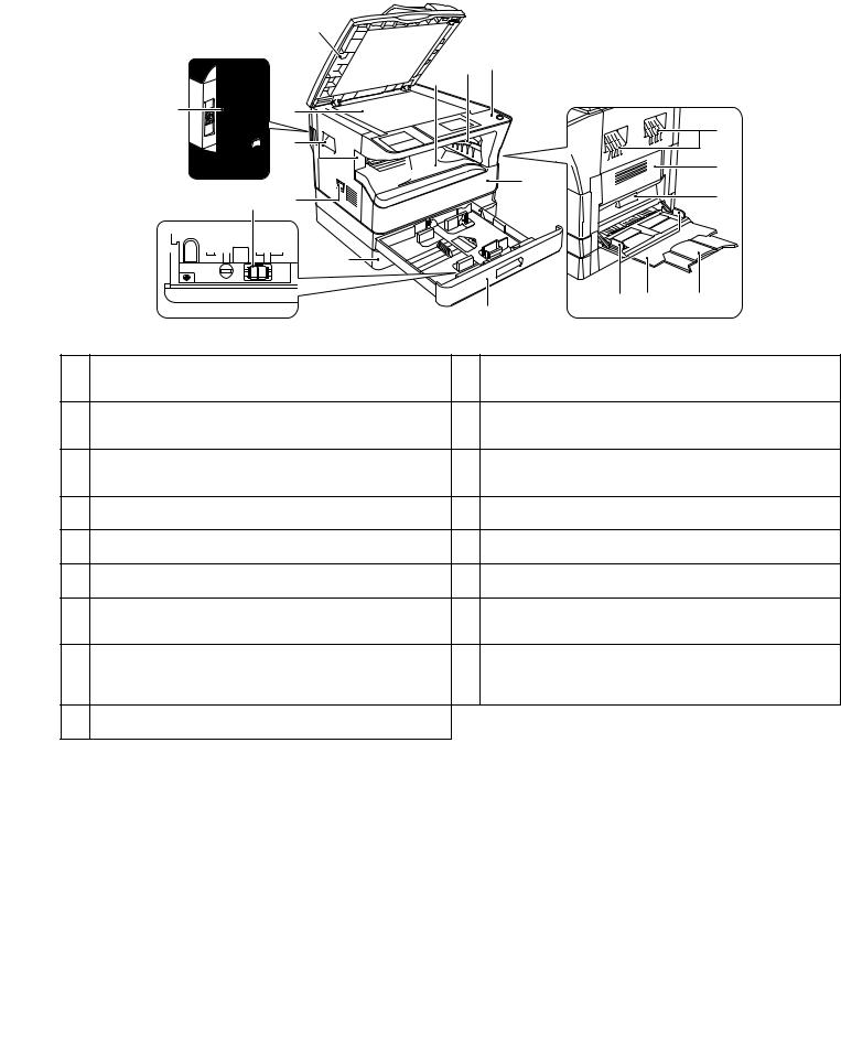
1. Appearance
|
|
3 |
|
|
|
|
|
|
|
|
7 |
8 |
9 |
|
|
|
|
|
|
|
|
|
|
|
1 |
4 |
|
|
|
|
5 |
|
|
5 |
|
|
|
|
|
|
|
|
|
|
|
|
|
|
|
|
|
|
10 |
|
13 |
|
2 |
6 |
|
|
|
14 |
|
|
|
|
|
|
|||
|
|
|
12 |
|
|
|
|
|
|
|
|
|
15 |
16 |
17 |
|
|
|
|
|
11 |
|
|
1 |
USB 2.0 port |
|
|
10 |
Front cover |
|
|
|
Connect to your computer to this port to use the printer and scanner |
|
Open to remove paper misfeeds or replace the toner cartridge. |
||||
|
functions. |
|
|
|
|
|
|
2 |
Charger cleaner |
|
|
11 |
Tray 1 |
|
|
|
Use to clean the transfer charger. |
|
|
|
Tray 1 can hold approximately 250 sheets of copy paper (20 lbs. (80 |
||
|
|
|
|
|
g/m2 )). |
|
|
3 |
Glass cleaner |
|
|
12 |
Tray 2 |
|
|
|
Use to clean the original scanning glass. |
|
|
Tray 2 can hold approximately 250 sheets of copy paper (20 lbs. (80 |
|||
|
|
|
|
|
g/m2 )). |
|
|
4 |
Document glass |
|
|
13 |
Side cover |
|
|
|
Place an original that you wish to scan face |
down here. |
|
Open to remove misfed paper. |
|
||
5 |
Handles |
|
|
14 |
Side cover handle |
|
|
|
Use to move the machine. |
|
|
|
Pull to open the side cover. |
|
|
6 |
Power switch |
|
|
15 |
Bypass tray guides |
|
|
|
Press to turn the machine power on and off. |
|
|
Adjust to the width of the paper when using the bypass tray. |
|||
7 |
Center tray |
|
|
16 |
Bypass tray |
|
|
|
Copies and printed pages are output to this |
tray. |
|
Special paper (heavy paper or transparency film) can be fed from |
|||
|
|
|
|
|
the bypass tray. |
|
|
8 |
Top tray |
|
|
17 |
Bypass tray extension |
|
|
|
(when the job separator tray kit is installed) |
|
Pull out when feeding large paper such as 11" x 17" and 8-1/2" x 14" |
||||
|
Received faxes (when the fax option is installed) and print jobs are |
|
(A3 and B4). |
|
|
||
|
delivered to this tray. |
|
|
|
|
|
|
9Operation panel
Contains operation keys and indicator lights.
MX-M200D EXTERNAL VIEWS AND INTERNAL STRUCTURES 5-1
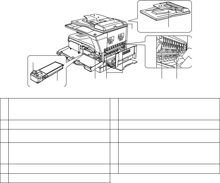
2. Internal
20 21 |
22 |
|||
|
|
|
|
|
|
|
|
|
|
|
|
|
|
|
|
|
|
|
|
23 |
26 |
|
|
18 |
|
|
|
|
|
|
19 |
25 |
24 |
|
27 |
28 |
|
|
|
|
|
|
|
18 |
Toner cartridge lock release lever |
|
|
24 |
Fusing unit release levers |
|
|
To replace the toner cartridge, pull out the toner cartridge while |
|
|
To remove the paper misfed in the fusing unit, push down on these |
||
|
pushing on this lever. |
|
|
|
levers and remove the paper. |
|
|
|
|
|
|
* The fusing unit is hot. Do not touch the fusing unit when removing misfed |
|
|
|
|
|
|
paper. Doing so may cause a burn or injury. |
|
19 |
Toner cartridge |
|
|
25 |
Roller rotating knob |
|
|
Contains toner.. |
|
|
|
Rotate to remove misfed paper. |
|
20 |
Document feeder tray |
|
|
26 |
Exit area |
|
|
Place the original(s) that you wish to scan face up here. Up to 40 |
|
|
Originals exit the machine here after copying/scanning when the |
||
|
sheets can be placed. |
|
|
|
SPF is used. |
|
21 |
Original guides |
|
|
27 |
Photoconductive drum |
|
|
Adjust to the size of the originals. |
|
|
|
Images are formed on the photoconductive drum. |
|
|
|
|
|
|
* Do not touch the photoconductive drum (green portion) when removing the |
|
|
|
|
|
|
misfed paper. Doing so may damage the drum and cause smudges on cop- |
|
|
|
|
|
|
ies. |
|
22 |
Feeding roller cover |
|
|
28 |
Fusing unit paper guide |
|
|
Open to remove misfed originals. |
|
|
|
Open to remove misfed paper. |
|
23Right side cover
Open to remove misfed originals.
MX-M200D EXTERNAL VIEWS AND INTERNAL STRUCTURES 5-2
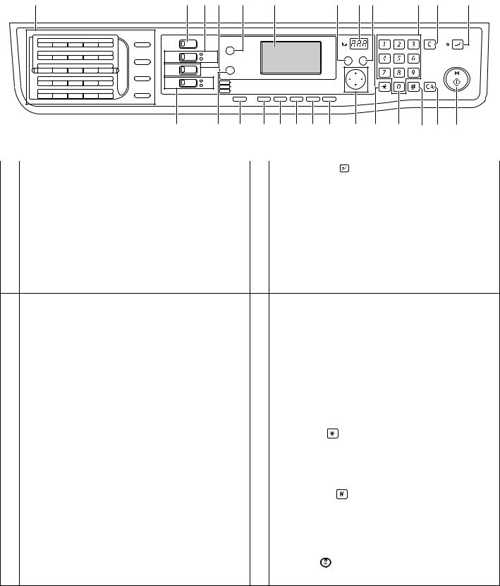
3. Operation Section
1 |
2 |
3 |
4 |
6 |
8 |
10 |
9 11 |
12 13 |
14 |
01 |
02 |
03 |
04 |
05 |
SPEAKER |
|
|
|
|
|
|
|
|
|
|
ABC |
DEF |
INTERRUPT |
COPY |
|
FAX STATUS |
|
|
|
|
|
|
|
|
|
|||||||
|
|
|
|
|
|
|
|
|
|
|
|
|
|
|
|
|||
|
|
|
|
|
SHIFT |
|
|
|
|
|
|
|
|
|
GHI |
JKL |
MNO |
|
06 |
07 |
08 |
09 |
10 |
|
|
ON LINE |
|
|
|
|
|
|
BACK |
|
|||
REDIAL/PAUSE |
|
|
|
|
|
|
OK |
|
|
|
||||||||
|
|
|
|
|
DATA |
SPECIAL |
|
|
|
|
|
|
|
|
|
|||
|
|
|
|
|
|
|
|
|
|
|
|
|
|
|
|
|||
11 |
12 |
13 |
14 |
15 |
|
|
|
FUNCTION |
|
|
|
|
|
PQRS |
TUV |
WXYZ |
|
|
|
SCAN |
|
|
|
|
|
|
|
|
|
||||||||
|
|
|
|
|
SPEED |
|
|
|
|
|
|
|
|
|
|
|
|
|
|
|
|
|
|
|
|
|
|
|
|
|
|
|
|
|
|
|
|
16 |
17 |
18 |
19 |
20 |
SYMBOL |
FAX |
LINE |
COPY |
EXPOSURE |
PAPER |
ZOOM |
AUTO% |
OUTPUT |
DUPLEX |
|
|
@.-_ |
|
|
|
|
|
|
|
|
|
|
||||||||||
|
|
|
|
|
DATA |
|
|
|
|
|||||||||
|
|
|
|
|
|
|
SCAN |
COLOR MODE |
RESOLUTION |
ADDRESS |
FORMAT |
ORIGINAL SIZE |
DUPLEX SCAN |
|
|
|
|
|
|
|
|
|
|
|
|
|
|
|
|
|
|||||||
21 |
22 |
23 |
24 |
25 |
COMM. SETTING |
|
|
FAX |
PROGRAM |
RESOLUTION |
ADDRESS |
BROADCAST |
ORIGINAL SIZE |
DUPLEX SCAN |
ACC. #-C |
|
READ-END |
|
|
|
|
|
|
|
|
|
|
|
|
|
|
|
|
|
|
||
|
|
|
|
|
SPACE/– |
|
|
|
|
|
|
|
|
|
|
|
|
|
|
5 |
7 |
15 |
16 17 18 19 20 |
21 |
22 |
23 |
24 25 |
26 |
|
|
|
|
|
|
|
|
|
|||
1 |
Keys for fax function (when the fax option is installed) |
|
|
14 |
[INTERRUPT] key ( |
) / INTERRUPT indicator |
|
|||
|
These are used in fax mode. |
|
|
|
Interrupts a copy run to allow an interrupt copy job to be performed. |
|||||
|
|
|
|
|
|
|
|
|
|
|
2 |
[COPY] key / indicator |
|
|
15 |
[EXPOSURE] key |
|
|
|
|
|
|
Press to select copy mode. |
|
|
|
Use to select the exposure mode. "AUTO", "TEXT", or "PHOTO" can |
|||||
|
If pressed when "Ready to copy." appears or during warm-up, the |
|
be selected. |
|
|
|
|
|
||
|
total number of sheets used appears while the key is pressed. |
|
|
|
|
|
|
|
|
|
|
|
|
|
|
|
|
|
|
|
|
3 |
[PRINT] key / indicator |
|
|
16 |
[PAPER] key |
|
|
|
|
|
|
Press to select print mode. |
|
|
|
Use to manually select a paper tray. |
|
|
|
||
nONLINE indicator
Print jobs can be received when this indicator is lit.
nDATA indicator
This lights steadily when there is a print job in memory that has not been printed, and blinks during printing.
4 |
[SCAN] key / indicator |
17 |
[ZOOM] key |
|
|
|
Press to select scan mode. (To connect a computer to the USB port |
|
Press to select a reduction or enlargement copy ratio. |
||
|
on the machine and use the scanner function. To use the machine |
|
|
|
|
|
as a network scanner.) |
|
|
|
|
|
|
|
|
|
|
5 |
[FAX] key / indicator (when the fax option is installed) |
18 |
[AUTO%] key |
|
|
|
LINE indicator, DATA indicator This key is used in fax mode. |
|
Press to have the copy ratio selected automatically. |
||
|
|
|
|
|
|
6 |
[FAX STATUS] key (when the fax option is installed) |
19 |
[OUTPUT] key |
|
|
|
This key is used in fax mode. |
|
Use to select the sort function. |
||
|
|
|
|
||
7 |
[SPECIAL FUNCTION] key |
20 |
[DUPLEX] key (only on models that support two-sided printing) |
||
|
Press to select special functions. |
|
Select the two-sided copying mode. |
||
|
|
|
|
|
|
8 |
Display |
21 |
Arrow keys |
|
|
|
Shows various messages. |
|
Press to move the highlighting (which indicates that an item is |
||
|
|
|
selected) in the display. |
|
|
|
|
|
|
|
|
9 |
Copy number display |
22 |
[ACC.#-C] key ( |
) |
|
|
The selected number of copies appears. During copying, this shows |
|
Press the end the use of an account and return the display to the |
||
|
the remaining number of copies. |
|
account number entry screen. |
||
|
|
|
|
|
|
10 |
[BACK] key |
23 |
[0] key |
|
|
|
Press to return the display to the previous screen. |
|
Press during a continuous copy run to display the number of copies |
||
|
|
|
completed. |
|
|
|
|
|
|
|
|
11 |
[OK] key |
24 |
[READ-END] key ( |
) |
|
|
Press to enter the selected setting. |
|
When copying in sort mode from the document glass, press this key |
||
|
|
|
when you have finished scanning the original pages and are ready to |
||
|
|
|
start copying. |
|
|
|
|
|
|
|
|
12 |
Numeric keys |
25 |
[CA] key |
|
|
|
Use to select the number of copies. |
|
Clears all selected settings and returns the machine to the default |
||
|
|
|
settings. |
|
|
|
|
|
|
|
|
13 |
[C] key |
26 |
[START] key ( |
) / indicator |
|
|
Press to clear the set number of copies or stop a copy run. |
|
Copying is possible when this indicator is on. Press the key to start |
||
|
|
|
copying. |
|
|
MX-M200D EXTERNAL VIEWS AND INTERNAL STRUCTURES 5-3
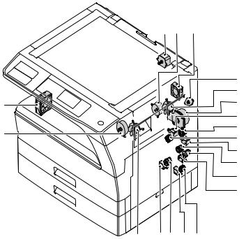
4. Motor, solenoid, clutch
1 2 18
|
3 |
|
|
4 |
|
17 |
5 |
|
|
||
|
6 |
|
19 |
7 |
|
8 |
||
|
||
|
9 |
|
|
10 |
|
|
11 |
|
|
12 |
|
|
|
4 |
16 15 |
14 13 |
|
|
|
|
|
|
No. |
Name |
Code |
|
|
Function operation |
|
|
|
|
||
1 |
Mirror motor |
MRM |
Drives the optical mirror base (scanner unit). |
||
|
|
|
|
|
|
2 |
Toner motor |
TM |
Toner supply |
|
|
|
|
|
|
||
3 |
Duplex motor |
DPX |
Switchback operation and paper exit motor in duplex. (Only for MX-M160D/MX-M200D) |
||
|
|
|
|
||
4 |
Cooling fan motor |
CFM |
Cools the inside of the machine. |
||
|
|
|
|
|
|
5 |
Main motor |
MM |
Drives the machine. |
|
|
|
|
|
|
|
|
6 |
1st tray paper feed clutch |
CPFC1 |
Drive the pick up roller |
|
|
|
|
|
|
|
|
7 |
PS clutch |
RRC |
Drives the resist roller |
|
|
|
|
|
|
||
8 |
Paper feed solenoid |
CPSOL1 |
Solenoid for paper feed from tray |
||
|
|
|
|
||
9 |
Resist roller solenoid |
RRS |
Resist roller rotation control solenoid |
||
|
|
|
|
||
10 |
Bypass tray paper transport clutch |
MPTC |
Drives the bypass tray paper transport roller. |
||
|
|
|
|
||
11 |
Bypass tray paper feed clutch |
MPFC |
Drives the bypass tray paper feed roller. |
||
|
|
|
|
||
12 |
Bypass tray paper feed solenoid |
MPFS |
Bypass tray paper feed solenoid |
||
|
|
|
|
||
13 |
2nd tray transport clutch |
CPFC2 |
Drives the 2nd tray transport roller. |
||
|
|
|
|
|
|
14 |
2nd tray transport solenoid |
FSOL1 |
2nd tray transport solenoid |
|
|
|
|
|
|
||
15 |
2nd tray paper feed clutch |
CPFC1 |
Drives the 2nd tray paper feed roller. |
||
|
|
|
|
|
|
16 |
2nd tray paper feed solenoid |
PSOL2 |
2nd tray transport solenoid |
|
|
|
|
|
|
||
17 |
Exhaust fan motor |
VFM |
Cools the inside of the machine. |
||
|
|
|
|
||
18 |
Cooling fan motor |
CFM |
Cools the inside of the machine. |
||
|
|
|
|
|
|
19 |
Job separator motor |
|
Job separator tray up/down |
|
|
|
|
|
|
|
|
MX-M200D EXTERNAL VIEWS AND INTERNAL STRUCTURES 5-4
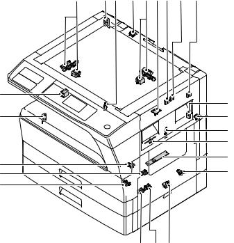
5. Sensor, switch
23 |
1 |
2 |
22 |
24 3 18 |
19 |
20 |
|
(AB) |
|
|
(INCH) |
(AB) |
|
|
|
|
|
(INCH) |
16 |
|
21 |
|
|
|
15 |
|
4 |
|
|
5 |
|
|
6 |
14 |
7 |
|
8 |
||
13 |
||
|
||
12 |
|
|
|
|
11 |
10 |
9 |
|
|
|
|
|
|
No. |
Name |
Code |
|
|
Function operation |
|
|
|
|
||
1 |
Mirror home position sensor |
MHPS |
Detects the mirror (scanner unit) home position. |
||
|
|
|
|
|
|
2 |
Side door switch |
DSWR |
Side door open detection |
|
|
|
|
|
|
|
|
3 |
Paper exit sensor (paper exit side) |
POD1 |
Detects paper exit. |
|
|
|
|
|
|
|
|
4 |
Paper exit sensor (DUP side) |
PDPX |
Paper transport detection |
|
|
|
|
|
|
||
5 |
Thermistor |
RTH |
Fusing section temperature detection |
||
|
|
|
|
||
6 |
Thermostat |
RDTCT |
Fusing section abnormally high temperature detection |
||
|
|
|
|
||
7 |
Toner density sensor |
TCS |
Detects the toner density in the developing unit. |
||
|
|
|
|
|
|
8 |
2nd tray detection switch |
CSD2 |
2nd tray detection |
|
|
|
|
|
|
||
9 |
Bypass tray sensor |
MPED |
Bypass tray transport detection |
||
|
|
|
|
||
10 |
2nd tray door open/close sensor |
DRS2 |
2nd tray door open/close detection |
||
|
|
|
|
||
11 |
2nd tray door paper pass sensor |
PPD2 |
2nd tray paper entry detection |
||
|
|
|
|
||
12 |
2nd tray paper empty sensor |
CSS2 |
2nd tray paper empty detection |
||
|
|
|
|
|
|
13 |
Paper in sensor |
PIN |
Paper transport detection |
|
|
|
|
|
|
|
|
14 |
Tray empty |
CSS1 |
Tray paper entry detection |
|
|
|
|
|
|
||
15 |
Front cover SW |
DSWF |
Front cover open detection |
||
|
|
|
|
||
16 |
Power switch |
MAIN SW |
Turns ON/OFF the main power source. |
||
|
|
|
|
|
|
18 |
Tray full sensor |
TRAY-D |
Tray full detection |
|
|
|
|
|
|
||
19 |
Job separator paper presence/empty |
TRAY-FULL |
Job separator tray paper presence/empty detection |
||
|
sensor |
|
|
|
|
|
|
|
|
||
20 |
Job separator HP sensor |
LFT UP |
Job separator HP detection |
||
|
|
|
|
||
21 |
Lower limit switch |
/ JOBS_DLD |
Job separator tray lower limit position detection |
||
|
|
|
|
||
22 |
OC sensor |
OCSW |
Original cover and SPF open/close detection |
||
|
|
|
|
|
|
23 |
Original size sensor(Main Scaning) |
DSIN0 |
Original size detection |
|
|
|
|
|
|
|
|
24 |
Original size sensor(Sub Scaning) |
DSIN1 |
Original size detection |
|
|
|
|
|
|
|
|
MX-M200D EXTERNAL VIEWS AND INTERNAL STRUCTURES 5-5
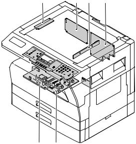
6. PWB unit
1 |
10 |
2 |
3 |
7 


9 


 4
4
|
6 |
5 |
|
|
|
No. |
Name |
Function operation |
|
|
|
1 |
Copy lamp Inverter PWB |
Copy lamp control |
|
|
|
2 |
CCD sensor PWB |
Image scanning |
|
|
|
3 |
Main control PWB |
Main control PWB |
|
|
|
4 |
2nd tray PWB |
2nd tray control |
|
|
|
5 |
High voltage PWB |
High voltage control |
|
|
|
6 |
Power PWB |
AC power input/DC power control |
|
|
|
7 |
Operation main PWB |
Operation panel input/Display, operation panel section control |
|
|
|
9 |
LCD OPE PWB |
Display and operation panel control |
|
|
|
10 |
IMC2 PWB |
Electronic sort, USB2.0 |
|
|
|
MX-M200D EXTERNAL VIEWS AND INTERNAL STRUCTURES 5-6
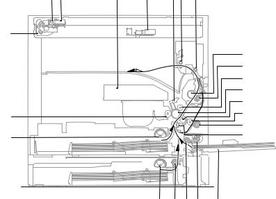
7. Cross sectional view
1 |
2 |
3 |
4 |
5 6 |
7 |
18 |
|
|
8 |
|
9 |
|
10 |
|
11 |
|
12 |
23 |
13 |
|
|
14 |
22 |
15 |
|
|
21 |
20 19 17 |
16 |
|
|
|
|
|
No. |
Name |
|
|
Function/Operation |
|
|
|
|
|
1 |
Copy lamp |
Image radiation lamp |
|
|
|
|
|
||
2 |
Copy lamp unit |
Operates in synchronization with No. 2/3 mirror unit to radiate documents |
||
|
|
sequentially. |
|
|
|
|
|
||
3 |
LSU unit |
Converts image signals into laser beams to write on the drum. |
||
|
|
|
||
4 |
Lens unit |
Reads images with the lens and the CCD. |
||
|
|
|
||
5 |
MC holder unit |
Supplies negative charges evenly on the drum. |
||
|
|
|
|
|
6 |
Paper exit roller |
Used to discharge paper. |
|
|
|
|
|
|
|
7 |
Transport roller |
Used to transport paper. |
|
|
|
|
|
||
8 |
Upper heat roller |
Fuses toner on paper (with the teflon roller). |
||
|
|
|
||
9 |
Lower heat roller |
Fuses toner on paper (with the silicon rubber roller). |
||
|
|
|
||
10 |
Waste toner transport roller |
Transports waste toner to the waste toner box. |
||
|
|
|
|
|
11 |
Drum unit |
Forms images. |
|
|
|
|
|
||
12 |
Transfer charger unit |
Transfer images (on the drum) onto paper. |
||
|
|
|
|
|
13 |
DUP follower roller |
Transports paper for duplex. |
|
|
|
|
|
|
|
14 |
Duplex transport roller |
Transports paper for duplex . |
|
|
|
|
|
||
15 |
Resist roller |
Takes synchronization between the paper lead edge and the image lead edge. |
||
|
|
|
|
|
16 |
Bypass tray |
Bypass tray |
|
|
|
|
|
|
|
17 |
Bypass tray paper pick up roller |
Picks up paper in bypass tray. |
|
|
|
|
|
||
18 |
No. 2/3 mirror unit |
Reflects the images from the copy lamp unit to the lens unit. |
||
|
|
|
||
19 |
Bypass tray transport roller |
Transports paper from the bypass tray. |
||
|
|
|
||
20 |
2nd tray paper transport roller |
Transports paper from the 2nd tray. (MX-M200D only) |
||
|
|
|
||
21 |
2nd tray paper pick up roller |
Picks up paper from the 2nd tray. (MX-M200D only) |
||
|
|
|
|
|
22 |
1st tray paper feed roller |
Picks up paper from the 1st tray. |
|
|
|
|
|
|
|
23 |
MG roller |
Puts toner on the OPC drum. |
|
|
|
|
|
|
|
MX-M200D EXTERNAL VIEWS AND INTERNAL STRUCTURES 5-7
[6]ADJUSTMENTS
1.Adjustment item list
|
Section |
|
Adjustment item |
Adjustment procedure/SIM No. |
|
|
|
|
|
A |
Process |
(1) |
Developing doctor gap adjustment |
Developing doctor gap adjustment |
|
section |
|
|
|
|
(2) |
MG roller main pole position adjustment |
MG roller main pole position adjustment |
|
|
|
|
|
|
|
|
(3) |
Developing bias voltage check |
|
|
|
|
|
|
|
|
(4) |
Main charger voltage check |
|
|
|
|
|
|
B |
Mechanism |
(1) |
Image position adjustment |
SIM-50 |
|
section |
|
|
|
|
(2) |
Main scanning direction (FR direction) distortion balance |
No. 2/3 mirror base unit installing position adjustment |
|
|
|
|
adjustment |
|
|
|
|
Copy lamp unit installing position adjustment |
|
|
|
|
|
|
|
|
(3) |
Main scanning direction (FR direction) distortion adjustment |
Rail height adjustment |
|
|
|
|
|
|
|
(4) |
Sub scanning direction (scanning direction) distortion |
Winding pulley position adjustment |
|
|
|
adjustment |
|
|
|
|
|
|
|
|
(5) |
Main scanning direction (FR direction) magnification ratio |
SIM 48-1 |
|
|
|
adjustment |
|
|
|
|
|
|
|
|
(6) |
Sub scanning direction (scanning direction) magnification ratio |
OC mode in copying (SIM 48-1) |
|
|
|
adjustment |
|
|
|
|
SPF mode in copying (SIM 48-5) |
|
|
|
|
|
|
|
|
(7) |
Off center adjustment |
OC mode (SIM 50-12) |
|
|
|
|
|
|
|
|
|
SPF mode (SIM 50-12) |
|
|
|
|
|
|
|
(8) |
SPF white correction pixel position adjustment |
SIM63-7 |
|
|
|
(required in an SPF model when replacing the lens unit) |
|
|
|
|
|
|
C |
Image density |
(1) |
Copy mode |
SIM 46-1 |
|
adjustment |
|
|
|
|
|
|
|
|
2.Copier adjustment
A.Process section
(1) Developing doctor gap adjustment
1)Loosen the developing doctor fixing screw A.
2)Insert a thickness gauge of 1.5mm to the three positions at 20mm and 150mm from the both ends of the developing doctor as shown.
20mm
150mm
20mm
A
1


 A DV front cover


3
A
2
3)Push the developing doctor in the arrow direction, and tighten the fixing screws of the developing doctor in the sequence of 13233.
4)Check the clearance of the developing doctor. If it is within the specified range, then fix the doctor fixing screw with screw lock.
*When inserting a thickness gauge, be careful not to scratch the developing doctor and the MG roller.
<Adjustment specification>
Developing doctor gap
Both ends (20mm from the both ends) : 1.5 0.1mm
0.1mm
C (Center) (150mm from the both ends) : 1.5 0.1mm
0.1mm
(2) MG roller main pole position adjustment
1)Remove the DV front cover, and put the developing tank on a flat surface.
2)Tie a string to a needle or a pin.
3)Hold the string and bring the needle close to the MG roller horizontally. (Do not use paper clip, which is too heavy to make a correct adjustment.) (Put the developing unit horizontally for this adjustment.)
4)Do not bring the needle into contact with the MG roller, but bring it to a position 2 or 3mm apart from the MG roller. Mark the point on the MG roller which is on the extension line from the needle tip.
5)Measure the distance from the marking position to the top of the doctor plate of the developing unit to insure that it is 18mm.
If the distance is not within the specified range, loosen the fixing screw A of the main pole adjustment plate, and move the adjustment plate in the arrow direction to adjust.
MX-M200D ADJUSTMENT 6-1
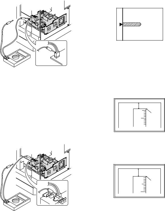
(3)Developing bias voltage check
Note:Use a digital multi-meter with an internal resistance of 10MΩ or more.
1)Set the digital multi-meter range above 500 Vdc.
2)Put the test rod of the digital multi-meter on the developing bias voltage output check pin.
3)Turn on the power, execute SIM25-1.
<Specification>
Mode |
Specification |
|
|
Developing bias voltage |
DC - 400±10V |
|
|
(4) Grid bias voltage check
Note:Use a digital multi-meter with an internal resistance of 10MΩ or more.
1)Set the digital multi-meter range above 600 Vdc.
2)Put the test rod of the digital multi-meter on the grid bias voltage output check pin.
3)Turn on the power.
(The voltage is outputted in the grid bias High output mode during warming up, and in the grid bias Low output mode when warming up is completed.)
<Specification>
Mode |
Specification |
|
|
Grid bias LOW |
DC - 380±8V |
|
|
Grid bias HIGH |
DC - 525±10V |
|
|
B.Mechanism section
Note: If a jam error or paper empty occurs during copying in the adjustment by the simulation, the image data is not saved, and therefore recopying is required.
(1) Image position adjustment
a.OC image lead edge position adjustment (SIM 50-1)
Note:In advance to this adjustment, the sub scanning magnification ratio adjustment must be performed.
1) Set a scale on the OC table as shown below.
2)Make a copy.
3)Check the copy output. If necessary, perform the following adjustment procedures.
4)Execute SIM 50-1.
5)Set the OC lead edge position set value (PHOTO indicator ON) to [1] The OC image scanning start position is shifted inside the document edge.
6)Set the 1st tray lead edge void adjustment value (TEXT indicator ON) * to [1]
The lead edge void becomes the minimum.
7)Set the 1st tray print start position value (AUTO, 1st tray indicator ON) to [1] and make a copy.
The print start position is shifted inside the document edge.
5mm |
5 |
4mm |
10 |
*The dimension varies depending on the model.
8)Measure the image loss R of the copied image. Enter the set value of the image scanning lead edge position (PHOTO indicator ON) again.
•1 step of the set value corresponds to about 0.1mm shift. •Calculate the set value from the formula below. R/0.1(mm) = Image loss set value
<R: Image loss measurement value (mm)>
5mm |
0mm |
5 |
10 |
*The scanning edge is set.
(A line may be printed by scanning the document edge.)
Example: 4/0.1 = 40 = about 40
Note:If the set value is not obtained from the above formula, perform the fine adjustment.
MX-M200D ADJUSTMENT 6-2

9) Measure the distance H between the paper lead edge and the image print start position. Set the image print start position set value (AUTO, 1st tray indicator ON) again.
•1 step of the set value corresponds to about 0.1mm shift. •Calculate the set value from the formula below. H/0.1(mm) = Image print start position set value
<H: Print start position measurement value (mm)>
0mm |
0mm |
5 |
10 |
*Fit the print edge with the paper edge, and perform the lead edge adjustment.
Example: 5/0.1 = 50 = about 50
Note:If the set value is not obtained from the above formula, perform the fine adjustment.
10) Set the lead edge void adjustment value (TEXT indicator ON)* again. •1 step of the set value corresponds to about 0.1mm shift.
•Calculate the set value from the formula below. B/0.05 (mm) = Lead edge void adjustment value <B: Lead edge void (mm)>
2.5mm |
5 |
2.5mm |
10 |
Example: |
When setting the lead edge void to 2.5mm |
|
:2.5 /0.05 = about 50 |
Note:If the set value is not obtained from the above formula, perform the fine adjustment.
*2nd tray lead edge void adjustment: Exposure display <<AUTO + TEXT + PHOTO>>
Bypass tray lead edge void adjustment: (TEXT indicator and PHOTO indicator ON)
<Duplex mode adjustment>
OC 2nd print surface (Auto duplex) lead edge position adjustment: SIM50-19 <<PHOTO>>
*For the adjustment procedure, set to S → D mode before execution.
Note:Before performing the 2nd print surface lead edge position adjustment and the lead edge void adjustment, be sure to perform the 1st print surface lead edge position adjustment in advance, and be sure to perform the 2nd print surface lead edge position adjustment and then the lead edge void adjustment in this sequence.
<Adjustment specification>
Adjustment |
SIM |
LED |
Set |
Spec |
Set |
mode |
|
|
value |
value |
range |
|
|
|
|
|
|
OC image lead |
SIM |
PHOTO |
R/0.1 |
Lead edge |
1 ~ 99 |
edge position |
50-1 |
|
|
|
|
|
|
|
|
void: |
|
1st tray print |
|
AUTO |
B/0.1 |
|
|
start position |
|
+ |
|
1 - 4mm |
|
|
|
1st tray |
|
Image loss: |
|
|
|
|
|
|
|
2nd tray print |
|
AUTO |
|
|
|
|
|
3mm or |
|
||
start position |
|
+ |
|
|
|
|
|
less |
|
||
|
|
2nd tray |
|
|
|
|
|
|
|
|
|
|
|
|
|
|
|
Bypass tray |
|
AUTO |
|
|
|
print start |
|
+ |
|
|
|
position |
|
Bypass |
|
|
|
|
|
tray |
|
|
|
|
|
|
|
|
|
Lead edge void |
|
TEXT |
B/0.05 |
|
|
|
|
|
|
|
|
OC 2nd print |
SIM |
PHOTO |
1 step: |
|
|
surface lead |
50-19* |
|
0.1mm shift |
|
|
edge position |
|
|
|
|
|
adjustment |
|
|
|
|
|
|
|
|
|
|
|
*(Set to S → D mode for before execution)
b.SPF image lead edge position adjustment (SIM50-6)
1) Set a scale on the OC table as shown below.
Note:Since the printed copy is used as a test chart, put the scale in paralled with the edge lines.
2)Make a copy, Then use the copy output as an original to make an SPF copy again.
3)Check the copy output. If necessary, perform the following adjustment procedures.
4)Execute SIM 50-6.
5)Set the SPF lead edge position set value (AUTO indicator ON) so that the same image is obtained as that obtained in the previous OC image lead edge position adjustment.
<Adjustment specification>
Adjustment mode |
SIM |
LED |
Set value |
Spec value |
Set |
|
|
|
|
|
range |
|
|
|
|
|
|
SPF image lead |
SIM |
AUTO |
1 step: |
Lead edge |
1 ~ 99 |
edge position |
50-6 |
|
0.1mm shift |
void: |
|
(1st print surface) |
|
|
|
1 - 4mm |
|
|
|
|
|
|
|
(2nd print surface) |
|
TEXT |
|
Image loss: |
|
|
|
|
|
|
|
|
|
|
|
3mm or |
|
|
|
|
|
less |
|
|
|
|
|
|
|
MX-M200D ADJUSTMENT 6-3

c.Rear edge void adjustment (SIM50-1, SIM50-19)
1) Set a scale as shown in the figure below.
A4(8.5" x 11")
Paper rear edge
2)Set the document size to A4 (8.5" x 11"), and make a copy at 100%.
3)If necessary, perform the following adjustment procedure.
Void amount (Standard value: 4mm or less)
Scale image
Paper rear edge
4)Execute SIM 50-1 and set the density mode to AUTO + TEXT + PHOTO (Rear edge void).The currently set adjustment value is displayed.
5)Enter the set value and press the [START] key. The correction value is stored and a copy is made.
<Duplex mode adjustment>
*1st print surface (auto duplex) rear edge void adjustment: SIM50-19 <<AUTO>>
*2nd print surface (auto duplex) rear edge void adjustment: SIM50-19<<TEXT>>
*Set to S → D mode before execution.
Note:Before performing the 2nd print surface rear edge void adjustment, be sure to perform the 2nd print surface lead edge position adjustment. Never reverse the sequence.
<Adjustment specification>
Mode |
SIM |
LED |
Set value |
Specifi- |
Set |
|
|
|
|
cation |
range |
|
|
|
|
|
|
Rear edge void |
SIM |
AUTO |
1 step: |
4mm or |
1 ~ 99 |
|
50-1 |
+ |
0.1mm shift |
less |
|
|
|
TEXT |
|
|
|
|
|
+ |
|
|
|
|
|
PHOTO |
|
|
|
|
|
|
|
|
|
1st print |
SIM |
AUTO |
|
|
|
surface rear |
50-19* |
|
|
|
|
edge void |
|
|
|
|
|
|
|
|
|
|
|
2nd print |
SIM |
TEXT |
|
|
|
surface rear |
50-19* |
|
|
|
|
edge void |
|
|
|
|
|
|
|
|
|
|
|
*Set to S → D mode before execution
d. Paper off center adjustment (SIM50-10)
1)Set a test chart (UKOG-0089CSZZ) on the document table.
2)Select a paper feed port and make a copy. Compare the copy and the test chart. If necessary, perform the following adjustment procedure.
3)Execute SIM 50-10. After completion of warm-up, shading is performed and the currently set off center adjustment value of each paper feed port is displayed.
4)Enter the set value and press the [START] key. The correction value is stored and a copy is made.
<Duplex mode adjustment>
*2nd print surface (auto duplex) off-center adjustment: SIM50-10 (TEXT, 1st tray indicator)
<Adjustment specification>
Mode |
SIM |
LED |
Set value |
Specifi- |
Set |
|
|
|
|
cation |
range |
|
|
|
|
|
|
Paper off |
SIM |
AUTO |
Add 1: |
Single: |
1 ~ 99 |
center |
50-10 |
+ |
0.1mm shift |
Center |
|
|
|
Selected |
to R side. |
±2.0mm |
|
|
|
tray ON |
|
|
|
|
|
|
Reduce 1: |
|
|
2nd print |
SIM |
TEXT |
Duplex: |
|
|
surface off- |
50-10 |
+ |
0.1mm shift |
Center |
|
center |
|
1st tray |
to L side. |
±2.5mm |
|
|
|
|
|
|
|
e.Side edge void area adjustment (SIM26-43)
Note:Before performing this adjustment, be sure to check that the paper off center adjustment (SIM 50-10) is completed.
1)Set a test chart (UKOG-0089CSZZ) on the document table.
2)Select a paper feed port and make two copies. Compare the 2nd copy and the test chart. If necessary, perform the following
adjustment procedure.
*The 1st copy does not show the void. Be sure to check the 2nd copy.
3)Execute SIM 26-43 and set the density mode to AUTO(right edge void) + TEXT (Left edge void).
The currently set adjustment value is displayed.
4)Enter the set value and press the [START] key. The correction value is stored.
<Adjustment specification>
ode |
SIM |
LED |
Set value |
Specifi- |
Set |
|
|
|
|
cation |
range |
|
|
|
|
|
|
Left edge void |
SIM |
AUTO |
1 step: |
0 ~ 10mm |
0 ~ 10 |
|
26-43 |
(right |
0.5mm shift |
|
|
|
|
edge) |
|
|
|
|
|
+ |
|
|
|
|
|
TEXT |
|
|
|
|
|
(left edge) |
|
|
|
|
|
|
|
|
|
*The void adjustment values on the right and the left must be the same.
(2)Main scanning direction(FR direction) distortion balance adjustment
1) Remove the OC glass and the right cabinet.
|
(1) |
(2) |
(3) |
(1) |
|
|
(4) |
|
(3) |
MX-M200D ADJUSTMENT 6-4

2) Loosen the copy lamp unit wire fixing screw.
4)Loosen the set screw of the scanner drive pulley which is not in contact with No. 2/3 mirror base unit positioning plate.
5)Without moving the scanner drive pulley shaft, manually turn the scanner drive pulley until the positioning plate is brought into contact with No. 2/3 mirror base unit, then fix the scanner drive pulley.
Wire fixing screw
3)Manually turn the mirror base drive pulley and bring No. 2/3 mirror base unit into contact with the positioning plate. At that time, if the front frame side and the rear frame side of No. 2/3 mirror base unit are brought into contact with the positioning plate at the same time, the mirror base unit parallelism is proper. If one of them is in contact with the positioning plate, perform the adjustment of 4).
6)Put No. 2/3 mirror base unit on the positioning plate again, push the projections on the front frame side and the rear frame side of the copy lamp unit to the corner frame, and tighten the wire fixing screw.
MX-M200D ADJUSTMENT 6-5
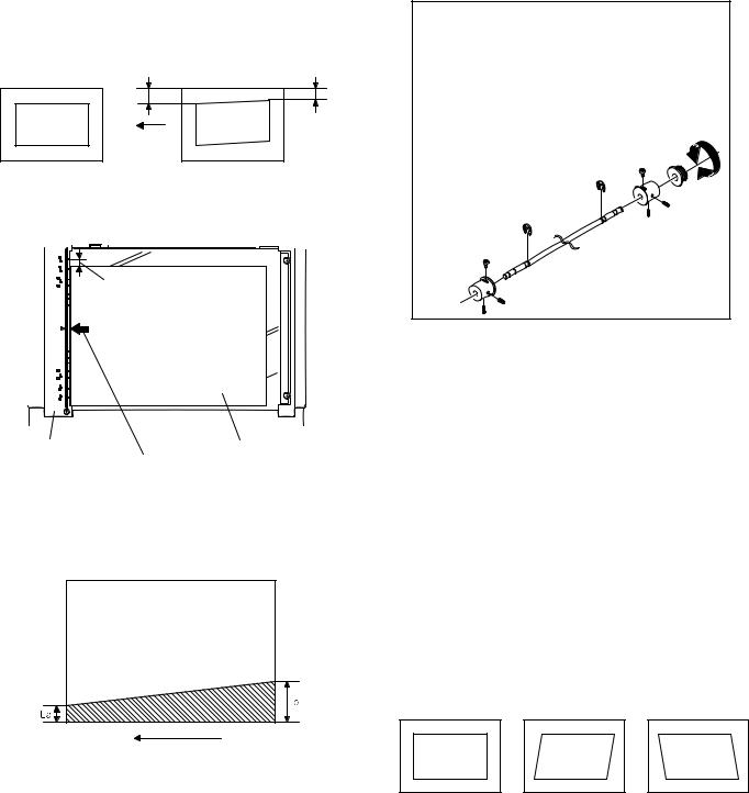
(3)Main scanning direction (FR direction) distortion adjustment
This adjustment must be performed in the following cases: •When the mirror base drive wire is replaced.
•When the lamp unit, or No. 2/3 mirror holder is replaced. •When a copy as shown is made.
La |
Lb |
Paper exit direction
Original |
Copy |
1) Set A3 (11" x 17") white paper on the original table as shown below.
Allow a little space.
Glass holding plate |
A3 (11" x 17") white paper |
|
Fit the paper edge and
the glass holding plate edge.
2)Open the original cover and make a normal (100%) copy.
3)Measure the width of the black background at the lead edge and at the rear edge.
Paper exit direction
La: Lead edge black background width
Lb: Rear edge black background width
If the width (La) of the black background at the lead edge is equal that (Lb) at the rear edge, there is no need to execute the following procedures of 4) ~ 7).
4)Loosen the mirror base drive pulley fixing screw on the front frame side or on the rear frame side.
 When La < Lb
Turn the mirror base drive pulley on the front frame side in the arrow direction A.
(Do not move the mirror base drive pulley shaft.)
 When La > Lb
Turn the mirror base drive pulley on the front frame side in the arrow direction A.
(Do not move the mirror base drive pulley shaft.)
Rear side
A
B
Front side
5)Tighten the mirror base drive pulley fixing screw.
<Adjustment specification>
La = Lb
6)Execute the main scanning direction (FR) distartion balance adjustment previously described in 2) again.
(4)Sub scanning direction (scanning direction) distortion adjustment
When there is no skew copy in the mirror base scanning direction and there is no horizontal error (right angle to the scanning direction), the adjustment can be made by adjusting the No. 2/3 mirror base unit rail height.
Before performing this adjustment, be sure to perform the horizontal image distortion adjustment in the laser scanner section.
This adjustment must be performed in the following cases: •When the mirror base wire is replaced.
•When the copy lamp unit or No. 2/3 mirror unit is replaced. •When the mirror unit rail is replaced or moved.
•When a following copy is made.
Original |
Copy A |
Copy B |
MX-M200D ADJUSTMENT 6-6
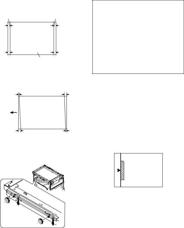
1)Making of a test sheet
Make test sheet by drawing parallel lines at 10mm from the both ends of A3 (11" x 17") white paper as shown below. (These lines must be correctly parallel to each other.)
Parallel line |
Parallel line |
10mm |
10mm |
10mm |
10mm |
White paper
2)Make a normal (100%) copy of the test sheet on A3 (11" x 17") paper. (Fit the paper edge with the glass holding plate edge.)
3)Measure the distances (La, Lb, Lc, Ld) at the four corners as shown below.
La |
Lc |
Paper exit direction
Lb |
Ld |
When La = Lb and Lc = Ld, no need to perform the procedures 4) and 5).
4)Move the mirror base F rail position up and down (in the arrow direction) to adjust.
Note:Do not adjust the rail on the rear side.
If the rail on the rear side is adjusted, an error may occur. Only the rail on the front side can be adjusted.
 When La > Lb
Shift the mirror base B rail upward by the half of the difference of La - Lb.
 When La < Lb
Shift the mirror base B rail downward by the half of the difference of Lb - La.
Example: When La = 12mm and Lb = 9mm, shift the mirror base B rail upward by 1.5mm.
 When Lc > Ld
Shift the mirror base B rail downward by the half of the difference of Lc - Ld.
 When Lc < Ld
Shift the mirror base B rail downward by the half of the difference of Ld - Lc.
 When moving the mirror base rail, hold the mirror base rail with your hand.
<Adjustment specification>
La = Lb, Lc = Ld
5)After completion of adjustment, manually turn the mirror base drive pulley, scan the mirror base A and mirror base B fully, and check that
the mirror bases are not in contact with each other.
*If the mirror base rail is adjusted to extreme, the mirror base may contact the frame or original glass. Be careful to avoid this.
(5)Main scanning direction (FR direction) magnification ratio adjustment (SIM 48-1)
Note:Before performing this adjustment, be sure the CCD unit is within specification.
1) Put a scale on the original table as shown below.
2)Execute SIM 48-1.
3)After warm-up, shading is performed and the current set value of the main scanning direction magnification ratio is displayed on the display section in 2 digits.
4)Select the mode and press the [START] key again.
5)Manual correction mode (TEXT indicator ON) Enter the set value and press the [START] key. The set value is stored and a copy is made.
MX-M200D ADJUSTMENT 6-7
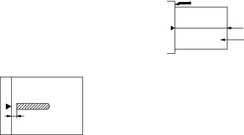
<Adjustment specification>
Note: A judgment must be made with 200mm width, and must not be made with 100mm width.
Mode |
Specification |
SIM |
Set value |
Set range |
|
|
|
|
|
Main scanning |
At normal: |
SIM 48-1 |
Add 1:0.1% |
1 ~ 99 |
direction |
±1.0% |
|
increase |
|
magnification |
|
|
Reduce 1: |
|
ratio |
|
|
0.1% |
|
|
|
|
decrease |
|
|
|
|
|
|
(6)Sub scanning direction (scanning direction) magnification ratio adjustment (SIM 48-1, SIM 48-5)
a. OC mode in copying (SIM48-1)
Note:Before performing this adjustment, be sure the CCD unit is within specification.
1)Put a scale on the original table as shown below, and make a normal (100%) copy.
2)Compare the scale image and the actual image. If necessary, perform the following adjustment procedures.
3)Execute SIM 48-1.<<PHOTO>>
4)After warm-up, shading is performed and the current set value of the main scanning direction magnification ratio is displayed on the display section in 2 digits.
5)When the photo indicator is lighted by pressing the AUTO/TEXT/ PHOTO key, the current magnification ratio correction value in the sub scanning direction is displayed in lower 2 digits of the display section.
6)Enter the set value and press the [START] key. The set value is stored and a copy is made.
<Adjustment specification>
Mode |
Specification |
SIM |
Set value |
Set range |
|
|
|
|
|
Sub scanning |
Normal |
SIM 48-1 |
Add 1:0.1% |
1 ~ 99 |
direction |
±1.0% |
(PHOTO) |
increase |
|
magnification |
|
|
Reduce 1: |
|
ratio |
|
|
0.1% |
|
(OC mode) |
|
|
decrease |
|
|
|
|
|
|
b. RSPF sub scanning direction magnification ratio (SIM48-5)
Note:
•Before performing this adjustment, be sure the CCD unit is within specification.
•Before performing this adjustment, the OC mode adjustment in copying must be completed.
1)Put a scale on the original table as shown below, and make a normal (100%) copy to make a test chart.
Note:Since the printed copy is used as a test chart, put the scale in parallel with the edge lines.
2)Set the test chart on the SPF and make a normal (100%) copy.
3)Compare the scale image and the actual image. If necessary, perform the following adjustment procedures.
4)Execute SIM 48-5.
5)After warm-up, shading is performed.
The AUTO indicator lights up and the current front surface sub scanning direction magnification ratio correction value is displayed in two digits on the display section.
6)Enter the set value and press the [START] key. The set value is stored and a copy is made.
7)Change the mode from the duplex original mode to the simplex original mode.
TEXT indicator lights up and the current back surface sub scanning direction magnification ratio is displayed in two digits on the display section.
8)Enter the set value and press the [START] key. The set value is stored and a copy is made.
<Adjustment specification>
Mode |
Specification |
SIM |
Set value |
Set range |
|
|
|
|
|
Sub scanning |
Normal |
SIM 48-5 |
Add 1:0.1% |
1 ~ 99 |
direction |
±1.0% |
|
increase |
|
magnification |
|
|
Reduce 1: |
|
ratio |
|
|
0.1% |
|
(SPF mode) |
|
|
decrease |
|
|
|
|
|
|
(7) Off center adjustment (SIM 50-12)
a. OC mode (SIM50-12)
1)Make a test chart as shown below and set it so that its center line is fit with the original guide center mark.
*To make a test chart, draw a line on A3 or 11" x 17" paper at the center in the paper transport direction.
Original guide
Center
Copy paper
(A3 or 17" x 11")
2)Make a normal copy from the bypass tray, and compare the copy and the test chart.
If necessary, perform the following adjustment procedures.
3)Execute SIM 50-12.
4)After warm-up, shading is performed and the current set value of the off center adjustment is displayed on the display section in 2 digits.
5)Enter the set value and press the [START] key. The set value is stored and a copy is made.
<Adjustment specification>
Mode |
Specification |
SIM |
Set value |
Set range |
|
|
|
|
|
Original off |
Single: |
SIM 50-12 |
Add 1: |
1 ~ 99 |
center mode |
Center ±2.0mm |
(AUTO |
0.1mm shift |
|
(OC mode) |
|
indicator |
to R side |
|
|
|
ON) |
Reduce 1: |
|
|
|
|
0.1mm shift |
|
|
|
|
to L side |
|
|
|
|
|
|
MX-M200D ADJUSTMENT 6-8
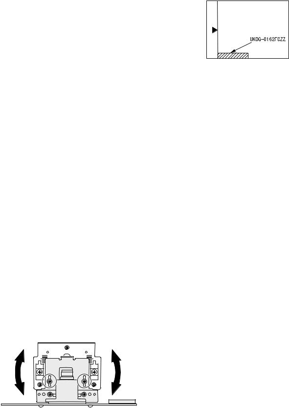
b. SPF original off-center adjustment (SIM50-12)
Note:Before performing this adjustment, be sure to check that the paper off center is properly adjusted.
1)Make a test chart for the center position adjustment and set it on the SPF.
<Adjustment specification>
Draw a line on a paper in the scanning direction.
2)Make a normal copy from the bypass tray, and compare the copy and the original test chart.
If necessary, perform the following adjustment procedures.
3)Execute SIM 50-12.
4)After warm-up, shading is performed and the current set value of the off center adjustment at each paper feed port is displayed on the display section in 2 digits.
5)Enter the set value and press the [START] key. The set value is stored and a copy is made.
<Adjustment specification>
Mode |
Specification |
SIM |
Set value |
Set |
|
|
|
|
range |
|
|
|
|
|
Original off |
Single: |
SIM |
Add 1: |
1 ~ 99 |
center |
Center ±3.0mm(TEXT |
50-12 |
0.1mm shift |
|
mode |
indicator) |
|
to R side |
|
(SPF mode) |
|
|
Reduce 1: |
|
Duplex: |
|
|
||
|
Center ±3.5mm(PHOTO |
|
0.1mm shift |
|
|
indicator) |
|
to L side |
|
|
|
|
|
|
(8) SPF white correction pixel position adjustment(SIM63-7) (required in an SPF model when replacing the lens unit)
1)Fully open the SPF.
2)Execute SIM 63-7.
If the value is 93 - 229, it is displayed on the display and written into the EEPROM.
If the value is 0 - 92 or 230 - 999, it is displayed on the display but not written into the EEPROM.
If the value is 1000 or above, “--” is displayed on the display and it is not written into the EEPROM.
•When the display is 0: Check that the SPF is open.
Check that the lamp is ON.(If the lamp is OFF,check the MCU connector.)
Check that the CCD harness is properly inserted into the MCU connector.
•When the display is 281 or above:
1)Remove the table glass.
2)Remove the dark box.
3)Slide the lens unit toward the front side and attach it,then execute
SIM.
•When the display is 143 or below:
1)Remove the table glass.
2)Remove the dark box.
3)Slide the lens unit toward the rear side and attach it,then execute SIM.
F R
C.Image density adjustment
(1)Copy mode (SIM 46-1)
1)Set a test chart (UKOG-0162FCZZ) on the OC table as shown below.
2)Put several sheets of A3 or 11" x 17" white paper on the test chart.
3)Execute SIM 46-1.
4)After warm-up, shading is performed and the current set value of the density level is displayed on the display section in 2 digits.
For mode selection, use the AUTO/TEXT/PHOTO key.
5)Change the set value with the numeric keys to adjust the copy image density.
6)Make a copy and check that the specification below is satisfied.
<Adjustment specification>
Density |
LED |
Exposure |
Sharp Gray |
Set value |
Set |
mode |
|
level |
Chart output |
|
range |
|
|
|
|
|
|
Auto |
Auto |
- |
"2" is slightly |
The greater the |
1 ~ 99 |
|
|
|
copied. |
set value is the |
|
|
|
|
|
greater the |
|
Text |
Text |
3 |
"3" is slightly |
|
|
|
|
|
copied. |
density is The |
|
|
|
|
|
smaller the set |
|
Photo |
Photo |
3 |
"2" is slightly |
|
|
(Error |
|
|
copied. |
value is the |
|
|
|
smaller the |
|
||
diffusion) |
|
|
|
|
|
|
|
|
density is. |
|
|
|
|
|
|
|
|
Toner |
Auto/ |
- |
"2" is slightly |
|
|
|
|
||||
save |
Photo |
|
copied |
|
|
|
|
|
|
|
|
Toner |
Text/ |
3 |
"3" is slightly |
|
|
save |
Photo |
|
copied |
|
|
|
|
|
|
|
|
Photo |
Auto/ |
3 |
"2" is slightly |
|
|
(Dither) |
Text/ |
|
copied |
|
|
|
Photo |
|
|
|
|
|
|
|
|
|
|
*When the lens unit is moved,execute the OC main scanning magnification ratio auto adjustment,SIM 48-1-1,SIM48-3 and the PF original off-center adjustment.
*This adjustment is basically O.K.with SIM 63-7.
MX-M200D ADJUSTMENT 6-9

[7] SIMULATIONS
1. Entering the simulation mode
Perform the following procedure to enter the simulation mode.
[#] key |
|
|
[ ] key |
|
[C] key |
|
[ ] key |
|
|
|||||
|
|
|
|
|
||||||||||
Main code |
|
[START] key |
|
|
Sub code |
|
|
[START] key |
||||||
|
|
|
||||||||||||
2. Canceling the simulation mode
When the clear all key is pressed, the simulation mode is cancelled. When the interruption key is pressed, the process is interrupted and the screen returns to the sub code entering display.
* After canceling the simulation mode, be sure to turn OFF/ON the power and check the operation.
Note: If the machine is terminated by a jam error or paper empty during copying in the adjustment by the simulation, recopying is required.
Note:The values in the simulation columns are not default values but sample values.
3. List of simulations
Main |
Sub |
Contents |
|
code |
code |
||
|
|||
|
|
|
|
01 |
01 |
Mirror scanning operation |
|
|
|
|
|
|
02 |
Mirror home position sensor (MHPS) status display |
|
|
|
|
|
02 |
01 |
Single paper feeder (SPF)/Reversing single pass |
|
|
|
feeder(RSPF) aging *2 |
|
|
|
|
|
|
02 |
SPF/RSPF sensor status display *2 |
|
|
|
|
|
|
03 |
SPF/RSPF motor operation check *2 |
|
|
|
|
|
|
08 |
SPF/RSPF paper feed solenoid operation check *2 |
|
|
|
|
|
|
09 |
RSPF reverse solenoid operation check *2 *3 |
|
|
|
|
|
|
11 |
SPF/RSPF PS release solenoid operation check *2 |
|
|
|
|
|
03 |
02 |
Shifter/job separator sensor status display |
|
|
|
|
|
|
03 |
Shifter operation check |
|
|
|
|
|
|
04 |
Job separator operation check *4 |
|
|
|
|
|
|
11 |
Shifter home position check |
|
|
|
|
|
05 |
01 |
Operation panel display check |
|
|
|
|
|
|
02 |
Fusing lamp and cooling fan operation check |
|
|
|
|
|
|
03 |
Copy lamp lighting check |
|
|
|
|
|
06 |
01 |
Paper feed/transport solenoid operation check |
|
|
|
|
|
|
02 |
Resist roller solenoid (RRS) operation check |
|
|
|
|
|
|
10 |
Main cassette pickup roller cleaning |
|
|
|
|
|
07 |
01 |
Warm-up display and aging with jam detection |
|
|
|
|
|
|
06 |
Intermittent aging |
|
|
|
|
|
|
08 |
Shifting with warm-up display |
|
|
|
|
|
08 |
01 |
Developing bias output |
|
|
|
|
|
|
02 |
Main charger output (Grid = HIGH) |
|
|
|
|
|
|
03 |
Main charger output (Grid = LOW) |
|
|
|
|
|
|
06 |
Transfer charger output |
|
|
|
|
|
09 |
01 |
Duplex motor forward rotation check *6 |
|
|
|
|
|
|
02 |
Duplex motor reverse rotation check *6 |
|
|
|
|
|
|
04 |
Duplex motor RPM adjustment *6 |
|
|
|
|
|
|
05 |
Duplex motor switchback time adjustment |
|
|
|
|
|
10 |
- |
Toner motor operation |
|
|
|
|
|
14 |
- |
Trouble cancel (except for U2) |
|
|
|
|
|
16 |
- |
U2 trouble cancel |
|
|
|
|
|
20 |
01 |
Maintenance counter clear |
|
|
|
|
|
21 |
01 |
Maintenance cycle setting |
|
|
|
|
|
22 |
01 |
Counters display |
|
|
|
|
|
|
03 |
Jam memory display |
|
|
|
|
|
|
04 |
Jam total counter display |
|
|
|
|
|
|
07 |
Key operator code display |
|
|
|
|
|
|
09 |
Paper feed counter display |
|
|
|
|
|
|
13 |
CRUM destination display *5 |
|
|
|
|
|
|
14 |
P-ROM version display |
|
|
|
|
|
|
15 |
Trouble memory display |
|
|
|
|
|
|
22 |
SPF/RSPF jam counter display *2 |
|
|
|
|
|
24 |
01 |
Jam total counter clear |
|
|
|
|
|
|
02 |
Trouble memory clear |
|
|
|
|
|
|
04 |
SPF/RSPF counter clear *2 |
|
|
|
|
|
|
05 |
Duplex print counter clear *6 |
|
|
|
|
|
|
06 |
Paper feed counter clear |
|
|
|
|
|
|
07 |
Drum counter clear |
|
|
|
|
|
|
08 |
Copy counter clear |
|
|
|
|
|
|
09 |
Printer counter clear |
|
|
|
|
|
|
13 |
Scanner counter clear |
|
|
|
|
|
|
14 |
SPF/RSPF jam total counter clear *2 |
|
|
|
|
|
|
15 |
Scanner mode counter clear |
2501 Main motor operation check (Cooling fan motor rotation check)
MX-M200D SIMULATIONS 7-1
Loading...