


 Loading...
1 2012.10.18 |
2 2013.8.23 |
3 ‘13/Oct |
SERVICE MANUAL
CODE: 00ZMXM264/S5E
DIGITAL MULTIFUNCTIONAL
SYSTEM
MX-M264U/M264N/
M264NV/M264NR
MX-M314U/M314N/
M314NV/M314NR MX-M354U/M354N/M354NR

 MODEL MX-DE24
2
3
CONTENTS
NOTE FOR SERVICING
[1] PRODUCT OUTLINE . . . . . . . . . . . . . . . . . . . . . . . . . . . . . . . . . . . . . . . . . . . . . . . 1-1 [2] SPECIFICATIONS . . . . . . . . . . . . . . . . . . . . . . . . . . . . . . . . . . . . . . . . . . . . . . . . . 2-1 [3] CONSUMABLE PARTS . . . . . . . . . . . . . . . . . . . . . . . . . . . . . . . . . . . . . . . . . . . . . 3-1 [4] EXTERNAL VIEW AND INTERNAL STRUCTURE . . . . . . . . . . . . . . . . . . . . . . . . 4-1 [5] ADJUSTMENTS AND SETTINGS . . . . . . . . . . . . . . . . . . . . . . . . . . . . . . . . . . . . . 5-1 [6] SIMULATION . . . . . . . . . . . . . . . . . . . . . . . . . . . . . . . . . . . . . . . . . . . . . . . . . . . . . 6-1 [7] TROUBLESHOOTING . . . . . . . . . . . . . . . . . . . . . . . . . . . . . . . . . . . . . . . . . . . . . . 7-1 [8] FIRMWARE UPDATE . . . . . . . . . . . . . . . . . . . . . . . . . . . . . . . . . . . . . . . . . . . . . . . 8-1 [9] MAINTENANCE . . . . . . . . . . . . . . . . . . . . . . . . . . . . . . . . . . . . . . . . . . . . . . . . . . . 9-1 [10] DISASSEMBLY AND ASSEMBLY . . . . . . . . . . . . . . . . . . . . . . . . . . . . . . . . . . . . 10-1 [11] VARIOUS STORAGE DATA HANDLING . . . . . . . . . . . . . . . . . . . . . . . . . . . . . . . 11-1 [12] SERVICE WEB PAGE . . . . . . . . . . . . . . . . . . . . . . . . . . . . . . . . . . . . . . . . . . . . . 12-1 [13] ELECTRICAL SECTION. . . . . . . . . . . . . . . . . . . . . . . . . . . . . . . . . . . . . . . . . . . . 13-1 [14] TOOL LIST . . . . . . . . . . . . . . . . . . . . . . . . . . . . . . . . . . . . . . . . . . . . . . . . . . . . . . 14-1
Parts marked with "  " are important for maintaining the safety of the set. Be sure to replace these parts with specified ones for maintaining the safety and performance of the set.
This document has been published to be used SHARP CORPORATION for after sales service only.
The contents are subject to change without notice.

CONTENTS
NOTE FOR SERVICING
1. Precautions for servicing . . . . . . . . . . . . . . . . . . . . . . . . . i 2. Warning for servicing . . . . . . . . . . . . . . . . . . . . . . . . . . . . i 3. Note for installing site. . . . . . . . . . . . . . . . . . . . . . . . . . . . i 4. Note for handling PWB and electronic parts . . . . . . . . . .ii 5. Note for repairing/replacing the LSU . . . . . . . . . . . . . . . iii 6. Note for handling the drum unit, the developing unit . . . iii 7. Screw tightening torque . . . . . . . . . . . . . . . . . . . . . . . . . iii
8. Relation between model names and names
in the manual . . . . . . . . . . . . . . . . . . . . . . . . . . . . . . . . . iii
2 |
[1] |
PRODUCT OUTLINE |
|
|
|
|
1. |
System configuration . . . . . . . . . . . . . . . . . . . . . . . . . |
. 1-1 |
|
|
2. |
Option list . . . . . . . . . . . . . . . . . . . . . . . . . . . . . . . . . . |
. 1-2 |
2 |
[2] |
SPECIFICATIONS |
|
|
|
|
1. |
Basic specifications . . . . . . . . . . . . . . . . . . . . . . . . . . |
. 2-1 |
|
|
2. |
Copy functions . . . . . . . . . . . . . . . . . . . . . . . . . . . . . . |
. 2-6 |
|
|
3. |
Printer function. . . . . . . . . . . . . . . . . . . . . . . . . . . . . . |
. 2-7 |
|
|
4. |
FAX function. . . . . . . . . . . . . . . . . . . . . . . . . . . . . . . . |
. 2-7 |
|
|
5. |
Image send function. . . . . . . . . . . . . . . . . . . . . . . . . . |
. 2-9 |
|
|
6. |
Power consumption . . . . . . . . . . . . . . . . . . . . . . . . . . |
2-11 |
|
|
7. |
Dimensions and weight . . . . . . . . . . . . . . . . . . . . . . . |
2-11 |
1 |
[3] |
CONSUMABLE PARTS |
|
|
2 |
|
1. |
Supply system table. . . . . . . . . . . . . . . . . . . . . . . . . . |
. 3-1 |
|
2. |
Maintenance parts list |
3-2 |
|
|
|
|||
|
|
3. |
Developer/Drum life end definition. . . . . . . . . . . . . . . |
. 3-3 |
|
|
4. |
Production number identification . . . . . . . . . . . . . . . . |
. 3-4 |
|
|
5. |
Environmental conditions. . . . . . . . . . . . . . . . . . . . . . |
. 3-4 |
2 |
[4] |
EXTERNAL VIEW AND INTERNAL STRUCTURE |
|
|
1. External view . . . . . . . . . . . . . . . . . . . . . . . . . . . . . . . . 4-1 2. Internal structure . . . . . . . . . . . . . . . . . . . . . . . . . . . . . 4-2 3. Automatic document feeder and document glass . . . . 4-3 4. I/F connectors . . . . . . . . . . . . . . . . . . . . . . . . . . . . . . . 4-4 5. Operation panel . . . . . . . . . . . . . . . . . . . . . . . . . . . . . . 4-5 6. RSPF . . . . . . . . . . . . . . . . . . . . . . . . . . . . . . . . . . . . . . 4-6 7. Sensor . . . . . . . . . . . . . . . . . . . . . . . . . . . . . . . . . . . . . 4-8 8. Switch . . . . . . . . . . . . . . . . . . . . . . . . . . . . . . . . . . . . . 4-8 9. Solenoid/Clutch . . . . . . . . . . . . . . . . . . . . . . . . . . . . . . 4-9 10. Drive motor . . . . . . . . . . . . . . . . . . . . . . . . . . . . . . . . . 4-9 11. Lamp . . . . . . . . . . . . . . . . . . . . . . . . . . . . . . . . . . . . . 4-10 12. Fan/Filter . . . . . . . . . . . . . . . . . . . . . . . . . . . . . . . . . . 4-10 13. PWB. . . . . . . . . . . . . . . . . . . . . . . . . . . . . . . . . . . . . . 4-11 14. Roller . . . . . . . . . . . . . . . . . . . . . . . . . . . . . . . . . . . . . 4-11
[5]ADJUSTMENTS AND SETTINGS
1. General . . . . . . . . . . . . . . . . . . . . . . . . . . . . . . . . . . . . 5-1 2. Adjustment item list . . . . . . . . . . . . . . . . . . . . . . . . . . . 5-1 3. Details of adjustment . . . . . . . . . . . . . . . . . . . . . . . . . . 5-2
2 [6] SIMULATION
1. General and purpose . . . . . . . . . . . . . . . . . . . . . . . . . . 6-1 2. Starting the simulation . . . . . . . . . . . . . . . . . . . . . . . . . 6-1 3. List of simulation codes . . . . . . . . . . . . . . . . . . . . . . . . 6-3 4. Details of simulation . . . . . . . . . . . . . . . . . . . . . . . . . . . 6-7
[7]TROUBLESHOOTING
1. Error code and troubleshooting . . . . . . . . . . . . . . . . . . 7-1 2. JAM and troubleshooting . . . . . . . . . . . . . . . . . . . . . . 7-23 3. Image send communication report code . . . . . . . . . . 7-24 4. Dial tone . . . . . . . . . . . . . . . . . . . . . . . . . . . . . . . . . . . 7-28
[8]FIRMWARE UPDATE
1. Outline . . . . . . . . . . . . . . . . . . . . . . . . . . . . . . . . . . . . . 8-1 2. Update procedure . . . . . . . . . . . . . . . . . . . . . . . . . . . . 8-1
[9]MAINTENANCE
|
1. |
Maintenance list . . . . . . . . . . . . . . . . . . . . . . . . . . . . . . |
9-1 |
3 |
2. |
Other related items. . . . . . . . . . . . . . . . . . . . . . . . . . . . |
9-3 |
3. |
Display of maintenance execution timing. . . . . . . . . . . |
9-4 |
[10] DISASSEMBLY AND ASSEMBLY
1. Process unit . . . . . . . . . . . . . . . . . . . . . . . . . . . . . . . . 10-2 2. Developing section. . . . . . . . . . . . . . . . . . . . . . . . . . . 10-4 3. Fusing section . . . . . . . . . . . . . . . . . . . . . . . . . . . . . . 10-5 4. Optical section . . . . . . . . . . . . . . . . . . . . . . . . . . . . . . 10-7 5. Paper feed section . . . . . . . . . . . . . . . . . . . . . . . . . . . 10-9 6. Side door unit . . . . . . . . . . . . . . . . . . . . . . . . . . . . . . 10-15 7. 1st paper exit unit. . . . . . . . . . . . . . . . . . . . . . . . . . . 10-16 8. Laser unit . . . . . . . . . . . . . . . . . . . . . . . . . . . . . . . . . 10-18 9. Power unit . . . . . . . . . . . . . . . . . . . . . . . . . . . . . . . . 10-18 10. PWB . . . . . . . . . . . . . . . . . . . . . . . . . . . . . . . . . . . . . 10-19 11. Ozone filter. . . . . . . . . . . . . . . . . . . . . . . . . . . . . . . . 10-20 12. Transport section . . . . . . . . . . . . . . . . . . . . . . . . . . . 10-20 13. Operation section . . . . . . . . . . . . . . . . . . . . . . . . . . . 10-21 14. RSPF . . . . . . . . . . . . . . . . . . . . . . . . . . . . . . . . . . . . 10-22
[11] VARIOUS STORAGE DATA HANDLING
1. HDD/SD card memory map . . . . . . . . . . . . . . . . . . . . 11-1
2. Necessary steps when replacing the PWB,
HDD and the SD Card . . . . . . . . . . . . . . . . . . . . . . . . 11-4 3. HDD/SD card SIM format operation. . . . . . . . . . . . . . 11-9
[12] SERVICE WEB PAGE
1. General . . . . . . . . . . . . . . . . . . . . . . . . . . . . . . . . . . . 12-1 2. Details and operation procedures . . . . . . . . . . . . . . . 12-1
[13] ELECTRICAL SECTION
1. Block diagram . . . . . . . . . . . . . . . . . . . . . . . . . . . . . . 13-1 2. Power line diagram . . . . . . . . . . . . . . . . . . . . . . . . . . 13-8 3. Actual wiring chart . . . . . . . . . . . . . . . . . . . . . . . . . . 13-11 4. Signal list . . . . . . . . . . . . . . . . . . . . . . . . . . . . . . . . . 13-20
[14] TOOL LIST. . . . . . . . . . . . . . . . . . . . . . . . . . . . . . . . . . . . 14-1
Symbols in this manual
The lists of symbols used in this manual are shown below.
The meaning of each symbol described in the table must be understood for proper servicing.
1.Symbols used for notes and cautions
Symbol |
|
Meaning |
|
|
CAUTION |
|
Indicates a general |
|
|
|
caution item. |
|
|
|
|
|
HIGH TEMP |
|
Be careful of a high |
|
|
|
temperature in the |
|
|
|
fusing section. |
|
|
|
|
|
HIGH VOLTAGE |
|
Be careful of an electric |
|
|
|
shock where a high |
|
|
|
voltage is applied such |
|
|
|
as the high voltage |
|
|
|
PWB, the main charger, |
|
|
|
and the process section. |
|
DANGER |
|
Indicates danger. |
|
|
|
|
|
HANDLE WITH |
|
Indicates a part which |
|
CARE |
|
requires special care for |
|
|
|
handling such as the |
|
|
|
HDD, and the LSU. |
|
INHIBIT |
|
Indicates inhibit. |
|
|
|
|
|
NO |
|
Be careful to keep away |
|
ELECTROSTATIC |
|
from static electricity. |
|
CHARGE |
|
(PWB's and electric |
|
|
|
parts) |
|
NO DUST, |
|
Be careful not to touch |
|
FINGER PRINT, |
|
directly, such as the |
|
DIRT, SCRATCH |
|
optical section, the |
|
|
|
photoconductor, and the |
|
|
|
DV roller. |
|
|
|
Also be careful not to |
|
|
|
scratch. |
|
NO SCRATCH |
|
|
|
|
|
|
|
NO LIGHT |
|
Be careful not to expose |
|
|
|
to light, such as the |
|
|
|
photoconductor, and the |
|
|
|
test chart. |
|
NO SOLVENT |
|
Be careful not to use a |
|
|
|
solvent in cleaning, etc. |
|
|
|
|
|
NO DISASSEMLE |
|
Do not disassemble. |
|
|
|
Not serviceable. |
|
|
|
Example CCD unit. |
|
|
|
|
Symbol |
|
Meaning |
|
|
OK/GOOD |
|
Indicates a correct |
|
|
|
procedure or result in an |
|
|
|
adjustment, etc. |
|
|
|
|
|
NO GOOD |
|
Indicates a wrong |
|
|
|
procedure or result in an |
|
|
|
adjustment, etc. |
|
|
|
|
|
NOTE |
|
Indicates a note. |
|
|
|
|
|
IMPORTANT |
|
Indicates an important |
|
|
|
item. |
|
|
|
|
|
REFER |
|
Indicates a reference |
|
|
|
page, etc. |
|
|
|
|
|
NEW |
|
Indicates a new |
|
|
|
technology, a new |
|
|
|
method, or a new item. |
|
EXAMPLE |
|
Indicates a description |
|
|
|
using an example. |
|
|
|
|
2.Symbols used in the work contents
Symbol |
Meaning (Work content) |
|
|
Adhesion |
Indicates that a seal, etc. |
|
|
is attached. |
|
|
|
|
Adjustment |
Indicates an adjustment. |
|
|
|
|
Measure a |
Indicates that a |
|
dimension or a |
dimension or a length is |
|
size. |
measured. |
|
|
|
|
Apply grease |
Indicates that grease is |
|
|
to be applied. |
|
|
|
|
Apply conductive |
Indicates conductive |
|
grease |
grease is applied |
|
|
|
|
Cleaning |
Indicates clean with a |
|
(Dry) |
dry cloth. |
|
|
|
|
Cleaning |
Indicates clean with a |
|
(Wet) |
cloth dampened with |
|
|
water. |
|
|
|
|
Cleaning |
Indicates clean with |
|
(Alcohol) |
alcohol. |
|
|
|
|
Cleaning |
Indicates cleaning is |
|
(Blower) |
done with a blower/ |
|
|
brush. |
|
|
|
Symbol |
Meaning (Work content) |
|
|
Cleaning |
Indicates that cleaning is |
|
(Vacuum) |
performed with a |
|
|
vacuum cleaner. |
|
|
|
|
Cleaning |
Indicates that cleaning is |
|
(Brush) |
performed with a brush. |
|
|
|
|
Oil |
Indicates that oil is |
|
|
applied to lubricate. |
|
|
|
|
Apply powder. |
Indicates that setting |
|
|
power is applied to the |
|
|
photoconductor drum, |
|
|
the transfer belt, etc. |
|
Replace |
Indicates that a part is |
|
|
replaced. |
|
|
|
|
Check |
Indicates that a check |
|
|
(replacement, |
|
|
adjustment, cleaning) is |
|
|
performed. |
|
Cut |
Indicates that cutting is |
|
|
performed. |
|
|
|
|
Loosen |
Indicates that a screw is |
|
|
loosened. |
|
|
|
|
Connect |
Indicates that a |
|
|
connector is connected. |
|
|
|
|
Disconnect |
Indicates that a |
|
|
connector is |
|
|
disconnected. |
|
|
|
|
Remove a |
Indicates that a harness |
|
harness. |
is unsecured. |
|
|
|
|
Attach a harness. |
Indicates that a harness |
|
|
is secured. |
|
|
|
|
Remove a clamp. |
|
|
|
|
|
Attach a clamp. |
|
|
|
|
|
Release a hook. |
Indicates that a hook is |
|
|
released. |
|
|
|
|
Fix a hook. |
Indicates that a hook is |
|
|
fixed. |
|
|
|
|
Disengage the |
|
|
pawl. |
|
|
|
|
Symbol |
Meaning (Work content) |
Engage the pawl. |
|
|
|
Screw lock |
Indicates that a screw is |
|
secured with adhesive. |
|
|
Unlock |
|
Turn OFF the power.
Disconnect the power plug.
3. Symbols used for kinds of parts
Symbol |
Meaning (Kinds of parts) |
|
|
Maintenance |
Indicates a part which is |
|
part |
replaced in a maintenance |
|
|
procedure. |
|
|
|
|
Consumable |
Indicates a consumable |
|
part |
part such as a |
|
|
photoconductor, |
|
|
developer, a transfer belt, |
|
|
etc. |
|
Waste part |
Indicates a waste part |
|
|
which is consumed but |
|
|
excluded from the above |
|
|
consumable parts. (A |
|
|
roller, a seal, etc.) |
|
Unit part |
Indicates a part which is |
|
|
designated as a unit. |
|
|
|
|
Included part |
Indicates a part which is |
|
|
included in the package |
|
|
|
4.Symbols used for additional descriptions
Symbol |
|
Meaning |
|
View from the |
Indicates from which |
|
top |
angle the drawing is |
|
|
viewed. |
|
View from the |
|
|
|
|
|
bottom |
|
|
|
|
|
View from the |
|
|
front |
|
|
|
|
|
View from the |
|
|
back |
|
|
|
|
2 2013.8.23 |
3 ‘13/Oct |
NOTE FOR SERVICING
* About a main unit illustration, it may differ from a target model.
1. Precautions for servicing
-When servicing, disconnect the power plug, the printer cable, the network cable, and the telephone line from the machine, except when performing the communication test, etc.
It may cause an injury or an electric shock.
-There is a high temperature area inside the machine. Use extreme care when servicing.
It may cause a burn.
-There is a high voltage section inside the machine which may cause an electric shock. Be careful when servicing.
-Do not disassemble the laser unit. Do not insert a reflective material such as a screwdriver in the laser beam path.
It may damage eyes by reflection of laser beams.
-When servicing with the machine operating, be careful not to squeeze you hands by the chain, the belt, the gear, and other driving sections.
-Do not leave the machine with the cabinet disassembled.
Do not allow any person other than a serviceman to touch inside the machine. It may cause an electric shock, a burn, or an injury.
-When servicing, do not breathe toner, developer, and ink excessively. Do not get them in the eyes.
If toner, developer, or ink enters your eyes, wash it away with water immediately, and consult a doctor if necessary.
-The machine has got sharp edges inside. Be careful not to damage fingers when servicing.
-Do not throw toner or a toner cartridge in a fire. Otherwise, toner may ignite and burn you.
-When replacing a lithium battery on a PWB, only use the specified replacement battery.
If a battery of different specification is used, it may cause a machine malfunction or breakdown.
-When carrying a unit with PWB or electronic parts installed to it, be sure to put it in an anti-static-electricity bag.
It may otherwise cause a machine breakdown or malfunction.
CAUTION
DOUBLE POLE/NEUTRAL FUSING
(200V series only)
2. Warning for servicing
-Be sure to connect the power cord only to a power outlet that meets the specified voltage and current requirements.
Avoid complex wiring, which may lead to a fire or an electric shock.
It may cause a fire or an electric shock.
-If there is any abnormality such as a smoke or an abnormal smell, interrupt the job and disconnect the power plug.
It may cause a fire or an electric shock.
-Be sure to connect the grounding wire. If an electric leakage occurs without grounding, a fire or an electric shock may result.
To protect the machine and the power unit from lightening, grounding must be made.
-When connecting the grounding wire, never connect it to the following points.
-Gas tube
-Lightning conductor
-A water pipe or a water faucet, which is not recognized as a grounding object by the authorities.
-Grounding wire for telephone line
It may cause an explosion, a fire or an electric shock.
-Do not damage, break, or stress the power cord.
Do not put heavy objects on the power cable. Do not stress, forcibly bend, or pull the power cord.
It may cause a fire or an electric shock.
-Keep the power cable away from a heat source.
Do not insert the power plug with dust on it into a power outlet. It may cause a fire or an electric shock.
-Do not place liquids or foreign metallic objects inside the machine.
It may cause a fire or an electric shock.
-Do not touch the power cord, insert the phone jack, operate the machine, or perform service on the machine with wet or oily hands.
It may cause an electric shock.
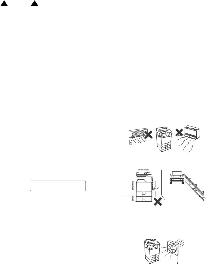
3. Note for installing site
Do not install the machine at the following sites.
-Place of high temperature, high humidity, low temperature, low humidity, place under an extreme change in temperature and humidity.
Paper may get damp and form condensation inside the machine, causing paper jam or copy dirt.
For operating and storing conditions, refer to the specifications described later.
-Place of extreme vibrations
It may cause a breakdown.
-Poorly ventilated place
An electrostatic type copier will produce ozone.
The quantity of ozone produced is designed to a low level so as not to affect human bodies. However, continuous use of such a machine may produce an ozone smell. Install the machine in a well ventilated place.
MX-M264U NOTE FOR SERVICING - i
-Place of direct sunlight.
Plastic parts and ink may be deformed, discolored, or may undergo qualitative change.
It may cause a breakdown or output quality problems.
-Place which is full of organic gases such as ammonium
The organic photo-conductor (OPC) drum used in the machine may undergo qualitative change due to organic gases such as ammonium.
Installation of this machine near a diazo-type copier and blue print machine may result in poor quality output.
-Place of much dust
When dust or contaminants enters the machine, it may cause a breakdown or poor quality output.
-Place near a wall
The machine will require ventilation.
If ventilation is not proper, poor output or machine failure may result.
11-13/16" (30cm)
11-13/16" |
17-23/32" |
(30cm) |
(45cm) |
-Unstable or irregular surface
If the machine is dropped or tips over, it may cause injury or machine malfunction.
Use an optional desk or an exclusive-use desk.
When using the optional desk, be sure to fix the adjuster and lock the casters.
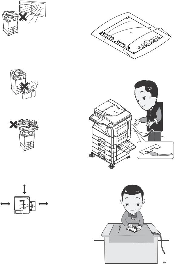
4.Note for handling PWB and electronic parts
When handling the PWB and the electronic parts, be sure to observe the following precautions in order to prevent against damage by static electricity.
-When in transit or storing, put the parts in an anti-static bag or an anti-static case and do not touch them with bare hands.
-When and after removing the parts from an anti-static bag (case), use an earth band as shown below:
- Put an earth band to your arm, and connect it to the machine.
-When repairing or replacing an electronic part, perform the procedure on an anti-static mat.
MX-M264U NOTE FOR SERVICING - ii

3 ‘13/Oct
5. Note for repairing/replacing the LSU
When repairing or replacing, be sure to observe the following items.
-When repairing or replacing the LSU, be sure to disconnect the power plug from the power outlet.
-When repairing or replacing the LSU, follow the procedures described in this Service Manual.
-When checking the operations after repairing the LSU, keep all the parts including the cover installed and perform the operation check.
-Do not modify the LSU.
-When visually checking the inside of the machine for the operation check, be careful not to allow laser beams to enter the eyes.
If the above precaution is neglected or the LSU is modified, ones safety may be at risk.
6.Note for handling the drum unit, the developing unit
When handling the OPC drum unit, and the developing unit, strictly observe the following items.
If these items are neglected, a trouble may be generated in the copy and print image quality.
Drum unit
-Avoid working at a place with strong lights.
-Do not expose the OPC drum to lights including interior lights for a long time.
-When the OPC drum is removed from the machine, cover it with light blocking material. (When using paper, use about 10 sheets of paper to cover it.)
-Be careful not to attach fingerprints, oil, grease, or other foreign material on the OPC drum surface.
Developing unit
-Be careful not to leave fingerprints, oil, grease, or other foreign material on the developing unit.
Fusing unit
-Be careful not to "leave" fingerprints, oil, grease, or other foreign material on the fusing roller.
If these items are neglected, a trouble may be generated in the copy and print image quality.
7. Screw tightening torque
The screws used in this machine are largely classified into three types.
These types are classified according to the shape of the screw grooves and use positions.
The table below shows the types of the screws and the tightening torques depending on the use position.
When tightening the screws for repair or maintenance, refer to the table.
However, for the other conditions of tightening screws than specified on this table, or under special circumstances, the details are described on the separate page. Refer to the descriptions on such an exception.
CAUTION:
Especially for the screw fixing positions where there is an electrode or a current flows, use enough care to tighten securely to avoid loosening.
Screw kinds and tightening torques
Normal screws, set screws (including step screws)
Screw |
Material to be |
Tightening |
Tightening |
Tightening |
||
torque |
torque |
torque |
||||
diameter |
fixed |
|||||
(N m) |
(kgf cm) |
(lbft) |
||||
|
|
|||||
M2.6 |
Steel plate |
0.8 - 1.0 |
8 - 10 |
0.6 - 0.7 |
||
M3 |
Steel plate |
1.0 - 1.2 |
10 |
- 12 |
0.7 - 0.9 |
|
M4 |
Steel plate |
1.6 - 1.8 |
16 |
- 18 |
1.2 - 1.3 |
|
Tapping screws (for iron) |
|
|
|
|
||
|
|
|
|
|
||
Screw |
Material to be |
Tightening |
Tightening |
Tightening |
||
torque |
torque |
torque |
||||
diameter |
fixed |
|||||
(N m) |
(kgf cm) |
(lbft) |
||||
|
|
|||||
M3 |
Steel plate |
1.0 - 1.2 |
10 |
- 12 |
0.7 - 0.9 |
|
|
(Plate thickness |
|
|
|
|
|
|
0.8mm or above) |
|
|
|
|
|
M4 |
Steel plate |
1.6 - 1.8 |
16 |
- 18 |
1.2 - 1.3 |
|
|
(Plate thickness |
|
|
|
|
|
|
0.8mm or above) |
|
|
|
|
|
M3 |
Steel plate |
0.6 - 0.8 |
6 |
- 8 |
0.4 - 0.6 |
|
|
(Plate thickness |
|
|
|
|
|
|
less than 0.8mm) |
|
|
|
|
|
M4 |
Steel plate |
1.2 - 1.4 |
12 |
- 14 |
0.9 - 1.0 |
|
|
(Plate thickness |
|
|
|
|
|
|
less than 0.8mm) |
|
|
|
|
|
Tapping screw (for plastic) |
|
|
|
|
||
|
|
|
|
|
||
Screw |
Material to be |
Tightening |
Tightening |
Tightening |
||
torque |
torque |
torque |
||||
diameter |
fixed |
|||||
(N m) |
(kgf cm) |
(lbft) |
||||
|
|
|||||
M3 |
Plastic resin |
0.6 - 0.8 |
6 |
- 8 |
0.4 - 0.6 |
|
M4 |
Plastic resin |
1.0 - 1.2 |
10 |
- 12 |
0.7 - 0.9 |
|
8.Relation between model names and names in the manual
Model name |
Name in the manual |
2 |
MX-M264U/MX-M264N/MX-M264NV/ |
26cpm machine |
3 |
MX-M264NR |
|
|
MX-M314U/MX-M314N/MX-M314NV/ |
31cpm machine |
|
MX-M314NR |
|
|
MX-M354U/MX-M354N//MX-M354NR |
35cpm machine |
|
MX-M264U NOTE FOR SERVICING - iii

2 2013.8.23 |
3 ‘13/Oct |
2 [1] PRODUCT OUTLINE
3 |
1. |
System configuration |
|
|
|
|
|
|
|
|
|
|
|||
|
|
-8 20 |
|
|
-8 62 |
|
|
|
|
2%6%23).'23).',% 0!33 |
|
|
$/#5-%.4 #/6%2 |
||
|
|
&%%$%2 |
|
|
|
|
|
|
|
|
|
|
-8 - 5 - 5 - 5 |
|
|
|
|
|
|
|
-8 - . - . - . |
|
|
|
|
-8 42 |
|
-8 - .2 - .2 - .2 |
|
||
|
|
-8 - .6 - .6 |
$)')4!, -5,4)&5.#4)/.!, |
|
|||
|
|
*/"/3%0!2!4/2 |
|
||||
|
|
|
3934%- |
|
|
||
|
|
|
|
$)')4!, -5,4)&5.#4)/.!, |
|
|
|
|
|
|
|
|
|
|
|
|
|
|
|
3934%- |
|
|
|
|
|
|
|
|
|
-8 4% |
|
|
|
|
|
|
|
%8)4 42!995.)4 |
|
|
|
-8 &. |
|
|
|
|
|
|
|
&).)3(%2 |
|
|
|
|
|
|
|
|
|
-8 $% |
|
|
|
|
|
|
|
3(%%4 0!0%2 |
|
|
|
|
|
|
|
$2!7%2 FOR TRAY |
|
|
|
|
|
|
|
|
-8 $% |
-8 $% |
|
|
|
|
-8 $3 |
X 3(%%4 0!0%2 |
3(%%4 0!0%2 |
|
|
|
|
|
()'( 34!.$ |
$2!7%2 |
$2!7%2 |
|
|
|
|
|
|
|
|
||
|
|
|
|
|
-8 $3 |
|
|
|
|
|
|
|
,/7734!.$ |
|
|
|
|
-8 0" |
-8 0+ |
-8 0& |
-8 .38 |
-8 &8 |
-8 &78 |
|
|
02).4%2.%80!.3)/. +)4 |
03 3%80!.3)/. +)4 |
"!2#/$%#&/.4 +)4 |
.%47/2+23#!..%2 |
&!#3)-),%-%80!.3)/. |
).4%2.%4 &!8 %80!.3)/. |
|
|
|
|
|
%80!.3)/. +)4 |
+)4 |
+)4) |
|
|
!2 35 |
-8 &2 &2 5 |
-8 538 |
-8 538 |
-8 53 |
-8 53 |
|
|
34!-0-5.)4 |
$!4!!3%#52)49 +)4 |
3(!20$%3+0 $,)#%.3% |
3(!20$%3+0 $,)#%.3% |
3(!20$%3+0 ,)#%.3% |
3(!20$%3+0 ,)#%.3% |
|
|
|
|
+)4 |
+)4 |
+)4 |
+)4 |
|
|
-8 53! |
-8 5. ! |
-8 5. ! |
-8 5. ! |
-8 5. ! |
-8 5. (! |
|
|
3(!20$%3+0 %,)#%.3% |
3HARPP/3!/.ETWORKK3CANNER |
3HARPP/3!/.ETWORKK3CANNER |
3HARPP/3!/.ETWORKK3CANNER |
3HARPP/3!/.ETWORKK3CANNER |
3HARPP/3!/.ETWORKK3CANNER |
|
|
+)4 |
4OOLO L,ICENSE,+IT |
4OOLO L,ICENSE,+IT |
4OOLO ,ICENSE +IT |
4OOLO ,ICENSE +IT |
4OOLO ,ICENSE +IT |
|
|
-8 !-8 |
-8 !-8 |
-8 !-8 |
-8 3#8 |
!2 36 |
-8 ($ ($ 2 |
|
|
!00,)#!4)/. |
!00,)#!4)/. |
%84%2.!, !##/5.4 |
34!0,% #!242)$'% |
34!-0-#!242)$'% |
(!2$ $)3+ %80!.3)/. +)4 |
|
|
).4%'2!4)/. -/$5,% |
#/--5.)#!4)/. -/$5,% -/$5,% |
|
|
|
|
|
|
-8 ($ |
-8 +" |
|
|
|
|
|
|
(!2$ $)3+ %80!.3)/. +)4 |
+%9"/!2$ |
|
|
|
|
|
|
|
|
MX-M264U PRODUCT OUTLINE 1 – 1 |
|
|
|

3 ‘13/Oct
2 [2] Option list |
|
|
|
3 |
|
|
||
|
|
|
|
|
|
|
|
|
|
|
|
|
|
|
|
|
|
|
|
|
|
MX-M264U |
MX-M264N |
MX-M264NR |
MX-M264NV |
Rema |
|
|
Model name |
Name |
MX-M314U |
MX-M314N |
MX-M314NR |
||
|
|
MX-M314NV |
rks |
|||||
|
|
|
|
MX-M354U |
MX-M354N |
MX-M354NR |
||
|
|
|
|
|
|
|||
|
Document |
MX-RP15 |
REVERSING SINGLE PASS FEEDER |
OPT |
STD |
STD |
STD |
|
|
feed system |
MX-VR11 |
DOCUMENT COVER |
OPT |
--- |
--- |
--- |
|
|
Paper feed |
MX-DE17 |
500 SHEET PAPER DRAWER |
OPT |
OPT |
OPT |
OPT |
|
|
system |
MX-DE18 |
2x500 SHEET PAPER DRAWER |
OPT |
OPT |
OPT |
OPT |
|
|
|
MX-DE24 |
500 SHEET PAPER DRAWER |
STD |
STD |
STD |
OPT*7 |
|
|
|
MX-DS16 |
LOW STAND |
OPT |
OPT |
OPT |
OPT |
|
|
|
MX-DS17 |
HIGH STAND |
OPT |
OPT |
OPT |
OPT |
|
|
Paper exit |
MX-TE10 |
EXIT TRAY UNIT |
OPT |
OPT |
OPT |
OPT |
*1 |
|
system |
MX-TR11 |
JOB SEPARATOR |
OPT |
OPT |
OPT |
OPT |
*2 |
|
|
MX-FN23 |
FINISHER |
OPT |
OPT |
OPT |
OPT |
*3 |
|
Printer expan- |
MX-PB15 |
PRINTER EXPANSION KIT |
OPT |
STD |
STD |
STD |
|
|
sion |
MX-PK11 |
PS3 EXPANSION KIT |
OPT |
OPT |
OPT |
OPT |
*4 |
|
|
MX-PF10 |
BARCODE FONT KIT |
OPT |
OPT |
OPT |
OPT |
*4 |
|
Image send |
MX-NSX1 |
NETWORK SCANNER EXPANSION KIT |
OPT |
STD |
STD |
STD |
|
|
expansion |
MX-FX11 |
FACSIMILE EXPANSION KIT |
OPT |
OPT |
OPT |
OPT |
|
|
|
MX-FWX1 |
INTERNET FAX EXPANSION KIT |
OPT |
OPT |
OPT |
OPT |
*5 |
|
|
AR-SU1 |
STAMP UNIT |
OPT |
OPT |
OPT |
OPT |
|
|
Authentica- |
MX-FR37/37U |
DATA SECURITY KIT |
OPT |
OPT |
--- |
--- |
*5 |
|
tion/Security |
|
|
|
|
|
|
|
|
|
|
|
|
|
|
|
|
|
Application/ |
MX-USX1 |
SHARPDESK 1 L2 CENSE KIT |
OPT |
OPT |
OPT |
OPT |
|
|
Solution |
MX-USX5 |
SHARPDESK 5 LICENSE KIT |
OPT |
OPT |
OPT |
OPT |
|
|
|
|
||||||
|
|
MX-US10 |
SHARPDESK 10 LICENSE KIT |
OPT |
OPT |
OPT |
OPT |
|
|
|
MX-US50 |
SHARPDESK 50 LICENSE KIT |
OPT |
OPT |
OPT |
OPT |
|
|
|
MX-USA0 |
SHARPDESK 100 LICENSE KIT |
OPT |
OPT |
OPT |
OPT |
|
|
|
MX-UN01A |
Sharp OSA Network Scanner Tool 1 License Kit |
OPT |
OPT |
OPT |
OPT |
*6 |
|
|
MX-UN05A |
Sharp OSA Network Scanner Tool 5 License Kit |
OPT |
OPT |
OPT |
OPT |
*6 |
|
|
MX-UN10A |
Sharp OSA Network Scanner Tool 10 License Kit |
OPT |
OPT |
OPT |
OPT |
*6 |
|
|
MX-UN50A |
Sharp OSA Network Scanner Tool 50 License Kit |
OPT |
OPT |
OPT |
OPT |
*6 |
|
|
MX-UN1HA |
Sharp OSA Network Scanner Tool 100 License Kit |
OPT |
OPT |
OPT |
OPT |
*6 |
|
|
MX-AMX1 |
APPLICATION INTEGRATION MODULE |
OPT |
OPT |
OPT |
OPT |
*5 |
|
|
MX-AMX2 |
APPLICATION COMMUNICATION MODULE |
OPT |
OPT |
OPT |
OPT |
*5 |
|
|
MX-AMX3 |
EXTERNAL ACCOUNT MODULE |
OPT |
OPT |
OPT |
OPT |
*5 |
|
Service |
MX-SCX1 |
STAPLE CARTRIDGE |
OPT |
OPT |
OPT |
OPT |
|
|
|
AR-SV1 |
STAMP CARTRIDGE |
OPT |
OPT |
OPT |
OPT |
|
|
Other |
MX-HD12 |
HARD DISK EXPANSION KIT |
OPT |
OPT |
OPT |
OPT |
|
|
|
MX-HD12R |
HARD DISK EXPANSION KIT |
--- |
--- |
OPT |
--- |
|
|
|
MX-HD13 |
HARD DISK EXPANSION KIT |
--- |
--- |
--- |
OPT |
|
|
|
MX-KB14 |
KEYBOARD |
--- |
--- |
--- |
OPT |
|
STD: Standard equipment OPT: Installable option
*1: The FINISHER is required.
*2: Cannot be installed the EXIT TRAY UNIT and the FINISHER concurrently. *3: Cannot be installed the JOB SEPARATOR concurrently.
*4: PRINTER EXPANSION KIT is required.
*5: HARD DISK EXPANSION KIT is required.
*6: APPLICATION COMMUNICATION MODULE is required.
*7: 500 Sheet Paper Drawer (for tray2:MX-DE24) is required for 1 tray model.
MX-M264U PRODUCT OUTLINE 1 – 2

2 2013.8.23
[2] SPECIFICATIONS
1. Basic specifications
A. Engine Specification
Photo conductor |
OPC (Diameter: 30mm) |
Recording |
Electronic photo (Laser) |
Development |
Dry-type dual-component magnetic |
|
brush development |
Charging |
Charged saw-tooth method |
Transfer |
Transfer roller |
Separation |
Separation claw method |
Cleaning |
Counter blade |
Fusing |
Heat roller |
Waste toner disposal |
Toner cartridge collection |
Toner supply during operation |
N/A |
Outer color |
Pastel white (Natural wave pattern) |
B. Engine speed (ppm)
Tray 1 - 4
Paper size |
26cpm |
31cpm |
35cpm |
|
machine |
machine |
machine |
||
|
||||
A3 |
15 |
17 |
20 |
|
11" x 17" |
14 |
17 |
19 |
|
8K |
16 |
19 |
21 |
|
B4, 8.5" x 13" |
16 |
20 |
22 |
|
8.5" x 14" |
16 |
20 |
22 |
|
A4, B5, 8.5" x 11", 5.5" x 8.5", 16K, A5 |
26 |
31 |
35 |
|
(B5 cannot be applied to the 2-stage |
|
|
|
|
paper feed tray.) |
|
|
|
|
A4R, 16KR, 8.5" x 11"R, |
18 |
24 |
27 |
|
B5R |
21 |
24 |
30 |
Manual paper feed
Paper size |
26cpm |
31cpm |
35cpm |
|
machine |
machine |
machine |
||
|
||||
A3 |
14 |
17 |
18 |
|
11" x 17" |
14 |
16 |
17 |
|
8K |
15 |
18 |
19 |
|
B4 |
16 |
19 |
20 |
|
8.5" x 13" |
17 |
20 |
22 |
|
8.5" x 13.5", 8.5" x 13.4" |
16 |
19 |
21 |
|
8.5" x 14" |
16 |
19 |
20 |
|
A4, B5, 8.5" x 11", 5.5" x 8.5", 16K, A5 |
23 |
27 |
29 |
|
A4R, 8.5" x 11"R, |
19 |
22 |
24 |
|
B5R |
21 |
24 |
26 |
|
A6R |
23 |
27 |
29 |
|
Extra |
14 |
16 |
17 |
|
Custom |
14 |
16 |
17 |
C. Printable area
A3 Wide |
N/A |
16K |
187 x 262mm |
A3 |
289 x 412mm |
12 x 18 |
N/A |
B4 |
242 x 356mm |
11" x 17" |
271 x 424mm |
A4 |
202 x 289mm |
8.5" x 14" |
208 x 348mm |
B5 |
168 x 249mm |
8.5" x 13" |
208 x 322mm |
A5 |
140 x 202mm |
Executive |
183 x 259mm |
A6R |
92 x 140mm |
8.5" x 11" |
208 x 271mm |
8K |
262 x 382mm |
5.5" x 8.5" |
132 x 208mm |
8.5" x 13.5" |
212 x 336mm |
8.5" x 13.4" |
212 x 333mm |
Custom |
Min.: 96mm x 141mm; Max.: 297mm x 432mm |
||
|
|
|
|
Max. range |
AB system: 416 x 293mm |
|
|
|
(When the resolution is 600dpi: 9826dot x 6920dot) |
||
|
Inch system: 428 x 275mm |
|
|
|
(When the resolution is 600dpi: 10110dot x 6496dot) |
||
Void Area / |
Top: 4mm or less |
|
|
Image Loss |
Bottom: 4mm or less |
|
|
|
FR total: 6mm or less |
|
|
D. Engine resolution
Resolution*1 |
Copy |
Writing |
|
|
600 x 600dpi |
|
Writing |
|
|
|
600 x 600dpi |
|
|
1,200 x 600dpi (PCL/PS) |
Gradation *2 |
Copy |
Writing |
(256 levels) |
|
600 x 600dpi x 1bit |
|
Writing |
|
|
|
Sharp Advanced Printing Language: |
|
|
600 x 600dpi x 1bit |
|
|
PCL: |
|
|
600 x 600dpi x 1bit |
|
|
1,200 x 600dpi x 1bit |
|
|
PS: |
|
|
600 x 600dpi x 1bit |
|
|
1,200 x 600dpi x 1bit |
*1: Resolution: 600dpi (default)
*2: The dither and error diffusion methods using 8bit input will be performed.
E. Scanner section
(1)Resolution/Gradation
Scanning |
|
Monochrome |
Resolution (dpi) |
Platen |
600 x 600dpi |
|
|
600 x 400dpi |
|
|
600 x 300dpi (default) |
|
RSPF |
600 x 600dpi |
|
|
600 x 400dpi (default) |
Exposure lamp |
White LED |
|
Reading gradation |
10bit |
|
Output gradation |
BW: 1bit |
|
|
Grayscale: 8bit |
|
|
Full Color: each color RGB 8bit |
|
(2)Document table
Type |
Document table fixed system (Flat bed) |
|
Scanning area |
297 x 432mm |
|
Original standard |
Left rear reference |
|
position |
|
|
Detection |
Yes |
|
Detection size |
Automatic detection (Detection types can be |
|
|
changed in the system settings) |
|
Dehumidifying |
Supplied as a service parts |
|
heater |
|
|
(Scanner section) |
|
|
F. Document feeder |
|
|
|
|
|
Type |
RSPF (Reversing single pass feeder) |
|
Scan speed |
Monochrome |
Color (A4/8.5" x 11") |
|
(A4/8.5" x 11") |
|
Copy |
Single: |
NA |
|
50-sheet/min. |
|
|
(600 x 400dpi, 4bit) |
|
|
36-sheet/min. |
|
|
(600 x 600dpi, 4bit) |
|
|
Double: |
|
|
20-page/min. |
|
|
(600 x 400dpi, 4bit) |
|
|
17-page/min. |
|
|
(600 x 600dpi, 4bit) |
|
FAX |
Single: 50-sheet/min. |
NA |
|
(200 x 200dpi, 1bit) |
|
|
Double: 20-page/min. |
|
|
(200 x 200dpi, 1bit) |
|
Internet FAX |
Single: 50-sheet/min. |
NA |
|
(200 x 200dpi, 1bit) |
|
|
Double: 20-page/min. |
|
|
(200 x 200dpi, 1bit) |
|
MX-M264U SPECIFICATIONS 2 – 1
Scanner |
Single: 50-sheet/min. |
Single: 50-sheet/min. |
||
|
(200 x 200dpi, 1bit) |
(200 x 200dpi, 8bit) |
||
|
Double: 20-page/min. |
Double: 20-page/min. |
||
|
(200 x 200dpi, 1bit) |
(200 x 200dpi, 8bit) |
||
Original setup |
Upward standard (1 to N feeding standard) |
|||
direction |
|
|
|
|
Original standard |
Center standard (Rear one-side standard for |
|||
position |
random feeding) |
|
||
Original transport |
Sheet-through method |
|
||
method |
|
|
|
|
Original size |
Standard size |
|
||
|
Inch-1: 11" x 17", 8.5" x 14", 8.5" x 11", 8.5" x 11"R, |
|||
|
|
5.5" x 8.5", A3, A4 |
||
|
Inch-2: 11" x 17", 8.5" x 13", 8.5" x 11", 8.5" x 11"R, |
|||
|
|
5.5" x 8.5", A3, A4 |
||
|
Inch-3: 11" x 17", 8.5" x 13.4", 8.5" x 11", |
|||
|
|
8.5" x 11"R, 5.5" x 8.5", A3, A4 |
||
|
AB-1: |
11" x 17", 8.5" x 14", 8.5" x 11", A3, B4, A4, |
||
|
|
A4R, B5, B5R, A5 |
||
|
AB-2: |
11" x 17", 8.5" x 13", 8.5" x 11", A3, B4, A4, |
||
|
|
A4R, B5, B5R, A5 |
||
|
AB-3: |
11" x 17", 8.5" x 13", 8.5" x 11", A3, B4, A4, |
||
|
|
A4R, A5, 8K, 16K, 16KR |
||
|
AB-4: |
11" x 17", 8.5" x 13.4", 8.5" x 11", A3, B4, A4, |
||
|
|
A4R, B5, B5R, A5 |
||
|
AB-5: |
11" x 17", 8.5" x 13.5", 8.5" x 11", A3, B4, A4, |
||
|
|
A4R, B5, B5R, A5 |
||
|
Long |
|
1000 mm (Monochrome binary only) |
|
|
paper |
|
Internet Fax 600 x 600 dpi: Max. 800 mm. |
|
|
|
|
When scan 400 dpi or more, long paper |
|
|
|
|
is not available. |
|
Mix paper feed |
Enabled |
|
||
(Same series, |
|
|
|
|
same width paper) |
|
|
|
|
Random feeding |
Enabled |
|
||
(feeding of different |
Only the following combinations of 2 size types are |
|||
types / different |
allowed: |
|
||
widths) |
A3 and B4; B4 and A4R; A4 and B5; B5 and A5; |
|||
|
and 11-inch and 8.5-inch. AMS available. 2-sided |
|||
|
scanning is disabled during random feeding. |
|||
Original copy |
Single: |
|
|
|
weight |
Thin paper: 9 - 13 lb bond (35 - 49 g/m2) |
|||
|
Plain paper: 13 - 32 lb bond (50 - 128 g/m2) |
|||
|
* Thin paper mode (39 pages/minute |
|||
|
(A4, 8.5" x 11", 600 x 400dpi) / 26 pages/minute |
|||
|
(A4, 8.5" x 11", 600 x 600dpi) is set up for the thin |
|||
|
paper. |
|
||
|
Duplex: 13 - 28 lb bond (50 - 105 g/m2) |
|||
Max. loading |
Max. 100 sheets (21lbs Bond, 80g/m2), or Max. |
|||
capacity of |
height: 1/2 inch, 13mm or less |
|||
documents |
|
|
|
|
Un-acceptable |
Transparency, second original paper, tracing paper, |
|||
originals for |
carbon paper, thermal paper, paper with wrinkles, |
|||
feeding. |
folds, or breakage, pasted paper, cutout document, |
|||
|
document printed with ink ribbon, documents with |
|||
|
perforation other than 2- or 3-holes (Perforated |
|||
|
document by punch unit is allowed.) |
|||
Detection |
Yes |
|
|
|
Paper detection |
Auto detection |
|
||
size |
Inch-1: 11" x 17", 8.5" x 14", 8.5" x 11", 8.5" x 11"R, |
|||
|
|
5.5" x 8.5", A3, A4 |
||
|
Inch-2: 11" x 17", 8.5" x 13", 8.5" x 11", 8.5" x 11"R, |
|||
|
|
5.5" x 8.5", A3, A4 |
||
|
Inch-3: 11" x 17", 8.5" x 13.4", 8.5" x 11", |
|||
|
|
8.5" x 11"R, 5.5" x 8.5", A3, A4 |
||
|
AB-1: |
11" x 17", 8.5" x 14", 8.5" x 11", A3, B4, A4, |
||
|
|
A4R, B5, B5R, A5 |
||
|
AB-2: |
11" x 17", 8.5" x 13", 8.5" x 11", A3, B4, A4, |
||
|
|
A4R, B5, B5R, A5 |
||
|
AB-3: |
11" x 17", 8.5" x 13", 8.5" x 11", A3, B4, A4, |
||
|
|
A4R, A5, 8K, 16K, 16KR |
||
|
AB-4: |
11" x 17", 8.5" x 13.4", 8.5" x 11", A3, B4, A4, |
||
|
|
A4R, B5, B5R, A5 |
||
|
AB-5: |
11" x 17", 8.5" x 13.5", 8.5" x 11", A3, B4, A4, |
||
|
|
A4R, B5, B5R, A5 |
||
Paper feeding |
Right hand feeding |
|
||
direction |
|
|
|
|
Finish stamp |
Option |
|
|
|
Reliability |
MCBJ/MCBF: Same as the main unit |
Life |
Same as the main unit |
Power Source |
Provided from the main unit |
Dimensions |
W 580 x D 465 x H 155 mm, W 22-54/64 x D 18-20/ |
|
64 x H 6-7/64 in. |
Weight |
Approx. 7.3kg, Approx. 16.1 lbs |
Outer color |
Warm gray/ Pastel white (2 toned color) |
Optional detection |
Auto detection supported |
Installation / |
Should be installed by the service technician easily |
Maintenance |
|
Packaged items |
Glass cleaner (must be storable in the RSPF) |
G. Paper feed section
(1)Basic specifications
Type |
|
Standard |
|
2-stage paper feed tray + multi manual paper feed |
||||
|
|
|
|
|
tray |
|
|
|
|
|
Full option |
|
4-stage paper feed tray + multi manual paper feed |
||||
|
|
|
|
|
tray |
|
|
|
Dehumidifying |
|
N/A |
|
|
|
|||
heater |
|
|
|
|
|
|
|
|
|
|
|
|
|
|
|
|
|
|
Tray |
|
Tray 1 |
|
Tray 2 |
Multi |
||
|
|
|
Bypass Tray |
|||||
|
|
|
|
|
|
|
|
|
Paper |
|
Standard |
|
500 sheets |
|
500 sheets |
100 sheets |
|
capacity |
|
paper |
|
|
|
|
|
|
|
|
|
(80g/m2) |
|
|
|
|
|
Paper size |
|
Refer to “Size of paper which can be fed”. |
||||||
Paper size detection |
|
|
No |
Yes |
||||
|
|
|
|
|
(Guide adjustment and size input) |
|
||
Paper type setting |
|
Refer to “Size of paper which can be fed”. |
||||||
Changing of paper |
|
Switched by the user |
Switched by |
|||||
size |
|
|
|
|
|
|
the user |
|
|
|
|
|
|
|
|
|
(Guide |
|
|
|
|
|
|
|
|
adjustment) |
Universal handle |
|
|
Yes |
- |
||||
Default |
|
Inch |
|
8.5" x 11" |
- |
|||
paper |
|
system |
|
|
|
|
|
|
size |
|
AB |
|
|
A4 |
- |
||
setting |
|
system |
|
|
|
|
|
|
Detection of |
|
N/A (Only paper availability is detected) |
||||||
remaining paper |
|
|
|
|
|
|||
Paper size display |
|
|
Yes |
- |
||||
window |
|
|
|
|
|
|
|
|
(2)Extra paper capacity
Paper type |
Paper feed tray |
Manual feed tray |
Envelope |
NA |
AB system: 10 sheets |
|
|
Inch system: 5 sheets |
Transparency |
NA |
40 sheets |
Heavy paper |
NA |
30 sheets (Max. 200g/m2) |
Tab paper |
NA |
30 sheets (Target) |
Others |
NA |
1 sheet |
MX-M264U SPECIFICATIONS 2 – 2

(3) Size of paper which can be fed
|
|
|
|
Paper Feeding Section |
|
Bypass |
|
|
|
|
Standard Tray |
Optional Tray |
|||
|
|
|
Tray |
||||
|
|
|
Tray 1 |
Tray 2*6 |
Tray 3 |
Tray 4 |
|
|
|
|
|
||||
Paper Size |
12 x 18 (A3W) |
|
- |
- |
- |
- |
- |
|
11" x 17" |
|
Yes |
Yes |
Yes |
Yes |
Yes |
|
8.5" x 14" (216 x 356) |
|
Yes |
Yes |
Yes |
Yes |
Yes |
|
8.5" x 13.5" (216 x 343) |
|
Yes*5 |
Yes*5 |
Yes*5 |
Yes*5 |
Yes*5 |
|
8.5" x 13.4" (216 x 340) |
|
Yes*5 |
Yes*5 |
Yes*5 |
Yes*5 |
Yes*5 |
|
8.5" x 13" (216 x 330) |
|
Yes |
Yes |
Yes |
Yes |
Yes |
|
8.5" x 11" |
|
Yes |
Yes |
Yes |
Yes |
Yes |
|
8.5" x 11"R |
|
Yes |
Yes |
Yes |
Yes |
Yes |
|
7.25 x 10.5R |
|
- |
- |
- |
- |
Yes |
|
5.5" x 8.5" |
|
Yes |
- |
- |
- |
Yes |
|
5.5" x 8.5"R |
|
- |
- |
- |
- |
Yes |
|
A3 |
|
Yes |
Yes |
Yes |
Yes |
Yes |
|
B4 |
|
Yes |
Yes |
Yes |
Yes |
Yes |
|
A4 |
|
Yes |
Yes |
Yes |
Yes |
Yes |
|
A4R |
|
Yes |
Yes |
Yes |
Yes |
Yes |
|
B5 |
|
Yes |
- |
Yes |
Yes |
Yes |
|
B5R |
|
Yes |
Yes |
Yes |
Yes |
Yes |
|
A5R |
|
- |
- |
- |
- |
Yes |
|
A5 |
|
Yes |
- |
- |
- |
Yes |
|
B6R |
|
- |
- |
- |
- |
Yes |
|
8K |
|
Yes |
Yes |
Yes |
Yes |
Yes |
|
16K |
|
Yes |
? |
Yes |
Yes |
Yes |
|
16KR |
|
Yes |
Yes |
Yes |
Yes |
Yes |
|
A6R |
|
- |
- |
- |
- |
Yes |
|
Envelope*1 |
|
- |
- |
- |
- |
Yes |
|
Custom*2 |
|
- |
- |
- |
- |
Yes |
Paper Type |
Thin paper |
13 - 16 lb bond (56 - 59g/m2) |
Yes |
Yes |
Yes |
Yes |
Yes |
|
Plain paper |
16 - 28 lb bond (60 - 105g/m2) |
Yes |
Yes |
Yes |
Yes |
Yes |
|
|
Recycled paper |
Yes |
Yes |
Yes |
Yes |
Yes |
|
|
Color paper |
Yes |
Yes |
Yes |
Yes |
Yes |
|
|
Letter head |
Yes |
Yes |
Yes |
Yes |
Yes |
|
|
Pre-printed |
Yes |
Yes |
Yes |
Yes |
Yes |
|
|
Pre-punched |
Yes |
Yes |
Yes |
Yes |
Yes |
|
Heavy paper |
28 lb bond - 110 lb index (106 - 200g/m2) |
- |
- |
- |
- |
Yes |
|
|
110 lb index - 140 lb index (201 - 256g/m2) |
- |
- |
- |
- |
- |
|
Envelope |
75-90g/m2 |
- |
- |
- |
- |
Yes |
|
Transparency |
|
- |
- |
- |
- |
Yes |
|
Label*3 |
|
- |
- |
- |
- |
Yes |
|
Tab paper*4 |
|
- |
- |
- |
- |
Yes |
|
User settings 1-7 |
|
Yes |
Yes |
Yes |
Yes |
Yes |
*1: Supported envelop types: Monarch/Com-10/DL/C5/Custom
* Custom envelope size is configurable by Sim setting (default: hidden) *2: Custom size
|
|
AB system (mm) |
Inch system (inch) |
||
|
|
Min. |
Max. |
Min. |
Max. |
Bypass tray |
X |
140 |
432 |
5-1/2 |
17 |
|
Y |
100 |
297 |
5-1/2 |
11-5/8 |
Long size paper from the bypass tray: max. 1,200mm is configurable by Sim. *3: Supported label paper: SF-4A3F
*4: Supported tab paper: A4 tab width: 12 - 20mm
8.5" x 11" tab width: 6.1 - 17mm *5: Need to set from Sim
2 *6: Tray2 is not standard for MX-264NV/314NV.
MX-M264U SPECIFICATIONS 2 – 3
H. Paper exit section
(1) |
Exit Capacity |
|
|
|
|
|
|
|
|
|
|
|
|
|
|
|
|
|
Output Location |
Center |
|
Job Separator |
|
|
Right Side (Option) |
|
Output Method |
Face down |
|
|
|
|
|
|
|
Output Capacity |
500 sheets (80g/m2) |
|
Upper tray: 100 sheets (80g/m2) |
|
100 sheets (80g/m2) |
|||
|
|
|
|
Lower tray: 500 sheets (80g/m2) |
|
|
|
|
Output paper size / weight |
Refer to “Size of paper which can be discharged”. |
|
|
|
|
|||
Shifting function |
Yes |
|
No |
|
|
|
|
|
Output paper detection |
Yes |
|
No |
|
|
|
|
|
Exit tray full detection |
No |
|
Yes |
|
|
|
|
|
(2) |
Shifter |
|
|
|
|
|
|
|
|
|
|
|
|
|
|
|
|
Type |
Shifter |
|
|
|
|
|
|
|
Paper size |
Non-offset (Normal output) |
Refer to “Size of paper which can be discharged”. |
|
|
||||
|
|
Offset mode |
Refer to “Size of paper which can be discharged”. |
|
|
|||
Paper weight |
All usable paper |
|
|
|
|
|
|
|
Productivity |
Non-offset (Normal output) |
Same speed as the main unit (no speed loss) |
|
|
||||
* When A4/8.5" x 11" is used |
Offset mode |
Same speed as the main unit (no speed loss) |
|
|
||||
Offset range |
30mm |
|
|
|
|
|
|
|
Range of error |
|
Horizontal direction |
Vertical direction |
Between jobs |
||||
* When the recommended paper of |
Non-offset |
Not drop from the tray |
- |
|
|
- |
||
|
A4/8.5" x 11" is used |
Offset mode |
Within 50 mm |
Within 10mm |
|
10mm or more |
||
(3) Size of paper which can be discharged
|
|
|
|
|
Output Section |
|
|
|
|
|
Duplex |
|
Center Tray |
|
Right Exit |
|
|
|
|
Job |
|
||
|
|
|
|
Exit Tray |
Offset |
Tray |
|
|
|
|
|
Separator |
|||
|
|
|
|
|
|
|
|
Paper Size |
12 x 18 (A3W) |
|
- |
- |
- |
- |
- |
|
11" x 17" |
|
Yes |
Yes |
Yes |
Yes |
Yes |
|
8.5" x 14" (216 x 356) |
|
Yes |
Yes |
Yes |
Yes |
Yes |
|
8.5" x 13.5" (216 x 343) |
|
Yes |
Yes |
Yes |
Yes |
Yes |
|
8.5" x 13.4" (216 x 340) |
|
Yes |
Yes |
Yes |
Yes |
Yes |
|
8.5" x 13" (216 x 330) |
|
Yes |
Yes |
Yes |
Yes |
Yes |
|
8.5" x 11" |
|
Yes |
Yes |
Yes |
Yes |
Yes |
|
8.5" x 11"R |
|
Yes |
Yes |
Yes |
Yes |
Yes |
|
7.25 x 10.5R |
|
- |
Yes |
Yes |
Yes |
- |
|
5.5" x 8.5" |
|
- |
Yes |
Yes |
Yes |
- |
|
5.5" x 8.5"R |
|
- |
- |
- |
- |
- |
|
A3 |
|
Yes |
Yes |
Yes |
Yes |
Yes |
|
B4 |
|
Yes |
Yes |
Yes |
Yes |
Yes |
|
A4 |
|
Yes |
Yes |
Yes |
Yes |
Yes |
|
A4R |
|
Yes |
Yes |
Yes |
Yes |
Yes |
|
B5 |
|
Yes |
Yes |
Yes |
Yes |
Yes |
|
B5R |
|
Yes |
Yes |
Yes |
Yes |
Yes |
|
A5R |
|
- |
Yes |
- |
Yes |
- |
|
A5 |
|
Yes |
Yes |
Yes |
Yes |
- |
|
B6R |
|
? |
Yes |
- |
- |
- |
|
8K |
|
Yes |
Yes |
Yes |
Yes |
Yes |
|
16K |
|
Yes |
Yes |
Yes |
Yes |
Yes |
|
16KR |
|
Yes |
Yes |
Yes |
Yes |
Yes |
|
A6R |
|
- |
Yes |
Yes |
Yes |
- |
|
Envelope*1 |
|
- |
Yes |
Yes |
- |
- |
|
Extra |
|
- |
Yes |
Yes |
- |
- |
|
Custom*2 |
|
Yes |
Yes |
Yes |
- |
Yes |
MX-M264U SPECIFICATIONS 2 – 4
|
|
|
|
|
Output Section |
|
|
|
|
|
Duplex |
|
Center Tray |
|
Right Exit |
|
|
|
|
Job |
|
||
|
|
|
|
Exit Tray |
Offset |
Tray |
|
|
|
|
|
Separator |
|||
|
|
|
|
|
|
|
|
Paper Type |
Thin paper |
13-16 lb bond (55 - 59g/m2) |
- |
Yes |
Yes |
Yes |
Yes |
|
Plain paper |
16-28 lb bond (60 - 105g/m2) |
Yes |
Yes |
Yes |
Yes |
Yes |
|
|
Recycled paper |
Yes |
Yes |
Yes |
Yes |
Yes |
|
|
Color paper |
Yes |
Yes |
Yes |
Yes |
Yes |
|
|
Letter head |
Yes |
Yes |
Yes |
Yes |
Yes |
|
|
Pre-printed |
Yes |
Yes |
Yes |
Yes |
Yes |
|
|
Pre-punched |
Yes |
Yes |
Yes |
Yes |
Yes |
|
Heavy paper |
28 lb bond - 110 lb index |
- |
Yes |
Yes |
Yes |
- |
|
|
(106 - 200g/m2) |
|
|
|
|
|
|
|
110 lb index -140 lb index |
- |
- |
- |
- |
- |
|
|
(201 - 256g/m2) |
|
|
|
|
|
|
Envelope |
75 - 90g/m2 |
- |
Yes |
Yes |
- |
- |
|
Transparency |
|
- |
Yes |
Yes |
- |
- |
|
Label |
|
- |
Yes |
Yes |
- |
- |
|
Tab paper |
|
- |
Yes |
Yes |
- |
- |
|
User settings 1 - 7 |
|
Yes*3 |
Yes |
Yes |
Yes |
Yes |
*1: Supported Envelop types: Monarch/Com-10/DL /C5/Custom
Custom envelope size is supported by Sim. Not displayed at the default setting. *2: Custom size
|
|
AB System (mm) |
Inch System (inch) |
||
|
|
Min. |
Max. |
Min. |
Max. |
Bypass tray |
X |
140 |
432 |
5-1/2 |
17 |
|
Y |
100 |
297 |
5-1/2 |
11-5/8 |
Duplex |
X |
182 |
432 |
8-1/2 |
17 |
|
Y |
182 |
297 |
7-1/4 |
11-5/8 |
Long size paper (bypass tray only): support up to 1,200mm by Sim * Long size paper ejection is from center tray/inner finisher
*3: Comply to “Paper type setting”
*4: Can be input but array is not supported
*5: Can be input and stapled but array is not supported
*6: Array of heavy paper more than 130g/m2 is not supported
*7: Heavy paper can be stapled only in case of using as front and back cover page with other normal paper
MX-M264U SPECIFICATIONS 2 – 5
I. Operation panel
Size |
|
7 inch |
||
Form |
|
Dot matrix LCD, Touch panel |
||
Display dot number |
|
800 x 480 dots (WVGA) |
||
Color |
|
Yes |
||
LCD drive display area (W x D) |
152.4 x 91.44 |
|||
LCD backlight |
|
LED backlight |
||
LCD contrast adjust |
|
Yes |
||
Angle/position adjustment |
No tilting mechanism |
|||
J. Controller board |
|
|||
|
|
|
|
|
CPU |
|
ARM11: 600MHz |
|
|
|
|
|
ARM9: 400MHz/during 1W energy save mode: 75MHz |
|
Interface |
|
|
||
IEEE1284 |
|
No |
|
|
Parallel |
|
|
|
|
Ethernet |
|
1port |
|
|
|
Interface |
|
10Base-T, 100Base-TX, 1000Base-T |
|
|
Support |
|
TCP/IP (IPv4, IPv6), IPX/SPX, NetBEUI, EtherTalk |
|
|
Protocol |
|
|
|
USB 2.0 (high |
|
2port |
|
|
speed) (host)*1 |
|
(Simultaneous use of the front/rear ports is enable.) |
||
USB 2.0 (high |
|
1port |
|
|
speed) (device) |
|
|
|
|
USB-HUB (host) |
|
Internal: 4port |
|
|
|
|
|
? For Front USB Port |
|
|
|
|
? For Rear USB Port |
|
|
|
|
? Reserved |
|
|
|
|
? For the retractable keyboard |
|
USB certification |
|
No |
|
|
ACRE expansion |
|
No |
|
|
I/F |
|
|
|
|
Ir-Simple I/F |
|
No |
|
|
Video I/F |
|
No |
|
|
Serial I/F |
|
1port |
|
|
(For coin- |
|
(The port is on the electric board. D-Sub cable is |
||
operated |
|
provided as a service part.) |
||
machines/PCI) |
|
|
|
|
Memory |
|
See the section “Memory/Hard disk/SD card memory”. |
||
Windows |
|
No |
|
|
Premium Logo |
|
|
|
|
certification |
|
|
|
|
WHQL |
|
Yes |
|
|
certification |
|
|
|
|
*1: The USB port can be disabled by Sim
K. Memory/Hard disk/SD card memory
SD card |
ICU (Reus) PWB |
HDD*2 |
|
Memory*1 |
|||
|
|
||
8GB |
2GB |
OPT (160GB) |
*1: Memory expansion is not available
*2: HDD capacity depends on the procurement and sourcing status When an option HDD is installed, the SD card of 4GB is required.
Memory area |
Boot/Program area |
|
|
(SD card) |
FAX data storage area |
|
|
|
|
Without HDD |
With HDD |
|
|
512MB |
1GB |
L. Warm-up time |
|
||
|
|
|
|
Warm-up time |
20sec. or less |
|
|
Pre heat |
Yes |
|
|
Jam recovery time*1 |
10sec. or less |
|
|
* Result may change depending on conditions.
*1: Conditions: Leave the machine for 60 sec. after door open, standard condition, Polygon stops.
2. Copy functions
A. First copy time
Engine |
26cpm |
31cpm |
35cpm |
|
machine |
machine |
machine |
||
|
||||
Platen |
4.7 sec. |
4.3 sec. |
4.0 sec. |
|
RSPF |
7.5 sec. |
6.9 sec. |
6.5 sec. |
*Measuring Conditions
Feed the A4 (8-1/2 x 11) sheet in landscape from tray 1, with the polygon rotating condition.
Value might vary depends on the machine settings/conditions
B. Job Speed
Engine |
26cpm |
31cpm |
35cpm |
|
machine |
machine |
machine |
||
|
||||
S to S |
26cpm (100%) |
31cpm (100%) |
35cpm (100%) |
*Defines the copy speed of when the main unit and a document feeder are used in combination.
*S to S: copying 1 set of an 11-sheet original in A4 / 8.5" x 11" (not including the first copy)
Monochrome: 600 x 400dpi (default)
C. Job Effectiveness
BLI Standard (RSPF)
Engine |
26cpm |
31cpm |
35cpm |
|
machine |
machine |
machine |
||
|
||||
S to S |
25cpm (96.2%) |
28cpm (90.3%) |
33cpm (94.3%) |
|
S to D |
21cpm (80.8%) |
23cpm (74.2%) |
24cpm (68.6%) |
|
D to D |
20cpm (76.9%) |
22cpm (71.0%) |
23cpm (65.7%) |
*S to S: 10 pages of A4 / 8.5" x 11" document and 5 copies
*S to D: 10 pages of A4 / 8.5" x 11" document and 5 copies
*D to D: 10 pages (20 sides) of A4 / 8.5" x 11" document and 5 copies
MX-M264U SPECIFICATIONS 2 – 6
3. Printer function
A. Printer driver supported OS
|
|
|
|
Custom |
|
|
|
|
|
Sharp |
|
|
|
|
|
|
|
Custom |
Custom PS |
PPD |
Advanced |
PC-FAX |
TWAIN |
||
|
OS |
|
PCL6 |
|
||||||||
|
|
|
PCL5e |
Printing |
||||||||
|
|
|
|
SPDL2 |
|
|
|
|
|
|
||
|
|
|
|
|
|
|
|
|
Language |
|
|
|
|
|
|
|
|
|
|
|
|
|
|
|
|
Windows |
98 / Me |
|
No |
|
No |
No |
No |
No |
No |
No |
||
|
NT 4.0 SP5 or later |
|
No |
|
No |
No |
No |
No |
No |
No |
||
|
2000 |
|
|
No |
|
No |
No |
No |
No |
No |
No |
|
|
XP |
|
CD-ROM |
|
No |
CD-ROM |
CD-ROM |
CD-ROM |
CD-ROM |
CD-ROM |
||
|
XP x64 |
|
CD-ROM |
|
No |
CD-ROM |
CD-ROM |
CD-ROM |
CD-ROM |
CD-ROM |
||
|
Server 2003 |
|
CD-ROM |
|
No |
CD-ROM |
CD-ROM |
CD-ROM |
CD-ROM |
CD-ROM |
||
|
Server 2003 x64 |
|
CD-ROM |
|
No |
CD-ROM |
CD-ROM |
CD-ROM |
CD-ROM |
CD-ROM |
||
|
Vista |
|
CD-ROM |
|
No |
CD-ROM |
CD-ROM |
CD-ROM |
CD-ROM |
CD-ROM |
||
|
Vista x64 |
|
CD-ROM |
|
No |
CD-ROM |
CD-ROM |
CD-ROM |
CD-ROM |
CD-ROM |
||
|
Server 2008 |
|
CD-ROM |
|
No |
CD-ROM |
CD-ROM |
CD-ROM |
CD-ROM |
CD-ROM |
||
|
Server 2008 x64 |
|
CD-ROM |
|
No |
CD-ROM |
CD-ROM |
CD-ROM |
CD-ROM |
CD-ROM |
||
|
Windows 7 |
|
CD-ROM |
|
No |
CD-ROM |
CD-ROM |
CD-ROM |
CD-ROM |
CD-ROM |
||
|
Windows 7 x64 |
|
CD-ROM |
|
No |
CD-ROM |
CD-ROM |
CD-ROM |
CD-ROM |
CD-ROM |
||
Mac |
9.0-9.2.2 |
|
|
No |
|
No |
No |
No |
No |
No |
No |
|
|
X 10.2.8 |
|
No |
|
No |
No |
No |
No |
No |
No |
||
|
X 10.3.9 |
|
No |
|
No |
No |
No |
No |
No |
No |
||
|
X 10.4.11 |
|
No |
|
No |
No |
CD-ROM |
No |
No |
No |
||
|
X 10.5 - 10.5.8 |
|
No |
|
No |
No |
CD-ROM |
No |
Web |
No |
||
|
X 10.6 - 10.6.8 |
|
No |
|
No |
No |
CD-ROM |
No |
Web |
No |
||
|
X 10.7 - 10.7.2 |
|
No |
|
No |
No |
CD-ROM |
No |
Web |
No |
||
B. PDL emulation/Font |
|
|
|
|
|
|
|
|
|
|
||
|
|
|
|
|
|
|
|
|
|
|
|
|
|
PDL (Command) |
|
|
|
|
Installed font |
|
|
|
Option font |
|
|
PCL6 compatibility |
|
N model: STD |
European outline font = 80 styles |
|
|
Barcode font = 28 styles |
|
|||||
|
|
|
U model: OPT |
Line printer font (BMP) = 1 style |
|
|
|
|
|
|||
Postscript3 compatibility |
|
|
OPT |
|
|
- |
|
|
European outline font = 136 styles |
|
||
4. FAX function
A. Transmission method
Transmission time |
|
Less than 3 sec (Super G3) |
|
|
Less than 7 sec (G3 ECM) |
Compression/ |
|
MH, MR, MMR, JBIG |
expansion system |
|
(Fixed to ECM for MMR or JBIG.) |
Modem speed |
|
33.6kbps 2.4kbps automatic fallback |
Resolution |
|
8 x 3.85 line/mm, 8 x 7.7 line/mm, |
|
|
8.15.4 line/mm, 16 x 15.4 line/mm (Standard |
|
|
memory is used for transmit/receive.) |
Intercommunication |
|
G3/Super G3: Standard (V.34, V.17, V.33, V.29, |
|
|
V.27ter) |
Communication line |
|
General telephone line (PSTN), ISDN (When TA |
|
|
is installed.) Private Branch Exchange (PBX) |
ECM |
|
Yes |
B. Number of Support Line |
||
|
|
|
Standard |
|
1 line |
Expansion |
|
Not provided |
D. Image Quality/Image Process
Half tone reproduction |
Equivalent to 256 levels (Valid only when |
|
monochrome document is scanned.) |
Exposure adjustment |
Auto / Manual (5 steps) |
FAX quality selection |
Standard (8 x 3.85 lines/mm (203.2 x 97.8dpi)) |
|
Fine (8 x 7.7 lines/mm (203.2 x 195.6dpi)) |
|
Super Fine (8 x 15.4 lines/mm (203.2 x 391dpi)) |
|
Ultra Fine (16 x 15.4 lines/mm (406.4 x 391dpi)) |
|
Half-tone (Combination with normal character is |
|
invalid.) |
E. Record Size |
|
|
|
Max. record width |
293mm |
Record size |
(AB series) |
|
A3, B4, A4, A4R, B5, B5R, A5R |
|
(Inch series) |
|
11" x 17", 8.5" x 13", 8.5" x 14", 8.5" x 11", |
|
8.5" x 11"R, 8.5 x 5.5R |
*If the document length exceeds A3 size, it is divided and printed.
*For printing the list, A5R and 8.5" x 5.5"R cannot be used.
C. Transmission Mode
RSPF/OC |
Yes (Switching during the reading is not feasible) |
transmission switching |
|
MX-M264U SPECIFICATIONS 2 – 7
F. |
Dial |
|
|
|
|
|
|
|
|
|
|
||
Manual dialing |
To be entered by 10-key, # key, * key |
|||||
Re-dialing |
|
|
The previous 8 items (max.) can be saved, and |
|||
|
|
|
|
|
one of them can be selected. |
|
|
|
|
|
|
One-touch call is available. |
|
One-touch dialing |
1000 items including the group dialing items |
|||||
Group dialing |
1000 items including the one-touch dialing |
|||||
|
|
|
|
|
items |
|
Program dialing |
Max. 48 items |
|
||||
Chain dialing |
Max. 64 digits including one-touch dialing, |
|||||
|
|
|
|
|
10-key dialing, and pause. |
|
Dial search |
|
|
Alphabet order search, User index groups |
|||
Quick search |
Yes |
|
||||
LDAP search |
Yes |
|
||||
Sub address |
|
|
Yes |
|
||
Password |
|
|
Yes |
|
||
Memory box registration |
Yes |
|
||||
* |
LDAP: Lightweight Directory Access protocol |
|||||
G. Memory for Transmit/Receive |
||||||
|
|
|
|
|
||
FAX transmission data |
|
HDD |
|
|||
FAX reception data |
|
SD card |
|
|||
H. Function |
|
|
||||
|
|
|
|
|||
Transmit |
|
Calling function |
Yes |
|||
function |
|
|
|
|
Requires the frequency |
|
|
|
|
|
|
|
setting for each destination. |
|
|
|
PBX function |
Germany, France only |
||
|
|
|
Memory transmit |
Yes (Definable destinations : |
||
|
|
|
|
|
|
94 destinations) |
|
|
|
On-hook |
|
Yes |
|
|
|
|
Quick online transmit |
Yes |
||
|
|
|
Direct transmit |
Yes |
||
|
|
|
Manual transmit |
Yes |
||
|
|
|
Auto re-call mode |
Yes |
||
|
|
|
Time indication function |
Yes |
||
|
|
|
Sequential broadcasting |
Yes |
||
|
|
|
function |
|
|
|
|
|
|
F code interface |
Yes |
||
|
|
|
broadcasting indication |
Only one interface station |
||
|
|
|
function |
|
can be specified. |
|
|
|
|
F code interface |
Yes |
||
|
|
|
broadcasting function |
|
||
|
|
|
F code confidential send |
Yes |
||
|
|
|
function |
|
|
|
|
|
|
Polling |
|
Yes |
|
|
|
|
|
|
|
Even with another company |
|
|
|
|
|
|
machine |
|
|
|
Sequential polling function |
Yes |
||
|
|
|
|
|
|
Even with another company |
|
|
|
|
|
|
machine |
|
|
|
F-code polling |
Yes |
||
|
|
|
Bulletin board |
Yes |
||
|
|
|
F code bulletin board |
Yes |
||
|
|
|
function |
|
|
|
|
|
|
Auto reduction transmit |
Yes |
||
|
|
|
|
|
|
A3 B4, A3 A4, B4 A4 |
|
|
|
Rotation transmit |
Yes |
||
|
|
|
|
|
|
Counterclockwise rotation of |
|
|
|
|
|
|
90 degrees |
|
|
|
Duplex transmit |
Yes |
||
|
|
|
Document transmit from OC |
Yes |
||
|
|
|
function |
|
|
|
|
|
|
Long length original transmit |
Only when RSPF is used. |
||
|
|
|
|
|
|
Transmission is enable up to |
|
|
|
|
|
|
1000mm. |
|
|
|
Mixed documents function |
Only when RSPF is used. |
||
|
|
|
Zoom transmit |
Yes |
||
|
|
|
2 in 1 transmit |
Yes |
||
|
|
|
Card shot transmit |
Only when transmitting from |
||
|
|
|
|
|
|
OC |
Transmit |
Thin paper scan function |
Available except for duplex |
function |
|
scan |
|
Edge erase transmit function |
Yes |
|
|
Only for the fixed sizes |
|
Job build |
Yes |
|
|
999 sheets or memory full |
|
Page division transmit |
Yes |
|
Cover |
No |
|
Index |
No |
|
Transmit message adding |
No |
|
function |
|
Receive |
Auto receive |
Yes |
function |
Manual receive |
Yes |
|
DRD call function |
Distinctive Ring Detection |
|
|
North America: Standard, |
|
|
Pattern 1 – 5 |
|
|
Australia/New Zealand/Hong |
|
|
Kong: ON/OFF (TEL/FAX) |
|
Memory receive |
Yes |
|
Transfer function |
Yes |
|
|
Number of registration: |
|
|
1 item |
|
Specified receive function |
Yes (Number of registration) |
|
|
Rejection numbers: Max.50 |
|
|
items |
|
Receive data print condition |
Yes |
|
function |
|
|
Receive data staple setting/ |
Yes |
|
Copy number setting |
|
|
Rotation receive |
Yes |
|
|
Output by clockwise rotation |
|
|
of 90 degrees |
|
Divided receive |
Yes |
|
|
Divided print is not made in |
|
|
duplex mode. |
|
Duplex receive |
Yes |
|
F-code confidential receive |
Yes |
Special |
Print hold |
Yes |
function |
Document Admin |
Yes |
|
Inbound Routing |
Yes |
|
Sender registration function |
Yes |
|
Sender print function |
Yes |
|
On-hook dialing function |
Yes |
|
Retransmit function |
Yes |
|
Pause function |
Yes |
|
|
Pause time is 1 – 15 sec. |
|
Sound volume setting |
Yes |
|
function |
|
|
Tone pulse select function |
Tone, Pulse, Auto |
|
|
(North America/Taiwan) |
|
|
* For the other destinations, |
|
|
set with the soft switch. |
|
External phone connection |
Yes |
|
Memory remaining capacity |
Yes |
|
check function |
Only the integral part is |
|
|
displayed. |
|
Back up |
Yes |
|
Registered data read/write |
Yes |
|
function |
|
|
Report/List |
Yes |
|
Destination check function |
Yes |
|
Broadcasting destination |
Yes |
|
display function |
|
|
Transmit job change function |
Yes |
|
Save-energy function |
Yes |
|
Line monitor display function |
Yes |
|
FAST |
Yes |
|
|
Facsimile Automated Service |
|
|
Technology |
|
Time adjust function |
Yes |
|
|
Summer time ON/OFF |
|
PC-FAX |
Yes |
|
Color mode |
No |
MX-M264U SPECIFICATIONS 2 – 8

Special |
Sender registration function |
Yes |
function |
|
Number of registration: 1 for |
|
|
standard sender name and |
|
|
address. And 18 sender |
|
|
names can be registered. |
|
Default destination setting |
No |
|
Unauthorized scan |
Yes |
|
prevention function |
|
|
Filing-each-page function |
No |
|
Re-operation function |
Yes |
|
User account function |
Yes |
|
|
Max. 200 items additionally |
|
|
to the default |
|
Counter function |
Yes |
5. Image send function
A. Mode
FAX |
FAX to e-mail/FTP |
B.Image send function
(Push send from the main unit)
(1) Support image
|
Mode |
FAX |
|
Compression method |
MH, MR, MMR, JBIG |
||
(2) |
Image processing |
|
|
|
|
|
|
|
Mode |
|
FAX |
Original scanning color |
|
B/W |
|
Halftone reproduction |
|
Equivalent of 256 steps |
|
Density adjustment |
|
Auto + 5 steps |
|
|
|
|
|
Selection of image quality |
|
Half tone (Black-white only) ON/OFF |
|
Resolution (depends on file |
|
Standard character (203.2 x 97.8dpi) |
|
format/transmission method) |
|
(half tone not allowed) |
|
|
|
|
Fine (203.2 x 195.6dpi) |
|
|
|
Super fine (203.2 x 391dpi) |
|
|
|
Ultra fine (406.4 x 391dpi) |
(3) |
Specification of Addresses |
||
|
|
|
|
|
Mode |
|
FAX |
Address specification |
|
Specification by one-touch/group/ |
|
|
|
|
direct address entry. |
|
|
|
Entry from 10-key. (Fax) |
|
|
|
Selection from LDAP server |
Number of One-touch address key |
|
Total (number of key): |
|
registration |
|
Maximum 1000 |
|
Number of Group (1 key) address |
|
Number of Group (1 key) address |
|
registtation |
|
registration : maximum 500 |
|
|
|
|
Number of Group key registration : |
|
|
|
5000 (Total address number |
|
|
|
included in /1000 key) |
Program |
|
48 |
|
Direct entry of addresses |
|
Entry by 10-key, # key |
|
Chain dial |
|
Yes (pause key) |
|
Resend |
|
Call up nearest 8 addresses. *1 |
|
Destination confirmation |
|
Yes |
|
Shortcut for address selection |
|
Use the 10-key to call up registered |
|
(quick key) |
|
numbers of addresses. |
|
Disable direct entry transmission *2 |
|
Yes |
|
Disable PCFax sending |
|
Yes |
|
*1: Except for FTP, Desktop, SMB, USB memory, Broadcast. *2: When disabled, the address registration is not allowed either.
(4) Specification of Multiple Addresses
Mode |
FAX |
Broadcast |
Yes (500 destinations) |
Request of serial transmission |
Yes |
* Broadcast transmission is allowed. (Monochrome only)
(5)Transmission function
|
Mode |
FAX |
|
Memory transmission |
94 destinations in all |
||
On-hook |
|
|
Yes |
Quick online transmission |
Yes |
||
Direct transmission |
Yes |
||
|
|
|
(Switching: Memory transmission |
|
|
|
Direct transmission) |
Automatically-reduced |
Yes |
||
transmission |
|
|
|
Rotated transmission |
Yes |
||
Scaled transmission |
Yes |
||
|
|
|
Enlargement/reduction is allowed |
|
|
|
only from a fixed size to another. |
|
|
|
Reduction may be done on the |
|
|
|
receiver side with Fax/Internet Fax |
|
|
|
sending. |
Recall mode |
|
Error |
Yes |
|
|
Busy |
Yes |
|
|
|
Number/time to be set up through |
|
|
|
system setup |
Long original transmission |
Yes |
||
|
|
|
Maximum of 1000mm (single side |
|
|
|
only/black-white 2 values only) |
Confidential transmission (Sharp |
No |
||
mode) |
|
|
|
Relay broadcast transmission |
No |
||
(Sharp mode) |
|
|
|
Large capacity original mode |
Yes |
||
Scanning of thin paper |
Yes |
||
Mixed originals feeder |
Yes (Random + MIX) |
||
Default date sender transmission |
Yes (ON only) |
||
Preview |
|
|
No |
Side erase |
|
|
Yes |
(6) Reception function |
|
||
Mode |
FAX |
Automatic reception |
Yes |
Manual reception |
No |
|
Switching from manual reception to |
|
automatic reception. (Allowed only |
|
for France and Japan) |
Memory reception |
Yes |
Fixed size reduced reception |
Yes |
Specified size scaled reception |
No |
Rotated reception |
Yes |
Setting of received data print |
Equal size print (partition not |
condition |
allowed) |
|
Equal size print (partition allowed) |
|
Equal or reduced size print |
2-sided reception |
Condition setting through system |
|
setting |
2-in-1 reception |
No |
Automatic reduction setting upon |
Yes |
receiving A3 |
|
Automatic reduction setting upon |
Yes (Other than North America and |
receiving letter |
Inch destinations) |
Reception from a specific number |
Specified numbers only |
not allowed, or allowed. |
(50 numbers /20 digits) |
(Allow/Reject) |
|
External phone connection |
Yes |
remote |
|
Confidential reception (Sharp |
No |
mode) |
|
Received data bypass output |
Yes |
Index printing |
No |
Transfer function upon disabling |
Yes (1 receiver (of transfer) |
of output. |
registration) |
Internet Fax/Fax to e-mail |
Yes |
(Transfer of Internet Fax/Fax |
|
reception data to e-mail, inbound |
|
routing) |
|
MX-M264U SPECIFICATIONS 2 – 9
Mode |
FAX |
Exit tray setting |
Yes |
Insertion of job separator sheet |
No |
Staple function of received data |
Yes |
Auto wake up print |
Yes |
Received data print hold *1 |
Yes |
Color toner print when black toner |
No |
runs out. |
|
*1: This function saves all received data in memory and starts out put after password entry. (Confidential reception is excluded.) Setting only on the reciver side.
(7) Report/list function
Mode |
FAX |
Image sending activity report |
Yes |
|
Time-specified output |
|
Output with memory full |
|
* Maximum of 200 times including |
|
both transmission and reception |
Transaction report |
Yes |
Address/phone number table |
Yes |
Group table |
Yes |
Program table |
Yes |
Memory box table (F code) |
Yes |
Communication original contents |
Always print/Upon error/no print |
|
|
List of allowed or rejected |
Yes |
reception numbers |
|
Table of control record for each |
No |
account |
|
(8) Other Functions |
|
Mode |
FAX |
Time specification |
Yes |
Polling reception |
Yes |
Bulletin board transmission |
Yes |
|
Up to 100 registrations allowed with |
|
bulletin board, confidential and relay |
|
broadcast all combined. (Free area : |
|
1 registration) |
|
Setting of the number of |
|
transmission: 1/no limit. |
Cover sheet function |
No |
Transmission message |
No |
Sender print |
Yes |
Sender selection |
Yes |
Page number print |
Yes |
Date print |
Yes (Date can be expressed |
|
alternatively) |
Polling protection function |
Yes |
Page partition transmission |
Yes |
Page connection |
No |
Confidential (receiver unit) |
Yes (F code method) |
Relay broadcast instructions |
Yes (F code method) |
Fax to e-mail (F code) *1 |
Yes |
Edge erase |
Yes |
Center erase |
Yes |
2 in 1 |
Yes |
Card shot |
Yes (Equivalent or enlargement up to |
|
the paper width. The maximum |
|
enlargement is not allowed to exceed |
|
400%) |
Forward data transmission/ |
Yes |
reception (Document Admin) |
Data transmission by PC-Fax/ |
|
PC-Internet Fax is allowed, too. |
*1: This function means that e-mail address setteing on F code relay broadcast allowed.
(9)Transmission Method
Mode |
FAX |
Transmission time |
2 seconds level (super G3/JBIG), |
|
6 seconds level (G3 ECM) |
Modem speed |
Automatic fall-back : 33.6kbps 2.4kbps |
Intercommunication |
Super G3/G3 |
Communication line |
General membership telephone line |
|
(PSTN), independent business line |
|
(PBX), F net. |
|
(R-key for PBX setting: Germany/France) |
ECM |
Yes |
(10) Record Size |
|
Mode |
|
FAX |
Maximum record width |
|
293mm |
Record size |
|
A3 – A5/11" x 17" – 5.5" x 8.5" |
(11) F code communication |
||
|
|
|
Mode |
|
FAX |
Sub-address |
|
Yes (20 digits) |
Password |
|
Yes (20 digits) |
(12) Registration-related settings |
||
|
|
|
Mode |
|
FAX |
One-touch/group *1 |
|
1000 destinations |
|
Use of LDAP allowed |
|
FTP |
|
Up to 500 registered addresses for |
Desktop |
|
each group dial. |
SMB |
|
Registered name in 18 full-size |
FAX |
|
character (36 half-size characters) |
|
|
One-touch dial receiver number |
|
|
registration: within 64 digits for |
|
|
receiver number + sub-address + |
|
|
passcode (including "/"). |
Program |
|
Registration of addresses (groups), |
|
|
settings (density, image quality) and |
|
|
special functions in one set is |
|
|
allowed. (48 of them) |
Number of memory boxes |
|
Registration of bulletin board/ |
|
|
confidential/relay broadcast is |
|
|
allowed up to 100. |
|
|
Registration name: 18 characters |
Number of sender registration |
|
1 (default) with 20 characters |
Number of sender selection |
|
Total: 18 registrations (20 characters) |
registration |
|
(Sender selection: In addition to |
|
|
default, 18 registrations allowed) |
Registration of polling approval |
|
10 numbers/20 digits |
number |
|
|
Registration of Fax system |
|
No |
number (Sharp mode) |
|
|
Registration of Fax polling |
|
No |
approval ID number (Sharp mode) |
|
|
Fax relay ID registration (Sharp |
|
No |
mode) |
|
|
Quick key (short cut registration) *2 |
|
Yes (001 – 1000) |
Import/export of address book |
|
Yes (By storage backup) |
Black list (for France) |
|
No |
*1: Since scan/Internet Fax/Fax uses the common address book, the number of addresses allowed for registration is the sum total of all modes.
*2: Quick key is the function to select an address based on the registered number of each address within the book for address selection. Users should be able to select a quick key number.
MX-M264U SPECIFICATIONS 2 – 10
(13) Telephone functions
Mode |
FAX |
On-hook function |
Yes |
Hold |
No |
Setting of pause time |
Yes (1 – 15 seconds) |
Telephone transmission during |
No (External telephone transmission |
power outage |
allowed) |
Tone pulse switching |
Tone, Pulse, Auto (North America/ |
|
Taiwan) |
|
* For the other destinations, set with |
|
the soft switch. |
(14) Sound settings |
|
Mode |
Item |
FAX |
On-hook sound |
Sound volume setting |
1 - 9 |
Sound volume for calling |
Sound volume setting |
1 - 9, No |
Line monitor sound |
Sound volume setting |
1 - 9, No |
Reception sound |
Sound volume setting |
1 - 9, No |
Transmission success sound |
Sound volume setting |
1 - 9, No |
Transmission and reception |
Sound volume setting |
1 - 9, No |
error sound |
|
|
Sound setting for end of |
Sound volume setting |
Large/middle/ |
original reading (image send) |
|
small/no sound |
(15) Others |
|
|
Mode |
FAX |
PC-FAX |
Yes |
FAST |
Yes (SEC only) |
Network FAST |
No |
Distinctive ring detection |
Setting for each destination |
6. Power consumption
The full configuration can be operated with the rated power source.
Maximum rated power |
100 V |
200 V |
Consumption*1 |
1.44 kW |
1.84 kW |
Energy consumption |
Not applicable |
|
rate |
|
|
TEC value (Measured |
26cpm machine: |
26cpm machine: |
result) |
1.8 kWh |
1.84 kWh |
|
31cpm machine: |
31cpm machine: |
|
2.3 kWh |
2.25 kWh |
|
35cpm machine: |
35cpm machine: |
|
2.4 kWh |
2.35 kWh |
TEC value (Standard) |
26cpm machine: |
|
Tier2 |
3.10 kWh (0.1 kwh x 26 + 0.5 kwh) |
|
|
31cpm machine: |
|
|
4.85 kWh (0.35 kWh x 31 - 6.0 kWh) |
|
|
35cpm machine: |
|
|
6.25 kWh (0.35 kWh x 35 - 6.0 kWh) |
|
Power consumption is |
Yes |
– |
1W in standby for NW |
(Exclude the case of |
|
* Condition of |
use Fax and Network |
|
Standing by |
at once) |
|
Network: |
|
|
Connected with |
|
|
TCP/IP protocol |
|
|
only |
|
|
Moving time to pre- |
1 minutes (default) |
|
heat mode |
|
|
Recovery time from |
10 sec. |
|
pre-heat mode |
|
|
Moving time to sleep |
1 minutes (default) |
11 minutes (Europe) |
mode |
* Printer mode: 10sec. (default) |
|
Recovery time from |
20 sec. |
|
sleep mode |
|
|
*1: At power-on timing
(with condition of dehumidify heater turned OFF)
7. Dimensions and weight
Outer dimension |
W625 x D645 x H652 mm |
(Included operation panel) |
When the OC is installed: |
|
W625 x D645 x H686 mm |
|
When the RSPF is installed: |
|
W625 x D645 x H799 mm |
Footprint |
W625 x D645 mm |
Dimension occupied by the |
W902 x D645 mm |
machine |
(when the bypass tray is extended) |
Weight |
When the RSPF is installed: |
Main Unit |
51.6 kg (100V type) |
(including photoreceptor / |
52.1 kg (200V type) |
not including consumables) |
When the OC is installed: 46.5 kg |
|
When the RSPF/OC is not installed: 44.9 kg |
MX-M264U SPECIFICATIONS 2 – 11
[3]CONSUMABLE PARTS
1. |
Supply system table |
|
|
|
|
|
|
||||
|
|
|
A. North America, Middle America, South America |
|
|
|
|
||||
|
|
|
|
|
|
|
|
|
|
|
|
|
|
|
No. |
Item |
Content |
|
Life |
Model name |
Remarks |
||
|
|
|
1 |
Toner cartridge (black) |
Toner cartridge |
x 1 |
25K |
MX-312NT |
Life setting by A4 (8.5" x 11") 6% document |
||
|
|
|
2 |
Developer (black) |
Developer |
x 1 |
26cpm: 75K |
MX-312NV |
|
||
|
|
|
|
|
|
|
31/35cpm: 100K |
|
|
|
|
|
|
|
3 |
Drum |
Drum |
x 1 |
26cpm: 75K |
MX-312NR |
|
||
|
|
|
|
|
|
|
31/35cpm: 100K |
|
|
|
|
|
|
|
B. Brazil |
|
|
|
|
|
|
|
|
|
|
|
|
|
|
|
|
|
|
|
|
|
|
|
No. |
Item |
Content |
|
Life |
Model name |
Remarks |
||
|
|
|
1 |
Toner cartridge (black) |
Toner cartridge |
x 1 |
25K |
MX-312BT |
Life setting by A4 (8.5" x 11") 6% document |
||
|
|
|
2 |
Developer (black) |
Developer |
x 1 |
26cpm: 75K |
MX-312NV |
|
||
|
|
|
|
|
|
|
31/35cpm: 100K |
|
|
|
|
|
|
|
3 |
Drum |
Drum |
x 1 |
26cpm: 75K |
MX-312NR |
|
||
|
|
|
|
|
|
|
31/35cpm: 100K |
|
|
|
|
|
|
|
|
|
|
||||||
1 |
|
C. Europe/ East Europe/ Russia / Australia/ New Zealand/ Korea |
|
|
|
||||||
|
|
|
|
|
|
|
|
|
|
|
|
|
|
|
|
|
|
|
|
|
|
|
|
|
|
|
No. |
Item |
Content |
|
Life |
Model name |
Remarks |
||
|
|
|
1 |
Toner cartridge (black) |
Toner cartridge |
x 1 |
25K |
MX-312GT |
Life setting by A4 (8.5" x 11") 6% document |
||
|
|
|
2 |
Developer (black) |
Developer |
x 1 |
26cpm: 75K |
MX-312GV |
|
||
|
|
|
|
|
|
|
31/35cpm: 100K |
|
|
|
|
|
|
|
3 |
Drum |
Drum |
x 1 |
26cpm: 75K |
MX-312GR |
|
||
|
|
|
|
|
|
|
31/35cpm: 100K |
|
|
|
|
|
|
|
D. Asia affiliates |
|
|
|
|
|
|
|
|
|
|
|
|
|
|
|
|
|
|
|
|
|
|
|
No. |
Item |
Content |
|
Life |
Model name |
Remarks |
||
|
|
|
1 |
Toner cartridge (black) |
Toner cartridge |
x 1 |
25K |
MX-312AT |
Life setting by A4 (8.5" x 11") 6% document |
||
|
|
|
2 |
Developer (black) |
Developer |
x 1 |
26cpm: 75K |
MX-312AV |
|
||
|
|
|
|
|
|
|
31/35cpm: 100K |
|
|
|
|
|
|
|
3 |
Drum |
Drum |
x 1 |
26cpm: 75K |
MX-312AR |
|
||
|
|
|
|
|
|
|
31/35cpm: 100K |
|
|
|
|
|
|
|
E. Hong Kong |
|
|
|
|
|
|
|
|
|
|
|
|
|
|
|
|
|
|
|
|
|
|
|
No. |
Item |
Content |
|
Life |
Model name |
Remarks |
||
|
|
|
1 |
Toner cartridge (black) |
Toner cartridge |
x 1 |
25K |
MX-312AT |
Life setting by A4 (8.5" x 11") 6% document |
||
|
|
|
2 |
Developer (black) |
Developer |
x 1 |
26cpm: 75K |
MX-312AV |
|
||
|
|
|
|
|
|
|
31/35cpm: 100K |
|
|
|
|
|
|
|
3 |
Drum |
Drum |
x 1 |
26cpm: 75K |
MX-312AR |
|
||
|
|
|
|
|
|
|
31/35cpm: 100K |
|
|
|
|
|
|
|
F. Middle East/Africa/ Israel/ Philippines/ Taiwan/ Agent |
|
|
|
|
||||
|
|
|
|
|
|
|
|
|
|
|
|
|
|
|
No. |
Item |
Content |
|
Life |
Model name |
Remarks |
||
|
|
|
1 |
Toner cartridge (black) |
Toner cartridge |
x 1 |
25K |
MX-312FT |
Life setting by A4 (8.5" x 11") 6% document |
||
|
|
|
2 |
Developer (black) |
Developer |
x 1 |
26cpm: 75K |
MX-312FV |
|
||
|
|
|
|
|
|
|
31/35cpm: 100K |
|
|
|
|
|
|
|
3 |
Drum |
Drum |
x 1 |
26cpm: 75K |
MX-312FR |
|
||
|
|
|
|
|
|
|
31/35cpm: 100K |
|
|
|
|
MX-M264U CONSUMABLE PARTS 3 – 1

2. |
Maintenance parts list |
|
|
|
|
|
A. North America, Middle America, South America |
|
|
||||
|
|
|
|
|
|
|
No. |
Item |
Content |
|
Life |
Model name |
Remarks |
1 |
Upper heat roller kit |
Upper heat roller |
x 1 |
150K |
AR-310UH |
|
|
|
Fuser gear |
x 1 |
|
|
|
|
|
Upper heat roller bearing |
x 2 |
|
|
|
|
|
Upper cleaning pad |
x 1 |
|
|
|
|
|
Fusing separation pawl (upper) |
x 4 |
|
|
|
|
|
Thermistor cleaning pad |
x 2 |
|
|
|
2 |
Lower heat roller kit |
Lower heat roller |
x 1 |
300K |
MX-311LH |
|
|
|
Fusing separation pawl (lower) |
x 4 |
|
|
|
|
|
Fuser bearing (lower) |
x 2 |
|
|
|
3 |
150K maintenance kit |
Drum separation pawl unit |
x 2 |
150K |
MX-311KA |
|
|
|
Transfer roller unit |
x 1 |
|
|
|
|
|
DV blabe |
x 1 |
|
|
|
|
|
DV side sheet F |
x 1 |
|
|
|
|
|
DV side sheet R |
x 1 |
|
|
|
|
|
Toner filter unit |
x 1 |
|
|
|
4 |
MC unit |
MC unit |
x 10 |
26cpm: 75K (x 10) |
MX-311MC |
|
|
|
|
|
31/35cpm: 100K (x 10) |
|
|
5 |
Cleaner blade |
Cleaner blade |
x 10 |
26cpm: 75K (x 10) |
MX-311CB |
|
|
|
|
|
31/35cpm: 100K (x 10) |
|
|
6 |
Drum frame unit |
Drum frame unit |
x 1 |
26cpm: 225K |
MX-311DU |
* The life of the toner reception seat attached |
|
|
|
|
31/35cpm: 300K |
|
to the drum frame is 300K, and it can be |
|
|
|
|
|
|
used up to 3 times. |
|
|
|
|
|
|
(Supplied as a drum frame unit.) |
7 |
Transfer roller unit |
Transfer roller unit |
x 1 |
150K |
MX-311TX |
|
8 |
Paper feed roller kit |
Paper feed roller kit |
x 1 |
100K |
MX-311RT |
|
9 |
Fusing unit |
Fusing unit (120V heater lamp) |
x 1 |
150K |
MX-311FU |
|
10 |
Staple cartridge |
Staple cartridge |
x 3 |
5000 staples x 3 |
MX-SCX1 |
|
* The other maintenance parts than the above are supplied as service parts.
1 B. SEGA/ SUK/ SCA/ SCNZ/ SEA/ SEES/ SEZ/ SEIS/ SEB/ SEN/ SEF/ SMEF/ Russia/ Korea/ Special country
No. |
Item |
Content |
|
Life |
Model name |
Remarks |
1 |
Upper heat roller kit |
Upper heat roller |
x 1 |
150K |
AR-310UH |
|
|
|
Fuser gear |
x 1 |
|
|
|
|
|
Upper heat roller bearing |
x 2 |
|
|
|
|
|
Upper cleaning pad |
x 1 |
|
|
|
|
|
Fusing separation pawl (upper) |
x 4 |
|
|
|
|
|
Thermistor cleaning pad |
x 2 |
|
|
|
2 |
Lower heat roller kit |
Lower heat roller |
x 1 |
300K |
MX-311LH |
|
|
|
Fusing separation pawl (lower) |
x 4 |
|
|
|
|
|
Fuser bearing (lower) |
x 2 |
|
|
|
3 |
150K PM kit |
Drum separation pawl unit |
x 2 |
150K |
MX-311KA |
|
|
|
Transfer roller unit |
x 1 |
|
|
|
|
|
DV blade |
x 1 |
|
|
|
|
|
DV side sheet F |
x 1 |
|
|
|
|
|
DV side sheet R |
x 1 |
|
|
|
|
|
Toner filter unit |
x 1 |
|
|
|
4 |
MC unit |
MC unit |
x 10 |
26cpm: 75K (x 10) |
MX-311MC |
|
|
|
|
|
31/35cpm: 100K (x 10) |
|
|
5 |
Cleaner blade |
Cleaner blade |
x 10 |
26cpm: 75K (x 10) |
MX-311CB |
|
|
|
|
|
31/35cpm: 100K (x 10) |
|
|
6 |
Drum frame unit |
Drum frame unit |
x 1 |
26cpm: 225K |
MX-311DU |
* The life of the toner reception seat attached |
|
|
|
|
31/35cpm: 300K |
|
to the drum frame is 300K, and it can be |
|
|
|
|
|
|
used up to 3 times. |
|
|
|
|
|
|
(Supplied as a drum frame unit.) |
7 |
Transfer roller unit |
Transfer roller unit |
x 1 |
150K |
MX-311TX |
|
8 |
Staple cartridge |
Staple cartridge |
x 3 |
5000 staples x 3 |
MX-SCX1 |
|
* The other maintenance parts than the above are supplied as service parts.
MX-M264U CONSUMABLE PARTS 3 – 2
C. STCL/ SRH/ SRS/ SRSSC/ SBI/ Agent
No. |
Item |
Content |
|
Life |
Model name |
Remarks |
1 |
Upper heat roller kit |
Upper heat roller |
x 1 |
150K |
AR-310UH |
|
|
|
Fuser gear |
x 1 |
|
|
|
|
|
Upper heat roller bearing |
x 2 |
|
|
|
|
|
Upper cleaning pad |
x 1 |
|
|
|
|
|
Fusing separation pawl (upper) |
x 4 |
|
|
|
|
|
Thermistor cleaning pad |
x 2 |
|
|
|
2 |
Lower heat roller kit |
Lower heat roller |
x 1 |
300K |
MX-311LH |
|
|
|
Fusing separation pawl (lower) |
x 4 |
|
|
|
|
|
Fuser bearing (lower) |
x 2 |
|
|
|
3 |
150K PM kit |
Drum separation pawl unit |
x 2 |
150K |
MX-311KA |
|
|
|
Transfer roller unit |
x 1 |
|
|
|
|
|
DV blade |
x 1 |
|
|
|
|
|
DV side sheet F |
x 1 |
|
|
|
|
|
DV side sheet R |
x 1 |
|
|
|
|
|
Toner filter unit |
x 1 |
|
|
|
4 |
MC unit |
MC unit |
x 10 |
26cpm: 75K (x 10) |
MX-311MC |
|
|
|
|
|
31/35cpm: 100K (x 10) |
|
|
5 |
Cleaner blade |
Cleaner blade |
x 10 |
26cpm: 75K (x 10) |
MX-311CB |
|
|
|
|
|
31/35cpm: 100K (x 10) |
|
|
6 |
Drum frame unit |
Drum frame unit |
x 1 |
26cpm: 225K |
MX-311DU |
* The life of the toner reception seat |
|
|
|
|
31/35cpm: 300K |
|
attached to the drum frame is 300K, and it |
|
|
|
|
|
|
can be used up to 3 times. |
|
|
|
|
|
|
(Supplied as a drum frame unit.) |
7 |
Staple cartridge |
Staple cartridge |
x 3 |
5000 staples x 3 |
MX-SCX1 |
|
* The other maintenance parts than the above are supplied as service parts.
3. Developer/Drum life end definition
•When the developer/drum counter reaches the specified level.
•When the developer/drum rpm reaches the specified level.
When either of the above reached the specified level, it is judged as life end.
In an actual case, when correction or warm-up operation is performed as well as output operation, the developer and the drum rotates.
Therefore, the developer/drum consuming level cannot be determined only by the copy/print quantity. When, therefore, the rpm reaches the specified level, it is judged as life end.
To check the drum and developer life, use SIM22-1/SIM22-13.
|
Developer/drum counter |
Number of rotations |
|
|
(Rotations) |
||
|
|
|
|
Developer/drum |
26cpm model |
31/35cpm model |
550K |
|
75K |
100K |
|
MX-M264U CONSUMABLE PARTS 3 – 3

4. Production number identification
<Toner cartridge>
The label on the toner cartridge shows the date of production.
Label position
Internal product name
Incompatibility
Destination
Version No.
Production year/month/day (6 digits)
Serial No. in production day (5 digits)
Production place (1 digits)
<Developer>
1 |
2 |
3 |
4 |
5 |
6 |
7 |
8 |
The lot number is of 8 digits. Each digit indicates the content as follows.
The number is printed on the right under side of the back surface of the developer bag.
1Alphabet
Indicates the production factory.
2Number
Indicates the production year.
3, 4 Number
Indicates the production month.
5, 6 Number
Indicates the production day.
7Hyphen
8Number
Indicates the production lot.
<Drum>
The laser print indicates the model conformity code and the date (year, month, day) of production.
1 |
2 |
3 |
4 |
5 |
1Alphabet
Indicates the model conformity code. L for this model.
2Number
Indicates the end digit of the production year.
3Number or X, Y, Z
Indicates the month of packing.
X stands for October, Y November, and Z December. 4, 5 Number
Indicates the day of the month of packing.
5. Environmental conditions
(Humidity)
85%
60%
20%
|
10 C |
30 C 35 C |
||
|
|
(Temperature) |
||
|
|
|
|
|
Standard environmental |
Temperature |
|
20 |
- 25 C |
conditions |
Humidity |
|
65 |
5%RH |
Usage environmental |
Temperature |
|
10 |
- 35 C |
conditions |
Humidity |
|
20 |
- 85%RH |
|
Atmospheric |
|
590 - 1013 hPa |
|
|
pressure |
|
(height: 0 - 2000m) |
|
Storage period |
Toner/Developer: 24 months from the |
|||
|
manufactured month (Production lot) under |
|||
|
unsealed state |
|
||
|
Drum: 36 months from the manufactured month |
|||
|
under unsealed state |
|
||
MX-M264U CONSUMABLE PARTS 3 – 4
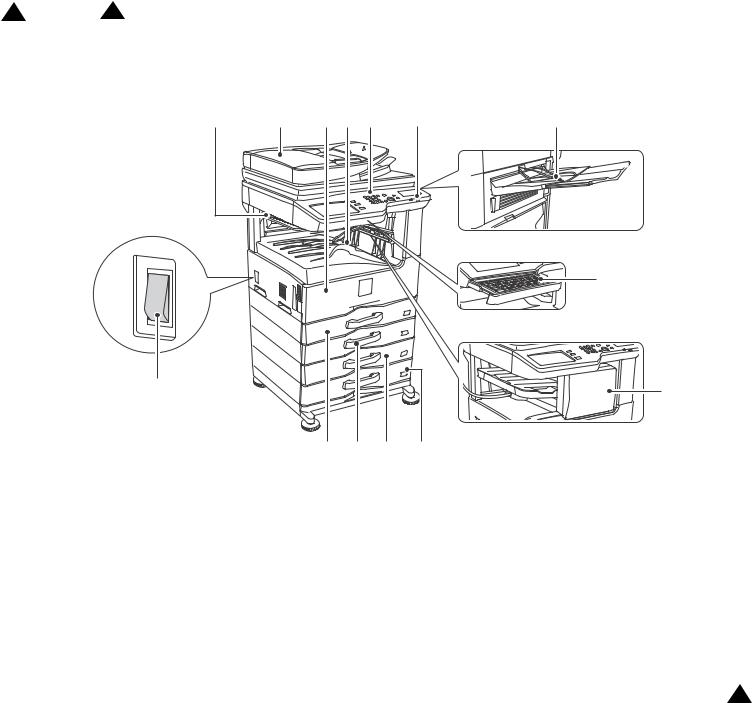
2 2013.8.23 |
3 ‘13/Oct |
[4] EXTERNAL VIEW AND INTERNAL STRUCTURE
1. External view
1 |
2 |
3 |
4 |
5 |
8 |
6 |
When a output tray unit is installed
9
When a keyboard is installed
10 |
7 |
|
|
|
When a finisher is installed |
|
|
11 |
12 |
13 |
14 |
|
|
|
|
|
|
|
|
No. |
Name |
|
|
|
Function/Operation |
|
1 |
Job separator tray (Upper tray) (optional) |
Print jobs and received faxes are delivered to this tray. |
|
|||
2 |
Automatic document feeder |
This automatically feeds and scans multiple originals. Both sides of 2-sided originals can be automatically |
|
|||
|
|
scanned. |
|
|
|
|
3 |
Front cover |
Open this cover to switch the main power switch to "On" or "Off" or to replace a toner cartridge. |
|
|||
4 |
Output tray (center tray) |
Output is delivered to this tray. |
|
|
||
5 |
Operation panel |
This is used to select functions and enter the number of copies. |
|
|||
6 |
Exit tray unit (right tray)*1 |
When installed, output can be delivered to this tray. |
|
|||
7 |
Finisher*1 |
This can be used to staple output. |
|
|
||
8 |
USB connector (A type) |
Supports USB 2.0 (Hi-Speed). |
|
|
||
|
|
This is used to connect a USB device such as USB memory to the machine. |
|
|||
|
|
For the USB cable, use a shielded cable. |
|
|||
9 |
Keyboard*1 |
The keyboard is integrated into the main unit. |
|
|||
|
|
If not using the keyboard, it can be retracted into the bottom of the operation panel. |
|
|||
10 |
Main power switch |
This is used to power on the machine. |
|
|||
|
|
When using the fax or Internet fax functions, keep this switch in the "on" position. |
|
|||
11 |
Tray 1 |
This holds paper. |
|
|
|
2 |
12 |
Tray 2 |
This holds paper. (Only for NV models, this is the option.) |
||||
13 |
Tray 3 (when a paper drawer is installed)*1 |
This holds paper. |
|
|
|
|
14 |
Tray 4 (when a paper drawer is installed)*1 |
This holds paper. |
|
|
|
|
*1: Peripheral device.
MX-M264U EXTERNAL VIEW AND INTERNAL STRUCTURE 4 – 1

2. Internal structure
1 |
2 |
3 |
4 |
5 |
6 |
7 |
8 |
|
9 |
No. |
Name |
Function/Operation |
1 |
Toner cartridge |
This holds toner for printing. The toner cartridge must be replaced when indicated on the operation panel. |
2 |
Upper cover of machine |
Open this cover to remove jam paper when a paper jam occurs in the output of the job separator or the optional |
|
|
finisher. |
3 |
Fusing unit |
Heat is applied here to fuse the transferred image onto the paper. |
4 |
Right side cover |
Open this cover to remove a misfeed. |
5 |
Right side cover release lever |
To remove a paper misfeed, pull and hold this lever up to open the right side cover. |
6 |
Photoconductive drum |
This drum has a photoconductive coating on its surface. |
|
|
The images are formed on top of this photoconductive surface. |
|
|
(The photoconductive coating is green in color.) |
7 |
Right cover of paper drawer (when a |
Open this to remove a paper misfeed in tray 3 or tray 4. |
|
paper drawer is installed) |
|
8 |
Paper tray right side cover |
Open this to remove a paper misfeed in tray 2. |
9 |
Bypass tray |
Use this tray to feed paper manually. |
|
|
When loading a large sheet of paper, be sure to pull out the bypass tray extension. |
MX-M264U EXTERNAL VIEW AND INTERNAL STRUCTURE 4 – 2

3. Automatic document feeder and document glass
1 |
2 |
3 |
4 |
5 |
6 |
7 |
|
|
8 |
|
|
|
No. |
Name |
Function/Operation |
1 |
Paper feed roller |
This roller rotates to automatically feed the original. |
2 |
Document feeding area cover |
Open this cover to remove an original misfeed or clean the paper feed roller. |
3 |
Original guides |
These help ensure that the original is scanned correctly. |
|
|
Adjust the guides to the width of the original. |
4 |
Document feeder tray |
Place originals in this tray. 1-sided originals must be placed face up. |
5 |
Original exit tray |
Originals are delivered to this tray after scanning. |
6 |
Scanning area |
Originals placed in the document feeder tray are scanned here. |
7 |
Original size detector |
This detects the size of an original placed on the document glass. |
8 |
Document glass |
Use this to scan a book or other thick original that cannot be fed through the automatic document feeder. |
MX-M264U EXTERNAL VIEW AND INTERNAL STRUCTURE 4 – 3
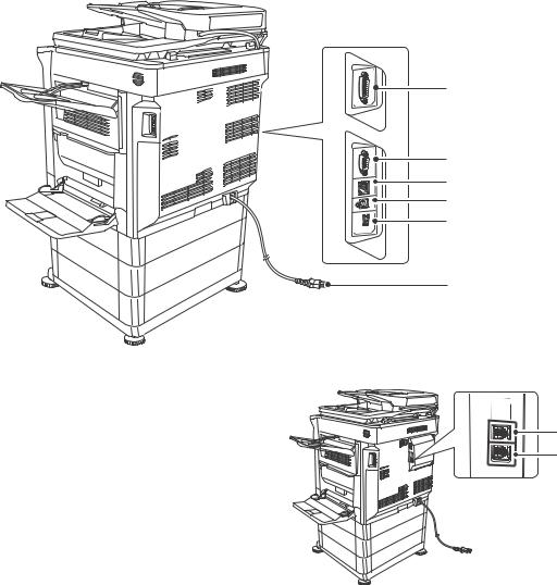
4. I/F connectors
1
2
3
4
5
6
When a fax expansion kit is installed
7
8
No. |
Name |
Function/Operation |
1 |
Connector for the finisher only |
Connects the finisher. |
2 |
Service-only connector |
This connector is for use only by service technicians. |
|
|
Connecting a cable to this connector may cause the machine to malfunction. |
|
|
Important note for service technicians: |
|
|
The cable connected to the service connector must be less than 118" (3 m) in length. |
3 |
LAN connector |
Connect the LAN cable to this connector when the machine is used on a network. |
|
|
For the LAN cable, use a shielded type cable. |
4 |
USB connector (B type) |
Supports USB 2.0 (Hi-Speed). |
|
|
A computer can be connected to this connector to use the machine as a printer. |
|
|
For the USB cable, use a shielded cable. |
5 |
USB connector (A type) |
Supports USB 2.0 (Hi-Speed). |
|
|
This is used to connect a USB device such as USB memory to the machine. |
6 |
Power plug |
|
7 |
Extension phone jack |
When the fax function of the machine is used, an extension phone can be connected to this jack. |
8 |
Telephone line jack |
When the fax function of the machine is used, the telephone line is connected to this jack. |
MX-M264U EXTERNAL VIEW AND INTERNAL STRUCTURE 4 – 4
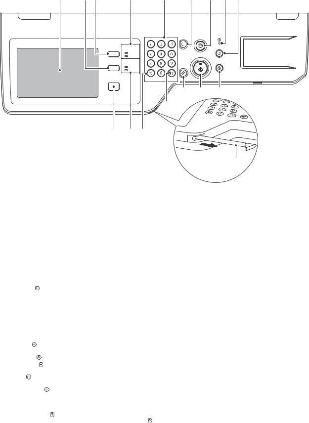
5. Operation panel
1 |
2 |
3 |
4 |
5 |
6 |
10 |
11 |
12 |
|
|
JOB STATUS |
|
|
|
|
|
|
|
|
|
READY |
|
|
|
|
|
|
|
|
DATA |
|
|
|
|
|
|
|
SYSTEM |
|
|
|
|
|
|
|
|
SETTINGS |
IMAGE SEND |
|
|
|
|
|
|
|
|
LINE |
|
|
|
|
|
|
|
|
DATA |
|
|
|
|
|
|
|
HOME |
|
LOGOUT |
|
|
|
|
|
|
|
|
|
|
|
|
15 16 17
14
7 8 13
9
No. |
|
Name |
|
|
Function/Operation |
1 |
Touch panel |
|
Messages and keys appear in the touch panel display. |
||
|
|
|
Touch the displayed keys to perform a variety of operations. |
||
|
|
|
When a key is touched, a beep sounds and the selected item is highlighted. This provides confirmation as you |
||
|
|
|
perform an operation. |
||
2 |
[SYSTEM SETTINGS] key |
Press this key to display the system settings menu screen. The system settings are used to configure paper |
|||
|
|
|
tray settings, store addresses for transmission operations, and adjust parameters to make the machine easier |
||
|
|
|
to use. |
||
3 |
[JOB STATUS] key |
Press this key to display the job status screen. The job status screen is used to check information on jobs and |
|||
|
|
|
to cancel jobs. |
||
|
|
|
For details, see the chapters for each of the functions in this manual. |
||
4 |
PRINT mode indicators |
• READY indicator: Print jobs can be received when this indicator is lit. |
|||
|
|
|
• DATA indicator: This blinks while print data is being received and lights steadily while printing is taking place. |
||
5 |
Numeric keys |
|
These are used to enter the number of copies, fax numbers, and other numerical values. These keys are also |
||
|
|
|
used to enter numeric value settings (except for the system settings). |
||
6 |
[CLEAR] key ( |
) |
Press this key to return the number of copies to "0". |
||
7 |
[HOME] key |
|
Touch this key to display the home screen. Frequently used settings can be registered in the home screen to |
||
|
|
|
enable quick and easy operation of the machine. |
||
8 |
IMAGE SEND mode indicators |
• LINE indicator: This lights up during transmission or reception of a fax or Internet fax. This also lights during |
|||
|
|
|
transmission of an image in scan mode. |
||
|
|
|
• DATA indicator: This blinks when a received fax or Internet fax cannot be printed because of a problem such |
||
|
|
|
as out of paper. |
||
|
|
|
This lights up when there is a transmission job that has not been sent. |
||
9 |
Stylus pen |
|
This can be used to touch a key displayed on the touch panel. |
||
10 |
[STOP] key ( ) |
|
Press this key to stop a copy job or scanning of an original. |
||
11 |
Main power indicator |
This lights up when the machine's main power switch is in the "on" position. |
|||
12 |
[POWER] key ( |
) |
Use this key to turn the machine power on and off. |
||
13 |
[LOGOUT] key ( |
) |
Press this key to log out after you have logged in and used the machine. When using the fax function, this key |
||
|
|
|
can also be pressed to send tone signals on a pulse dial line. |
||
14 |
[#/P] key ( ) |
|
When using the copy function, press this key to use a job program. When using the fax function, this key can be |
||
|
|
|
used when dialing. |
||
15 |
[CLEAR ALL] key ( ) |
Press this key to return to the initial operation state. |
|||
|
|
|
Use this key when you wish to cancel all settings that have been selected and start operation from the initial |
||
|
|
|
state. |
||
16 |
[START] key |
|
Press this key to copy or scan an original. This key is also used to send a fax in fax mode. |
||
17 |
[POWER SAVE] key ( ) / indicator |
Use this key to put the machine into auto power shut-off mode to save energy. |
|||
|
|
|
The [POWER SAVE] key ( |
|
) blinks when the machine is in auto power shut-off mode. |
MX-M264U EXTERNAL VIEW AND INTERNAL STRUCTURE 4 – 5

6. RSPF
A. Sensors and detectors
|
SCOV |
SPED |
|
|
|
SPPD1 |
SPLS2 |
|
|
|
SPPD2 |
|
SPLS1 |
|
|
SOCD |
SPWS |
|
|
|
|
|
|
|
|
SPPD3 |
SPPD4 |
|
|
Signal name |
Name |
Type |
Function/Operation |
Note |
SCOV |
RSPF cover open/close detector |
Micro switch |
Detects open/close of the RSPF cover. |
|
SOCD |
RSPF open/close sensor |
Transmission type |
Detects open/close of the RSPF unit. |
|
SPED |
Document sensor |
Transmission type |
Detects document empty in the RSPF paper feed tray. |
|
SPLS1 |
Paper size detector 1 |
Transmission type |
Detects the document length in the RSPF paper feed tray. |
|
SPLS2 |
Paper size detector 2 |
Transmission type |
Detects the document length in the RSPF paper feed tray. |
|
SPPD1 |
Document transport sensor 1 |
Transmission type |
Detects paper feed and the document size in random |
|
|
|
|
paper feed. |
|
SPPD2 |
Document transport sensor 2 |
Transmission type |
Detects paper pass. |
|
SPPD3 |
Document transport sensor 3 |
Transmission type |
Detects paper pass. |
|
SPPD4 |
Document transport sensor 4 |
Transmission type |
Detects paper exit and switchback. |
|
SPWS |
Document size detector |
Volume-type resistor |
Detects the document width. |
|
B. Motors, clutches, solenoids and PWB
SRRC |
SPFM |
STMPS |
|
 SPRS
SPRS


SPM (SPUM)
1
Signal name |
Name |
Type |
Function/Operation |
SPFM |
RSPF transport motor |
Stepping motor |
Transports a document. |
SPM/SPUM |
RSPF paper feed motor |
Stepping motor |
Feeds a document. |
SPRS |
Paper exit roller pressure control solenoid |
Magnetic solenoid |
Controls ON/OFF of the transport power of the paper exit roller. (Releases the |
|
(RSPF) |
|
paper exit roller pressure when reversing paper.) |
SRRC |
Registration roller clutch (RSPF) |
Magnetic clutch |
Controls the registration roller. (Controls the timing of document transport.) |
STMPS |
Stamp solenoid |
Magnetic solenoid |
Drives the finish stamp. |
No. |
Name |
Function/Operation |
1 |
RSPF driver PWB |
Drives the motor, the solenoid, and the clutch in the RSPF section. |
MX-M264U EXTERNAL VIEW AND INTERNAL STRUCTURE 4 – 6
Loading...