


 Loading...
SERVICE MANUAL
CODE: 00ZMXLCX1/S1E
DIGITAL FULL COLOR
MULTIFUNCTIONAL SYSTEM OPTION
LARGE CAPACITY TRAY
MODEL MX-LCX1
CONTENTS
[1] PRODUCT OVERVIEW. . . . . . . . . . . . . . . . . . . . . . . . . . . . . . . . . . 1-1
[2] SPECIFICATIONS . . . . . . . . . . . . . . . . . . . . . . . . . . . . . . . . . . . . . . 2-1
[3]UNPACKING AND INSTALLATION
*For how to unpacking and installation, refer to the installation manual (00ZMX2700/I1E).
[4] OUTSIDE VIEW AND INTERNAL STRUCTURE . . . . . . . . . . . . . . 4-1 [5] OPERATIONAL DESCRIPTIONS . . . . . . . . . . . . . . . . . . . . . . . . . . 5-1
[6] DISASSEMBLY AND ASSEMBLY. . . . . . . . . . . . . . . . . . . . . . . . . . 6-1
[7] MAINTENANCE. . . . . . . . . . . . . . . . . . . . . . . . . . . . . . . . . . . . . . . . 7-1 [8] ADJUSTMENT. . . . . . . . . . . . . . . . . . . . . . . . . . . . . . . . . . . . . . . . . 8-1 [9] SELF-DIAGNOSIS AND TROUBLE CODES . . . . . . . . . . . . . . . . . 9-1
[10] ELECTRICAL SECTION . . . . . . . . . . . . . . . . . . . . . . . . . . . . . . . . 10-1
[11] OTHER . . . . . . . . . . . . . . . . . . . . . . . . . . . . . . . . . . . . . . . . . . . . . 11-1
PARTS GUIDE
Parts marked with "  " are important for maintaining the safety of the set. Be sure to replace these parts with specified ones for maintaining the safety and performance of the set.
This document has been published to be used SHARP CORPORATION for after sales service only.
The contents are subject to change without notice.
CONTENTS
[1] PRODUCT OVERVIEW . . . . . . . . . . . . . . . . .1-1
[2] SPECIFICATIONS . . . . . . . . . . . . . . . . . . . . .2-1
[3]UNPACKING AND INSTALLATION
*For how to unpacking and installation, refer to the installation manual (00ZMX2700/I1E).
[4]OUTSIDE VIEW AND INTERNAL STRUCTURE
1. Part Names and Functions . . . . . . . . . . .4-1
[5] OPERATIONAL DESCRIPTIONS
1. Lift Operation . . . . . . . . . . . . . . . . . . . . . .5-1
2. Paper Feed Operation . . . . . . . . . . . . . . .5-1
3. Paper-on-tray Detection. . . . . . . . . . . . . .5-2
[6] DISASSEMBLY AND ASSEMBLY
1.Maintenance Parts Replacement
Procedures . . . . . . . . . . . . . . . . . . . . . . .6-1
2. Removal of Each Unit . . . . . . . . . . . . . . .6-1
3. Removal of Major Parts . . . . . . . . . . . . . .6-2
[7] MAINTENANCE
1. Maintenance Table. . . . . . . . . . . . . . . . . .7-1
[8] ADJUSTMENT
1. Adjustment Item List. . . . . . . . . . . . . . . . 8-1
2. Detailed Procedures. . . . . . . . . . . . . . . . 8-1
[9] SELF-DIAGNOSIS AND TROUBLE CODES
1. Simulations. . . . . . . . . . . . . . . . . . . . . . . 9-1
2. Self-diagnosis. . . . . . . . . . . . . . . . . . . . . 9-2
3. Trouble Code List . . . . . . . . . . . . . . . . . . 9-3
4. Trouble Code Details . . . . . . . . . . . . . . . 9-3
[10] ELECTRICAL SECTION
1.Electronic/Mechanical Parts
Relationship Diagram . . . . . . . . . . . . . . 10-1
2. Block Diagram . . . . . . . . . . . . . . . . . . . 10-2
3. Wiring Diagram. . . . . . . . . . . . . . . . . . . 10-3
[11]OTHER
1. Note for installation of the heater in a
certain destination . . . . . . . . . . . . . . . . 11-1
PARTS GUIDE

[1] PRODUCT OVERVIEW
This model is an externally mounted 3500-sheet paper feeder (large capacity paper feed tray) designed to attach to and work with compatible digital full-color copier products.
It can feed up to 3500 sheets of paper (80 g/m2, 21 lbs), thus allowing the user to handle large copy jobs without having to refill paper frequently.
The paper feeder has an additional separator mechanism that ensures long-term reliable paper feed.
Staple cartridge
(Approx. 5000 x 3) Finisher (MX-SCX1)
(MX-FNX1)
Punch module
●2-hole (MX-PNX1A)
●3-hole (MX-PNX1B)
●4-hole (MX-PNX1C)
●4-hole (broad space) (MX-PNX1D)
Paper pass unit (MX-RBX1)
Staple cartridge (Approx. 5000 x 3) (AR-SC2)
Device Tray with |
|
|
USB Hub (MX-RKX1) |
Reversing single pass feeder |
|
|
|
(MX-RPX1) |
PCL5c/PCL6 |
Network |
SPLC-c |
driver |
scanner |
driver |
|
(Sharpdesk 1 license) |
|
|
|
Document cover |
RSPF |
|
(MX-VRX1) |
HDD |
HDD |
Exit tray unit |
|
||
|
|
(MX-TRX1) |
Copier/Printer (PCL) |
Copier/Printer (SPLC-c) |
|
/Scanner model |
model |
|
(MX-2300N) (MX-2300G) (MX-2700N) (MX-2700G)
Punch module |
|
|
|
|
|
● 2-hole (AR-PN1A) |
|
|
|
|
|
● 3-hole (AR-PN1B) |
|
|
|
|
|
● 4-hole (AR-PN1C) |
Saddle stitch finisher |
Stand/1x500 sheet |
Stand/2x500 sheet |
Large capacity tray |
|
● 4-hole (broad space) |
(MX-FNX2) |
paper drawer |
paper drawer |
(MX-LCX1) |
|
(AR-PN1D) |
|
(MX-DEX1) |
|
(MX-DEX2) |
|
|
Barcode font kit |
Printer expansion |
Network scanner |
PS3 expansion |
Facsimile |
|
|
kit (PCL) |
expansion kit |
kit |
|
|
|
expansion kit |
|||
|
|
|
|
|
|
|
|
|
|
|
(MX-FXX1) |
|
CD |
ROM |
|
|
CD |
ROM |
|
|
|
|
|
|
|
||
|
(AR-PF1) |
CD |
CD |
|
|
|
|
|
(MX-PBX1) |
(MX-NSX1) |
|
|
FAX memory (8MB) |
||
|
|
|
|
|
|||
Data security kit |
|
(For MX-2300G/2700G) |
(MX-PKX1) |
(packed together) |
|||
|
|
||||||
(Including document control) |
|
|
|
|
|
|
|
CC authentication |
Commercial |
|
Internet Fax |
Sharpdesk |
Sharpdesk |
|
|
|
expansion kit |
1 license kit |
10 license kit |
|
|||
version |
version |
|
|
||||
|
|
|
|
|
|
||
|
|
|
|
Sharpdesk |
Sharpdesk |
|
|
|
|
|
|
5 license kit |
50 license kit |
|
|
Security |
Security |
|
|
|
|
|
|
ROM |
ROM |
|
|
|
|
|
|
|
|
|
CD |
CD |
|
CD |
|
|
|
|
|
(MX-USX1/ |
(MX-US10/ |
|
|
|
|
|
(MX-FWX1) |
USX5) |
|
US50) |
|
For document |
For document |
Application |
Sharpdesk |
Application |
External |
||
control PWB |
control PWB |
||||||
(MX-FRX1) |
(MX-FRX1U) |
integration |
100 license kit |
communication |
account module |
||
module |
|
module |
|
||||
|
|
|
|
|
|||
256MB expansion memory board |
|
|
|
|
(MX-SMX1) |
|
|
|
|
|
CD |
CD |
CD |
CD |
(For MX-2300G/2700G) |
(MX-AMX1) |
(MX-USA0) |
(MX-AMX2) |
(MX-AMX3) |
MX-LCX1 PRODUCT OVERVIEW 1 – 1
[2] SPECIFICATIONS
Type |
Externally mounted 3500-sheet paper feeder |
Transport speed |
Operable within the speed range of 124 to 360 mm/s (Speed can be selected using a communication command). |
Transport reference |
Center reference |
Paper size |
AB series: A4, 8.5" x 11" |
|
AB, B5 series: A4, B5, 8.5" x 11” |
|
Inch series: 8.5" x 11", A4 |
Paper size setting |
Service engineer support/simulation setup |
Factory default paper size setting |
AB series: A4 |
|
Inch series: 8.5" x 11" |
Paper type setting |
Provided |
Supported paper types/weight |
Plain paper, printed paper, recycled paper, letter head, pre-punched paper, color paper: 60 to 105 g/m2 (16 to 28 lbs) |
Paper capacity |
3500 sheets (80 g/m2 (21 lbs)), at effective height of 385 mm |
Paper level detection |
The paper feeder detects the amount of remaining paper and indicates one of seven levels (100%, 83.3%, 66.7%, 50.0%, |
|
33.3%, 16.7%, and none) on its own panel or on the printer's display. |
Paper refill method |
Front loading type; paper can be refilled from the upper part. |
Drive mechanism |
Transport motor (brushless DC motor) controlled by a controller board built in the LCC |
Jam processing |
Can be done by moving the unit to the right or drawing out the tray. |
Off-center adjustment |
±3 mm (can be adjusted by moving the front and rear regulation plates). |
Vertical tray movement time |
Up: within 15 seconds (with no paper loaded; from tray insertion to "empty" detection). |
|
Down: within 5 seconds |
Power consumption |
Max. 26.4W |
(except for the heater) |
Lift-up: Max. 40.8W |
Power supply |
5V ± 5% and 24V ± 5% (Supplied from the main unit) |
Outside dimensions (W x D x H) |
370 x 550 x 520 (mm), 14 9/16 x 21 21/32 x 20 15/32 (inch) |
Occupying area (W x D) |
370 x 550 (mm) (Clearance from the main unit: 235 mm), 14 9/16 x 21 21/32 (inch) (Clearance from the main unit: 9 1/4 inch) |
Weight |
Approx. 30 kg (66.1 lbs) |
Paper feed system |
Paper pick-up with the aid of a take-up roller; torque limiter reverse rotation separation system |
Heater |
Service parts (kit): When installing, refer to [11]. |
Installation/maintenance |
Installed by service personnel |
Optional detection |
Auto detection supported |
Packaged items |
Parts for mounting, installation cautionary note |
MX-LCX1 SPECIFICATIONS 2 – 1
[4] OUTSIDE VIEW AND INTERNAL STRUCTURE
1. Part Names and Functions
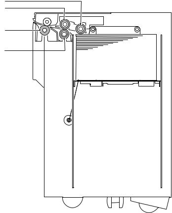
A. Internal Structure
1
2
3 |
4
No. |
Name |
1 |
Pick-up roller |
2 |
Paper feed roller |
3 |
Transport roller |
4 |
Reverse roller |
MX-LCX1 OUTSIDE VIEW AND INTERNAL STRUCTURE 4 – 1
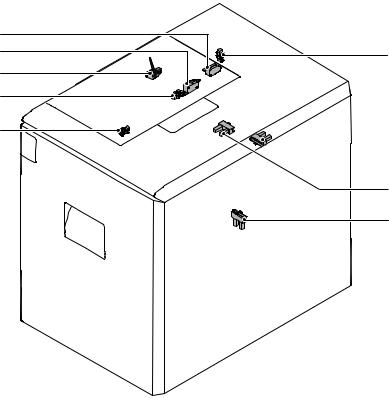
B. Sensors and Switches
9 |
|
8 |
4 |
5 |
|
6 |
|
7
 2
2
3
1
No. |
Signal |
Name |
Type |
Function/operation |
Activation condition |
1 |
LDD |
Tray lower limit sensor |
Transmission |
This sensor detects when the tray has |
The signal becomes High level when the tray is |
|
|
|
type |
reached its lower limit. |
at its lower limit. |
2 |
LRE |
Lift motor encoder sensor |
Transmission |
This sensor detects when the lift motor |
Pulse signal. |
|
|
|
type |
rotates. |
|
3 |
LCD |
Tray insertion sensor |
Transmission |
This sensor detects when the tray is |
The signal becomes High level when the tray is |
|
|
|
type |
inserted. |
inserted. |
4 |
LTOD |
Main unit connection sensor |
Transmission |
This sensor detects when the paper feeder is |
The signal becomes Low level when connected |
|
|
|
type |
connected to the main unit. |
to the main unit. |
5 |
LPFD |
Transport sensor |
Transmission |
This sensor detects when paper is |
The signal becomes Low level when paper is |
|
|
|
type |
transported. |
transported (when paper exists). |
6 |
LUD |
Tray upper limit sensor |
Transmission |
This sensor detects when the tray has |
The signal becomes High level when the tray is |
|
|
|
type |
reached its upper limit. |
at its upper limit (with the lift-up motor stopped). |
7 |
LPED |
Paper-on-tray sensor |
Transmission |
This sensor detects whether there is paper in |
The signal becomes Low level when paper is in |
|
|
|
type |
the tray. |
the tray. |
|
|
|
|
|
* When the tray is being lifted up and this |
|
|
|
|
|
signal is at Low level with the LRE signal not |
|
|
|
|
|
exceeding 800 pulses, the paper feed |
|
|
|
|
|
solenoid turns ON. |
8 |
LLSW |
Upper limit switch |
Microswitch |
This limit switch is intended to prevent the |
– |
|
|
|
|
tray from overrunning the upper limit and |
|
|
|
|
|
breaking the paper feed unit. |
|
9 |
LDSW |
Upper door latch switch |
Microswitch |
This switch detects when the upper door is |
– |
|
|
|
|
opened or closed. |
|
MX-LCX1 OUTSIDE VIEW AND INTERNAL STRUCTURE 4 – 2
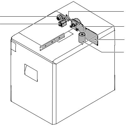
C. Drive and Control Components
4
3 |
|
5 |
1 |
|
6
7 
2
No. |
Signal |
Name |
Type |
Function/operation |
Activation condition |
1 |
LPFM |
LCC transport motor |
– |
This motor drives the paper feed |
The signal becomes High level when paper feed is |
|
|
|
|
and transport sections. |
started. |
2 |
LLM |
LCC lift motor |
Brush motor |
This motor raises the paper feed |
The signal is High level when the motor is working; |
|
|
|
|
table. |
when the upper limit sensor turns ON, the motor |
|
|
|
|
|
stops and the signal becomes Low level. |
3 |
LTRC |
LCC transport |
Electromagnetic |
This clutch controls the ON/OFF |
– |
|
|
clutch |
clutch |
status of the transport roller. |
|
4 |
LPFC |
LCC paper feed |
Electromagnetic |
This clutch controls the ON/OFF |
The signal becomes High level when paper feed is |
|
|
clutch |
clutch |
status of the paper feed roller. |
started; |
|
|
|
|
|
the clutch is turned OFF by a timer after transport |
|
|
|
|
|
is started (with the pick roller turned OFF). |
5 |
LPFS |
LCC paper feed |
Electromagnetic |
This solenoid presses the paper |
The solenoid is turned OFF after transport is |
|
|
solenoid |
solenoid |
pick-up roller onto the paper. |
started and, when the time is up, it is turned ON |
|
|
|
|
|
again. |
|
|
|
|
|
The solenoid is ON between lift-up and the |
|
|
|
|
|
activation of the Paper-on-tray sensor. |
6 |
LCC MAIN PWB CR |
LCC main board CR |
– |
Controls and drives LCC. |
– |
7 |
DH (Service parts (kit): |
LCC heater |
– |
This heater is used to keep |
– |
|
When installing, refer |
|
|
warm the LCC tray interior. |
|
|
to [11].) |
|
|
|
|
MX-LCX1 OUTSIDE VIEW AND INTERNAL STRUCTURE 4 – 3

[5] OPERATIONAL DESCRIPTIONS
1. Lift Operation
When the power to the main unit is turned ON with the tray at a midway position (that is, a position where both the upper limit sensor [LUD] and lower limit sensor [LDD] are OFF) or with the tray at the lower limit position (where the lower limit sensor LDD is ON), the main unit issues a lift-up request and, in response, the lift motor is turned ON to lift the tray.
If the Paper-on-tray sensor (LPED) turns ON within 800 encoder pulses of the start of tray lift, the lift motor is temporarily turned OFF to stop the tray, and then the paper feed solenoid is turned ON to lower the pick roller. Subsequently, the lift motor is turned ON, and the tray is lifted to and stopped at a position where the upper limit sensor (LUD) is turned ON.
If the Paper-on-tray sensor (LPED) does NOT turn ON within 800 pulses of the start of tray lift, the paper feed solenoid is turned ON with the lift motor remaining ON, and the pick roller is lowered. The lift motor stops when the tray reaches a position where the upper limit sensor (LUD) is turned ON, and subsequently the paper feed solenoid is turned OFF.
Lift operation is not performed if the power to the main unit is turned ON with the tray at a position where it can feed paper.
When the tray is drawn out, it lowers by its own weight.
2. Paper Feed Operation
Lift operation (where LPED turns ON within 800 encoder pulses of the start of lift operation)
200 msec
LLM  (lift motor output)
LDD (lower limit sensor)
LUD (upper limit sensor)
LPED (paper-on-tray sensor)
LPFS |
|
(solenoid) |
Within 800 pulses |
LRE  (encoder signal)
Lift operation (where LPED does NOT turn ON within 800 encoder pulses of the start of lift operation)
LLM (lift motor output)
LDD (lower limit sensor)
LUD (upper limit sensor)
LPED (paper-on-tray sensor)
LPFS
(solenoid)
800
LRE (encoder signal)
Paper feed operation can be performed if the tray is stationary at a position where it can feed paper (with the upper limit sensor [LUD] being ON) and there is paper in the tray.
When paper feed takes place, the transport motor (LPFM), the transport clutch (LTRC), the paper feed clutch (LPFC), and the paper feed solenoid (LPFS) operate with the following timings:
Paper feed time chart (with acceleration)
When the transport clutch (LTRC) turns ON with the transport motor (LPFM) is ON (rotating), the transport roller starts rotating. When the paper feed clutch (LPFC) turns ON in this state, the paper feed and take-up rollers start rotating.
When the paper feed solenoid (LPFS) turns ON, the take-up roller is pushed down to press paper.
|
|
|
Start of job |
|
Catch-up control |
Catch-up control |
|||||||||
Accelerating speed |
|
|
|
|
|
|
|
|
|
|
|
|
|||
LPFM |
Process speed |
|
|
|
|
|
|
|
|
|
|
|
|
||
|
|
|
|
|
|
|
|
|
|
|
|
||||
|
|
|
|
|
|
|
|
|
|
|
|
|
|
|
|
(transport |
suspended |
Clearance-between-papers |
|
|
|
Clearance-between-papers |
|
|
|
|
|||||
motor) |
|
|
|
|
|
|
|
|
|
|
|||||
|
|
|
control timer |
|
|
|
control timer |
|
|
|
|
||||
|
|
|
|
|
|
|
|
|
|
|
|||||
LPFD |
|
on |
|
|
|
|
|
|
|
|
|
|
|
|
|
(transport |
|
off |
|
|
|
|
|
|
|
|
|
|
|
|
|
sensor) |
|
|
|
|
|
|
|
|
|
|
|
|
|
|
|
|
|
|
|
PIC timer |
|
|
|
PIC timer |
|
|
|
|
|||
LPFS |
|
on |
|
|
|
|
|
|
|
|
|
|
|
|
|
(paper feed |
|
off |
|
|
|
|
|
|
|
|
|
|
|
|
|
solenoid) |
|
Paper feed clutch |
|
|
Paper feed clutch |
|
|
|
|
||||||
|
|
|
|
|
|
|
|
|
|||||||
|
|
|
|
OFF timer |
|
|
OFF timer |
|
|
|
|
||||
LPFC |
|
on |
|
|
|
|
|
|
|
|
|
|
|
|
|
|
|
|
|
|
|
|
|
|
|
|
|
|
|||
(paper feed |
|
off |
|
|
|
|
|
|
|
|
|
|
|
|
|
clutch) |
|
|
|
|
|
|
|
|
|
|
|
|
|
||
|
|
|
|
|
|
|
|
|
|
|
|
|
|
|
|
LTRC |
|
on |
|
|
|
|
|
|
|
|
|
|
|
|
|
|
|
|
|
|
|
|
|
|
|
|
|
|
|||
(transport |
|
off |
Start of 1st |
Start of 2nd |
Start of 3rd |
||||||||||
clutch) |
|
||||||||||||||
|
|
|
paper feed |
paper feed |
paper feed |
||||||||||
|
|
|
|
||||||||||||
TRC |
|
on |
|
|
|
|
|
|
|
|
|
|
|
|
|
(main unit |
|
|
|
|
|
|
|
|
|
|
|
|
|
|
|
|
off |
|
|
|
|
|
|
|
|
|
|
|
|
||
synchronization |
|
|
|
|
|
|
|
|
|
|
|
|
|||
signal) |
*1 |
|
*1:
Operation stops only if the main unit synchronization signal is output.
When operation is stopped, the ON/OFF timing for each load is delayed by the stoppage time because each timer is suspended during the stoppage.
To ensure efficient job processing, operation is not stopped under normal conditions.
MX-LCX1 OPERATIONAL DESCRIPTIONS 5 – 1

5 |
1 |
|
4 |
||
|
6
3
7
2
1 |
LCC Paper feed roller clutch |
2 |
Take-up roller |
3 |
Paper feed roller |
4 |
LCC Paper feed solenoid |
5 |
LCC Transport clutch |
6 |
LCC Transport motor |
7 |
LCC Lift-up motor |
3. Paper-on-tray Detection
The Paper-on-tray sensor (LPED) checks whether there is paper in the tray when the tray is lifted and stopped at a position where it can feed paper, as well as during paper feed operation.
Paper feed operation is stopped if the sensor detects no paper in the tray during paper feed operation.
MX-LCX1 OPERATIONAL DESCRIPTIONS 5 – 2
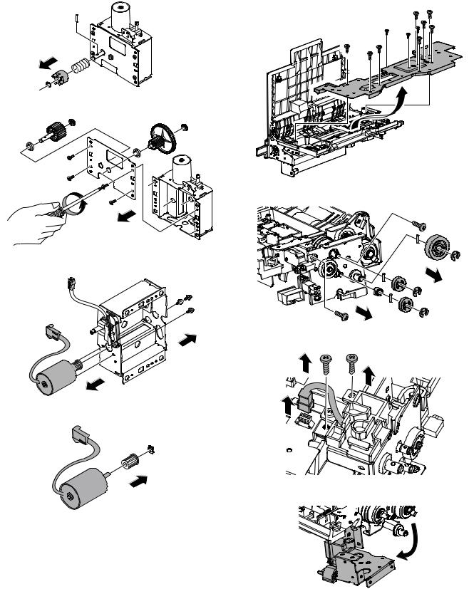
[6] |
DISASSEMBLY AND |
2. Removal of Each Unit |
|
ASSEMBLY |
A. Paper feed unit |
|
|
1) Draw out the tray. |
1. |
Maintenance Parts Replacement |
|
|
Procedures |
|
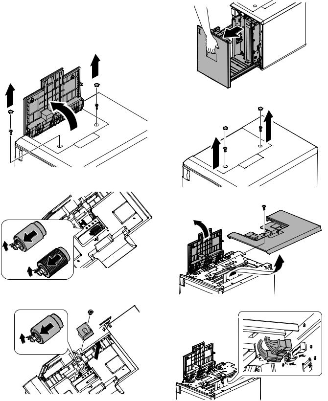
A.Paper feed roller, pick-up roller, and reverse roller
1)Remove the screw caps and then remove the screws.
Open the upper cover.
2) Remove the screw caps and then remove the screws.
2)Remove the pick-up and paper feed rollers after releasing their pawls.
3) Open the upper cover, and remove the upper cabinet.
3)Remove the screw and remove the paper guide block.
4)Remove the reverse roller after releasing its pawl.
4) Disconnect the connectors.
MX-LCX1 DISASSEMBLY AND ASSEMBLY 6 – 1
5) Remove the screws and remove the paper feed unit. |
C. Drive unit |
|
1) Remove the screws and remove the rear cover. |
2) Disconnect the connectors.
B. Paper tray
1) Draw out the tray.
2)Looser the stopper fixing screw (1) on the lower right side of the paper tray, evacuate the stopper not to function.
3) Remove the screws and remove the drive unit.
3) Remove the screws from the left and right rails.
3. Removal of Major Parts
A. Transport motor
|
1) |
Remove the screws and remove the rear cover. |
|
4) Detach the tray unit from the rails. |
2) |
Disconnect the connectors. |
|
3) |
Remove the screws and remove the transport motor. |
||
|
MX-LCX1 DISASSEMBLY AND ASSEMBLY 6 – 2
B. Lift motor
1)Remove the drive unit.
2)Remove the E ring and remove each part.
3)Remove the screws and remove the cover.
4)Remove the screws and remove the lift motor.
5)Remove the ring and remove the pulley.
C. Paper feed clutch and transport clutch
1)Remove the paper feed unit. (See "2. Removal of Each Unit.")
2)Remove the screws and remove the cover.
3)Remove the E ring and remove each part.
4)Disconnect the connector and then remove the screws.
5)Remove the frame.
MX-LCX1 DISASSEMBLY AND ASSEMBLY 6 – 3

6)Disconnect the connectors. Remove the E ring and remove the paper feed clutch and transport clutch.
4)Lift the shaft, and remove the torque limiter.
D. Paper feed solenoid
1)Remove the paper feed unit.
2)Remove the cover.
3)Remove the screws and remove the solenoid unit. Disconnect the connectors.
4)Remove the screws and remove the solenoid.
E. Torque limiter
1)Remove the paper feed unit.
2)Remove the cover.
3)Remove the E ring and screws, and remove each part.
F. Transport roller
1)Remove the paper feed unit.
2)Remove the cover.
3)Remove the spring. Remove the screws.
4)Remove the plate cover. Remove the lever.
5)Remove the clutch.
6)Remove the screws and E ring, and remove each part.
7)Remove the transport roller.
MX-LCX1 DISASSEMBLY AND ASSEMBLY 6 – 4

[7] |
MAINTENANCE |
|
|
|
|
|
1. |
Maintenance Table |
|
|
|
|
|
: Check (clean, replace or adjust as required) {: Clean |
: Replace |
: Adjust : Lubricate |
: Relocate |
|||
|
|
|
|
|
|
|
No. |
Part name |
When |
|
Main unit |
|
Remarks |
calling |
maintenance cycle |
|
||||
|
|
|
|
|||
1 |
Pick-up roller/each paper feed roller |
|
|
{ |
As a rough guide, these rollers should be replaced when the LCC paper |
|
|
|
|
|
|
feed counter reaches a value of 100K (Sim22-9) or when one year has |
|
|
|
|
|
|
elapsed since the start of use. |
|
2 |
Torque limiter |
|
|
|
As a rough guide, the torque limiter should be replaced when the LCC |
|
|
|
|
|
|
paper feed counter reaches a value of 100K (Sim22-9). |
|
3 |
Each transport rollers |
|
|
{ |
|
|
4 |
Each transport paper guides |
{ |
|
{ |
|
|
5 |
Each gears |
|
|
|
|
|
6 |
Each belts |
|
|
|
|
|
7 |
Each sensors |
|
|
|
|
|
4
7 |
7 |
|
|
||
|
2 |
|
3 |
7 |
|
|
||
1 |
7 |
|
1 |
||
|
||
7 |
6 |
|
1 |
|
|
|
7 |
MX-LCX1 MAINTENANCE 7 – 1
Loading...