


MX-FNX2
Table of contents
 Loading...
SHARP MX-FNX2, ARPN1A, ARPN1B, ARPN1C, ARPN1D Service Manual
...
SERVICE MANUAL
CODE: 00ZMXFNX2/S1E
DIGITAL FULL COLOR
MULTIFUNCTIONAL SYSTEM OPTION
SADDLE STITCH FINISHER
PUNCH MODULE
PAPER PASS UNIT
MX-FNX2
AR-PN1A/B/C/D
MODEL
[1] PRODUCT OUTLINE . . . . . . . . . . . . . . . . . . . . . . . . . . . . . . . . . . . 1-1
[2] SPECIFICATIONS. . . . . . . . . . . . . . . . . . . . . . . . . . . . . . . . . . . . . . 2-1
[3] UNPACKING AND INSTALLATION
* For how to unpacking and installation, refer to the installation manual (00ZMX2700/I1E).
[4] EXTERNAL VIEWS AND INTERNAL STRUCTURES . . . . . . . . . . 4-1
[5] OPERATIONAL DESCRIPTION . . . . . . . . . . . . . . . . . . . . . . . . . . . 5-1
[6] DISASSEMBLY AND ASSEMBLY. . . . . . . . . . . . . . . . . . . . . . . . . . 6-1
[7] MAINTENANCE . . . . . . . . . . . . . . . . . . . . . . . . . . . . . . . . . . . . . . . 7-1
[8] ADJUSTMENTS . . . . . . . . . . . . . . . . . . . . . . . . . . . . . . . . . . . . . . . 8-1
[9] SELF DIAG MESSAGE AND TROUBLE CODE. . . . . . . . . . . . . . . 9-1
MX-RBX1
CONTENTS
[10] ELECTRICAL SECTION . . . . . . . . . . . . . . . . . . . . . . . . . . . . . . . . 10-1
PARTS GUIDE
Parts marked with " " are important for maintaining the safety of the set. Be sure to replace these parts with
specified ones for maintaining the safety and performance of the set.
This document has been published to be used
SHARP CORPORATION
for after sales service only.
The contents are subject to change without notice.

CONTENTS
[1] PRODUCT OUTLINE
1. Product outline. . . . . . . . . . . . . . . . . . . . .1-1
2. Configuration . . . . . . . . . . . . . . . . . . . . . .1-1
[2] SPECIFICATIONS
1. MX-FNX2 . . . . . . . . . . . . . . . . . . . . . . . . .2-1
2. AR-PN1A/B/C/D. . . . . . . . . . . . . . . . . . . .2-2
3. MX-RBX1. . . . . . . . . . . . . . . . . . . . . . . . .2-2
[3] UNPACKING AND INSTALLATION
* For how to unpacking and installation, refer to the
installation manual (00ZMX2700/I1E).
[4] EXTERNAL VIEWS AND INTERNAL
STRUCTURES
1. Part names and functions . . . . . . . . . . . .4-1
[5] OPERATIONAL DESCRIPTION
1. Basic operations . . . . . . . . . . . . . . . . . . .5-1
2. Feed/Drive System . . . . . . . . . . . . . . . . .5-4
3. Stapling Operation . . . . . . . . . . . . . . . . . .5-7
4. Delivery Tray Operation. . . . . . . . . . . . .5-10
5. Saddle Unit . . . . . . . . . . . . . . . . . . . . . .5-10
[6] DISASSEMBLY AND ASSEMBLY
1. Saddle stitch finiser (MX-FNX2) . . . . . . 6-1
2. Paper Transport Section (MX-RBX1) . . 6-11
3. Punch Unit (AR-PN1A/B/C/D) . . . . . . 6-14
[7] MAINTENANCE
1. Maintenance System Table . . . . . . . . . 7-1
[8] ADJUSTMENTS
1. Finisher/saddle unit . . . . . . . . . . . . . . . 8-1
2. Punch unit (option) . . . . . . . . . . . . . . . . 8-1
[9] SELF DIAG MESSAGE AND TROUBLE CODE
1. Self diag message . . . . . . . . . . . . . . . . 9-1
2. Trouble code . . . . . . . . . . . . . . . . . . . . 9-1
[10] ELECTRICAL SECTION
1. Block diagram. . . . . . . . . . . . . . . . . . . 10-1
2. Wiring diagram . . . . . . . . . . . . . . . . . . 10-3
3. LEDs and Check Pins by PCB . . . . . . 10-8
PARTS GUIDE
âºíuÇ´
[1] PRODUCT OUTLINE
Service Manual
1. Product outline
This unit is installed to the following machines to perform the after-process of output paper from a copier, or a fax machine. The output paper is
passed to the saddle finisher by the interface unit (MX-RBX1). Each sheet is discharged one by one by the offset function.
1) Employment of the through-type stapler: Employment of the through-type stapler allows to make saddle stitch by one stapler.
2) 3 kinds of auto staple functions:
There are 3 staple positions available. (One position in the front, one position at the back, 2 positions at the center)
3) Saddle stitch function: Up to 10 sheets of paper can be stapled at the center and folded into two and discharged.
4) Punch function (Option):
2
By installation of a puncher unit, paper can be punched to make holes for a binder. (Applicable for 64 – 128g/m
. OHP films cannot be
used.)
Applicable models MX-2300N/2700N/2300G/2700G
The finisher requires staple cartridge as a consumable part. (Staple cartridge (About 5000 staples x 3) AR-SC2)
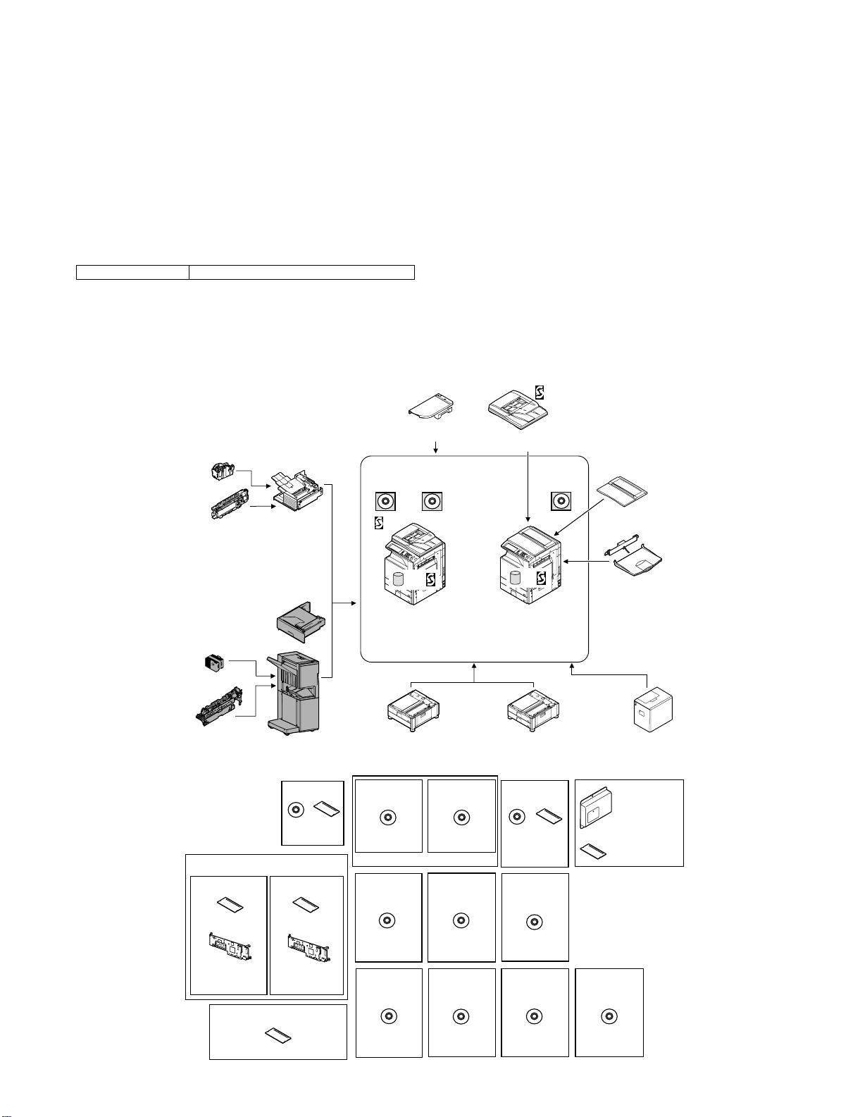
2. Configuration
1) When installing this unit, the paper feed desk (MX-DEX1/DEX2) and the interface unit (MX-RBX1) must be installed together.
2) This unit cannot be installed with the finisher (MX-FNX1) simultaneously.
Staple cartridge
(Approx. 5000 x 3)
(MX-SCX1)
Punch module
●
2-hole (MX-PNX1A)
●
3-hole (MX-PNX1B)
●
4-hole (MX-PNX1C)
●
4-hole (broad space)
(MX-PNX1D)
Staple cartridge
(Approx. 5000 x 3)
(AR-SC2)
Punch module
●
2-hole (AR-PN1A)
●
3-hole (AR-PN1B)
●
4-hole (AR-PN1C)
●
4-hole (broad space)
(AR-PN1D)
(Including document control)
CC authentication
version
Security
ROM
For document
control PWB
(MX-FRX1)
Finisher
(MX-FNX1)
Paper pass unit
(MX-RBX1)
Saddle stitch finisher
(MX-FNX2)
Barcode font kit
CD
ROM
(AR-PF1)
Data security kit
Commercial
version
Security
ROM
For document
control PWB
(MX-FRX1U)
256MB expansion memory board
(MX-SMX1)
(For MX-2300G/2700G)
Device Tray with
USB Hub (MX-RKX1)
PCL5c/PCL6
driver
RSPF
HDD
Copier/Printer (PCL)
/Scanner model
(MX-2300N)
(MX-2700N)
Stand/1x500 sheet
paper drawer
(MX-DEX1)
Printer expansion
kit (PCL)
CD
(MX-PBX1)
(For MX-2300G/2700G)
Internet Fax
expansion kit
CD
(MX-FWX1)
Application
integration
module
CD
(MX-AMX1)
Network
scanner
(Sharpdesk 1 license)
Network scanner
expansion kit
CD
(MX-NSX1)
Sharpdesk
1 license kit
Sharpdesk
5 license kit
CD
(MX-USX1/
USX5)
Sharpdesk
100 license kit
CD
(MX-USA0)
Reversing single pass feeder
(MX-RPX1)
SPLC-c
driver
HDD
Copier/Printer (SPLC-c)
model
(MX-2300G)
(MX-2700G)
Stand/2x500 sheet
paper drawer
(MX-DEX2)
PS3 expansion
kit
CD ROM
(MX-PKX1)
Sharpdesk
10 license kit
Sharpdesk
50 license kit
CD
(MX-US10/
US50)
Application
communication
module
CD
(MX-AMX2)
Document cover
(MX-VRX1)
Exit tray unit
(MX-TRX1)
Large capacity tray
(MX-LCX1)
Facsimile
expansion kit
(MX-FXX1)
FAX memory (8MB)
(packed together)
External
account module
CD
(MX-AMX3)
MX-FNX2/AR-PN1/MX-RBX1 PRODUCT OUTLINE 1 – 1

âºíuÇ´
[2] SPECIFICATIONS
Service Manual
1. MX-FNX2
A. Basic specifications
Type Console type finisher
Loading method Ascending offset tray
Transport speed 23/27/35/45 ppm
Transport reference Center reference
Mode types Non-staple, staple
Paper sizes allowed for offset A3, B4, A4, A4R, B5, B5R, 8K, 16K, 11" x 17", 8.5" x 14", 8.5" x 13", 8.5" x 11", 8.5" x 11"R
Offset quantity 20mm, 0.8 inch
Tray type (Number of trays) Upper tray: Lift-up/down offset tray
Paper exit direction Face down
Paper exit paper size A3W, A3, B4, A4, A4R, B5, B5R, A5R, 16K, 16KR
Power consumption 52W
Power source Supplied from the host machine power (DC24V/DC5V)
External dimensions (W x D x H) When the paper exit tray is on the storge position: 555 x 610 x 1010 (mm), 21 27/32 x 24 1/64 x 39 49/64 (inch)
Occupying dimensions (W x D) When the tray is on pull-out position: 665 x 610 (mm), 21 27/32 x 24 1/64 (inch)
Weight Approx. 46kg (101.4 lbs)
Installation/maintenance Installed by service personnel
Optional detection Auto detection supported
Packaged items Parts for mounting, operational sheet, staple directional instruction label, punch directional instrucrtion label,
B. Finishing section
Lower tray: Book tray for saddle stitch
12" x 18", 11" x 17", 8.5" x 14", 8.5" x 13", 8.5" x 11", 8.5" x 11"R, 5.5" x 8.5"R, 7.25" x 10.5"R
When the paper exit tray is on the pull-out position: 665 x 610 x 1050 (mm), 26 11/64 x 24 1/64 x 41 21/64 (inch)
* Distance from the main unit: 300mm, 11 13/16 inch
installation cautionary note
Capacity of paper exit and load Non-staple: 1,000 sheets (Small size) Max. 500 sheets for A5R, INV-R (Plain paper 60 to 80g/m
Staple sort: 30 sets * (Max. 50 sets for small size, one-position stapling at the rear)
Max: 1,000 sheets (Small size)
*: Less than 1,000 sheets and less than 30 sets depending on the use environment and paper curl.
Large size: A3W, A3, B4, 8K, 12" x 18", 11" x 17", 8.5" x 14", 8.5" x 13"
Small size: A4, A4R, B5, B5R, A5R, 16K, 16KR, 8.5" x 11", 8.5" x 11"R, 5.5" x 8.5"R, 7.25" x 10.5"R
Offset function Provided
Paper size which can be stapled A3, B4, A4, A4R, B5, B5R, 8K, 16K, 16KR, 11" x 17", 8.5" x 14", 8.5" x 13", 8.5" x 11", 8.5" x 11"R
Ejectable paper size Determinate
size
Indeterminate
size
Paper weight Thin paper:
Plain paper:
Heavy paper:
Quantity of paper to be stapled (Max.) 30 sheets (Small size, 90g/m
25 sheets (Large size, 90g/m
Stapling 3 kinds (One in the front, one at the back, two positions)
Staple supply Staple cartridge replacement
Staple detection Staple empty detection: Provided (Nearly empty: 40 pcs. remained)
Manual stapling No
or equivalent)
500 sheets (Large size) (Plain paper 60 to 80g/m
500 sheets (Large size)
AB type A3W, A3, B4, A4, A4R, B5, B5R, A5R, 8K, 16K, 16KR
Inch type 12" x 18", 11" x 17", 8.5" x 14", 8.5" x 13", 8.5" x 11", 8.5" x 11"R, 5.5" x 8.5"R,
AB type 148 x 100 to 432 x 297
Inch type 5 1/2" x 5 1/2" to 17" x 11 5/8"
55 to 59g/m
60 to 105g/m
106 to 209g/m
7.25" x 10.5"R
2
(15 to 16 lbs)
2
(16 to 28 lbs)
2
(28 to 56 lbs)
2
(24 lbs))
2
(24 lbs))
2
(16 to 21 lbs) or equivalent)
C. Saddle stitch section
Stapling type Common to the staple specifications. 2-position stapling (center stapling), face down
Folding location Center folding
Paper size A3, B4, A4R, 8K, 16KR, 11" x 17", 8.5" x 11"R
Weight of paper applicable for saddle stitch 55 to 209g/m
Quantity of paper to be stapled 10 sets (6 to 10 sheets), 20 sets (1 to 5 sheets)
2
(15 to 56 lbs)
2
(16 to 21 lbs)
D. Consumable parts
Name Content Life Product name
Staple cartridge Staple cartridge x 3 5000 x 3 AR-SC2
MX-FNX2/AR-PN1/MX-RBX1 SPECIFICATIONS 2 – 1
2. AR-PN1A/B/C/D
A
ABA
A
ABA
A
B
C
Type Punch unit for saddle finisher
Punch type 2 holes / 3 holes / 4 holes / 4 holes (wide)
Transport speed 23, 27, 35, 45, sheets/min.
Transport reference Center reference
Punch dust full detection Provided
Paper exit direction Face down
Paper weight Plain paper: 60 to 105g/m
Puchable paper size 2 holes
Power source Supplied from the finisher
External dimensions (W x D x H) 105 x 560 x 175 (mm), 4 9/64 x 22 3/64 x 6 57/64 (inch)
Weight Approx. 2.9kg (6.4 lbs)
Packaged items Parts for mounting, instructional label for garbage pickup
*1: Auto switching: 2 holes/3 holes
Kind of hole punch
A punch unit that provides all of these 4 types can be installed.
2
(16 to 28 lbs)
Thin paper: 55 to 59g/m
Heavy paper: 106 to 209g/m
(AR-PN1A)
3 holes *1
(AR-PN1B)
4 holes
(AR-PN1C)
4 holes (wide)
(AR-PN1D)
A3, B4, A4, A4R, B5, B5R, 11" x 17", 8.5" x 14", 8.5" x 13", 8.5" x 11", 8.5" x 11"R, 8K, 16K, 16KR
3 holes: A3, A4, 11" x 17", 8.5" x 11"
2 holes: 8.5" x 14", 8.5" x 13", 8.5" x 11"R
A3, A4
A3, B4, A4, A4R, B5, B5R, 11" x 17", 8.5" x 14", 8.5" x 13", 8.5" x 11", 8.5" x 11"R
2
(15 to 16 lbs)
2
(28 to 56 lbs)
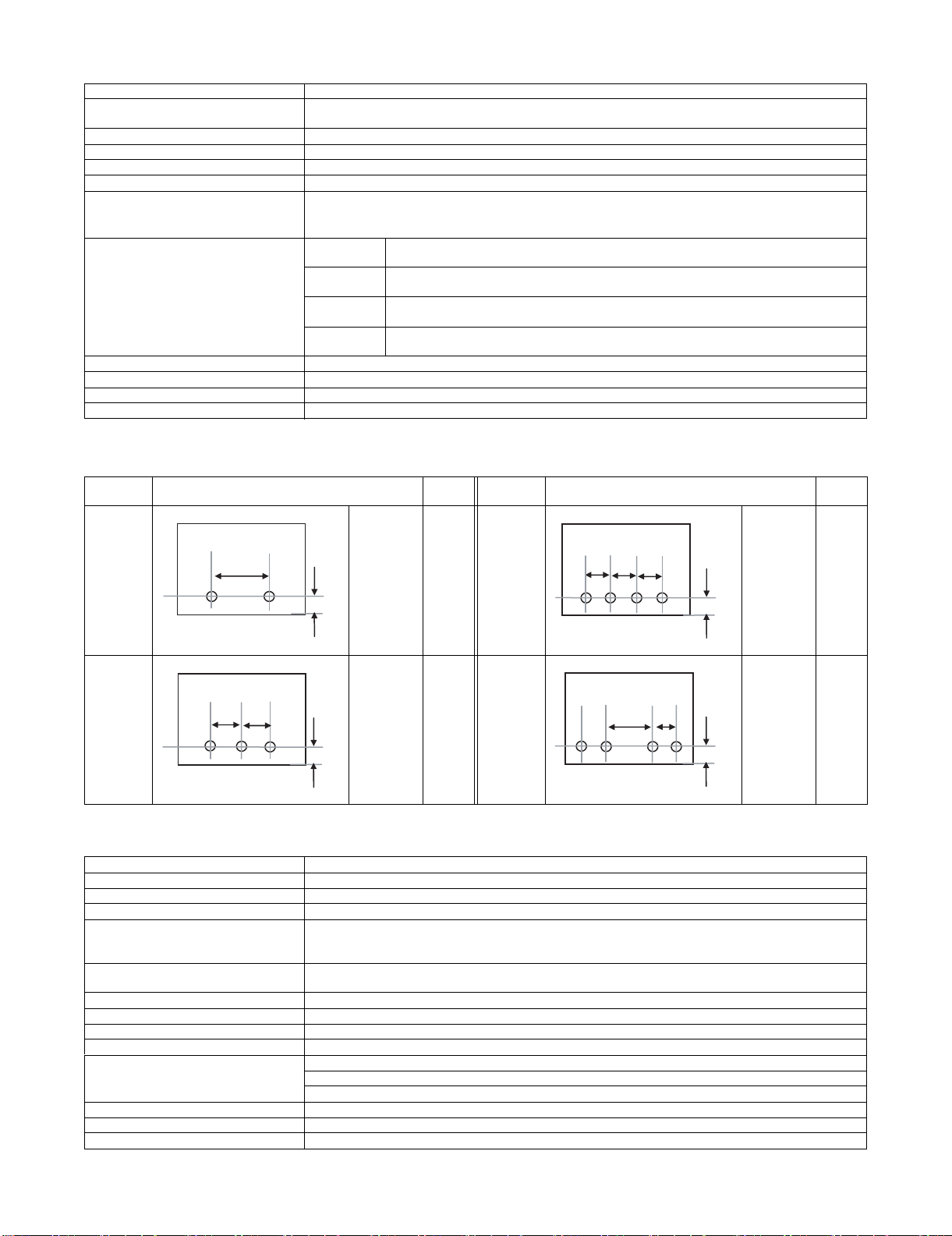
Kind Hole position
2 holes
(AR-PN1A)
A: 80±1mm
B: 12±3mm
Hole
size
φ6.5mm 4 holes
Kind Hole position
(AR-PN1C)
B
3 holes
(AR-PN1B)
A: 108±1mm
B: 12±3mm
φ8.0mm 4 holes
(wide)
(AR-PN1D)
3. MX-RBX1
Type Paper pass unit
Paper reception reference Center referance
Receiving speed 62 to 450mm/sec (23 to 45cpm)
Receiving and sending speed 23 to 45cpm
Paper weight Thin paper:
Plain paper:
Heavy paper:
Transportable paper sizes A3W, A3, B4, A4, A4R, B5, B5R, A5R, 16K, 16KR
12" x 18", 11" x 17", 8.5" x 14", 8.5" x 13", 8.5" x 11", 8.5" x 11"R, 5.5" x 8.5"R, 7.25" x 10.5"R
External dimensions (W x D x H) 555 x 535 x 165 (mm), 21 27/32 x 21 1/16 x 6 1/2 (inch)
Weight Approx. 7kg (15.4 lbs)
Power source Supplied by saddle finisher
Power consumption Included with saddle finisher power consumption
Interface Mechanical: Fixed to the main unit with screws.
Electrical: Cable connection from the finisher
Control: Controlled by the communication command from the main unit through the finisher.
Installation/maintenance Installed by service personnel
Optional detection Auto detection supported
Packaged items Parts for mounting, installation cautionary note
55 to 59g/m
60 to 105g/m
106 to 209g/m
2
(15 to 16 lbs)
2
(16 to 28 lbs)
2
(28 to 56 lbs)
A: 80±1mm
B: 12±3mm
A: 70±1mm
B: 12±3mm
C: 21±1mm
Hole
size
φ6.5mm
φ6.5mm
MX-FNX2/AR-PN1/MX-RBX1 SPECIFICATIONS 2 – 2

âºíuÇ´
[4] EXTERNAL VIEWS AND INTERNAL STRUCTURES
Service Manual
1. Part names and functions
A. External view
1
6
3
5
1 Staple compiler 4 Front cover
2 Top cover 5 Saddle stitch tray
3 Staple section 6 Offset tray
B. Internal structure
(1) Finisher section
1 2 3 754 6
2
4
1614 1513 17128 9 10 11
1 Paper exit tray 10 Stapler
2 Alignment plate (Front, back) 11 Saddle section
3 Paddle 12 Book making stopper
4 Paper exit roller 13 Book making tray
5 Process tray stopper 14 Bundle transport roller
6 Transport roller 15 Book making exit roller
7 Punch section (Option) 16 Paper folding roller
8 Paper exit belt 17 Paper pushing plate
9 Bundle exit roller
MX-FNX2/AR-PN1/MX-RBX1 EXTERNAL VIEWS AND INTERNAL STRUCTURES 4 – 1
(2) Punch section (Option: AR-PN1A/B/C/D)
31 2 4
1 Die 3 Punch
2 Cam 4 Punch dust box
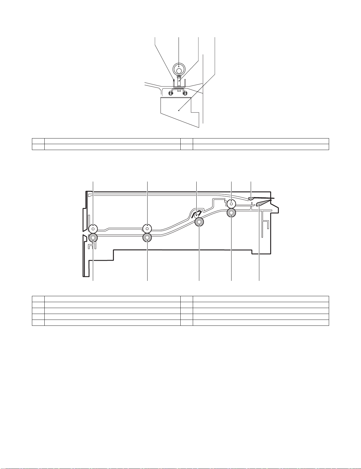
(3) Interface transport section (MX-RBX1)
1
5
1 Paper exit roller 6 Paper exit front roller
2 Paper exit front roller 7 Inlet port rear roller
3 Inlet port rear roller shaft 8 Inlet port roller
4 Inlet port roller 9 Reverse flapper
5 Paper exit roller 10 Upper guide flapper
2
6
3
7
4
8
9
10
MX-FNX2/AR-PN1/MX-RBX1 EXTERNAL VIEWS AND INTERNAL STRUCTURES 4 – 2
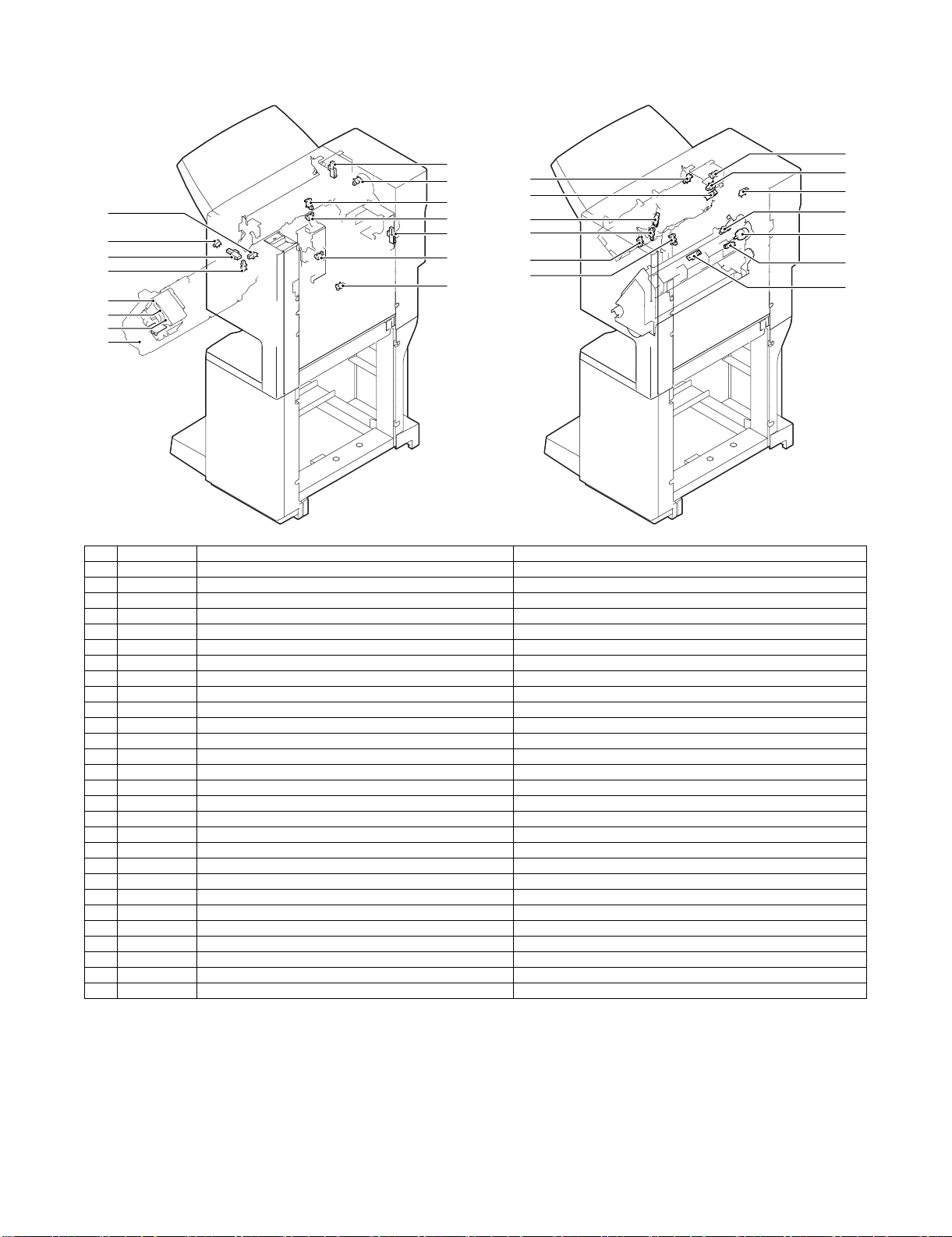
C. Finisher and saddle section
(1) Sensor, switch and clutch
26
5
2
7
6
8
9
23
24
22
14
28
16
4
25
17
13
19
20
21
18
No. Signal Name Active condition
1 FED Entry paper sensor Paper detected: "H"
2 FPDHPD Paddle home position sensor Paddle HP: "H"
3 FARHPD Bundle roller home position sensor Oscillation guide HP: "H"
4 FFJHPD Alignment home position sensor (front) Alignment tray (F) HP: "H"
5 FRJHPD Alignment home position sensor (rear) Alignment tray (R) HP: "H"
6 FAD Alignment tray sensor Paper detected: "H"
7 FOBHPD Exit belt home position sensor Paper exit belt HP: "H"
8 FBED Tray paper sensor Tray paper detected: "H"
9 FSLD Paper level sensor Paper detected: "H"
10 FFPD Bookbinding position sensor Paper detected: "L"
11 FFHPD Bookbinding home position sensor Folding operation HP: "L"
12 FFRHPD Bookbinding roller home position sensor Bundle transport roller HP: "H"
13 FFED Bookbinding paper sensor Paper detected: "H"
14 FFE Bookbinding lock sensor
15 FULD Lift upper sensor Tray upper limit detected: "H"
16 FLLD Lift lower sensor Tray lower limit detected: "H"
17 FLE Lift lock sensor
18 FSTHPD Staple shift home position sensor Stapler HP: "H"
19 FSHPD Staple drive home position sensor Stapler stapling HP: "L"
20 FSPD Self prime sensor Cartridge staple detected: "L"
21 FSD Staple empty sensor Stapler cartridge detected: "L"
22 FFDD Front door sensor Front cover open: "H"
23 FCD Upper cover sensor Upper cover open: "H"
24 FFDDW Front door switch Front door closed: "H"
25 FJSW Joint switch Printer connected: "H"
26 FSSSW Staple safety switch Oscillation guide closed: "H"
27 FCC Bookbinding clutch When drive is transmitted: "H"
28 FMLD Tray middle sensor Tray middle detected: "H"
15
3
1
12
27
11
10
MX-FNX2/AR-PN1/MX-RBX1 EXTERNAL VIEWS AND INTERNAL STRUCTURES 4 – 3
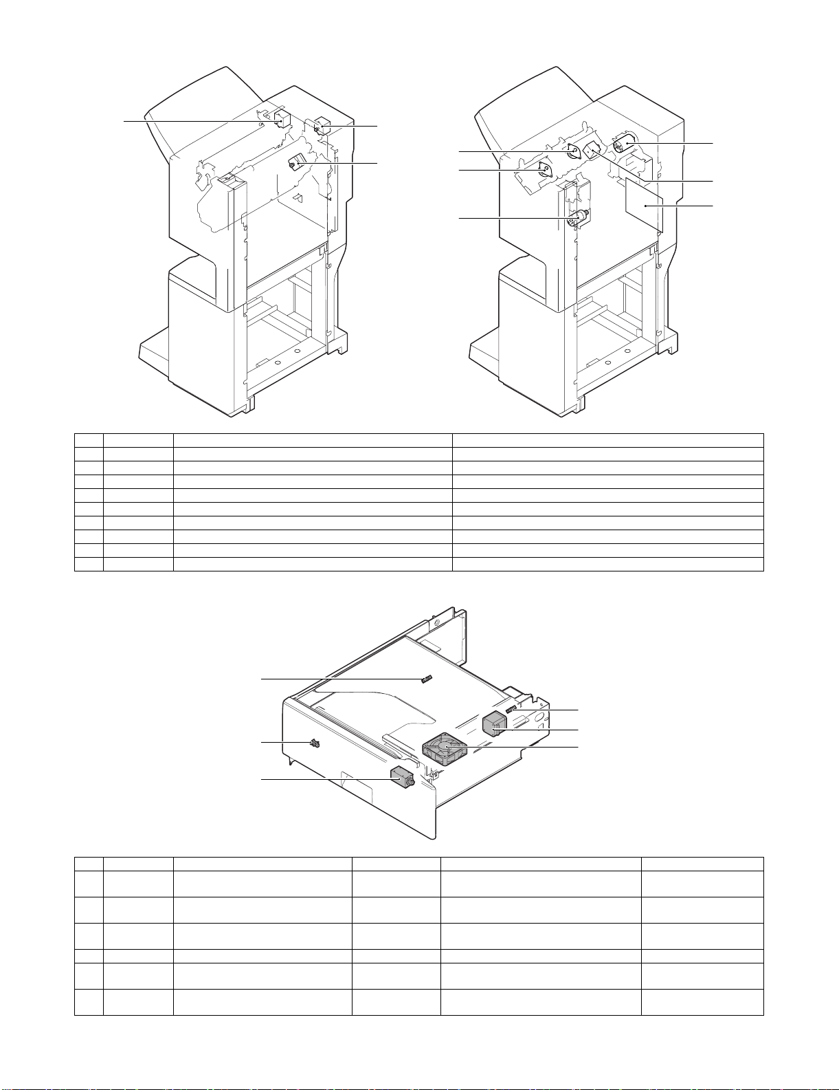
(2) Motor and PCB
2
1
5
8
4
6
No. Signal Name Active condition
1 FFM Transport motor Paper transport
2 FPM Paddle motor Oscillation guide drive, paper exit to offset tray
3 FAM Bundle exit motor Paper exit operation
4 FFJM Alignment motor (front) Alignment plate (F) drive
5 FRJM Alignment motor (rear) Alignment plate (R) drive
6 FLM Lift motor Paper exit tray up/down
7 FFSM Staple motor Stapling/paper folding
8 FSM Staple shift motor Staple unit sliding
9 PBA-CONT Control PCB Finisher control
7
3
9
D. Interface transport section (MX-RBX1)
2
1
3
5
No. Signal Name Type Function/Operation Output
1 FJPID Interface transport unit inlet port sensor Photointerrupter Interface inlet port paper detection LO light is interrupted
2 FJPOD Interface transport unit outlet port
sensor
3 FJPDD Interface transport unit cover sensor Photointerrupter Interface cover open detection Light is interrupted when
4 FJPM Interface transport motor Paper transport roller drive
5 FINRPS Interface reverse path solenoid Drive of the flapper which selects the path in
6 FJFM Interface fan Temperature rise protection fan in the
Photointerrupter Interface outlet port paper detection LO light is interrupted
the finisher and the reverse path
finisher inlet port section
4
6
when paper is provided.
when paper is provided.
the cover is open.
MX-FNX2/AR-PN1/MX-RBX1 EXTERNAL VIEWS AND INTERNAL STRUCTURES 4 – 4
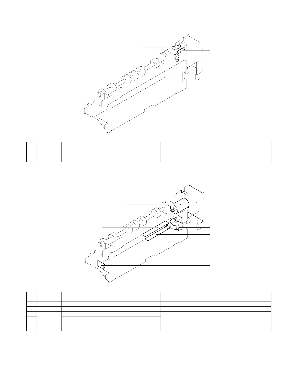
E. Punch section (AR-PN1A/B/C/D)
(1) Sensor
3
1
2
No. Signal Name Active condition
1 FPHPD Punch home position sensor Punch HP detected: "L"
2 FPSHPD Punch side resist home position sensor Punch slide unit HP detected: "H"
3 FPMCK Punch motor lock sensor
(2) Motor and PCB
1
3
6
4
2
5
7
No. Signal Name Active condition
1 FPNM Punch motor Punch drive
2 FPSM Punch side resist motor Punch slide unit transverse move
3 Punch control PCB
4FPTD
FPSD1 – 4
5 Side resist LED PCB
6 FPDD Dust full photo sensor PCB Punch dust full detection
7 Dust full LED PCB
Side resist photo sensor PCB Punch horizontal resist and punch timing detection
MX-FNX2/AR-PN1/MX-RBX1 EXTERNAL VIEWS AND INTERNAL STRUCTURES 4 – 5
âºíuÇ´
[5] OPERATIONAL DESCRIPTION
1. Basic operations
A. Specifications
The finisher serves to deliver sheets coming from its host machine.
The mode of delivery may be non-sort stack, job offset *, or staple
delivery.
The saddle unit built into the finisher is used to fold a stack of
sheets coming from the finisher unit in half for delivery.
The punch unit (option) is designed for installation to the pickup
assembly of the finisher, and is used to punch holes in sheets coming from the host machine.
The above operations are controlled with various commands from
the finisher controller PCB as well as the commands from the
punch controller PCB.
Punch unit drive
system (punch unit;
option)
Alignment drive system
Stapler drive system
Delivery drive system
Feed drive system
Control system
Tray drive system
Saddle section
drive system
Interface pass
drive system
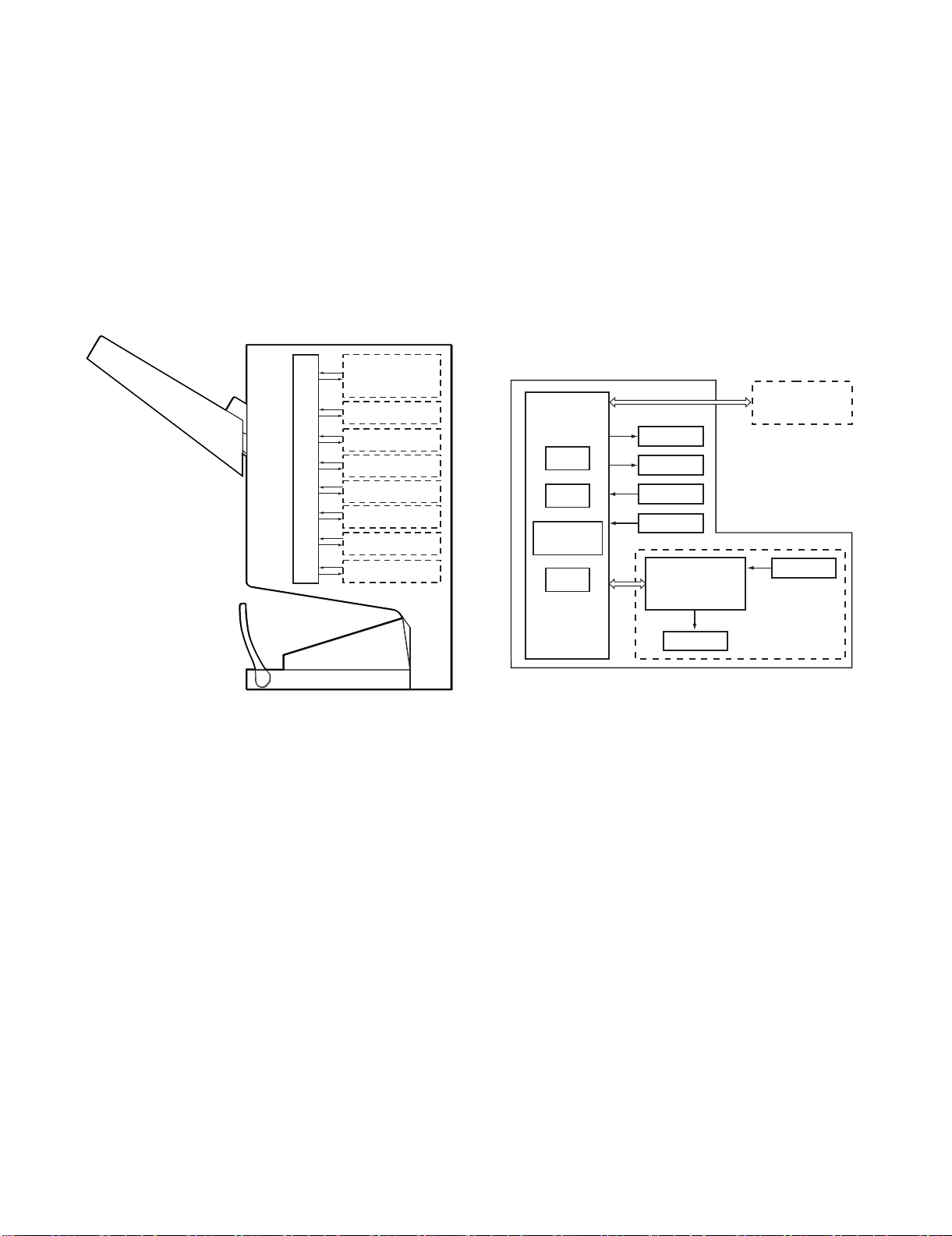
B. Outline of the Electrical Circuitry
Service Manual
The sequence of finisher operations is controlled by the finisher
controller PCB. The finisher controller PCB is a 16-bit microprocessor (CPU), and is also used for combination with the host machine
(serial).
The finisher controller PCB drive motors and other loads in
response to the various commands from the host machine. It also
communicates such data as on the states of various sensors and
switches to the host machine by way of the serial communication
line.
The ICs mounted to the finisher controller PCB have the following
functions:
• IC13 (CPU): Controls sequence of operations.
• IC12 (EEP-ROM): Backs up adjustment settings.
• IC6: Stores sequence programs.
• IC11 (expansion port): I/O port
The flow of signals between finisher and options controller is shown
as below.
Finisher unit
Host machine DC
Finisher
controller
PCB
IC13
CPU
IC12
EEP-ROM
IC11
Communication
IC
IC6
ROM
Motor
Clutch
Switch
Sensor
Punch unit (option)
Punch controller
PCB
controller PCB
CPU
Sensor
*: The position of delivery is shifted to the front/rear for each stack
to assist sorting.
Motor
MX-FNX2/AR-PN1/MX-RBX1 OPERATIONAL DESCRIPTION 5 – 1

C. Inputs to and Outputs from the Finisher
When the drive is transmitted,
‘1’.
Switches between ‘1’and
‘0’ according to the
direction of motor rotation.
Switches between ‘1’and
‘0’ according to the
direction of motor rotation.
Switches between ‘1’and
‘0’ according to the
direction of motor rotation.
Switches between ‘1’and
‘0’ according to the
direction of motor rotation.
Switches between ‘1’and
‘0’ according to the
direction of motor rotation.
Finisher controller PCB
Feed motor
FEEDMTR_A
+24V
CN10-1
-1
CN62-5
Paddle motor
+24V
FPM
FFC
B_CLU
+24V
CN72
-1
-2
-2
-1
CN18-1
-2
Binding clutch
Bundle exit motor
+24V
FAM
Alignment motor
(front)
+24V
FFJM
Alignment motor
(rear)
+24V
FRJM
-2
-3
-4
-5
-6
FFM
-2
-3
-4
-5
-6
CN56
-6
-5
-4
-3
-2
-1
FEEDMTR_*A
FEEDMTR_B
FEEDMTR_*B
PDLMTR_A
PDLMTR_*A
PDLMTR_B
PDLMTR_*B
CN10-7
-8
-9
-10
-11
-12
-1
-2
-3
-4
-5
-6
CN57
-6
-5
-4
-3
-2
-1
EJCTMTR_A
EJCTMTR_*A
EJCTMTR_B
EJCTMTR_*B
CN13-1
-1
-2
-3
-4
-5
-6
-2
-3
-4
-5
-6
CN59
-6
-5
-4
-3
-2
-1
CN3-1
-2
-3
-4
-5
FJOGMTR_A
FJOGMTR_*A
FJOGMTR_B
FJOGMTR_*B
CN63-1
-2
-3
-4
-5
-4
-3
-2
-1
CN64-5
CN3-6
-7
-8
-9
-10
CN65-1
-2
-3
-4
-5
-4
-3
-2
-1
RJOGMTR_A
RJOGMTR_*A
RJOGMTR_B
RJOGMTR_*B
Finisher controller PCB
Lift motor
SIFTMTR_1
Switches between ‘+’and
‘–’ according to the
direction of motor rotation.
CN6-1
-2
FLM
-2
-1
CN70
-2
-1
SIFTMTR_0
-2
-1
-2
-1
-2
-1
CN70
-2
-1
Staple motor
BINDMTR_1
Switches between ‘+’and
‘–’ according to the
direction of motor rotation.
CN6-3
-4
FFSM
BINDMTR_0
CN71
Controller PCB
• Inputs to the Finisher Controller PCB (1/2)
Entry paper
sensor
Paddle home
position sensor
Bundle roller
home position
sensor
Aligning plate
home position
sensor (front)
Aligning plate
home position
sensor (rear)
Alignment
tray sensor
Delivery belt
home position
sensor
Tray paper sensor
Paper surface
sensor
Bookbinding
position sensor
FED
FPDHPD
FAR HPD
FFJHPD
FRJHPD
FAD
FOBHPD
FBED
FSLD
FFPD
CN44-3
CN51-1
CN55-3
CN23-3
CN36-3
CN30-3
CN31-3
CN32-3
CN35-3
CN39-3
CN43-1
CN42-3
-3
-1
-2
-2
-3
-2
CN54-1
-3
-1
-2
-2
-1
-2
-1
-2
CN29-1
-3
-1
-2
-2
-4
-6
-1
-2
-5
-7
-9
-1
-8
-2
CN34-1
-3
-1
-2
-2
CN38-1
-2
-2
-3
-1
CN53-3
CN28-9
CN33-3
CN37-9
-1
-2
-1
-2
-7
-8
-6
-4
-5
-3
-1
-2
-1
-2
-8
-7
CN16-10
CN9-1
CN9-7
CN4
CN5-13
CN5-1
CN5-10
CN16-1
-12
-11
-3
-2
-9
-8
-3
-2
-15
-14
-3
-2
-4
-6
-5
-7
-9
-8
-12
-11
-2
-3
Finisher controller PCB
+5V
ENT_S
+5V
PDL_HP
+5V
BDL_ROL_HP
+5V
FJOG_HP
+5V
RJOG_HP
+5V
ADJ_TRAY_S
+5V
EJCT_BLT_HP
+5V
TRY_EMPS
+5V
LVL_S
+5V
BIND_P
BIND_L
When the sensor
detects paper, ‘1’ .
When the paddle is at
home position, ‘1’.
When the swing guide
is at home position, ‘1’.
When the aligning
plate (front) is at
home position, ‘1’.
When the aligning
plate (rear) is at
home position, ‘1’.
When the sensor
detects paper, ‘1’.
When the delivery belt
is at home position, ‘1’.
When paper is present
on the tray,‘1’.
When the paper
surface is detected,
‘1’.
When paper is
detected, ‘0’.
When LED is lit, ‘1’.
• Outputs from the Finisher Controller PCB (1/2)
• Inputs to the Finisher Controller PCB (2/2)
FFHPD
Bookbinding
home position
sensor
Bookbinding
roller home
position sensor
Bookbinding
paper sensor
Bookbinding
lock sensor
Lift upper sensor
Lift lower sensor
Lift lock sensor
Front door sensor
Upper cover sensor
Tray middle sensor
Joint switch
Front door switch
Stapler safety
switch
FFRHPD
FFED
FFE
FULD
FLLD
FLE
FFDD
FCD
FMLD
FJSW
N. O.
FFDDW
N. O.
FSSSW
N. O.
CN40-3
CN41-3
CN47-3
CN52-1
CN50-3
CN49-3
CN48-3
CN25-3
CN24-3
CN73-3
-1
-2
-1
-2
-1
-2
-2
-3
-1
-2
-1
-2
-1
-2
-1
-2
-1
-2
-1
-2
CN69-2
CN68-2
CN66-2
-1
-1
-1
CN38-4
-6
-5
-7
-9
-8
CN16-4
CN37-6
-4
-5
-3
-1
-2
CN15-1
CN15-10
CN15-7
CN15-4
CN19-1
• Outputs from the Finisher Controller PCB (2/2)
Finisher controller PCB
+5V
CN9-6
CN4-7
CN4-4
CN8-6
CN8-4
CN8-2
-6
BIND_HP
-5
-7
+5V
-9
BIND_ROL_HP
-8
+5V
-3
BIND_EMPS
-2
+5V
-5
BIND_CLK
-4
+5V
-12
SIFT_UPLMT
-11
+5V
-9
SIFT_DNLMT
-8
+5V
-6
SIFT_CLK
-5
+5V
-9
FDOOR_S
-8
+5V
-6
TOPCOV_S
-5
+5V
-3
PAPE R_ F
-2
+24VP
-5
-3
-1
JOINT SW
FRONT SW
STPLSAFE SW
When at folding home
position, ‘0’.
When the stack feed roller
(upper) is at home position, ‘1’.
When the sensor
detects paper, ‘1’.
When the staple/fold motor is
rotating, alternates between
‘1’ and ‘0’.
When the tray is at the
upper limit, ‘1’.
When the tray is at the
lower limit, ‘1’.
While the lift motor
is rotating, alternates
between ‘1’ and ‘0’.
When the front door
is open, ‘1’.
When the upper cover
is open, ‘1’.
When the paper is
full, ‘1’.
When connected to
the host machine, ‘1’.
When the front
door is closed, ‘1’.
When the swing
guide is closed, ‘1’.
MX-FNX2/AR-PN1/MX-RBX1 OPERATIONAL DESCRIPTION 5 – 2
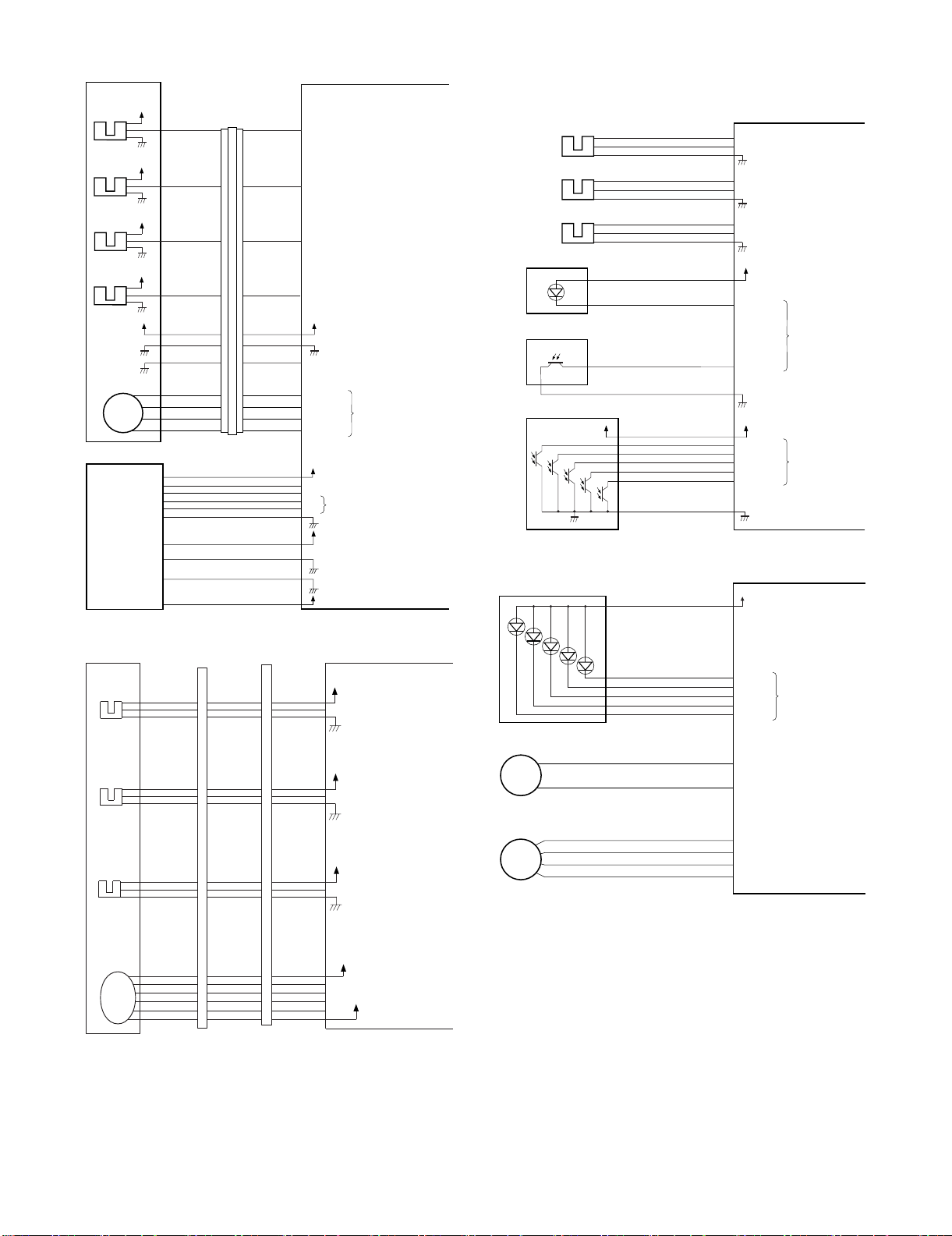
• Inputs to and Outputs from the Finisher Controller PCB (1/2)
Punch controller PCB
-1
J2008-3
+5V
PUNCH
-2
-6
J1006-4
-5
SREG1*
SREG2*
SREG3*
-9
-10
-11
J1007-12
-13
SREG4*
-8
PAEND*
-7
Horizontal
registration
home position
sensor
FPMCK
-1
J2009-3
+5V
CLOCK
-2
-9
J1006-7
-8
Punch home
position sensor
+5V
+5V
PT1
PT2
PT3
PT4
PT5
FPSHPD
FPHPD
-1
J2007-3
+5V
SLIDE
-2
-3
J1006-1
-2
Punch motor
lock sensor
Side resist photo sensor PCB (FPTD)
DUSTLED
Waste full LED PCB
J1005-1
PT131
LED121
DUSTPTR
+5V
4
Waste full photosensor PCB (FPDD)
-2
J1005-3
When the hole puncher is
at home position, ‘0’.
While the punch motor
is rotating, alternates
between ‘0’and ‘1’.
When the punch slide
unit is at home position,
‘1’.
When paper is
detected, ‘0’.
When the light is
blocked, ‘0’.
Stapler unit
Staple shift home
position sensor
FSTHPD
Staple driver home
position sensor
FSHPD
Staple empty
sensor
FSD
Self prime
sensor
FSPD
Staple shift motor
FSM
Host
machine
+5V
+5V
+5V
+5V
+5V
CN72-5
CN72-4
CN72-3
CN72-2
CN72-6
CN72-1
CN72-7
CN72-10
CN72-11
CN72-12
CN72-13
CN72A-5
CN72A-4
CN72A-3
CN72A-2
CN72A-6
CN72A-1
CN72A-7
CN72B-5
CN72B-4
CN72B-3
CN72B-2
CN72A-5
CN72A-4
CN72A-3
CN72A-2
CN72A-6
CN72A-1
CN72A-7
CN72B-5
CN72B-4
CN72B-3
CN72B-2
CN11-3
CN11-4
CN11-5
CN11-6
CN11-2
CN11-7
CN11-1
CN7-3
CN7-4
CN7-5
CN7-6
CN2-1
CN1-5
CN1-3
CN1-2
CN1-1
SLID_HP
STPL_HP
HOOK_S
SELF_P
STPL_CNCT
SLIDMTR_A
SLIDMTR_*A
SLIDMTR_B
SLIDMTR_*B
-3
GND
-4
GND
-5
TXD
-7
RXD
-6
+5V
+24V
+24V
+5V
Finisher controller PCB
When the stapler is at home
position, ‘1’.
When the stapler is at
stapling home position, ‘0’.
When the cartridge has
staples, ‘0’.
When the staple is at top
the stapler, ‘0’.
When the stapler is
connected, ‘0’.
Switches between ‘1’and
‘0’ according to the direction
of motor rotation.
Communication line
• Inputs to and Outputs from the Finisher Controller PCB (2/2)
-2
-3
Finisher control PWB
+5V
"0" when paper is detected.
LVL_E_S
Interface transport
unit inlet port
sensor
FJPID
CNFJ2-1
-3
-2
CNFJ1-
-17
-16
CNFJ1-
-17
-16
CN73C-1
-2
-3
CN73A-8
-7
-6
CN21-
D. Inputs to and Outputs from the Punch
Controller PCB (option)
• Inputs to and Outputs from the Punch Controller PCB
• Outputs from the Punch Controller PCB
LEDON5
LEDON4
LEDON3
LEDON2
LEDON1
Punch controller PCB
When ‘1’, LED goes ON.
Side resist LED PCB (FPSD)
LED5
LED4
LED3
LED2
LED1
J1007-6
+5V
-1
-5
-4
-3
-2
Interface transport
unit outlet port
sensor
FJPOD
Interface transport
unit cover sensor
FJPDD
Interface
transport
motor
FJPM
Punch motor
J1002-1
CNFJ3-1
-3
-2
CNFJ4-3
-2
-1
CNFJ5
-4
-3
-1
-2
-5
CNFJ1-
-14
-13
CNFJ1-
-11
-10
CNFJ1-2
-7
-6
-5
-4
-3
CNFJ1-
-14
-13
CNFJ1-
-11
-10
CNFJ1-2
-7
-6
-5
-4
-3
CN73C-4
CN73C-7
CN73D-2
CN73D-9
CN73A-5
-5
-4
-6
-3
CN73A-2
-1
-8
CN73B-8
CN73B-
-6
-4
-5
-5
-6
-4
-3
-7
-2
-8
MX-FNX2/AR-PN1/MX-RBX1 OPERATIONAL DESCRIPTION 5 – 3
CN21-4
-5
LVL_P_S
-6
CN21-7
-8
LVL_C_S
-9
CN19-
-2
A
-3
*A
-4
B
-5
*B
-6
+5V
"0" when paper is detected.
+5V
"0" when the interface
transport cover is open.
+24V
The pulse signal is
switched depending
on the motor RPM.
+24V
FPNM
Punch side resist motor
FPSM
J1001-1
-2
-2
-3
-4
A
B
A*
B*
Switches between ‘+’
and ‘–’ according to
the direction of motor
rotation.
Switches the pulse
signals according to
the rotation of the motor.
2. Feed/Drive System
(
y)
A. Outline
The machine performs the following in response to the commands
coming from its host machine on the sheets arriving from the host
machine for delivery: simple stacking, job offset, and stapling or
folding (in two).
If a punch unit (option) is installed, the sheets are pouched and
delivered to the delivery tray.
Sheets may be delivered in either of five ways (including one for
the punch unit):
Normal deliveryDelivery method
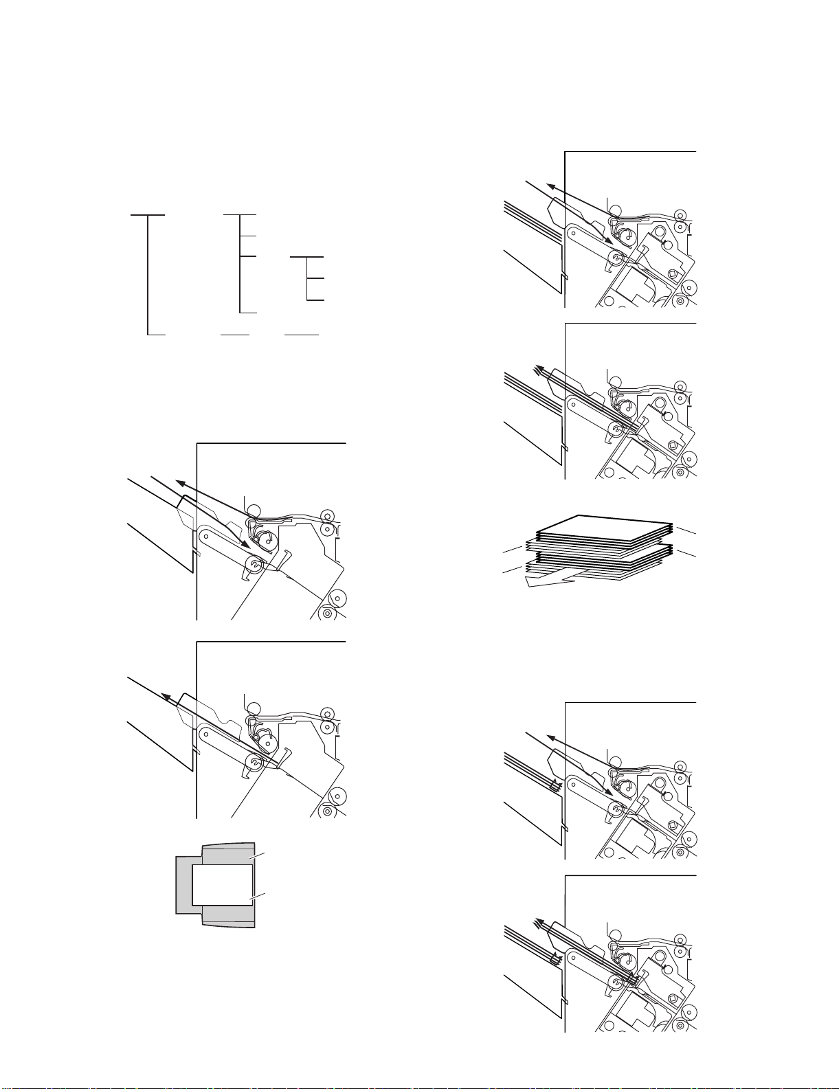
(1) Normal Delivery
a. Simple Stacking
The machine pulls in the sheet once to the processing tray and
then delivers it to the delivery tray.
Simple stacking
Job offset
Stapling Front 1-point stapling
Rear 1-point stapling
Middle 2-point stapling
Punching
StitchingSaddle delivery
Middle 2-point stapling
b. Job Offset
The machine pulls the sheet once to the processing tray. It then
moves the sheet to the front or the rear using the aligning plate.
When it has deposited a specific number of sheets, it delivers them
in the form of a aligning plane. When the number of sheets stacked
on the processing tray reaches a specified value, the sheets are
delivered in a form of a stack.
Tray
Paper
Results of offset delivery (4 jobs)
4th set
3rd set
1st set
direction of deliver
2nd set
c. Stapling
The machine stacks sheets coming from its host machine on the
processing tray. When the number of sheets stacked on the processing tray reaches a specified value, the finisher staples them
delivers the stapled stack to the delivery tray.
MX-FNX2/AR-PN1/MX-RBX1 OPERATIONAL DESCRIPTION 5 – 4
d. Saddle Delivery
Staple motor
drive signal BINDMTR
Bookbinding lock sensor
detect signal BIND_CLK
Finisher controller PCB (1/2)
Lift motor drive signal SIFTMTR
Bundle exit motor drive signal EJCTMTR
Staple slide motor drive signal
SLIDMTR
Paddle motor
drive signal PDLMTR
Alignment motor (rear)
drive signal RJOGMTR
Bind clutch
drive signal B_CLU
Interface transport motor
drive signal RIM
Alignment motor (front)
drive signal FJOGMTR
FFE
FRJM
FPM
FFSM
FFC
FAM
FSM
FLM
FFJM
FJPM
FFM
Finisher controller PCB (2/2)
Feed motor
drive signal FEEDMTR
Finisher controller PCB
FFPD
Bookbinding position
detect signal BIND_P
FED
Entry paper detect signal
ENT_S
The machine deposits a stack of sheets on the processing tray, staples it (middle 2-point), and then moves it to the saddle unit. The
saddle unit folds the stack in two, and delivers it to the bind tray.
B. Feed/Delivery
(1) Outline
The machine forwards the sheets coming from its host machine to
the delivery tray, processing tray, or saddle unit according to the
type of delivery used. The sheets forwarded to the processing tray
or the saddle unit are offset, stapled, or folded.
The following table shows the motors that are associated with moving and aligning sheets. These motors are controlled (rotated clockwise or counterclockwise) by the microprocessor (CPU) on the
finisher controller PCB.
The paper path is equipped with the sensors shown in the following
figure used to monitor the arrival or passage of sheets.
If a sheet fails to arrive at or move past a specific sensor within a
specific period of time, the finisher controller will assume a jam, and
stops the ongoing operation and, at the same time, communicates
the presence of a jam to the host machine.
Notation Name Description
FFM Feed motor Stepping motor CN10
FPM Paddle motor Stepping motor CN10
FAM Bundle exit motor Stepping motor CN13
FFJM Alignment plate motor
(front)
FRJM Alignment plate motor
(rear)
Stepping motor CN3
Stepping motor CN3
FFSM Staple motor Brush DC motor CN6
FJPM Interface transport motor Stepping motor CN21
Connector on
finisher
controller PCB
Notation Name Description
Connector on
controller PCB
FED Entry paper sensor Photointerrupter CN16
FFPD Bookbinding position
Photointerrupter CN16
sensor
finisher
MX-FNX2/AR-PN1/MX-RBX1 OPERATIONAL DESCRIPTION 5 – 5

C. Job Offset
(1) Outline
"Job offset" refers to the operation by which the machine delivers a
set of sheets with them pulled forward or backward for sorting.
Switching between the forward and backward directions is made
using an aligning plate (front) and an aligning plate (rear).
The sheet coming between the delivery rollers is fed onto the processing tray and then fed toward the stopper by the paddle.
A swing guide is at the up position while a sheet is being pulled
onto the processing tray or during alignment. It is at the down position during stack feeding, stack delivery, or stapling.
At power-on, the finisher controller PCB drives the aligning motor
(front) (FFJM) and the aligning motor (rear) (FRJM) to return the
two aligning plates to their home positions.
Sensor Symbol Connector
Aligning home position sensor (front) FFJHPD CN4-3
Aligning home position sensor (rear) FRJHPD CN5-15
Stack roller home position sensor FARHPD CN9-9
Paddle home position sensor FPDHPD CN9-3
(3) Offset Operation
Each sheet is pulled forward or backward using the aligning plate
(front) and the aligning plate (rear).
The offset operation is performed each time a sheet is pulled onto
the processing tray.
Offsetting in the forward direction
Aligning plate (rear)
Sheet to be offset
Tr ay
Aligning plate (front)
Function Motor Symbol
Drives the aligning plate (front) Aligning motor (front) FFJM
Drives the aligning plate (rear) Aligning motor (rear) FRJM
Drives the swing guide drive Paddle motor FPM
Drives the paddle (feeds paper) Paddle motor FPM
Aligning home position sensor (rear)
(FRJHPD)
Light-shielding plate
Paper
Alignment motor (front)
(FFJM)
Aligning plate
(front)
(Front)
Light-shielding plate
Aligning home position sensor (front)
(FFJHPD)
Aligning plate
(rear)
Alignment
motor (rear) (FRJM)
(2) Processing Tray Paper Stacking Operation
A sheet coming between the delivery rollers is fed onto the processing tray. Then, the paddle taps on the sheet surface to locate
the sheet against the processing tray stopper.
Paper
Aligning plate
Paddle
Stack delivery roller (upper)
Offsetting in the backward direction
Aligning plate (rear)
Sheet to be offset
Tray
Aligning plate (front)
(4) Stack Delivery Operation
Stack delivery takes place when 1 sheet of large-size paper or 25
sheets of small-size paper have been stacked on the processing
tray with them offset in either direction.
The paddle motor (FPM) rotates and the swing guide descends to
hold the paper stack between the upper and lower stack delivery
rollers. The stack delivery motor (FAM) rotates in the forward direction to rotate the delivery rollers, feeding the paper stack in the
delivery direction. The delivery belt home position sensor is turned
OFF. The delivery motor is driven a specified number of pulses,
causing the swing guide to ascend. Next, the paper delivery motor
is driven. Next, the delivery motor is driven to deliver the paper
stack with the nails of the delivery belt that rotates in sync with the
stack delivery rollers.
Delivery belt
Swing guide
Swing guide
Processing tray stopper
Stack delivery roller (lower)
MX-FNX2/AR-PN1/MX-RBX1 OPERATIONAL DESCRIPTION 5 – 6

Job offset sequence
Start signal
Entry paper sensor
(FFD)
Alignment tray sensor
(FAD)
Feed motor (FEM)
Bundle exit motor(FAM)
Delivery belt home
position sensor (FOBHPD)
Paddle motor (FPM)
Paddle home position
sensor (FPDHPD)
Bundle roller homeposition
sensor (FARHPD)
Staple safety switch
(FSSSW)
Alignment motor (front)
(FFJM)
Alignment home position
sensor (front) (FFJHPD)
Alignment motor (rear)
(FRJM)
Alignment home position
sensor (rear) (FRJHPD)
Host machine delivery signal
∗
4 ms (A4)
∗
Variable by the size
60msec
4ms(A4)
∗
30msec
∗∗
4ms(A4)
220msec
: CW rotation : CCW rotation
4ms(A4)
3. Stapling Operation
A. Outline
Staple operation is performed to staple a specified sheets of paper
using a stapler unit.
The stapling position depends on the staple mode and paper size.
When the machine starts immediately after power-on, the finisher
controller PCB drives the staple shift motor (FSM) to return the stapler unit to the home position. The stapler unit starts moving toward
the front of the stapler frame. It stops when the staple shift home
position sensor (FSTHPD) on the slide PCB located under the stapler unit. Next, the staple shift motor (FSM) is driven a specified
number of pulses. The stapler unit moves to rear standby position
at the back of the machine, entering the standby state.
B. Stapling Operation
When stacking and alignment of paper on the processing tray are
complete, the finisher controller PCB drives the paddle motor
(FPM) in the reverse direction and lowers the swing guide. When
the swing guide descends, the paper stack is sandwiched between
the upper and lower stack delivery rollers.
The finisher control PCB shifts the stapler according to the specified staple position to perform stapling. (Only for B5-R, 1-position
bottom stapling is made at the rear side of 2-posiiton stapling.)
When the stapler shifts toward you, the process tray stopper is put
down to the lower side.
Paper stack
Swing guide
Stack delivery roller (upper)
Processing tray
stopper
Delivery tray
Paddle motor (FPM)
Stack
delivery
roller
(lower)
Stapler
Bundle roller home
position sensor
(FARHPD)
Light-shielding plate
Sensor Symbol Connector Function Remarks
Staple shift
home position
sensor
FSTHPD CN11-3 Detects the home
position for the
stapler moving
back and forth.
Staple drive
home position
sensor
Self prime
sensor
FSHPD CN11-4 Detects the home
position for the
stapling operation
FSPD CN11-5 Detects presence
or absence of
In the
stapler
In the
stapler
staples in the
cartridge.
Staple empty
sensor
FSD CN11-6 Cartridge empty
detection
In the
stapler
Function Motor Symbol Remarks
Moves the stapler. Staple shift motor FSM —
Performs stapling operation Staple motor FFSM —
Stapler
(Deliver direction)
Light-shielding plate
Staple
shift motor
(FSM)
Paper stack
—
Staple safety
switch (FSSSW)
Swing guide
Stack delivery
roller (upper)
Stack delivery
roller (lower)
Staple shift home position sensor (FSTHPD)
MX-FNX2/AR-PN1/MX-RBX1 OPERATIONAL DESCRIPTION 5 – 7

C. Delivery Operation after Stapling
When stapling is complete, the finisher controller PCB drives the
stack delivery motor (FAM) in the forward direction to feed the
paper stack (sandwiched between the stack delivery rollers) in the
delivery direction. The delivery belt home position sensor (FOBHPD) is turned OFF. The stack delivery motor (FAM) is driven a
specified number of pulses, causing the swing guide to ascend. At
the same time, the staple shift motor (FSM) is driven to return the
stapler back to the standby position, followed by driving of the stack
delivery motor (FAM). Then, the paper stack is delivered with the
nails of the delivery belt that rotates in sync with the stack delivery
rollers.
Paper stack
Swing guide
Delivery tray
Paddle motor (FPM)
Delivery belt
Stack delivery
roller (lower)
Stack roller home position
sensor (FARHPD)
Light-shielding plate
Stapler
D. Stapler Unit
The staple motor (FFSM) is used to perform stapling operation.
This motor rotates the cam one turn for stapling. The home position
of this cam is detected by the staple drive home position sensor
(FSHPD).
The staple motor (FFSM) is rotated in the forward or reverse direction under the control of the macro computer (IC13) on the finisher
controller PCB.
When the staple drive home position sensor (FSHPD) is OFF, the
finisher controller PCB rotates the staple motor (FFSM) in the forward direction until the sensor turns ON, allowing the staple cam to
the original position.
The staple empty sensor (FSD) is used to detect presence/
absence of a staple cartridge in the machine. The self prime sensor
(FSPD) is used to detect presence/absence of staples in the cartridge.
The finisher controller circuit does not drive the staple motor
(FFSM) unless the staple safety switch (FSSSW) is ON (the swing
guide is close). This assures safety in case where you happen to
put your finger in the stapler.
Staple safety
switch (FSSSW)
Swing guide
Stack delivery
roller (lower)
Stack delivery roller
(upper)
Staple drive home position detect signal
Staple empty detect signal
Cartridge detect signal
Finisher controller PCB
FFSM
Staple motor drive signal
MX-FNX2/AR-PN1/MX-RBX1 OPERATIONAL DESCRIPTION 5 – 8
(1) Stapler Movement Controller
The stapler unit is moved by the staple shift motor (FSM). Its home
position is detected by the staple shift home position sensor
(FSTHPD). The stapler waits at the back irrespective of the staple
mode and paper size. After paper has been stacked on the processing tray, the stapler is moved to the specified stapling position
in response to the stapling command from the host machine.
The figure below shows the standby position of the stapler and the
stapling position depending on the staple mode.
1) Front 1-point stapling
The stapler waits at the back. The stapler moves to and
returns from the stapling position for each stapling operation.
4) Middle 2-point stapling (bind mode)
The stapler waits at the back. The stapler moves to and
returns from the stapling position for each stapling operation.
The stapler first staples a paper stack at the rear stapling position and then staples it at the front stapling position.
Standby position
Stapler
Stapling position
Standby position
Stapler
Feed direction
Stopper
Stapling position
2) Rear 1-point stapling
The stapler waits at the back. The stapling position is the same
as the standby position. (Except B5R)
Standby position
Stapling position
Stapler
Feed direction
Stopper
Feed direction
Stapling Operation Sequence
Rear 1-point Stapling of 2 Sheets
Start signal
Entry paper sensor (FED)
Alignment tray sensor
(FAD)
Feed motor (FFM)
Bundle exit motor (FAM)
Exit belt home position
sensor (FOBHPD)
Paddle motor (FPM)
Paddle home position
sensor (FPDHPD)
Bundle roller home
position sensor (FARHPD)
Staple safety switch
(FSSSW)
Alignment motor (front)
(FFJM)
Alignment home position
sensor (front) (FFJHPD)
Staple motor (FFSM)
Staple drive home position
sensor (FSHPD)
Host machine delivery signal
4ms (A4)
Stopper
Stapling position
Stack delivery
Staple
10msec
∗
:CWrotation∗ Variable by the size : CCW rotation
4ms (A4)
∗
20msec
3) Middle 2-point stapling
The stapler waits at the back. The stapler moves to and
returns from the stapling position for each stapling operation.
The stapler first staples a paper stack at the rear stapling position and then staples it at the front stapling position.
Standby position
Stapler
Stapling position
Stopper
Feed direction
Stapling position
MX-FNX2/AR-PN1/MX-RBX1 OPERATIONAL DESCRIPTION 5 – 9

4. Delivery Tray Operation
5. Saddle Unit
A. Outline
The machine has a delivery tray in the finisher unit and a bind tray
in the saddle unit.
The bind tray in the saddle unit is of the fixed type and all the folded
paper stacks are delivered to this tray. This tray has a bind tray
sensor (FFED) to detect presence/absence of paper.
The delivery tray in the finisher unit is moved up and down using a
lift motor (FLM).
The finisher has a tray paper sensor (FBED) to detect presence/
absence of paper on the stack tray.
The home position sensor of the delivery tray is detected by the
paper surface sensor (FSLD). When paper has already been
stacked on the delivery tray, the home position is on the top surface
of the stacked paper. When paper has not yet been stacked on the
delivery tray, the home position is at the position where the edge of
the delivery tray is detected. At power-on, the finisher controller
PCB drives the lift motor (FLM) to return the delivery tray to the
home position.
When the paper coming from the processing tray is stacked on the
delivery tray, the lift motor (FLM) is driven a specified number of
pulses, causing the delivery tray to descend. Clock pulses are
detected by the lift lock sensor (FLE). Then, the delivery tray
returns to the home position for the next stacking operation.
The upper limit of the delivery tray is detected by the lift upper limit
sensor (FULD). When the lift upper limit sensor (FULD) is turned
ON, the finisher controller PCB stops the lift motor (FLM) that is
ascending.
The lower limit of the delivery tray is detected by the lift lower limit
sensor (FLLD). When the lift lower limit sensor (FLLD) is turned
ON, the finisher controller PCB stops the lift motor (FLM) that is
descending.
The finisher unit has a tray middle sensor (FMLD) to detect overstacking of large-size or mixed paper according to the stack height.
A. Basic Operations
(1) Outline
The machine stitches a stack of sheets (middle 2-point), then folds
the stack in two in the finisher. These operations are controlled by
the finisher controller PCB.
The finisher controller PCB is controlled by the commands from the
host machine.
B. Feed/Drive System
(1) Outline
This machine stitches the paper stack coming from the finisher,
folds it, and delivers it to the bind tray in the saddle unit in response
to the commands from the host machine.
That is, the machine performs the following operations:
a. Paper feed-in
b. Stitching
c. Stack feed
d. Folding/delivery
a) Paper feed-in
d) Folding/delivery
b) Stitching
c) Stack feed
Lift upper sensor
(FULD)
Lift lower sensor
(FLLD)
Lift lock sensor
(FLE)
Tray middle sensor
(FMLD)
Lift motor (FLM)
Tray paper sensor
Paper level sensor
Edge
Delivery tray
(FBED)
(FSLD)
a. Paper feed-in
After being aligned on the processing tray, a stack of sheets is
sandwiched between the stack delivery rollers. As the stack delivery rollers rotate, the stack is fed toward the saddle unit.
Stack delivery roller (upper)
Paper stack
Stack delivery roller
(lower)
MX-FNX2/AR-PN1/MX-RBX1 OPERATIONAL DESCRIPTION 5 – 10
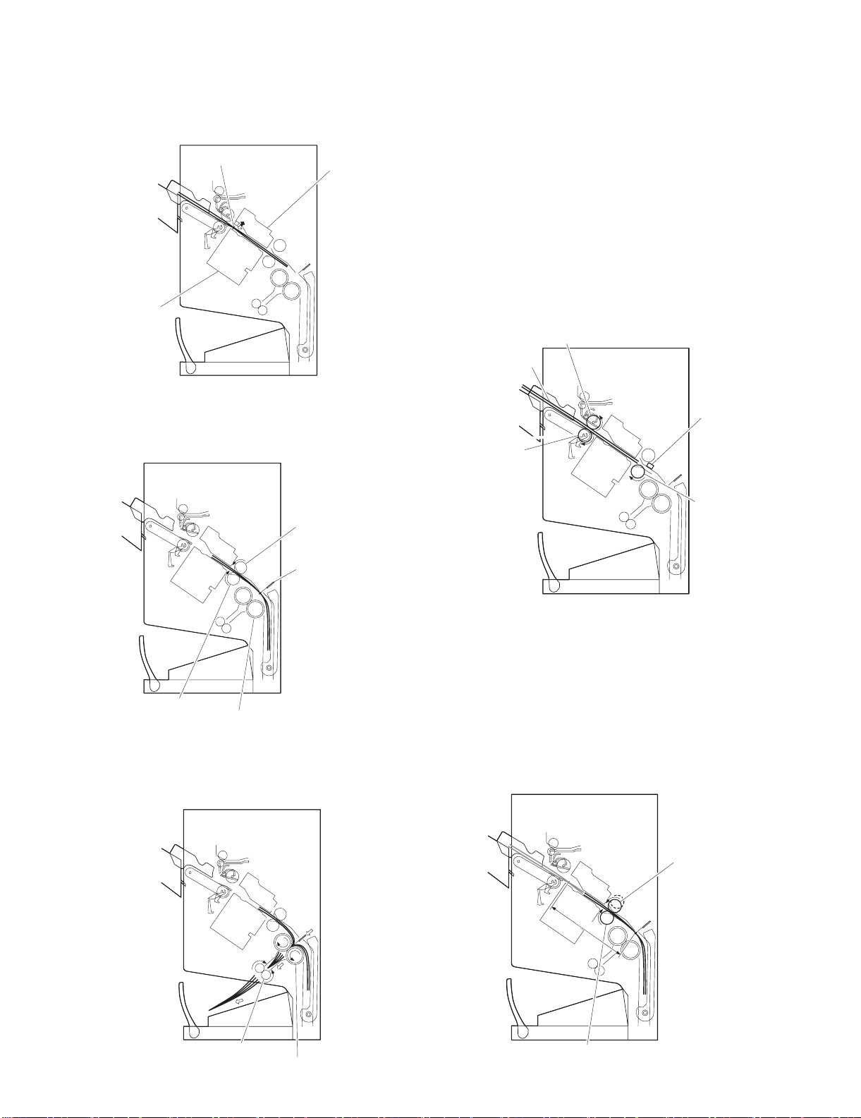
b. Stitching
Stack delivery roller (upper)
Paper stack
Stack delivery roller
(lower)
Stack feed roller (lower)
Fold position sensor
When the center of the paper stack (stitching position) reaches the
stapler's staple position, the stapler stitches the paper stack.
When only one sheet is fed from the host machine, the next step
(stack feed) is performed without performing the stitching operation.
Staple
Stapler (lower)
Stapler (upper)
c. Stack feed
The stack feed rollers feed the paper stack to the stack folding/
delivery position where the center of the stack (stitched position) is
level with the paper pushing plate and paper folding roller's nip part.
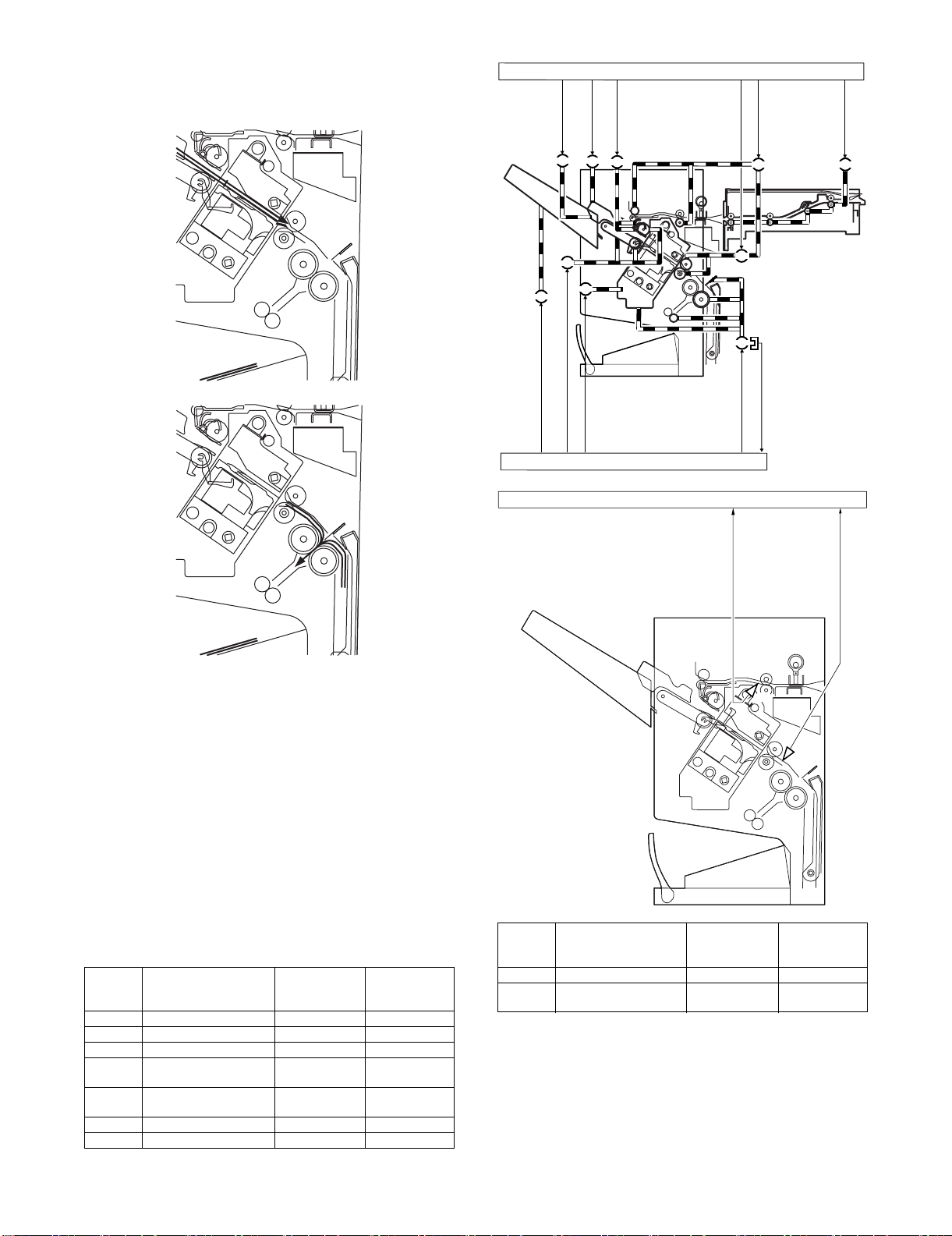
C. Paper Feed System
(1) Outline
The paper feed system feeds a stack of sheets (coming from the
finisher) to the position where the center of the paper stack (stitching position) is aligned to the stapler's staple, allowing the next step
(stitching and folding) to be performed.
When sheets of paper have been stacked and aligned on the processing tray, the paddle motor (FPM) rotates in the reverse direction, causing the swing guide to descend. As the swing guide
descends, the paper stack is sandwiched between the upper and
lower stack delivery rollers. The stack delivery motor (FAM) rotates
in the reverse direction, feeding the paper stack toward the saddle
unit. When the leading edge of the paper stack reaches the binding
position sensor (FFPD), the finisher controller PCB drives the stack
delivery motor (FAM) a specified number of motor pulses to stop
the center of the paper stack (stitching position) at the stapler's staple position. Before the paper stack passes through the stack feed
rollers, the feed motor (FFM) is driven to rotate the stack feed roller
(lower) so that the leading edge of the paper stack is not bent.
Stack feed roller (upper)
Paper pushing plate
Stack feed roller (lower)
Paper fold roller
d. Folding/delivery
The paper pushing plate pushes in the center of the paper stack to
feed it toward the paper fold rollers. Then, the paper fold rollers and
bind delivery rollers deliver the paper stack to the bind tray.
D. Stack Feed System
(1) Outline
The stack feed system feeds the stitched paper stack to the folding
position.
When stitching is complete, the feed motor (FFM) rotates, causing
the stack feed roller (upper) to descend. The paper stack is sandwiched between the stack feed rollers. Then, the bind clutch (FFC)
is turned ON to rotate the feed motor (FFM) in the forward direction, thus feeding the paper stack to the folding position. The feed
amount is equivalent to the number of pulses used to drive the feed
motor (FFM) until the paper stack reaches the folding position.
Stack feed roller (upper)
Feed amount
Bind delivery rollers
Paper fold rollers
MX-FNX2/AR-PN1/MX-RBX1 OPERATIONAL DESCRIPTION 5 – 11
Stack feed roller (lower)
E. Fold/Delivery System
Feed motor (FFM)
Bundle exit motor (FAM)
Paddle motor (FPM)
Paddle home position
sensor (FPDHPD)
Bundle roller home position
sensor (FARHPD)
Staple safety switch
(FSSSW)
Staple shift motor (FSM)
Staple motor (FFSM)
Staple drive home position
sensor (FSHPD)
Bookbinding position
sensor (FFPD)
Bookbinding roller home
position sensor (FFRHPD)
Bookbinding clutch (FFC)
Bookbinding home
position sensor (FFHPD)
Bookbinding paper
sensor (FFED)
: CW rotation : CCW rotation
50msec
Staple
Fold, Delivery
13571msec
(1) Outline
The paper fold mechanism consists of a guide plate, paper fold rollers, and a paper pushing plate.
The guide plate, paper fold rollers, and paper pushing plate are
driven by the staple motor (FFSM). The drive force is transferred
with a combination of gears and cams. Motor operation is monitored by the binding lock sensor (FFE).
Until the paper stack reaches the folding position, the guide plate
covers the paper fold rollers to act as a paper path through which a
paper stack is fed to the saddle unit and to prevent a paper stack
from touching the rollers.
A binding home position sensor (FFHPD) is provided to detect the
positions of the paper fold rollers and paper pushing plate.
The paper stack folded in two by the paper fold rollers is delivered
by bind delivery rollers. The bind delivery rollers are also driven by
the staple motor (FFSM).
A bind tray sensor (FFED) is provided on the bind tray to detect
presence/absence of a paper stack; however, it is not used to
detect a jam.
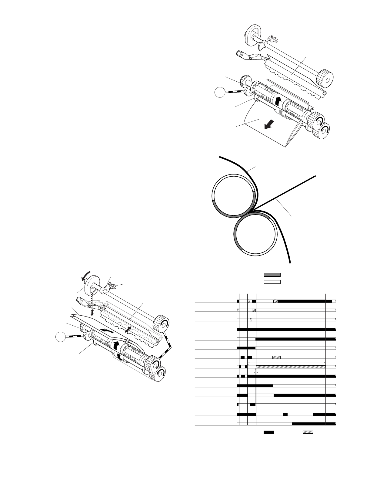
(2) Paper Folding
Paper is folded using paper fold rollers and a paper pushing plate.
Almost concurrently with the start of roller rotation, the paper pushing plate starts operating to push the paper stack into the gap
between the paper fold rollers. When the paper stack is fed about
10 mm with the rotation of the paper fold rollers, the paper pushing
plate returns to the home position. Then, the paper stack is delivered to the bind tray using the paper fold rollers and bind delivery
rollers.
Half the entire surface of each paper fold roller is uncovered
excluding the central area and the area at the left and right ends.
The uncovered surface of the upper paper fold roller comes in
touch with the uncovered surface of the lower paper fold roller only
at the center and left and right ends, allowing a paper stack to be
fed without causing creases. The other half of the upper paper fold
roller that is covered comes in touch with the other half of the lower
paper fold roller that is also covered, allowing a paper stack to be
folded while being fed.
Paper fold roller (upper)
Staple motor
(FFSM)
FFSM
Paper fold roller (lower)
Paper stack
Outlet
Paper stack
Bookbinding home position
sensor (FFHPD)
Paper pushing plate
Inlet
Paper push plate
Paper fold roller (upper)
Staple motor
(FFSM)
Came
Paper stack
FFSM
Paper fold roller (lower)
Sensor flag
Bookbinding home position
sensor (FFHPD)
MX-FNX2/AR-PN1/MX-RBX1 OPERATIONAL DESCRIPTION 5 – 12
Folds/feeds a paper stack.
Feeds a paper stack.
Paper pushing plate
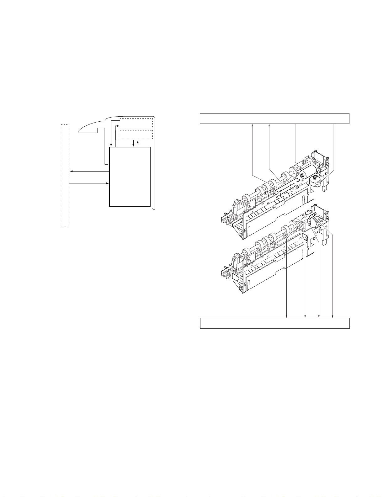
F. Punch Unit (AR-PN1A/B/C/D)
Punch motor
(FPNM)
drive signal
Punch controller PCB (1/2)
Waste full detection signal
(LED121,PT131) FPDD
Punch home position sensor detection signal
(FPHPD)
Horizontal registration home position
(FPSHPD)
detection signal
SREGHP
Punch controller PCB (2/2)
Punch motor lock sensor (
FPMCK
)
detection signal
PUNCHCLK
PT1
LED1
2
3
4
5
5
2
3
4
Trailing edge detection signal
(LED5, PT5) FPTD
Horizontal registration detection
signal (LED1 - 4, PT1 - 4)
FPSD1 - 4
Horizontal registration
motor (FPSM) drive signal
PT131
LED121
(1) Basic Operations
a. Outline
The punch unit is an option, and is designed for installation to the
pickup assembly of the finisher.
The punch unit is not equipped with a paper feeding mechanism,
and the sheets from the host machine move through the punch unit
and then the feed system of the finisher. When the trailing edge of a
sheet from the host machine reaches the punch unit, the sheet is
stopped once, and the punch shaft is rotated to punch a hole along
the trailing edge. These operations are controlled with various commands from the finisher controller PCB as well as the commands
from the punch controller PCB.
Punch drive system
Horizontal registration
drive system
Punch controller PCB
Finisher unit control system
The punch motor (FPNM), punch unit, and sensors make up the
punch slide unit, which moves to the front/rear to suit the selected
paper size. The movement to the front/rear is driven by the punch
horizontal registration motor (FPSM). The home position of the
punch slide unit is detected by the punch horizontal registration
home position sensor (FPSHPD), and the punch horizontal registration motor (FPSM) is a stepping motor.
The punch motor (FPNM) and punch horizontal registration motor
(FPSM) are controlled with various commands from the finisher
controller PCB as well as the commands from the punch controller
PCB. The waste paper occurring as the result of punching is collected in the waste paper case. The case is monitored by the
LED121 on the waste full LED PCB and PT131 on the waste full
photosensor PCB (FPDD).
(2) Punching Operation
a. Outline
The punch unit is located in the pickup assembly of the finisher,
and is used to punch holes in sheets that have been sent from the
host machine and stopped inside it. When the trailing edge of a
sheet reaches the punch unit, the inlet roller of the finisher assembly stops the sheet to punch a hole along the trailing edge of the
sheet.
The punch unit consists of a die and hole puncher (punch blade).
The hole puncher is driven by the punch motor (FPNM). It is
attached to the eccentric cam of the punch shaft, and the rotation of
the punch shaft is converted into reciprocating motion for punching
operation.
The punch motor (FPNM) is a DC motor. The home position of the
punch shaft is detected by the punch home position sensor
(FPHPD). To make sure that the punch motor (FPNM), which is a
DC motor, stops exactly at its home position, the punch motor
(FPNM) is stopped in relation to the count of the clock pulses kept
by the punch motor lock sensor (FPMCK). A single punching operation is executed by rotating the punch shaft 180° from its home
position.
As many as five light-receiving transistors (photosensor PCB) are
mounted over the inlet paper path of the punch unit; on the other
hand, as many as five LEDs (LED PCB) are mounted under the
path, together serving as five sensors. The frontmost sensor
(LED5, PT5) is used as a trailing edge sensor (FPTD) to detect the
training edge of sheets, and the remaining four (LED1 through
LED4, PT1 through PT4) are used as horizontal registration sensors (FPSD1 through FPSD4) to detect the rear position of sheets
when punching holes.
MX-FNX2/AR-PN1/MX-RBX1 OPERATIONAL DESCRIPTION 5 – 13

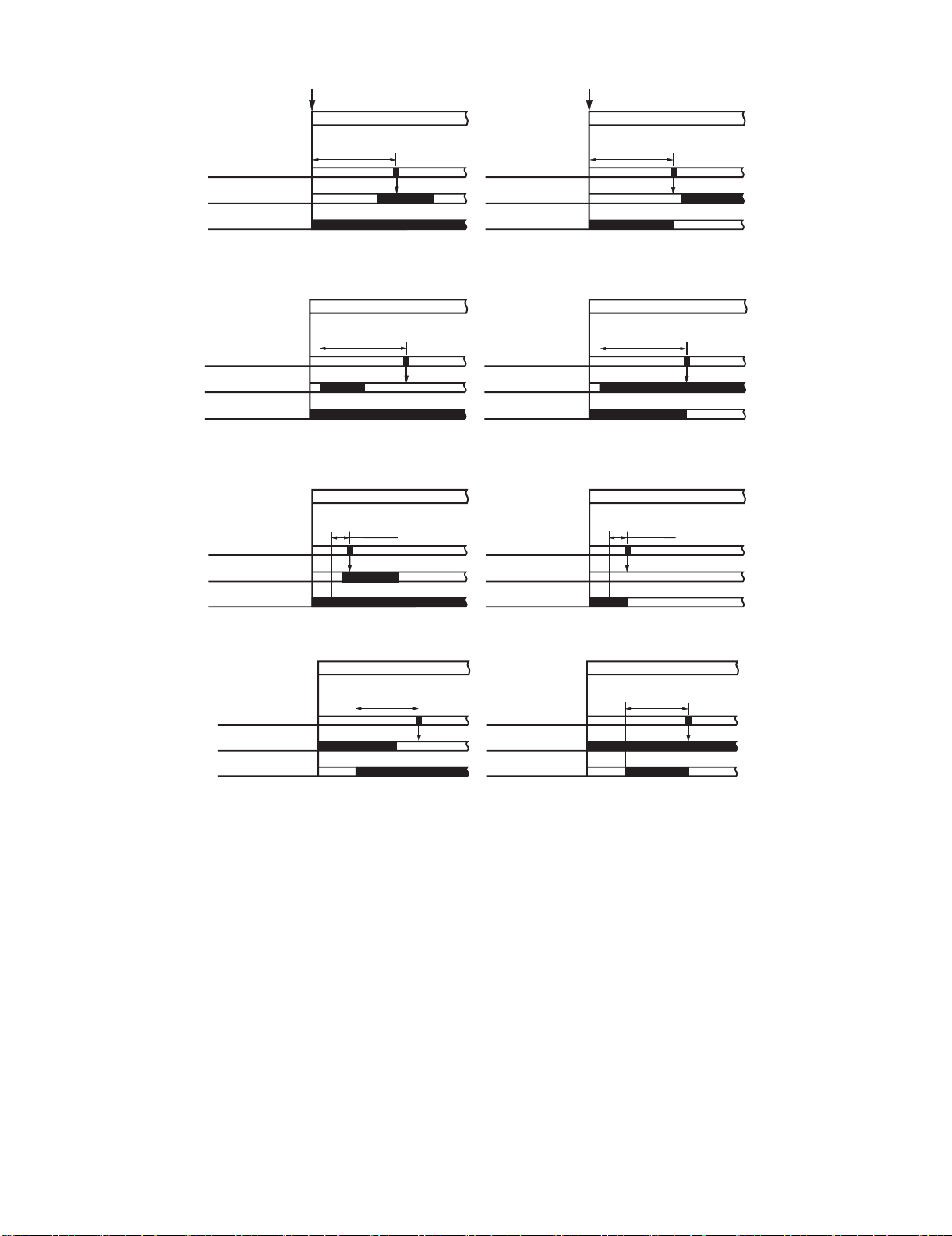
b. Punching Operation
(punch shaft at rest/
home position)
(punch shaft CW rotation by 90°/
punch at upper limit)
(punch shaft CW rotation by 180°/
punch back to initial position)
(punch shaft at rest/
home position)
(punch shaft CCW rotation
by 90°/hole made)
(punch shaft CCW rotation by 180°/
end of punching operation)
The hole puncher is driven by the punch motor (FPNM). The home
position for the hole puncher is detected by the punch home position sensor (FPHPD).
The punch unit comes in four types, selected to suit the country of
installation: 2-hole (Punch Unit-J1), 2- and 3-hole (Punch Unit-K1),
or two types of 4-hole (Punch Unit-G1, Punch Unit-H1).
The 2-hole and 4-hole types punch a hole when the punch shaft is
rotated 180° from the home position, causing the punch to make a
single round trip. The 2-/3-hole type punches a hole, but the circumference of the punch shaft is divided into two (half for 2-hole
and the other half for 3-hole).
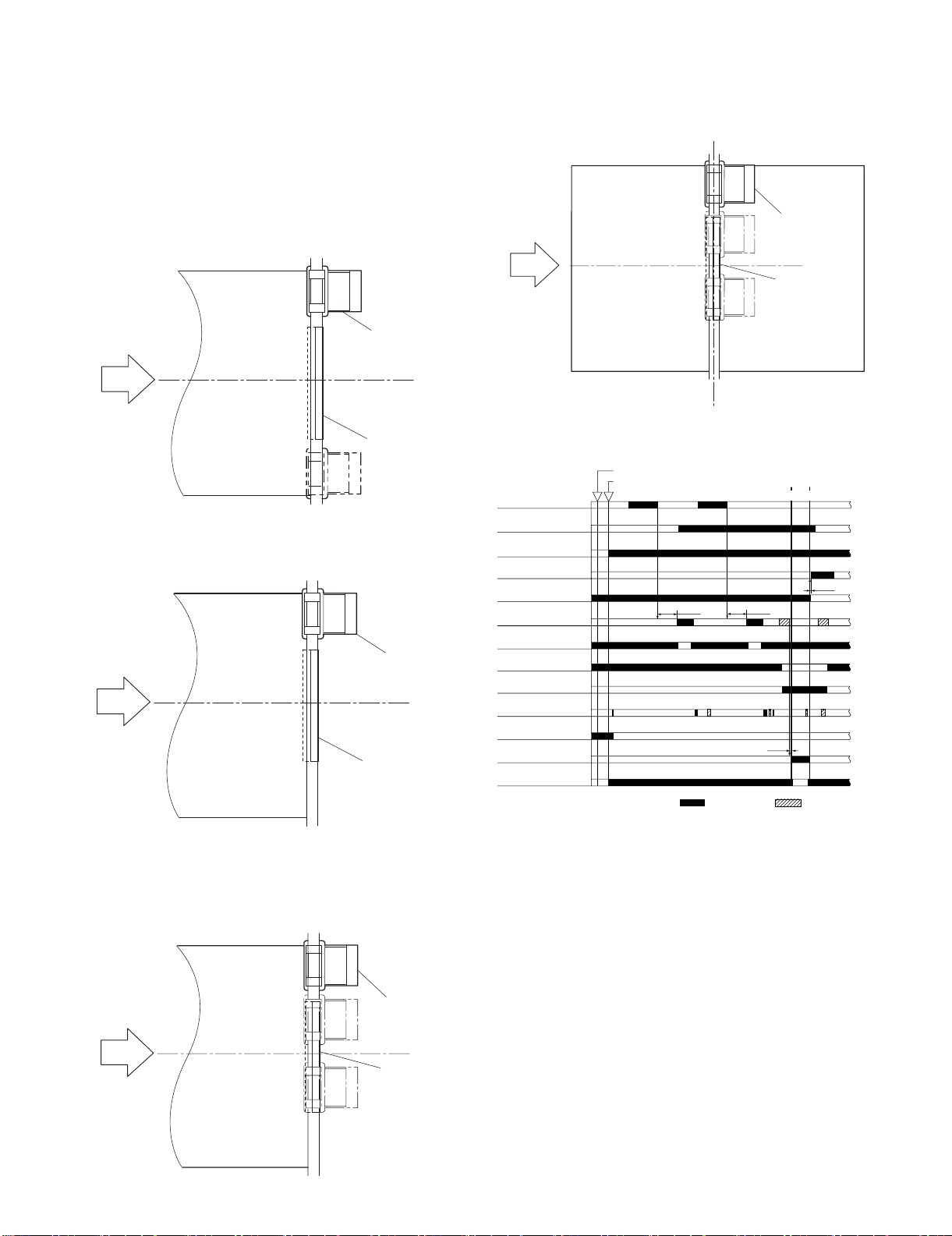
1) 2-Hole, 4-Hole Type
The home position is identified when the punch home position
sensor (FPHPD) is ON. The punching operation for the first
sheet ends when the punch shaft has rotated 180° and the
punch home position sensor (FPHPD) goes ON; the punching
operation for the second sheet ends when the punch shaft has
rotated 180° in reverse and the punch home position sensor
(FPHPD) goes ON.
<1> A hole is punched along the trailing edge of the 1st sheet.
Sensor flag
Punch home position
sensor (FPHPD)
Punch shaft
<1> A hole is made along the trailing edge of the 1st sheet.
Sensor flag
Punch home position
sensor (FPHPD)
Punch shaft
Eccentric cam
(punch shaft at rest/
Die
Die
home position)
Hole
puncher
Paper
(punch shaft CW rotation
by 90°/hole made)
Waste paper
(punch shaft CW rotation by 180°/
end of punching operation)
While two holes are being made, the 3-hole puncher
makes a single round trip in escape direction.
Eccentric cam
Die
Die
(punch shaft at rest/
home position)
Hole
puncher
Paper
(punch shaft CW rotation
by 90°/hole made)
Waste paper
(punch shaft CW rotation by 180°/
end of punching operation)
<2> A hole is made along the trailing edge of the 2nd sheet.
Sensor flag
Punch home position
sensor (FPHPD)
Punch shaft
Eccentric cam
Die
(punch shaft at rest/
Die
home position)
Hole
puncher
Paper
(punch shaft CW rotation
Waste paper
by 90°/hole made)
(punch shaft CW rotation by 180°/
end of punching operation)
2) 2-/3-Hole Type
The home position is identified when the punch home position
sensor (FPHPD) is ON. To make two holes, the punching operation for the first sheet ends when the punch shaft rotates 180°
(half circumference) and the punch home position sensor
(FPHPD) goes ON. At this time, the 3-hole puncher makes a
single round trip in escape direction (moving up the hole
puncher) on a half circumference of the punch shaft. The
punching operation for the second sheet ends when the punch
shaft has rotated 180° counterclockwise and the punch home
position sensor (FPHPD) goes ON (half circumference).
At this time, the 3-hole puncher makes a single round trip in
escape direction (moving up the hole puncher) on the other
half circumference of the punch shaft.
The punching operation takes place as follows when making
two holes in two sheets of paper:
<2> Holes are made along the trailing edge of the 2nd sheet.
While two hole are being made, the 3-hole puncher makes
a single round trip in escape direction (moving up the hole
puncher).
(punch shaft at rest/
home position)
(punch shaft CCW rotation by
90°/punch at upper limit)
(punch CCW rotation by 180°/
punch back at initial position)
MX-FNX2/AR-PN1/MX-RBX1 OPERATIONAL DESCRIPTION 5 – 14
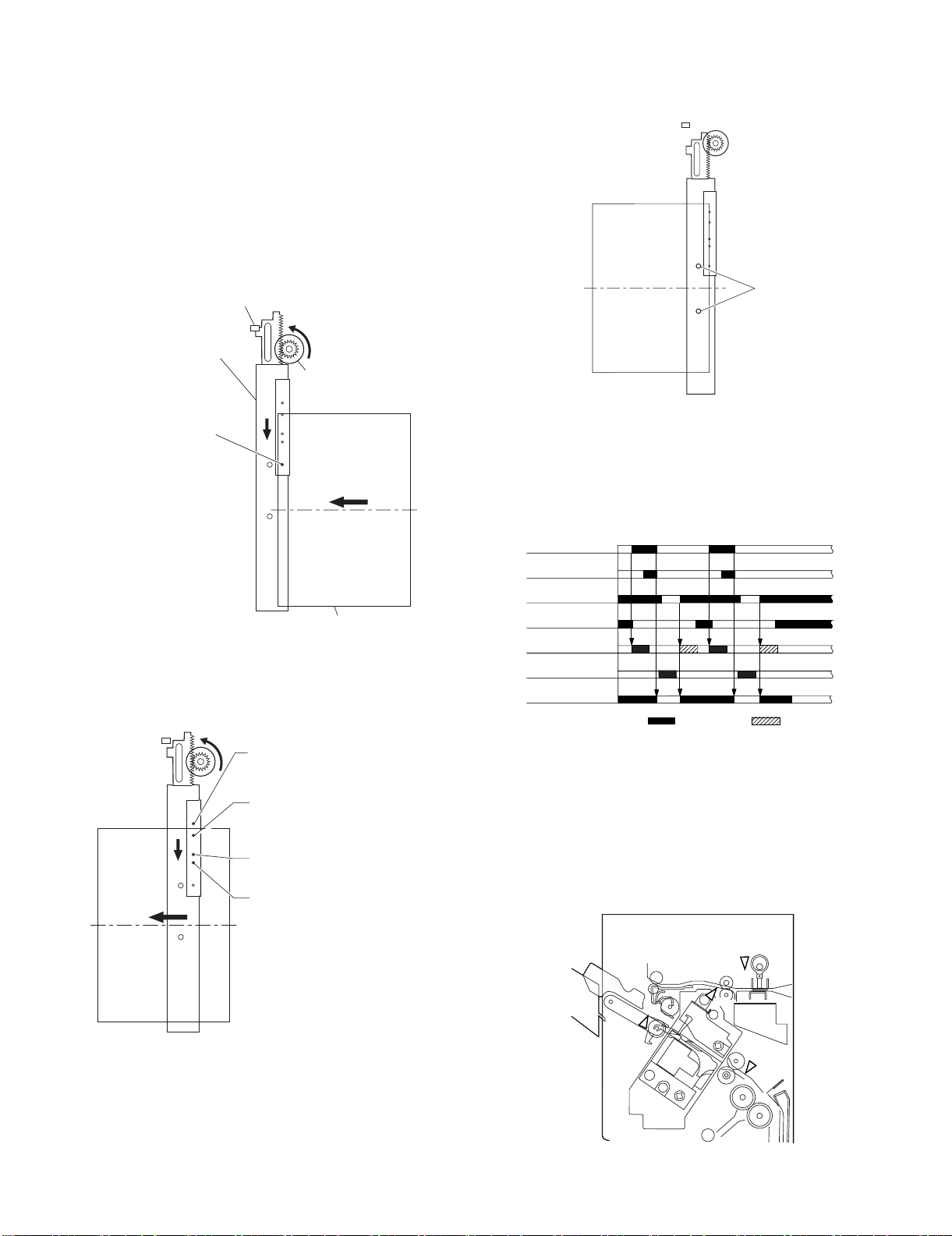
(3) Horizontal Registration Operation
Punch
The horizontal registration drive for the punch slide unit is provided
by the punch horizontal registration motor (FPSM). The home position of the punch slide unit is detected by the punch horizontal registration home position sensor (FPSHPD). The punch slide unit
detects the trailing edge of sheets using the trailing edge sensor
(FPTD) and the horizontal registration sensors (FPSD1 through 4),
and causes a move to a specific position matching the trailing edge
of each sheet (in relation to the size of the sheet).
The horizontal registration operation takes place as follows:
1) When the leading edge of a sheet from the host machine is
detected by the trailing edge sensor (FPTD), the punch horizontal registration motor (FPSM) starts to move the punch
slide unit toward the front.
Punch side resist home position sensor
(FPSHPD)
Punch slide unit
Punch side resist motor
(FPSM)
Trailing edge sensor
(FPTD)
(direction of
paper delivery)
Paper
2) When the horizontal registration sensor (FPSD1 through 4)
suited to the paper size signal from the host machine detects
the rear edge of the sheet, the punch horizontal registration
motor (FPSM) causes a farther move to a specific position,
and stops the punch slide unit.
Horizontal registration sensor 1 (FPSD1);
used to detect the edge of sheets of A3, A4,
8.5" x 11", 11" x 17".
Horizontal registration sensor 2 (FPSD2);
used to detect the edge of sheets of B4, B5,
8.5" x 11"R, 8.5" x 14".
Horizontal registration sensor 3 (FPSD3);
used to detect the edge of sheets of A4R.
Horizontal registration sensor 4 (FPSD4);
used to detect the edge of sheets of B5R.
3) When the trailing edge sensor (FPTD) detects the trailing edge
of the sheet, the drive of the feed motor (FFM) is stopped,
thereby stopping the sheet. Then, the punch motor (FPNM) is
driven to punch holes in the sheet.
4) When the punching operation ends, the feed motor (FFM) of
the fisher unit is driven and, at the same time, the punch horizontal registration motor (FPSM) is rotated in reverse to return
the punch slide unit to its home position.
5) For each sheet that arrives in succession, the punch slide unit
is returned to its home position, and is caused to repeat steps
1 through 4.
Trailing edge sensor
(FPTD)
Horizontal registration
sensor (FPSD1 - 4)
Punch home position
sensor (FPHPD)
Punch horizontal registration
home position sensor (FPSHPD)
Punch horizontal
registration motor (FPSM)
Punch motor (FPNM)
Feed motor (FFM)
: CW rotation : CCW rotation
G. Detecting Jams
(1) Outline
The microprocessor (CPU) on the finisher controller PCB is programmed to check for jams in the finisher/saddle/puncher (option)
at such times as set in advance. It identifies a jam in reference to
the presence/absence of paper at a specific sensor. If a jam is
found, the finisher controller PCB communicates the nature of the
jam to the host machine in the form of a code(which may be
checked in service mode of the host machine).
FAD
FED
: Entry paper sensor
FAD
: Alignment tray sensor
FFPD
: Bookbinding position sensor
FPHPD
: Punch home position sensor
MX-FNX2/AR-PN1/MX-RBX1 OPERATIONAL DESCRIPTION 5 – 15
FPHPD
FED
FFPD
a. Inlet Paper Sensor (FED) Delay Jam
Host machine delivery signal
Host machine delivery signal
Jam check
Entry paper sensor
(FED)
Feed motor (FFM)
approx. 1.0sec.
*
Normal
Jam check
Entry paper sensor
(FED)
Feed motor (FFM)
approx. 1.0sec.
*
Jam
* Variable depending on the paper size. (Because the paper feed speed may differ according to the paper size. (A4:1.0 sec.))
b. Inlet Paper Sensor (FED) Stationary Jam
Jam check
Entry paper sensor
(FED)
Feed motor (FFM)
approx. 1.4sec.*
Normal
Jam check
Entry paper sensor
(FED)
Feed motor (FFM)
approx. 1.4sec.*
Jam
* Variable depending on the paper size. (Because the paper feed speed may differ according to the paper size. (A4:1.4 sec.))
c. Binding Position Sensor (FFPD) Delay Jam
Jam check
Binding position
sensor (FFPD)
Stack delivery motor
(FAM)
1080 ms
Normal
Jam check
Binding position
sensor (FFPD)
Stack delivery motor
(FAM)
1080 ms
Jam
d. Binding Position Sensor (FFPD) Stationary Jam
Jam check
Binding position
sensor (FFPD)
Staple motor (FFSM)
approx. 16.2sec. approx.16.2sec.
Normal
Jam check
Binding position
sensor (FFPD)
Staple motor (FFSM)
Jam
e. Power-On Jam
Paper is detected inside the finisher at power-on or when the door is closed.
f. Door Open Jam
The finisher is disconnected from its host machine or the front door, or the upper cover is opened while the system is in operation (paper on the
move).
g. Staple Jam
The staple drive home position sensor (FSHPD) does not go OFF 600 msec after the stapler is driven. Or, it does not return to its home position
(where the sensor goes ON).
MX-FNX2/AR-PN1/MX-RBX1 OPERATIONAL DESCRIPTION 5 – 16
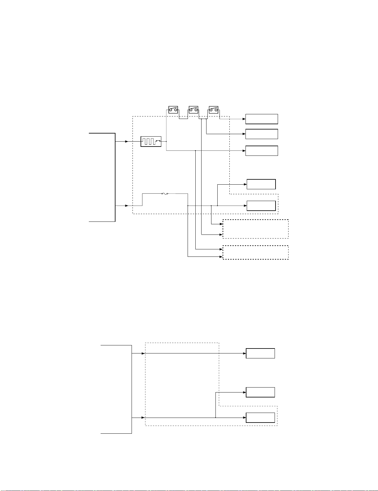
H. Power Supply System
(1) Finisher/Saddle Assembly
a. Outline
When the host machine is turned on, it supplies the finisher controller PCB with 24VDC and 5VDC. 24VDC is for the motors and clutches.
24VDC and 5VDC are also supplied as a relay pass drive, 5VDC is used to drive sensors and ICs on PCBs.
If a punch unit (option) is installed, power is also supplied to the punch controller PCB.
Some of 24 VDC used to drive motors is cut off when the joint switch (FJSW), front door switch (FFDDW), or stapler safety switch (FSSSW) is
open.
The block diagram of the power supply system is below.
Front door switch
Joint switch
(FJSW)
(FFDDW)
Stapler safety switch
(FSSSW)
24V
Motor
Host
machine
24VC
5VDC
Circuit Breaker
(CB1)
Finisher
controller PCB
Circuit protector
24V
24V
(CP2)
Punch controller PCB
(punch unit; option)
Relay interface PCB
5V
5V
Logic system
Motor
Clutch
Sensor
b. Protective Mechanisms
A circuit breaker (CB1) is monitored to protect the 24 VDC system used to drive the motors against overcurrent. The 24-V system used to drive
the feed motor (FFM), paddle motor (FPM), and stack delivery motor (FAM) is equipped with a fuse which melts in the presence of overcurrent.
(2) Punch Unit (option)
a. Outline
When the host machine is turned on, the punch unit is supplied by the finisher controller PCB with 24-V and 5-V power.
The 24-V power is used to drive the motors, while the 5-V power is used by sensors and the ICs on the punch controller PCB.
The 24-V power to the motors will be cut off when the joint switch (FJSW) or the front door switch (FFDDW) of the finisher unit is open.
The following is a block diagram for the power supply system:
Finisher
controller
PCB
24 V
Punch controller PCB
5V
24 V
5V
5V
Motors
Sensors
Logic system
b. Protective Mechanisms
The 24-V system used to drive the punch motor (FPNM) and the punch horizontal registration motor (FPSM) is equipped with a built-in fuse
which melts in the presence of overcurrent.
MX-FNX2/AR-PN1/MX-RBX1 OPERATIONAL DESCRIPTION 5 – 17

âºíuÇ´
[6] DISASSEMBLY AND
ASSEMBLY
1) Turn off the host machine, disconnect the saddle stitch finisher
connctor.
2) Free the lock, and remove the saddle stitch finisher from the
host machine.
1. Saddle stitch finiser (MX-FNX2)
A. Externals and Controls
(1) Delivery tray
1) Remove the delivery tray.
2) Remove the front cover.
Service Manual
(3) Rear Cover
1) Remove the rear cover.
(2) Front Cover
1) Open the front door, and remove the knob.
1
2
(4) Upper Cover
1) Remove the front cover. (See (2).)
2) Remove the rear cover. (See (3).)
3) Open the upper cover, and remove the cover band.
2
1
4) Detach the processing cover, and remove the upper cover.
2
1
MX-FNX2/AR-PN1/MX-RBX1 DISASSEMBLY AND ASSEMBLY 6 – 1
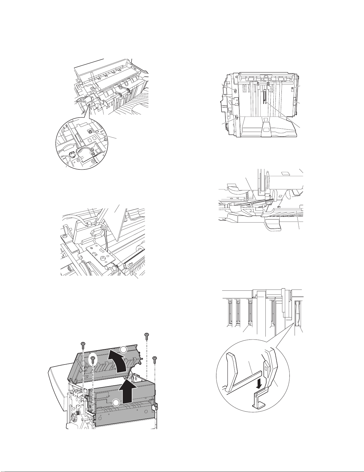
(5) Processing Tray Upper Cover
[6]
[5]
[5]
[6]
1) Remove the front cover. (See (2).)
2) Remove the rear cover. (See (3).)
3) Remove the upper cover. (See (4).)
4) Disconnect the connector [1] and remove the screw [2].
(7) Removing the Saddle Guide
1) Remove the delivery tray. (See (1).)
2) Remove the front cover. (See (2).)
3) Remove the rear cover. (See (3).)
4) Free the delivery tray support plate (front) [1] and the delivery
tray support plate (rear) [2] to the outside from the rail grooves.
5) Remove the four screws [3].
[2]
[1]
5) While lifting the processing tray cover [3], disconnect the connector [4], then remove the processing tray upper cover [3].
[3]
[4]
[3]
[3]
[2]
[1]
[3]
6) Shift the side guide [4] lightly to the front, and free the engagement of the paper surface detecting lever (rear) [5]; then,
detach the side guide [4].
[3]
[5]
[4]
NOTE: Be sure to mount the side guide after securely fitting the
paper surface detecting lever (rear) [5] in the groove of the
paper surface detecting lever (middle) [6].
After completion of mounting, push the paper surface
detecting lever several times to make sure that side guide
is mounted securely.
(6) Upper Right Cover, Middle Right Cover
1) Remove the front cover. (See (2).)
2) Remove the rear cover. (See (3).)
3) Open the upper cover, then remove the upper right cover and
the middle right cover.
1
2
MX-FNX2/AR-PN1/MX-RBX1 DISASSEMBLY AND ASSEMBLY 6 – 2

B. Feeding System
[2]
[5]
[3]
[4]
[1]
[14]
[15]
[13]
(1) Removing the Stapler Unit
1) Open the front door.
2) Slide out the stapler unit while pressing the stopper.
1
3
2
NOTE: Do not remove the stapler stapler frame shaft. If removed,
the position where the staple driver (lower unit of the stapler) [4] shoots stables will shift from the position where the
staple clincher (upper unit of the stapler) [5] receives staples.
[5]
[4]
1) Detach the gear cover [2] from the staple driver [1].
2) Remove the E-ring [3] to detach the side cover [5] of the staple
clincher [4].
3) Remove the two E-rings [6] to remove the staple jam releasing
gear [7], timing belt [8], and relay gear 1 [9]. Remove the
spacer and spring at the back of the staple jam releasing gear.
4) Remove the screw [10] and spring [11] to remove the belt tensioner [12].
[7]
[8]
[6]
[11]
[9]
[10]
(2) Adjusting the Stapler Phase
When the gears or timing belt at the front of the stapler is replaced
or removed for some reason, the staple shooting timing of the
(lower unit of the stapler) does not match the staple bending timing
of the staple clincher (upper unit of the stapler). Adjust the stapler
phase following the procedure described below.
Gear
Timing belt
Gear
[12]
5) Remove the timing belt [13].
6) Remove the E-ring [14] to remove the staple position check
gear [15].
7) Turn the gear [16] to align the round hole in the staple driver
gear with the round hole [17] at the back.
[16]
[17]
MX-FNX2/AR-PN1/MX-RBX1 DISASSEMBLY AND ASSEMBLY 6 – 3
Loading...