


 Loading...
SERVICE MANUAL
CODE: 00ZMXFNX1/S1E
DIGITAL FULL COLOR MULTIFUNCTIONAL SYSTEM OPTION
 FINISHER / PUNCH MODULE
MX-FNX1
MODEL MX-PNX1A/B/C/D
CONTENTS
[1] PRODUCT OUTLINE . . . . . . . . . . . . . . . . . . . . . . . . . . . . . . . . . . . 1-1 [2] SPECIFICTIONS . . . . . . . . . . . . . . . . . . . . . . . . . . . . . . . . . . . . . . . 2-1
[3]UNPACKING AND INSTALLATION
*For how to unpacking and installation, refer to the installation manual (00ZMX2700/I1E).
[4] EXTERNAL VIEW AND INTERNAL STRUCTURE . . . . . . . . . . . . . 4-1 [5] OPERATIONAL DESCRIPTIONS . . . . . . . . . . . . . . . . . . . . . . . . . . 5-1
[6] DISASSEMBLY AND ASSEMBLY. . . . . . . . . . . . . . . . . . . . . . . . . . 6-1 [7] MAINTENANCE. . . . . . . . . . . . . . . . . . . . . . . . . . . . . . . . . . . . . . . . 7-1
[8] ADJUSTMENTS . . . . . . . . . . . . . . . . . . . . . . . . . . . . . . . . . . . . . . . 8-1
[9] SELF DIAGNOSTICS AND TROUBLE CODES . . . . . . . . . . . . . . . 9-1 [10] ELECTRICAL SECTION . . . . . . . . . . . . . . . . . . . . . . . . . . . . . . . . 10-1
PARTS GUIDE
Parts marked with "  " are important for maintaining the safety of the set. Be sure to replace these parts with specified ones for maintaining the safety and performance of the set.
This document has been published to be used SHARP CORPORATION for after sales service only.
The contents are subject to change without notice.
CONTENTS
[1] |
PRODUCT OUTLINE. . . . . . . . . . . . . . . . . . . |
1-1 |
[6] |
DISASSEMBLY AND ASSEMBLY |
|
||
[2] |
SPECIFICTIONS |
|
|
1. |
MX-FNX1 . . . . . . . . . . . . . . . . . . . . . . |
. . 6-1 |
|
|
|
2. |
MX-PNX1A/B/C/D |
6-11 |
|||
|
1. |
MX-FNX1 |
2-1 |
|
|||
|
|
|
|
|
|||
|
2. |
MX-PNX1A/B/C/D . . . . . . . . . . . . . . . . . . |
2-1 |
[7] |
MAINTENANCE |
|
|
[3] |
UNPACKING AND INSTALLATION |
|
|
1. |
Maintenance system table . . . . . . . . . . |
. 7-1 |
|
|
|
|
|
|
|||
|
* For how to unpacking and installation, refer to the |
|
[8] |
ADJUSTMENTS |
|
||
|
|
installation manual (00ZMX2700/I1E). |
|
|
1. |
Setting item list |
8-1 |
|
|
|
|
|
|||
[4] EXTERNAL VIEW AND INTERNAL |
|
|
2. |
Details . . . . . . . . . . . . . . . . . . . . . . . . . . |
. 8-1 |
||
|
STRUCTURE |
|
[9] |
SELF DIAGNOSTICS AND TROUBLE CODES |
|||
|
1. |
Identification of each section and |
|
||||
|
|
functions . . . . . . . . . . . . . . . . . . . . . . . . . . |
4-1 |
|
1. |
Trouble code and troubleshooting. . . . . |
. 9-1 |
[5] |
OPERATIONAL DESCRIPTIONS |
|
[10] |
ELECTRICAL SECTION |
|
||
|
1. |
Electrical mechanism diagram . . . . . . . . . |
5-1 |
|
1. |
Circuit descriptions . . . . . . . . . . . . . . . . |
10-1 |
|
2. |
General. . . . . . . . . . . . . . . . . . . . . . . . . . . |
5-5 |
|
2. |
Block diagram . . . . . . . . . . . . . . . . . . . |
10-12 |
|
3. |
Outline of the transport path . . . . . . . . . . . |
5-5 |
|
3. |
Actual wiring diagram . . . . . . . . . . . . . |
10-14 |
|
4. |
Non-sort mode . . . . . . . . . . . . . . . . . . . . . |
5-6 |
|
PARTS GUIDE |
|
|
|
5. |
Offset mode |
5-6 |
|
|||
|
|
|
|
|
|||
|
6. |
Staple mode . . . . . . . . . . . . . . . . . . . . . . . |
5-7 |
|
|
|
|
|
7. |
Punching process. . . . . . . . . . . . . . . . . . . |
5-9 |
|
|
|
|

[1] PRODUCT OUTLINE
This unit is used by installing to the main unit for after-process of copy and FAX output paper. It is provided with the offset function which discharges output paper by shifting one by one.
Since it is installed to the center tray section of the main unit, no extra space for installation is required.
1)3 kinds of auto staple functions: There are 3 kinds of stapling positions. (One position in front, one position backward, 2 positions at the center).
2)Punch function (option): By installing the punch unit, paper can be punched to make binder holes. (Paper of 64 to 128g/m2 can be used. OHP film cannot be used.)
Models enable to install the unit |
MX-2300G/2700G/2300N/2700N |
The finisher requires a staple cartridge as a consumable part. (Staple cartridge (about 5,000 staples x 3 pcs.) MX-SCX1)
Staple cartridge (Approx. 5000 x 3) (MX-SCX1)
Finisher
(MX-FNX1)
Punch module
●2-hole (MX-PNX1A)
●3-hole (MX-PNX1B)
●4-hole (MX-PNX1C)
●4-hole (broad space) (MX-PNX1D)
Paper pass unit (MX-RBX1)
Staple cartridge (Approx. 5000 x 3) (AR-SC2)
Device Tray with |
|
|
USB Hub (MX-RKX1) |
Reversing single pass feeder |
|
|
|
(MX-RPX1) |
PCL5c/PCL6 |
Network |
SPLC-c |
driver |
scanner |
driver |
|
(Sharpdesk 1 license) |
|
|
|
Document cover |
RSPF |
|
(MX-VRX1) |
HDD |
HDD |
Exit tray unit |
|
||
|
|
(MX-TRX1) |
Copier/Printer (PCL) |
Copier/Printer (SPLC-c) |
|
/Scanner model |
model |
|
(MX-2300N) (MX-2300G) (MX-2700N) (MX-2700G)
Punch module |
|
|
|
|
|
|
|
|
|
● 2-hole (AR-PN1A) |
|
|
|
|
|
|
|
|
|
● 3-hole (AR-PN1B) |
Saddle stitch finisher |
Stand/1x500 sheet |
Stand/2x500 sheet |
Large capacity tray |
|||||
● 4-hole (AR-PN1C) |
|||||||||
(MX-FNX2) |
|
paper drawer |
paper drawer |
|
(MX-LCX1) |
||||
● 4-hole (broad space) |
|
|
|||||||
(AR-PN1D) |
|
|
(MX-DEX1) |
|
(MX-DEX2) |
|
|
||
|
|
|
|
|
|
|
|
||
|
Barcode font kit |
Printer expansion |
Network scanner |
PS3 expansion |
|
Facsimile |
|||
|
kit (PCL) |
expansion kit |
kit |
|
|
||||
|
|
|
|
|
|||||
|
|
|
|
|
|
|
|
expansion kit |
|
|
|
|
|
|
|
|
|
(MX-FXX1) |
|
|
CD |
ROM |
|
|
|
|
|
|
|
|
(AR-PF1) |
CD |
CD |
CD |
ROM |
|
|
||
|
(MX-PBX1) |
(MX-NSX1) |
|
|
|
FAX memory (8MB) |
|||
|
|
|
|
|
|
||||
Data security kit |
|
(For MX-2300G/2700G) |
(MX-PKX1) |
|
(packed together) |
||||
|
|
|
|||||||
(Including document control) |
|
|
|
|
|
|
|
||
CC authentication |
Commercial |
|
Internet Fax |
Sharpdesk |
Sharpdesk |
|
|
||
version |
version |
|
expansion kit |
1 license kit |
10 license kit |
|
|
||
|
|
|
|
Sharpdesk |
Sharpdesk |
|
|
||
|
|
|
|
5 license kit |
50 license kit |
|
|
||
Security |
Security |
|
|
|
|
|
|
||
ROM |
ROM |
|
|
|
|
|
|
|
|
|
|
|
CD |
CD |
|
CD |
|
|
|
|
|
|
|
(MX-USX1/ |
(MX-US10/ |
|
|
||
|
|
|
(MX-FWX1) |
USX5) |
|
US50) |
|
|
|
For document |
For document |
|
Sharpdesk |
|
|
|
|
||
control PWB |
control PWB |
Application |
Application |
External |
|
||||
(MX-FRX1) |
(MX-FRX1U) |
integration |
100 license kit |
communication |
account module |
||||
module |
|
module |
|
|
|||||
|
|
|
|
|
|
||||
256MB expansion memory board |
|
|
|
|
(MX-SMX1) |
|
|
|
|
|
CD |
CD |
CD |
CD |
(For MX-2300G/2700G) |
(MX-AMX1) |
(MX-USA0) |
(MX-AMX2) |
(MX-AMX3) |
MX-FNX1/MX-PNX1 PRODUCT OUTLINE 1 – 1
[2] SPECIFICTIONS
1. MX-FNX1
Type |
Inner finisher |
|
Loading method |
Offset tray |
|
Transport speed |
23, 27, 35, 45 PPM |
|
Tray type |
Offset tray |
|
Transport reference |
Center reference |
|
Paper exit direction |
Face down |
|
Paper weight |
Plain paper: |
60 to 105g/m2 (16 to 28 lbs) |
|
Thin paper: |
55 to 59g/m2 (15 to 16 lbs) |
|
Heavy paper: |
106 to 209g/m2 (28 to 56 lbs) |
|
Special paper: |
OHP sheet, label sheet, envelopes, tab paper: Limited to non-sort (up to 10 sheets). |
Mode type |
Non-stapled, stapled |
|
Paper sizes allowed for offset |
A3, B4, A4, A4R, B5, 8K, 16K, 11" x 17", 8.5" x 14", 8.5" x 13", 8.5" x 11", 8.5" x 11"R |
|
Offset quantity |
30mm, 1.2 inch |
|
Discharged paper size |
A3, B4, A4, A4R, A5R, B5, B5R, 8K, 16K, 16KR, 12" x 18", 11" x 17", 8.5" x 14", 8.5" x 13", 8.5" x 11", 8.5" x 11"R, |
|
|
5.5" x 8.5"R, 7.25" x 10.5"R, A3 wide, special paper |
|
Sortable size |
Metric series |
Large size: A3, B4, 8K |
|
|
Small size: A4, A4R, B5, 16K |
|
Inch series |
Large size: 11" x 17", 8.5" x 14", 8.5" x 13" |
|
|
Small size: 8.5" x 11", 8.5" x 11"R |
Stack tray max. load capacity |
Large size: |
Max. 250 sheets or max. 30 sets or 35.5mm |
|
Small size: |
Max. 500 sheets (For special paper, max. 10 sheets can be loaded on the tray.) or max. 30 sets or 71mm |
Staplable paper weight |
60 to 128g/m2 (16 to 34 lbs) * However, "106 to 128g/m2 (28 to 34 lbs)" is enable only for two sheets. |
|
Staplable paper size |
A3, B4, A4, A4R, B5, 8K, 16K, 16KR, 11" x 17", 8.5" x 14", 8.5" x 13", 8.5" x 11", 8.5" x 11"R |
|
Staplable paper quantity (Max.) |
Max. 50 sheets (for small size, 90g/m2 (24 lbs)) |
|
|
Max. 30 sheets (for large size, 90g/m2 (24 lbs)) |
|
Stapling |
3 kinds (One position in front, one position backward, 2 positions). |
|
Staple supply system |
Staple sheet cartridge replacement system (Staple cartridge (Approx. 5,000 x 3 pcs.) MX-SCX1) |
|
Staple detection |
Staple empty detection (Near empty detection: 20 staples remained) |
|
Manual stapling |
No |
|
External dimensions (W x D x H) |
440 x 595 x 205 (mm), 17 21/64 x 23 27/64 x 8 5/64 (inch) |
|
|
(with tray extended: 640 x 595 x 205 (mm), 25 12/64 x 23 27/64 x 8 5/64 (inch)) |
|
Weight |
Approx. 13kg (28.7 lbs) |
|
Power source |
Supplied from the main unit power source. (DC24V, DC5V) |
|
Power consumption |
55.2W |
|
Installation/maintenance |
Installed by service personnel |
|
Optional detection |
Auto detection supported |
|
Packaged items |
Parts for mounting, operational sheet, staple directional instruction label, installation cautionary note |
|
2. MX-PNX1A/B/C/D
Type |
Punch unit for the inner finisher |
||
Punch type |
2 holes / 3 holes / 4 holes / 4 holes (wide) |
||
|
A punch unit that provides all of these 4 types can be installed. |
||
Transport speed |
23, 27, 35, 45 PPM |
||
Transport reference |
Center reference |
|
|
Punch dust full detection |
YES (Lever system) |
||
Paper exit direction |
Face down |
|
|
Paper weight |
Plain paper: |
60 to 105g/m2 (16 to 28 lbs) |
|
|
Thin paper: |
55 to 59g/m2 (15 to 16 lbs) |
|
|
Heavy paper: |
106 to 209g/m2 (28 to 56 lbs) |
|
Punchable paper size |
2 holes |
|
A3, B4, A4, A4R, B5, B5R, 11" x 17", 8.5" x 14", 8.5" x 13", 8.5" x 11", 8.5" x 11"R, 8K, 16K, 16KR |
|
(MX-PNX1A) |
|
|
|
3 holes *1 |
|
3 holes: A3, A4, 11" x 17", 8.5" x 11" |
|
(MX-PNX1B) |
|
2 holes: 8.5" x 14", 8.5" x 13", 8.5" x 11"R |
|
4 holes |
|
A3, A4 |
|
(MX-PNX1C) |
|
|
|
4 holes (wide) |
|
A3, B4, A4, A4R, B5, B5R, 11" x 17", 8.5" x 14", 8.5" x 13", 8.5" x 11", 8.5" x 11"R |
|
(MX-PNX1D) |
|
|
Power source |
Supplied from the inner finisher. (DC24V, DC5V) |
||
External dimensions (W x D x H) |
105 x 518 x 170 (mm), 4 9/64 x 20 25/64 x 6 45/64 (inch) |
||
Weight |
Approx. 3.5kg (7.7 lbs) |
||
Packaged items |
Parts for mounting, instructional label for punch direction, instructional label for garbage pickup, installation cautionary note |
||
*1: Auto switching: 2 holes/3 holes
MX-FNX1/MX-PNX1 SPECIFICTIONS 2 – 1
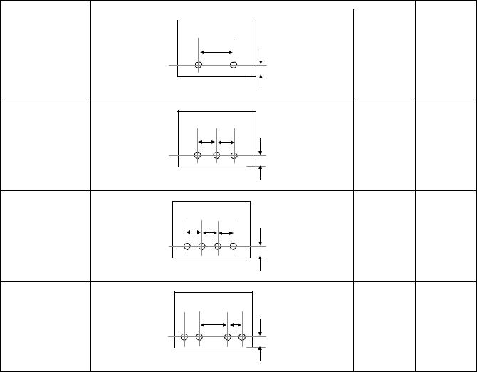
Kind of hole punch
Kind |
Hole position |
Hole size |
|
2 holes (MX-PNX1A) |
|
A: 80±1mm |
φ6.5mm |
|
|
B: 12±3mm |
|
A |
|
|
|
B |
|
3 holes (MX-PNX1B) |
A: 108±1mm |
φ8.0mm |
|
B: 12±3mm |
|
A |
A |
|
|
B |
|
4 holes (MX-PNX1C) |
A: 80±1mm |
φ6.5mm |
|
B: 12±3mm |
|
A A |
A |
|
|
B |
|
4 holes (wide) (MX-PNX1D) |
A: 70±1mm |
φ6.5mm |
|
B: 12±3mm |
|
|
C: 21±1mm |
|
A |
C |
|
|
B |
|
MX-FNX1/MX-PNX1 SPECIFICTIONS 2 – 2
[4] EXTERNAL VIEW AND INTERNAL STRUCTURE
1. Identification of each section and functions
A. Internal structure
1
2 |
5 |
|
|
3 |
6 |
4 |
7 |
No. |
Name |
1 |
Paper exit roller |
2 |
Bundle exit paper transport roller |
3 |
Paper exit roller |
4 |
Bundle exit paper transport roller |
5 |
Inlet port paper transport roller |
6 |
Inlet port paper transport roller |
7 |
Take-up belt |
B. Sensors and switches
(1) |
MX-FNX1 |
|
|
1 |
|
|
2 |
|
|
3 |
|
|
4 |
11 |
|
12 |
10 |
|
5 |
|
|
|
|
|
13 |
6 |
|
15 |
|
|
|
|
|
14 |
16,17,18 |
|
8 |
|
|
|
|
|
7 |
9 |
|
|
|
|
|
MX-FNX1/MX-PNX1 EXTERNAL VIEW AND INTERNAL STRUCTURE 4 – 1 |
No. |
Signal |
Name |
Type |
Function/Operation |
Output |
1 |
FULD |
Tray upper limit sensor |
Photo interrupter |
Detects the upper limit position of the |
TP1 is driven to “L” at the upper limit |
|
|
|
|
paper load tray up/down shift area. |
position. |
2 |
FMLLD |
Tray intermediate lower limit |
Photo interrupter |
Detects the intermediate position of the |
TP2 is driven to “L” at the intermediate |
|
|
sensor |
|
paper load tray up/down shift area. |
position. |
3 |
FLLD |
Tray lower limit sensor |
Photo interrupter |
Detects the lower limit position of the |
TP3 is driven to “L” at the lower limit |
|
|
|
|
paper load tray up/down shift area. |
position. |
4 |
FBED |
Tray paper empty sensor |
Photo interrupter |
Detects paper empty in the paper load |
TP4 is driven to “L” when paper is |
|
|
|
|
tray. |
provided. |
5 |
FSLD1 |
Paper surface sensor 1 |
Photo interrupter |
Detects the surface position of paper on |
*Refer to the separate table outside the |
6 |
FSLD2 |
Paper surface sensor 2 |
Photo interrupter |
the tray in combination of the both sensors |
column. |
|
|
|
|
outputs. |
|
7 |
FSTHPD |
Stapler HP sensor |
Photo interrupter |
Detects the home position of the stapler |
TP7 is driven to “H” at the home position. |
|
|
|
|
unit in F/R direction shift. |
|
8 |
FSTPD |
Empty sensor |
Photo interrupter |
Detects paper empty on the process tray. |
TP8 is driven to “H” when paper is |
|
|
|
|
|
provided. |
9 |
FFJHPD |
Alignment plate HP sensor F |
Photo interrupter |
Detects the home position of the alignment |
TP9 is driven to “L” at the home position. |
|
|
|
|
guide on F side. |
|
10 |
FRJHPD |
Alignment plate HP sensor R |
Photo interrupter |
Detects the home position of the alignment |
TP10 is driven to “L” at the home position. |
|
|
|
|
guide on R side. |
|
11 |
FED |
Inlet port sensor |
Photo interrupter |
Detects paper in the inlet port of the |
TP11 is driven to “H” when paper is |
|
|
|
|
finisher. |
provided. |
12 |
FRLD |
Roller up/down sensor |
Photo interrupter |
Detects the upper standby position of up/ |
TP12 is driven to “L” when the roller |
|
|
|
|
down movement of the bundle exit roller. |
reaches the upper standby position. |
13 |
FBRD |
Take-up belt sensor |
Photo interrupter |
Detects up/down positions of the take-up |
TP13 is driven to “L” when the take-up belt |
|
|
|
|
belt. |
is on the upper side. |
14 |
FDSW |
Front cover switch |
Photo interrupter |
Detects open/close of the jam release |
TP15 is driven to “L” when the cover is |
|
|
|
|
cover in the front section. |
closed. |
15 |
FJPD |
Alignment plate position sensor |
Photo interrupter |
Detects entry of the process section rear |
TP50 is driven to “L” when the stopper |
|
|
|
|
edge stopper into the opening of the |
enters the opening of the stapler. |
|
|
|
|
stapler and inhibits stapling. |
|
16 |
FSHPD |
Stapler home sensor |
|
Detects the home position of the stapling |
TP51 is driven to “H” at the home |
|
|
|
|
mechanism. (Sensor built in the stapler |
(standby) position. |
|
|
|
|
unit) |
|
17 |
FSD |
Staple empty sensor |
|
Detects staple empty. (Sensor built in the |
TP53 is driven to “L” when staple empty. |
|
|
|
|
stapler unit) |
|
18 |
FSTD |
Self priming sensor |
|
Detects the staple feed is completed and it |
TP52 is driven to “H” when in the ready |
|
|
|
|
is ready for stapling. (Sensor built in the |
state. |
|
|
|
|
stapler unit) |
|
FSLD1 |
FSLD2 |
State |
|
TP5 |
TP6 |
||
|
|||
“L” |
“H” |
The paper detection lever is in the save position. |
|
“H” |
“H” |
The paper surface is upper than the reference level. |
|
“H” |
“L” |
The paper surface is at the reference level. |
|
“L” |
“L” |
The paper surface is lower than the reference level. |
MX-FNX1/MX-PNX1 EXTERNAL VIEW AND INTERNAL STRUCTURE 4 – 2
(2)MX-PNX1A/B/C/D
|
3 |
|
2 |
11 |
|
10 |
||
|
9
8
7
6
4
5 |
1 |
No. |
Signal |
Name |
Type |
Function/Operation |
Output |
1 |
FPDD |
Full sensor |
Photo interrupter |
Detects full of the punch dust container. |
When full, TP2 on the punch PWB remains |
|
|
|
|
|
“H” level. |
2 |
FPHPD |
Punch position |
Photo interrupter |
Detects the home position of the punch up/down |
TP47 on the control PWB of the inner finisher |
|
|
sensor |
|
shift. |
is driven to “H” at the home position. |
3 |
FPRPD |
Rear position |
Photo interrupter |
Detects the lower limit position of 3-hole side up/ |
TP48 on the control PWB of the inner finisher |
|
|
sensor |
|
down shift in 2/3-hole punching. |
is driven to “H” at the lower limit position. |
4 |
FPSHPD |
Horizontal shift |
Photo interrupter |
Detects the home position in the punch position |
TP49 on the control PWB of the inner finisher |
|
|
HP sensor |
|
horizontal resist correction mechanism. |
is driven to “H” at the home position. |
5 |
FPPEND |
Paper rear edge |
Transmission type |
Detects the lead edge and the rear edge of paper |
TP54 on the control PWB of the inner finisher |
|
|
sensor |
sensor |
to be punched. |
is driven to “L” when paper is provided. |
6 |
FPPD1 |
Paper horizontal |
Transmission type |
Detects the paper edge in the rear side of B5R or |
TP55 on the control PWB of the inner finisher |
|
|
resist sensor 1 |
sensor |
7.25" x 10" R size width direction of the machine. |
is driven to “L” when paper is provided. |
7 |
FPPD2 |
Paper horizontal |
Transmission type |
Detects the paper edge in the rear side of 16K-R |
TP55 on the control PWB of the inner finisher |
|
|
resist sensor 2 |
sensor |
size width direction of the machine. |
is driven to “L” when paper is provided. |
8 |
FPPD3 |
Paper horizontal |
Transmission type |
Detects the paper edge in the rear side of 8.5" |
TP55 on the control PWB of the inner finisher |
|
|
resist sensor 3 |
sensor |
x14", 8.5" x 11"R, 8.5" x 13", or A4R size width |
is driven to “L” when paper is provided. |
|
|
|
|
direction of the machine. |
|
9 |
FPPD4 |
Paper horizontal |
Transmission type |
Detects the paper edge in the rear side of B4 or |
TP55 on the control PWB of the inner finisher |
|
|
resist sensor 4 |
sensor |
B5 size width direction of the machine. |
is driven to “L” when paper is provided. |
10 |
FPPD5 |
Paper horizontal |
Transmission type |
Detects the paper edge in the rear side of 11" x |
TP55 on the control PWB of the inner finisher |
|
|
resist sensor 5 |
sensor |
17", 8.5" x 11", 8K, or 16K size width direction of |
is driven to “L” when paper is provided. |
|
|
|
|
the machine. |
|
11 |
FPPD6 |
Paper horizontal |
Transmission type |
Detects the paper edge in the rear side of A3 or |
TP55 on the control PWB of the inner finisher |
|
|
resist sensor 6 |
sensor |
A4 size width direction of the machine. |
is driven to “L” when paper is provided. |
MX-FNX1/MX-PNX1 EXTERNAL VIEW AND INTERNAL STRUCTURE 4 – 3
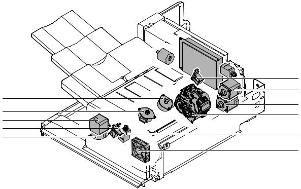
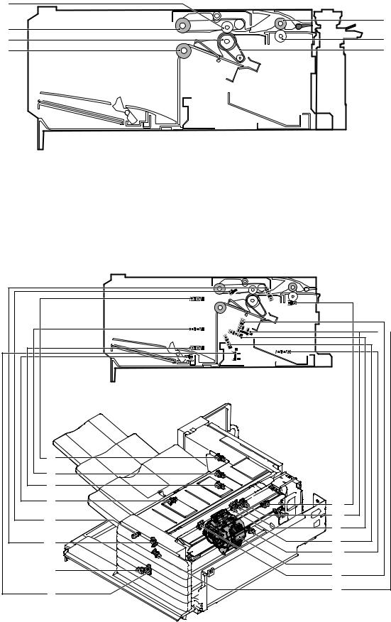
C. Motors, solenoids, and PWB
(1)MX-FNX1
3
 14
14  12
12
|
9 |
|
|
8 |
|
5 |
7 |
|
4 |
||
1 |
||
6 |
||
|
||
11 |
10 |
|
2 |
||
|
||
|
13 |
No. |
Signal |
Name |
Function |
1 |
FFSM |
Staple motor |
Drives the stapling mechanism. (Stapler unit built-in motor) |
2 |
FSM |
Staple shift motor |
Shifts the stapler unit in the F/R direction. |
3 |
FTLM |
Tray motor |
Drives the paper load tray up/down. |
4 |
FFJM |
Alignment motor F |
Drive the alignment guide on the F side. |
5 |
FRJM |
Alignment motor R |
Drive the alignment guide on the R side. |
6 |
FSWM |
Roller upper/lower roller |
Drives the bundle exit roller up/down. |
7 |
FAM |
Bundle exit motor |
Drives the bundle exit roller and the paddle. |
8 |
FRM |
Transport motor |
Drives the inlet port roller, the feed roller, and the take-up belt. |
9 |
FPDS |
Paddle one-rotation solenoid |
Trigger solenoid for paddle one-rotation. |
10 |
FSLS |
Paper surface detection solenoid |
Drives the lever for paper holding and detection of the tray paper surface. |
11 |
FBRS |
Belt separation solenoid |
Trigger solenoid for up/down shift of the take-up belt. |
12 |
FINRPS |
Flapper solenoid |
Drives the flapper to select the entry path between the finisher inside and the reverse path. |
13 |
FFAN |
Fan |
Cools the inlet port of the finisher. |
14 |
– |
Control PWB |
Controls the inner finisher. |
MX-FNX1/MX-PNX1 EXTERNAL VIEW AND INTERNAL STRUCTURE 4 – 4
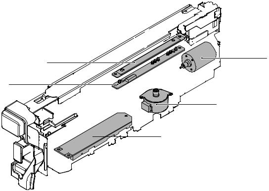
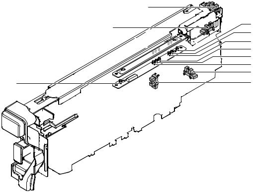
(2)MX-PNX1A/B/C/D
5 |
1 |
|
4
2
 3
3
No. |
Signal |
Name |
Function |
1 |
FPNM |
Punch motor |
Drives the punch unit up/down. |
2 |
FPSM |
Punch horizontal resist motor |
Shifts the punch unit to the center of paper. |
3 |
– |
Punch PWB |
Controls the punch unit. |
4 |
– |
LED light emitting PWB |
Detects the paper rear edge and the punch horizontal resist. |
5 |
– |
LED light receiving PWB |
Detects the paper rear edge and the punch horizontal resist. |
MX-FNX1/MX-PNX1 EXTERNAL VIEW AND INTERNAL STRUCTURE 4 – 5
[5] OPERATIONAL DESCRIPTIONS
1. Electrical mechanism diagram
A. Transport, paper exit section
|
PCB-CONT |
|
PF4141K200 |
|
FPDS |
FRLD |
FINRPS |
|
|
|
FRM |
FSWM |
|
|
FED |
|
FAM |
|
FBRD |
FBRS |
|
FDSW |
|
|
FFAN |
|
MX-FNX1/MX-PNX1 OPERATIONAL DESCRIPTIONS 5 – 1 |
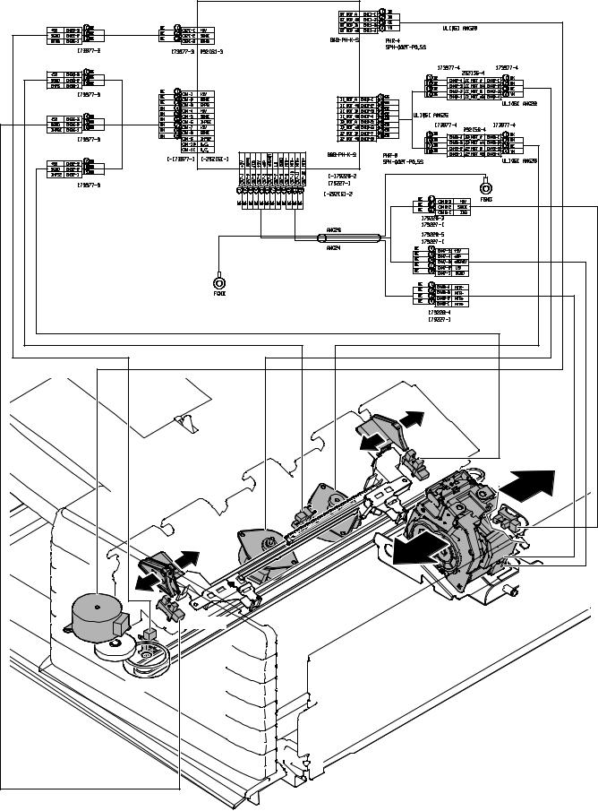
B. Staple section and aligment section
|
PCB-CONT |
|
|
PF4141K200 |
|
|
FRJHPD |
|
|
FRJM |
|
|
FSTPD |
FJPD |
|
|
|
|
FFJM |
|
|
|
FFSM |
|
|
FSHPD(*HP) |
FSM |
|
FSD(LS) |
|
FSTD(*READY) |
|
|
|
|
|
FFJHPD |
|
|
FSTHPD |
|
|
MX-FNX1/MX-PNX1 OPERATIONAL DESCRIPTIONS 5 – 2 |
|
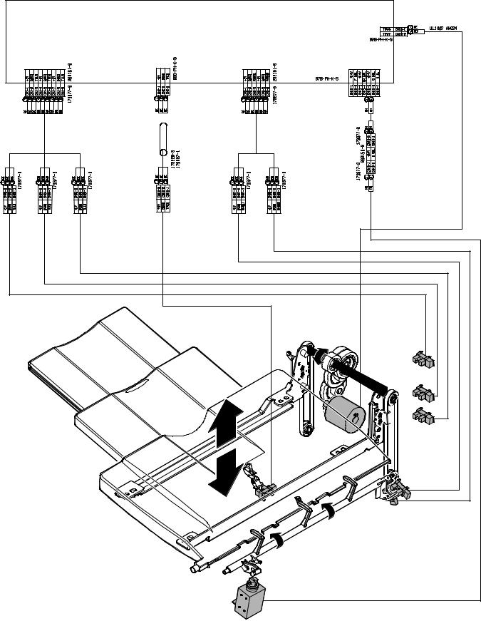
C. Paper exit tray section
PCB-CONT |
PF4141K200 |
FULD |
FMLLD |
FLLD |
FTLM |
FSLD1 |
FBED |
FSLD2 |
FSLS |
MX-FNX1/MX-PNX1 OPERATIONAL DESCRIPTIONS 5 – 3 |
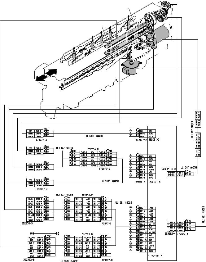
D. Punch unit (MX-PNX1A/B/C/D)
|
FPRPD |
|
FPPD1~FPPD6 |
|
FPHPD |
FPPEND |
|
|
FPNM |
|
FPSHPD |
FPDD |
FPSM |
|
PCB-PUNCH |
|
YA1035K200 |
MX-FNX1/MX-PNX1 OPERATIONAL DESCRIPTIONS 5 – 4 |
|

2. General
This chapter describes operations of the inner finisher. The major operation modes are as follows:
•Non-sort mode
•Offset mode
•Staple mode
•Non-sort mode + punch
•Offset mode + punch
•Staple mode + punch
In this chapter, the basic operations of the non-sort mode, the offset mode, and the staple mode are described.
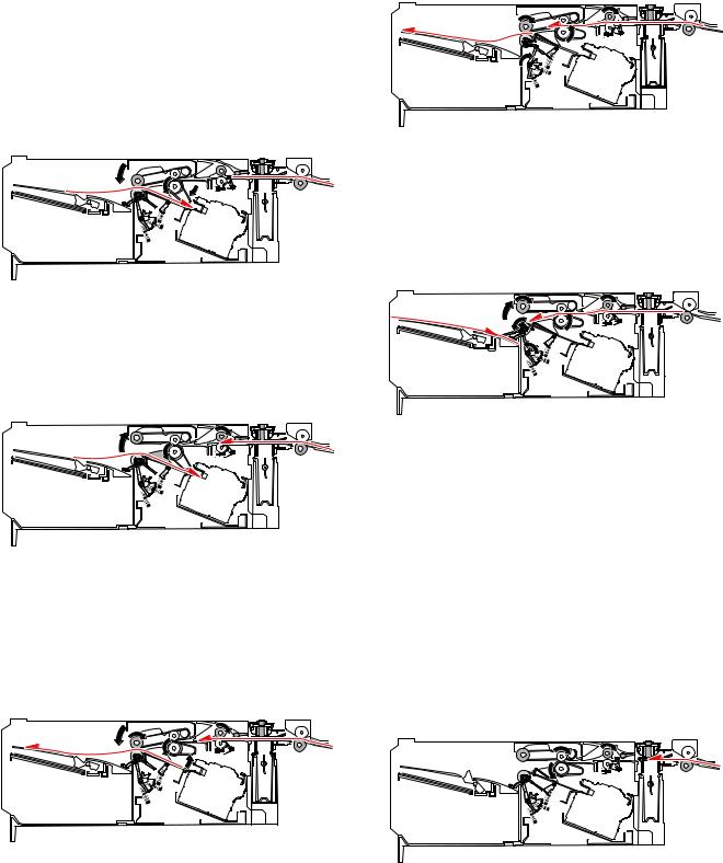
3. Outline of the transport path
The outline of the path is shown below.
1 |
2 |
3 |
4 |
5 |
6 |
7 |
8 |
9 |
10 |
||||||||||
|
|
|
|
|
|
|
|
|
|
|
|
|
|
|
|
|
|
|
|
|
|
|
|
|
|
|
|
|
|
|
|
|
|
|
|
|
|
|
|
|
|
|
|
|
|
|
|
|
|
|
|
|
|
|
|
|
|
|
|
|
|
|
|
|
|
|
|
|
|
|
|
|
|
|
|
|
|
|
|
|
|
|
|
|
|
|
|
|
|
|
|
|
|
|
|
|
|
|
|
|
|
|
|
|
|
|
|
|
|
|
|
|
|
|
|
|
|
|
|
|
|
|
|
|
|
|
|
|
|
|
|
|
|
|
|
|
|
|
|
|
|
|
14 |
|
|
|
|
11 |
||
|
|
|
|
|
|
|
||||
|
|
|
|
|
|
|
||||
|
15 |
13 |
12 |
|||||||
|
|
|
|
|
|
|
|
|
|
|
No. |
Name |
|
|
No. |
|
|
|
Name |
|
|
1 |
Tray |
|
9 |
Punch pin |
|
|
|
|||
2 |
Bundle exit roller |
|
10 |
Paper rear edge sensor (FPPEND) |
|
|||||
3 |
Paddle |
|
11 |
Main unit paper exit roller |
|
|||||
4 |
Alignment plate |
|
12 |
Stapler |
|
|
|
|||
5 |
Paper exit roller |
|
13 |
Paper stopper |
|
|||||
6 |
Take-up belt |
|
14 |
Empty sensor (FSTPD) |
|
|||||
7 |
Inlet port sensor (FED) |
|
15 |
Paper holding lever |
|
|||||
8 |
Inlet port roller |
|
|
|
|
|
|
|
|
|
MX-FNX1/MX-PNX1 OPERATIONAL DESCRIPTIONS 5 – 5

4. Non-sort mode
When the operation mode command is received from the copier, the finisher makes the finisher operation status command the JOB and starts the transport operation.
A.Reception of paper discharged from the main unit
1)The transport motor (FRM) is driven at the paper exit speed of the main unit to receive paper from the main unit.
2)After turning ON the inlet port sensor (FED), the roller up/down motor (FSWM) is driven to lower the bundle exit roller. The bundle exit motor (FAM) is driven at the paper exit speed of the main unit to drive the bundle exit roller. When the paper width is 210mm or more, the alignment motor F (FFJM) and the alignment motor R (FRJM) are driven by turning ON the inlet port sensor (FED) to shift the alignment plate to 15mm inside the paper and put it under the paper.
3)In the case of the punch mode, punching is performed as described in "7. Punching process."
B. Paper exit
1)After the paper rear edge passes the paper exit roller of the main unit, the transport motor (FRM) and the bundle exit motor (FAM) are accelerated to 300mm/sec. When the paper rear edge passes the inlet port sensor (FED) and then transport of a certain amount is made, the alignment plate is shifted to the home position.
Before the paper rear edge passes the bundle exit roller, the paper surface detection solenoid (FSLS) is turned OFF and the bundle exit roller speed is decelerated to 100mm/sec at the same time, performing paper exit deceleration of paper.
2)Immediately after the paper rear edge passes the bundle exit roller, the paddle one-rotation solenoid (FPDS) is turned ON to take-up the paper falling onto the tray.
3)When paper is transported by 10mm after the paper rear edge passes the bundle exit roller, the bundle exit motor (FAM) is accelerated to 200mm/sec. Just before the paddle passes the load tray, the paper surface detection solenoid (FSLS) is turned ON to hold the paper discharged by the paper holding lever.
4)When the paddle rotates one turn, the bundle exit motor (FAM) is stopped.
5)When there is next paper, repeat the procedures from "A-1)."
6)When there is no next paper, the actuators are turned OFF and the finisher operation status command is set to READY, and the transport operation is terminated.
5. Offset mode
When the operation mode command is received from the copier, the finisher makes the finisher operation status command the JOB and starts the transport operation.
A.Reception of paper discharged from the main unit
1)The transport motor (FRM) is driven at the paper exit speed of the main unit to receive paper from the main unit. When the paper length is 216mm or less, the paper exit speed of the second and later sheets from the main unit is 280mm/sec.
B. Paper take-up and alignment
1)For the first sheet of a bundle, the inlet port sensor (FED) is turned ON and the roller up/down motor (FSWM) is driven to lower the bundle exit roller. The bundle exit motor (FAM) is driven at the paper exit speed of the main unit to drive the bundle exit roller.
In addition, the alignment motor F (FFJM) and the alignment motor R (FRJM) are driven by turning ON the inlet port sensor (FED) to shift the alignment plate to 15mm outside the paper, and enter the standby state. After transport of a certain amount, the roller up/down motor (FSWM) is driven to lift the bundle exit roller, stopping the bundle exit motor (FAM).
MX-FNX1/MX-PNX1 OPERATIONAL DESCRIPTIONS 5 – 6
2)For the second and later sheets of a bundle, the inlet port sensor (FED) turns ON and a certain amount is transported, and then the alignment motor F (FFJM) and the alignment motor R (FRJM) are driven to shift the alignment plate to 15mm outside the paper and to put it under the standby state.
3)After the paper rear edge passes the paper exit roller of the main unit, the transport motor (FRM) is accelerated to 480mm/ sec.
4)In the punch mode, punching is performed as described in "7. Punching process."
5)When the paper rear edge passes the inlet port sensor (FED) and a certain amount is transported, the roller up/down motor (FSWM) is driven to lower the bundle exit roller and the bundle exit motor (FAM) is driven for a certain amount in the take-up direction at the paper exit speed of the main unit to take up paper to the process tray. In addition, the belt separation solenoid (FBRS) is turned ON to lower the take-up belt.
6)After completion of take-up, the roller up/down motor (FSWM) is driven to lift the bundle exit roller. The alignment motor F (FFJM) and the alignment motor R (FRJM) are driven for a certain amount to align paper in the process tray. If there are two or more sheets to be aligned, the procedures are repeated from "A-1)" for the specified number of sheets. However, the paper exit operation of "C. Aligned paper exit" is performed for every 3 sheets.
C. Aligned paper exit
1)After completion of alignment, the belt separation solenoid (FBRS) is turned ON to lift the take-up belt. The alignment motor F (FFJM) and the alignment motor R (FRJM) are driven to separate paper from the alignment plate by 1mm. In addition, the roller up/down motor (FSWM) is driven to lower the bundle exit roller. The bundle exit motor (FAM) is started at the speed of 450mm/sec and paper in the process tray is discharged.
2)After transport of paper by a certain amount, the alignment motor F (FFJM) and the alignment motor R (FRJM) are driven to shift the alignment plate to the home position.
3)When the paper rear edge passes the empty sensor (FSTPD), the paper surface detection solenoid (FSLS) is turned OFF and the bundle exit roller speed is decelerated to 100mm/sec at the same time, decelerating the paper exit operation.
4)Immediately after the paper rear edge passes the bundle exit roller, the paddle one-rotation solenoid (FPDS) is turned ON to take up paper falling onto the tray.
5)When the paper rear edge passes the bundle exit roller and the paper is transported for 10mm, the bundle exit motor (FAM) is accelerated to 200mm/sec. Before the paddle passes the load tray, the paper surface detection solenoid (FSLS) is turned ON to hold the discharged paper with the paper holding lever.
6)When the paddle rotates one turn, the bundle exit motor (FAM) is stopped.
7)When there is next paper, the procedures are repeated from "A-1)."
8)When there is no next paper, the actuators are turned OFF and the finisher operation status command is set to READY to terminate the transport operation.
6. Staple mode
When the operation mode command is received from the copier, the finisher makes the finisher operation status command the JOB and starts the transport operation.
A.Reception of paper discharged from the main unit
1)The transport motor (FRM) is driven at the paper exit speed of the main unit to receive paper from the main unit. When the paper length is 216mm or less, the paper exit speed of the second and later sheets from the main unit is 280mm/sec.
MX-FNX1/MX-PNX1 OPERATIONAL DESCRIPTIONS 5 – 7

B. Paper take-up, alignment and staple
1)For the first sheet of a bundle, after turning on the inlet sensor (FED), the roller up/down motor (FSWM) is driven to lower the bundle exit roller. The bundle exit motor (FAM) is driven at the paper exit speed of the main unit to drive the bundle exit roller. By turning on the inlet port sensor (FED), the alignment motor F (FFJM) and the alignment motor R (FRJM) are driven to shift the alignment plate to 15mm outside the paper and to put it under the standby state. After transport of a certain amount, the roller up/down motor (FSWM) is driven to lift the bundle exit roller to terminate the bundle exit motor (FAM).
8)After completion of alignment of a specified number of sheets, the staple motor (FFSM) is started to staple at the specified position.
2)For the second and later sheets, after transporting paper from the inlet port sensor (FED) by a certain amount, the alignment motor F (FFJM) and the alignment motor R (FRJM) are driven to shift the alignment plate to 15mm outside the paper and to put it under the standby state.
3)For the last sheet of a bundle, the inlet port sensor (FED) is turned ON to drive the staple shift motor (FSM) to shift the stapler to the binding position.
4)After the paper rear edge passed the paper exit roller of the main unit, the transport motor (FRM) is accelerated to 480mm/ sec.
5)In the punch mode, punching is performed as described in "7. Punching process."
6)When the paper rear edge passes the inlet port sensor (FED) and paper is transported by a certain amount, the roller up/ down motor (FSWM) is driven to lower the bundle roller and the bundle exit motor (FAM) is driven in the take-up direction at the paper exit speed of the main unit by a certain amount to take up paper to the process tray. In addition, the belt separation solenoid (FBRS) is turned ON to lower the take-up belt.
7)After completion of take-up, the roller up/down motor (FSWM) is driven to lift the bundle exit roller. The alignment motor F (FFJM) and the alignment motor R (FRJM) are driven by a certain amount to align paper in the process tray. If there are two or more sheets to be aligned, the operation is repeated from "A-1)."
C. Aligned and stapled paper exit
1)After completion of stapling, the belt separation solenoid (FBRS) is turned ON to lift the take-up belt. The alignment motor F (FFJM) and the alignment motor R (FRJM) are driven to shift the alignment plate by 1mm from paper. Then the roller up/down motor (FSWM) is driven to lower the bundle exit roller to press, and the bundle exit motor (FAM) is started at 450mm/ sec to discharge paper from the process tray.
2)After transporting paper by a certain amount, the alignment motor F (FFJM) and the alignment motor R (FRJM) are driven to shift the alignment plate to the home position.
3)After the paper rear edge passes the empty sensor (FSTPD), the paper surface detection solenoid (FSLS) is turned OFF and the bundle exit roller speed is decelerated to 100mm/sec at the same time to decelerate paper exit of the paper bundle. At the same time, the roller up/down motor (FSWM) is driven in the lifting direction to decrease the pressure of the bundle roller. In addition, the tray motor (FTLM) is driven to lower the load tray by 5mm.
4)Immediately after the paper rear edge passes the bundle exit roller, the paddle one-rotation solenoid (FPDS) is turned ON to take up roller falling onto the tray.
5)When paper is transported by 10mm after the paper rear edge passes the bundle exit roller, the bundle exit motor (FAM) is decelerated to 200mm/sec.
MX-FNX1/MX-PNX1 OPERATIONAL DESCRIPTIONS 5 – 8

6)When the paddle rotates one turn, the bundle exit motor (FAM) is stopped.
7)After the paddle rotates one turn, the paper surface detection solenoid (FSLS) is turned ON for 100msec and then OFF. Then it is turned ON after 400msec. At that time, if the paper surface level is lower than the reference level, the tray motor (FTLM) is driven to lift the load tray to the reference level.
8)If there is next paper, the operation is repeated from "A-1)."
9)If there is no next paper, the actuators are turned OFF and the finisher operation status command is set to READY state, and the transport operation is terminated.
7. Punching process
When the operation mode command is received from the copier, the finisher makes the finisher operation status command the JOB and starts the transport operation.
A.Reception of paper discharged from the main unit
1)The transport motor (FRM) is driven at the paper exit speed of the main unit to receive paper from the main unit. When the paper length is 216mm or less in the offset mode or in the staple mode, the paper exit speed of the second and later sheets of the same bundle from the main unit is 280mm/sec.
B. Punching process 1
1)When the paper rear edge passes the paper rear edge sensor, the transport motor (FRM) is stopped and paper transport is stopped.
2)When the paper is stopped, the punch motor (FPNM) is driven to punch at the paper rear edge.
C. Punching process 2
1)After completion of punching, the transport motor (FRM) and the bundle exit motor (FAM) are driven to transport paper and the specified after-process is executed. The motor speed is 300mm/sec for the non-sort mode, and 480mm/sec for the offset mode or the staple mode.
MX-FNX1/MX-PNX1 OPERATIONAL DESCRIPTIONS 5 – 9
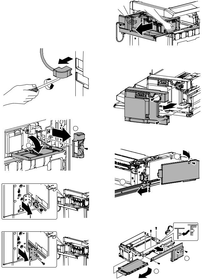
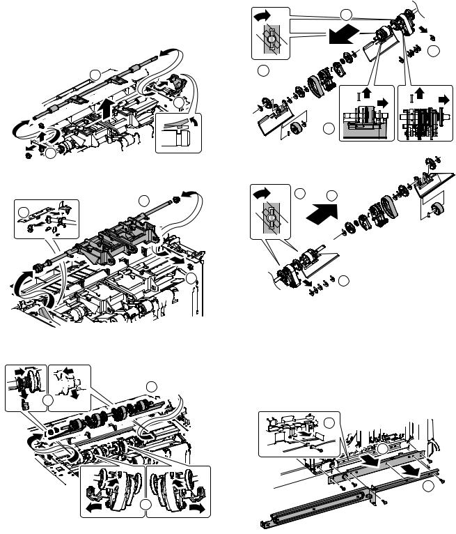
[6]DISASSEMBLY AND ASSEMBLY
1. MX-FNX1
A. Exterior
(1)Inner finisher
1)Loosen the screw, and disconnect the connector from the main unit.
2)Open the front cover, and remove the punch unit cover.
2
1
3)Remove the stopper.
4)Remove the screw, and remove the rail stay.
5)Remove the inner finisher from the main unit.
(2)Inner cover
1)Remove the inner finisher from the main unit. Refer to A-(1).
2)Remove the inner cover.
(3)Rear cover
1)Remove the inner finisher from the main unit. Refer to A-(1).
2)Slide the rail, and remove the rear cover.
2

1
(4)Left cover, bottom cover
1)Remove the inner finisher from the main unit. Refer to A-(1).
2)Remove the left cover and the bottom cover.
1
2
MX-FNX1/MX-PNX1 DISASSEMBLY AND ASSEMBLY 6 – 1
(5)Reverse guide unit
1)Remove the inner finisher from the main unit. Refer to A-(1).
2)Remove the inner cover. Refer to A-(2).
3)Remove the reverse guide unit.
B. Transport section, paper exit section
(1)Paddle
1)Open the front cover, and slide the inner finisher.
2

 1
1 
2)Remove the paddle holders, and remove the paddles.
(2)Flapper solenoid
1)Remove the inner finisher from the main unit. Refer to A-(1).
2)Disconnect the connector, and remove the flapper solenoid.
*When installing, shift and fix the solenoid so that the reverse flapper and the cushion material are in contact with each other with the solenoid plunger pushed in.
(3)Inlet port sensor
1)Remove the inner finisher from the main unit. Refer to A-(1).
2)Remove the sensor holder, and remove the inlet port sensor.
MX-FNX1/MX-PNX1 DISASSEMBLY AND ASSEMBLY 6 – 2
(4)Roller up/down sensor
1)Remove the inner finisher from the main unit. Refer to A-(1).
2)Remove the inner cover. Refer to A-(2).
3)Remove the bracket, and remove the roller up/down sensor.
(5)Take-up belt sensor
1)Remove the inner finisher from the main unit. Refer to A-(1).
2)Remove the inner cover. Refer to A-(2).
3)Slide the harness guide, remove the bracket, and remove the take-up belt sensor.
2
1
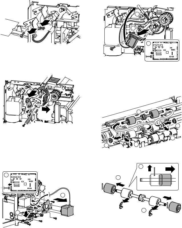
(6)Roller up/down motor
1)Remove the inner finisher from the main unit. Refer to A-(1).
2)Remove the inner cover. Refer to A-(2).
3)Remove the rear cover. Refer to A-(3).
4)Remove the reverse guide unit.
5)Slide the stapler drive unit. Disconnect the connector from the PWB. Remove the roller up/down motor unit. Remove the roller up/down motor.
1
3
2 |
(7)Belt separation solenoid
1)Remove the inner finisher from the main unit. Refer to A-(1).
2)Remove the inner cover. Refer to A-(2).
3)Remove the reverse guide unit. Refer to A-(5).
4)Remove the parts, and remove the belt separation solenoid.
2
3
1
(8)Bundle exit paper transport roller
1)Remove the inner finisher from the main unit. Refer to A-(1).
2)Remove the inner cover. Refer to A-(2).
3)Remove the reverse guide unit. Refer to A-(5).
4)Remove the parts, and remove the bundle exit paper transport roller unit.
3
2
1
2 |
1 |
|
5)Remove the parts, and remove the bundle exit paper transport roller.
2
3
1
MX-FNX1/MX-PNX1 DISASSEMBLY AND ASSEMBLY 6 – 3
(9)Take-up belt, paper exit roller
1)Remove the inner finisher from the main unit. Refer to A-(1).
2)Remove the inner cover. Refer to A-(2).
3)Remove the reverse guide unit. Refer to A-(5).
4)Remove the parts, and remove the bundle roller up/down lever unit.
2
1
1
5)Remove the parts, and remove the bundle roller unit.
2
1
 1
1
6)Remove the parts, and pull out the belt unit. Remove the parts, and remove the belt unit.
 3 1
3 1 


2
7)Remove the parts, and remove the take-up belt and the paper exit roller.
3
1
2
2
2 3
1
(10) Inlet port gate
1)Remove the inner finisher from the main unit. Refer to A-(1).
2)Remove the inner cover. Refer to A-(2).
3)Remove the left cover and the bottom cover. Refer to A-(4).
4)Remove the reverse guide unit. Refer to A-(5).
5)Remove the PWB. Refer to F-(1).
6)Remove the flapper solenoid. Refer to B-(2).
7)Remove the slide rail. Remove the slider fixing bracket and remove the earth terminal.
3


 2
2
 1
1 
MX-FNX1/MX-PNX1 DISASSEMBLY AND ASSEMBLY 6 – 4

8)Remove the tray unit.
9)Remove the harness from the guide, and remove the bottom plate.
(11) Inlet port paper transport roller
1)Remove the inner finisher from the main unit. Refer to A-(1).
2)Remove the inner cover. Refer to A-(2).
3)Remove the tray unit. Refer to B-(10).
4)Remove the bottom plate. Refer to B-(10).
5)Remove the inlet port upper guide, and remove the transport guide.
6)Remove the parts, and remove the inlet port paper transport roller.
10) Remove the inlet port upper guide.
11)Remove the spring, and remove the parts. Remove the inlet port gate.
2
3


 1
1
4
1
1
2 |
3 |
2
(12) Transport motor
1)Remove the inner finisher from the main unit. Refer to A-(1).
2)Remove the inner cover. Refer to A-(2).
3)Remove the tray unit. Refer to B-(10).
4)Remove the bottom plate. Refer to B-(10).
5)Disconnect the connector, and remove the transport motor.
 1
1
3
2
MX-FNX1/MX-PNX1 DISASSEMBLY AND ASSEMBLY 6 – 5
Loading...