


Ordering number: EN2551C
Monolithic Digital IC
LB1660N, 1661, 1664N, 1665
2-Phase Unipolar Brushless Motor Drivers
Applications
. 2-phase unipolar brushless motor (ex. DC brushless fan motor) drivers
Features and Functions
. Output current : 1.5 A
. On-chip output protect zener diodes : 60 V (LB1660N,
. 1664N)
. Output stage withstand voltage: 85 V (LB1661, 1665)
. On-chip hall input amplifier
. On-chip protector against lock With lock detect pin
Package Dimensions
unit : mm
3001B-DIP8
[LB1661N, 1661]
SANYO : DIP8
unit : mm
3054A-DIP16F
[LB1664N, 1665]
SANYO : DIP16F
SANYO Electric Co.,Ltd. Semiconductor Bussiness Headquarters
TOKYO OFFICE Tokyo Bldg., 1-10, 1 Chome, Ueno, Taito-ku, TOKYO, 110 JAPAN
O1096HA(II) 7037KI/6227TA No.2251-1/9
LB1660N, 1661, 1664N, 1665
Classification
The LB1660 series are classified by the package and whether the on-chip output stage zener diode is used or not, as follows.
Output stage zener diode |
With (VZ = 59 V) |
Without (Vor = 85 V) |
Package |
|
|
|
|
|
DIP8 (Pd = 1.2 W) |
LB1660N |
LB1661 |
|
|
|
DIP16F (Pd = 2.0 W) |
LB1664N |
LB1665 |
|
|
|
It is recommended to use the LB1661, 1665 in the following cases.
1A capacitor is connected across the output and GND and the back emf is more than VZ = 59 V
2External zener diodes are connected to absorb the kickback voltage.
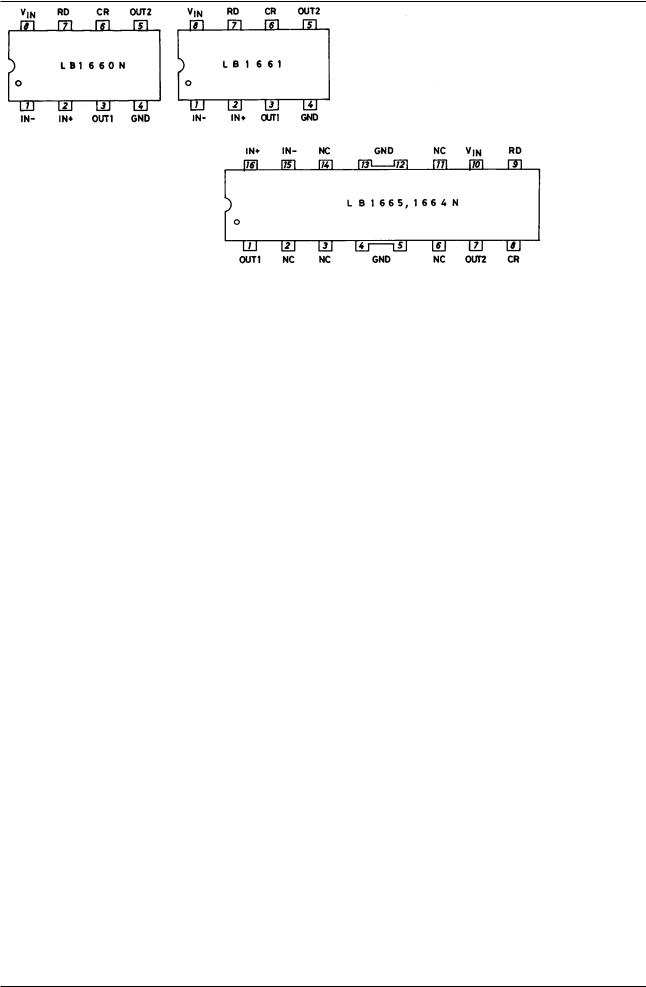
Pin Assignments
Top view
Truth Table
IN+ |
IN− |
CR |
OUT1 |
OUT2 |
|
|
|
|
|
H |
L |
L |
H |
L |
|
|
|
|
|
L |
H |
L |
L |
H |
H |
L |
H |
H |
H |
L |
H |
H |
H |
H |
|
|
|
|
|
No.2551-2/9
LB1660N, 1661, 1664N, 1665
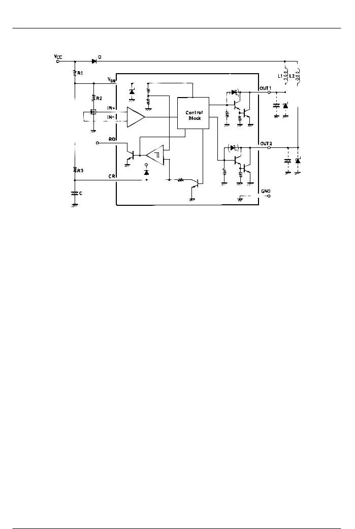
Equivalent Circuit Block Diagram and Sample Application Circuit
The LB1661, LB1665 have no output stage protect zener diode.
[LB1660N]
Absolute Maximum Ratings at Ta = 25°C
Parameter |
Symbol |
Conditions |
Ratings |
Unit |
|
|
|
|
|
Maximum input current |
ICC max |
t % 20 ms |
200 |
mA |
Output supply voltage |
VO max |
|
Internal |
V |
Maximum output current |
IO max |
|
1.5 |
A |
Output negative current |
IOM |
t % 20 µs |
−50 |
mA |
RD flow-in current |
IRD |
|
5 |
mA |
RD supply voltage |
VRD |
|
30 |
V |
Allowable power dissipation |
Pd max |
|
1.2 |
W |
|
|
|
|
|
Operating temperature |
Topr |
|
−30 to +80 |
°C |
|
|
|
|
|
Storage temperature |
Tstg |
|
−55 to +125 |
°C |
|
|
|
|
|
Allowable Operating Conditions at Ta = 25°C |
|
|
||
|
|
|
|
|
Parameter |
Symbol |
Conditions |
Ratings |
Unit |
|
|
|
|
|
Input current range |
ICC |
|
7.0 to 50.0 |
mA |
Common-mode input voltage range |
VICM |
|
0 to VIN-1.5 |
V |
No.2551-3/9
 Loading...