


Ordering number : EN4715A
Monolithic Linear IC
LA1193M, 1193V
High-Performance FM Front End for Car Radios
Overview
The LA1193M and LA1193V are front-end ICs developed for use in car radios. It incorporates an extremely wide dynamic range mixer and a new AGC system consisting of a dual-system wide-band AGC and a new keyed AGC to provide excellent interference suppression characteristics.
•Improved temperature characteristics
—Conversion gain
—AGC sensitivity
—Antenna damping drive output current
Package Dimensions
unit: mm
3036B-MFP20
Functions
•Double-balance mixer
•Pin diode drive output
•Differential IF amplifier
•Dual-system wide-band AGC circuit
•Local buffer output
•3D-AGC system
•FET gate drive AGC output
•IF amplifier gain control pin
Features
•Improved interference characteristics
—Expanded mixer input dynamic range Mixer input usable sensitivity: 15 dBµ
Mixer input I.M. QS: 90 dBµ
(The dynamic range has been increased by 6 dB over the earlier LA1175M.)
—Development of a new wide-band AGC circuit Improved interference characteristics for both nearchannel interference and far-channel interference Improved interference characteristics for the TV band
—Development of a 3D-AGC system
The adjacent channel two-signal interference characteristics can be effectively improved without degrading the strong-field three-signal interference characteristics during keyed AGC operation.
•Improved stability design
—AGC circuit local oscillator isolation
Measures were taken to prevent the deterioration of AMR, noise level, THD and other characteristics during AGC operation.
—AGC circuit incorrect operation measures
The LA1193M provides methods to prevent incorrect operation due to local oscillator injection and loss of DC balance.
[LA1193M]
unit: mm
3179A-SSOP20
[LA1193V]
SANYO: SSOP20
SANYO Electric Co.,Ltd. Semiconductor Bussiness Headquarters
TOKYO OFFICE Tokyo Bldg., 1-10, 1 Chome, Ueno, Taito-ku, TOKYO, 110 JAPAN
31097HA (OT)/61094TH(OT) A8-9997 No. 4715-1/21

LA1193M, 1193V
Specifications
Maximum Ratings at Ta = 25°C
Parameter |
Symbol |
Conditions |
Ratings |
Unit |
||
|
|
|
|
|
|
|
Maximum supply voltage |
VCC max |
VCC for pins 5 and 17 |
9 |
V |
||
VCC max mix |
VCC for pins 10 and 11 |
15 |
V |
|||
|
||||||
|
Pd max |
LA1193M: (Ta ≤ 70°C) |
500 |
mW |
||
Allowable power dissipation |
Mounted on a 41 × 30 × 1.1 mm3 glass-Epoxy board |
|||||
|
|
|
|
|
||
Pd max |
LA1193V: (Ta ≤ 70°C) |
500 |
mW |
|||
|
||||||
|
Mounted on a 23 × 36 × 1.6 mm3 glass-Epoxy board |
|||||
|
|
|
|
|
|
|
Operating temperature |
Topr |
* |
–40 to +85 |
°C |
||
|
|
|
|
|
|
|
Storage temperature |
Tstg |
|
–40 to +125 |
°C |
||
|
|
|
|
|
|
|
Note: * Connect a resistor (up to 10 kΩ ) between pins 17 and 19. |
|
|
||||
Operating Conditions at Ta = 25°C |
|
|
|
|||
|
|
|
|
|
|
|
Parameter |
Symbol |
|
Conditions |
Ratings |
Unit |
|
|
|
|
|
|
|
|
Recommended supply voltage |
VCC |
|
|
8.0 |
V |
|
Operating supply voltage range |
VCC op |
|
|
7.6 to 9 |
V |
|
Operating Characteristics at Ta = 25°C, VCC = 8.0 V, in the specified test circuit, f = 88 MHz, fOSC = 77.3 MHz
Parameter |
Symbol |
|
Conditions |
|
Ratings |
|
Unit |
|
|
|
|
|
|||||
|
min |
typ |
max |
|||||
|
|
|
|
|
||||
|
|
|
|
|
|
|
||
Current drain |
ICCO |
No input, VCONT = 0 V |
19 |
24 |
29 |
mA |
||
Antenna damping current |
ANT-DI |
88 |
MHz, 100 dBµ, VCONT = 4.0 V |
7.0 |
9.5 |
12.5 |
mA |
|
AGC high voltage |
VAGC-H |
88 |
MHz, 0 dBµ, VCONT = 4.0 V |
7.6 |
7.9 |
|
V |
|
AGC low voltage |
VAGC-L |
88 |
MHz, 100 dBµ, VCONT = 4.0 V |
|
0.4 |
0.9 |
V |
|
Saturation output voltage |
VOUT |
88 |
MHz, 110 dBµ, VCONT = 4.0 V |
97 |
110 |
|
dBµ |
|
–3 dB limiting sensitivity |
Vi-Limit |
88 |
MHz, 110 dBµ, VCONT = 4.0 V |
78 |
85 |
92 |
dBµ |
|
Conversion gain |
A. V |
88 |
MHz, 75 dBµ, VCONT = 4.0 V |
98 |
101 |
104 |
dBµ |
|
Local buffer output |
VOSC-Buff |
No input, no modulation |
105 |
109 |
|
dBµ |
||
Narrow VAGC-ON |
V-NAGC |
88 |
MHZ, VCONT = 4.0 V, at an input level |
73 |
80 |
87 |
dBµ |
|
such that VAGC-OUT is 2 V or less |
(76) |
(83) |
(90) |
|
||||
|
|
|
||||||
Wide VAGC-ON |
V-WAGC |
88 |
MHZ, VCONT = 0 V, at an input level |
97 |
101 |
105 |
dBµ |
|
such that VAGC-OUT is 2 V or less |
||||||||
|
|
|
|
|
|
|||
|
|
88 |
MHZ, VCONT variable, with 95 dBµ |
|
|
|
|
|
3D-AGC-ON |
V3D-AGC |
being the VCONT voltage input such that |
0.4 |
0.6 |
0.8 |
V |
||
VAGC-OUT switches from high to low and |
||||||||
|
|
|
|
|
|
|||
|
|
2.0 V as the VAGC threshold value. |
|
|
|
|
||
Note: Values in parenthesis are for LA1193V.
No. 4715-2/21
LA1193M, 1193V
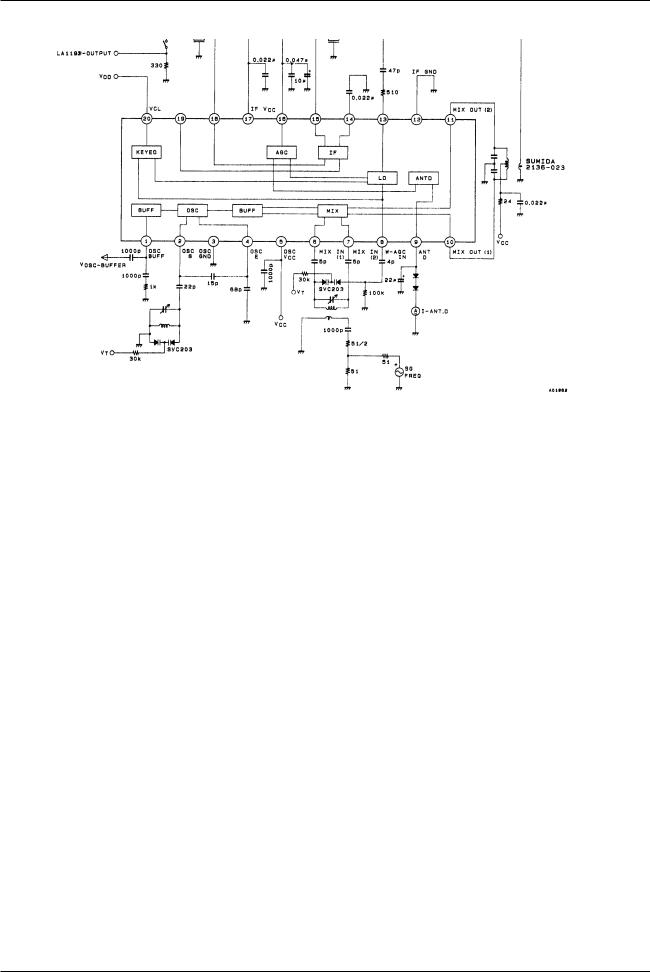
Block Diagram and Test Circuit Diagram
Unit (Resistance: Ω , Capacitance: F)
Application Circuit: USA and Europe
Unit (Resistance: Ω , Capacitance: F)
No. 4715-3/21

LA1193M, 1193V
Application Circuit: Japan
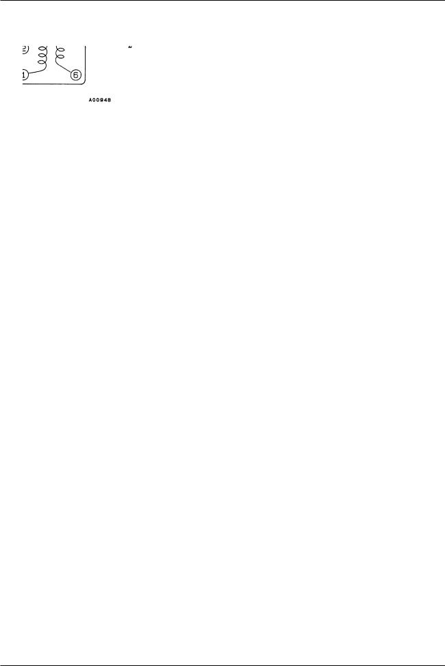
Coil Specifications |
Unit (Resistance: Ω , Capacitance: F) |
|
|
Coils Manufactured by Sumida Electronics |
|
Japan band RF coil SA-129 or SA-143 |
Japan oscillator coil SA-125 |
Japan antenna coil SA-123 or SA-144 |
US band RF coil SA142 or SA-250 |
Continued on next page.
No. 4715-4/21
LA1193M, 1193V
Continued from preceding page.
US band antenna coil SA-140 or SA-231 |
US band oscillator coil SA-278 |
Mixer coil (for both bands) SA-266
Pin Functions
Pin No. |
|
Function |
|
|
Equivalent circuit |
|
Note |
||
|
|
|
|
|
|
|
|
|
|
|
|
|
|
|
|
|
|
|
|
1 |
|
OSC BUFF |
|
|
|
|
|
|
|
|
|
|
|
|
|
|
|
|
|
|
|
|
|
|
|
|
|
|
|
|
|
|
|
|
|
|
|
|
|
2 |
|
|
|
|
|
|
|
|
|
|
OSC Tr. base |
|
|
|
|
|
|
|
|
3 |
|
OSC GND |
|
|
|
|
|
Colpitts oscillator |
|
4 |
|
OSC Tr. emitter |
|
|
|
|
|
|
|
|
|
|
|
|
|
|
|
||
5 |
|
OSC VCC |
|
|
|
|
|
|
|
|
|
|
|
|
|
|
|
|
|
|
|
|
|
|
|
|
|
|
|
|
|
|
|
|
|
|
|
|
|
Continued on next page.
No. 4715-5/21

LA1193M, 1193V
Continued from preceding page.
Pin No. |
|
Function |
|
|
|
Equivalent circuit |
|
Note |
||
|
|
|
|
|
|
|
|
|
|
|
|
|
|
|
|
|
|
|
|
|
|
|
|
|
|
|
|
|
|
|
Mixer input usable sensitivity |
|
|
|
|
|
|
|
|
|
|
|
|
|
|
|
|
|
|
|
|
|
15 dBµ |
|
6 |
|
Mix input (1) |
|
|
|
|
|
|
Mixer input I.M. QS |
|
7 |
|
Mix input (2) |
|
|
|
|
|
|
90.5 dBµ |
|
|
|
|
|
|
|
|
(6.5 dB higher than previous products) |
|
||
10 |
|
Mix out (1) |
|
|
|
|
|
|
|
|
|
|
|
|
|
|
|
Conversion gain |
|
||
11 |
|
Mix out (2) |
|
|
|
|
|
|
|
|
|
|
|
|
|
|
|
15 dB |
|
||
|
|
|
|
|
|
|
|
|
Input impedance |
|
|
|
|
|
|
|
|
|
|
25 Ω |
|
|
|
|
|
|
|
|
|
|
|
|
|
|
|
|
|
|
|
|
|
|
|
|
|
|
|
|
|
|
|
|
|
|
9 |
|
Antenna damping |
|
|
|
|
|
|
IANTD = 10 mA |
|
|
drive output |
|
|
|
|
|
|
|
||
|
|
|
|
|
|
|
|
|
|
|
|
|
|
|
|
|
|
|
|
|
|
|
|
|
|
|
|
|
|
|
|
|
12 |
|
|
|
|
|
|
|
|
|
|
|
IF GND |
|
|
|
|
|
|
|
|
|
|
|
|
|
|
|
|
|
|
|
|
|
|
|
|
|
|
|
|
|
|
|
|
|
|
|
|
|
|
|
|
Since the DC cut capacitor is provided on-chip in the |
|
8 |
|
W-AGC input |
|
|
|
|
|
|
pin internal circuit, we have taken steps to prevent |
|
|
|
|
|
|
|
|
incorrect AGC operation due to inter-pin leakage |
|
||
|
|
|
|
|
|
|
|
|
|
|
|
|
|
|
|
|
|
|
|
currents. |
|
|
|
|
|
|
|
|
|
|
|
|
|
|
|
|
|
|
|
|
|
|
|
Continued on next page.
No. 4715-6/21
LA1193M, 1193V
Continued from preceding page.
Pin No. |
|
Function |
|
|
Equivalent circuit |
|
Note |
|
||
|
|
|
|
|
|
|
|
|
|
|
|
|
|
|
|
|
|
|
|
|
|
|
|
|
|
|
|
|
|
|
Since the DC cut capacitor is provided on-chip in the |
|
13 |
|
N-AGC input |
|
|
|
|
|
|
pin internal circuit, we have taken steps to prevent |
|
|
|
|
|
|
|
|
incorrect AGC operation due to inter-pin leakage |
|
||
|
|
|
|
|
|
|
|
|
|
|
|
|
|
|
|
|
|
|
|
currents. |
|
|
|
|
|
|
|
|
|
|
|
|
|
|
|
|
|
|
|
|
|
|
|
|
|
|
|
|
|
|
|
|
|
|
14 |
|
IF AMP bypass |
|
|
|
|
|
|
IF gain: 25 dB |
|
|
|
|
|
|
|
|
Input and output impedances of 330 Ω |
|
||
15 |
|
IF AMP input |
|
|
|
|
|
|
|
|
|
|
|
|
|
|
|
The IF gain can be adjusted by inserting a resistor |
|
||
18 |
|
IF AMP output |
|
|
|
|
|
|
between pins 17 and 19. |
|
19 |
|
IF AMP gain adjust |
|
|
|
|
|
|
The gain is at its maximum when there is no resistor |
|
|
|
|
|
|
|
|
inserted. |
|
||
|
|
|
|
|
|
|
|
|
|
|
|
|
|
|
|
|
|
|
|
|
|
|
|
|
|
|
|
|
|
|
|
|
|
|
|
|
|
|
|
|
|
|
|
16 |
|
RF AGC output |
|
|
|
|
|
|
MOSFET |
|
|
|
|
|
|
|
|
Second gate control |
|
||
|
|
|
|
|
|
|
|
|
|
|
|
|
|
|
|
|
|
|
|
|
|
|
|
|
|
|
|
|
|
|
|
|
17 |
|
IF, AGC, VCC |
|
|
|
|
|
|
|
|
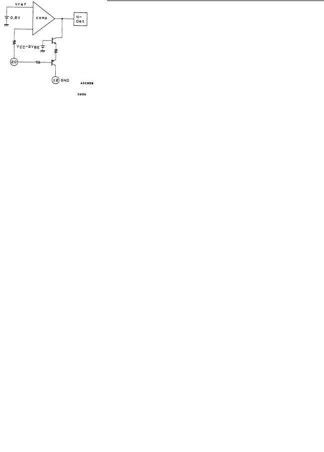
20 |
|
|
|
|
|
|
|
|
|
|
|
|
|
|
|
|
|
|
|
|
|
|
Keyed AGC input |
|
|
|
|
|
|
Controls the narrow AGC. |
|
|
|
|
|
|
|
|
|
|
|
|
|
|
|
|
|
|
|
|
|
|
|
|
|
|
|
|
|
|
|
|
|
|
|
No. 4715-7/21
 Loading...