


LA6458S
High-Performance
Dual Operational Amplifiers
Overview
The LA6458 consists of two independent, internally phase
compensated operational amplifiers. Application areas include
active filters, audio preamplifiers, and various electronic
circuits.
Features
.
LA6458M : 8-pin MFP package,
LA6458S : 9-pin SIP package
.
Phase compensation circuit built in.
.
High gain, low noise.
.
Slew rate : l.1V/µs typ.
Specifications
Maximum Ratings at Ta = 25°C
Parameter Symbol Conditions Ratings Unit
Maximum
supply voltage
V
CC
/V
EE
±18 V
Differential
input voltage
V
ID
±30 V
Common-mode
input voltage
V
IN
±15 V
Allowable
power
dissipation
Pd max
LA6458M 300 mW
LA6458S 500 mW
Operating
temperature
Topr –20 to +75 °C
Storage
temperature
Tstg –40 to +125 °C
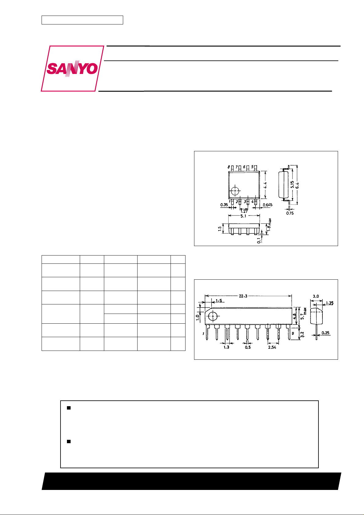
Package Dimensions
unit : mm
3032B-MFP8
[LA6458M]
SANYO : MFP8
unit : mm
3017C-SIP9
[LA6458S]
SANYO : SIP9
Ordering number: EN911D
Monolithic Linear IC
LA6458M, 6458S
Any and all SANYO products described or contained herein do not have specifications that can handle
applications that require extremely high levels of reliability, such as life-support systems, aircraft’s
control systems, or other applications whose failure can be reasonably expected to result in serious
physical and/or material damage. Consult with your SANYO representative nearest you before using
any SANYO products described or contained herein in such applications.
SANYO assumes no responsibility for equipment failures that result from using products at values that
exceed, even momentarily, rated values (such as maximum ratings, operating condition ranges, or other
parameters) listed in products specifications of any and all SANYO products described or contained
herein.
SANYO Electric Co.,Ltd. Semiconductor Bussiness Headquarters
TOKYO OFFICE Tokyo Bldg., 1-10, 1 Chome, Ueno, Taito-ku, TOKYO, 110-8534 JAPAN
63096HA(II)/1100YT/8237KI/8064KI/O064KI,TS No.911-1/5
Operating Characteristics at Ta = 25°C, V
CC
=15V,V
EE
= –15 V
Parameter Symbol Conditions min typ max Unit
Input offset voltage V
IO
R
S
=10kΩ 0.5 6 mV
Input offset current I
IO
5 200 nA
Input bias current I
B
60 500 nA
Common-mode input voltage V
ICM
±12 ±14 V
Common-mode rejection ratio CMR 70 90 dB
Voltage gain VG
O
R
L
^ 2kΩ,V
O
=±10 V 86 100 dB
Maximum output voltage
V
O
(1) R
L
^ 10 kΩ±12 ±14 V
V
O
(2) R
L
^ 2kΩ±10 ±13 V
Slew rate SR
LA6458M: VG = 0, R
L
^ 2kΩ 1.0 V/µs
LA6458S: VG = 0, R
L
^ 2kΩ 1.1 V/µs
Equivalent input noise voltage V
NI
LA6458M: R
S
=1kΩ, B.P.F. = 10 Hz to 30 kHz 1.6 µV
LA6458S: R
S
=1kΩ, B.P.F. = 10 Hz to 30 kHz 1.7 µV
Current drain I
CC
3.5 6 mA
Supply voltage rejection SVR R
S
% 10 kΩ 30 150 µV/V
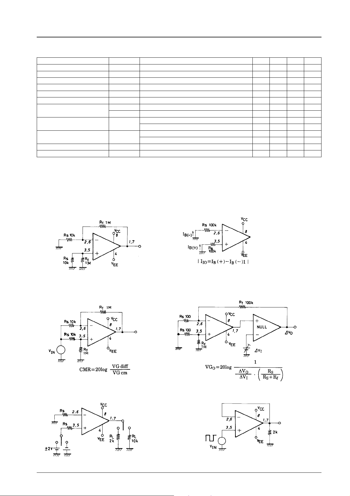
Test Circuits
(Pin assignment : SIP/MFP package)
1. V
IO
, SVR
2. I
IO
,I
B
3. V
ICM
, CMR
4. VG
O
5. V
O
6. SR
Unit (resistance: Ω)
LA6458M, 6458S
No.911-2/5
 Loading...