SANYO LA4278 Datasheet

Ordering number: ENN7096
Monolithic Linear IC
LA4278
10 W 2-Channel Power Amplifier
Overview |
Package Dimensions |
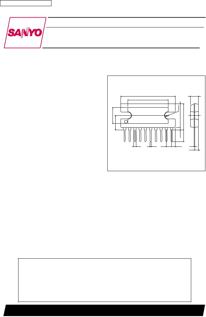
The LA4278 is a 10 W 2-channel power amplifier intended for televisions.
This IC has a series of pin compatible monaural and 2- channel power amplifiers, thus allows the end product to use a common circuit boad.
Features
•Television audio output.
•Pin compatible with the LA4266 (3 W)/LA4267 (5 W)/ 4268 (10 W) and the LA4276 (3 W × 2)/4277(5 W × 2).
•Package: SIP-10H (2.54 mm pitch, straight pins).
•Thermal protection circuit and overvoltage protection circuit on chip.
•Output power: 10 W × 2(VCC = 28 V/RL = 8 Ω).
Specifications
Maximum Ratings at Ta = 25°C
unit: mm
3024A-SIP10H |
|
|
|
|
|
|
|
|
[LA4278] |
|
|
|
|
|
|
27.0 |
|
|
|
4.0 |
|
|
20.0 |
|
|
|
|
|
|
|
|
R1.7 |
|
|
8.4 |
7.0 |
|
|
11.8 |
13.2max |
|
|
|
|
|
1.0 min |
6.0 |
|
|
1 |
|
|
10 |
|
|
|
1.4 |
0.5 |
2.54 |
2.07 |
0.4 |
|
|
|
|
|
|
|
2.0 |
|
|
|
|
SANYO: SIP10H |
||
Parameter |
Symbol |
Conditions |
Ratings |
Unit |
Maximum supply voltage |
VCC |
Rg = 0 |
35 |
V |
Maximum output current |
IO peak |
Per channel |
2.5 |
A |
Allowable power dissipation |
Pd max |
Infinite heat sink |
25.0 |
W |
Thermal resistance |
θ j-c |
|
3.0 |
°C/W |
Operating temperature |
Topr |
|
–20 to +75 |
°C |
Storage temperature |
Tstg |
|
–40 to +150 |
°C |
Operating Conditions at Ta = 25°C
Parameter |
Symbol |
Conditions |
Ratings |
Unit |
Recommended supply voltage |
VCC |
|
28 |
V |
Load resistance |
RL |
|
8 |
Ω |
Operating supply voltage range |
VCC op |
Range does not exceed Pd |
10 to 34 |
V |
|
|
|
|
|
 Any and all SANYO products described or contained herein do not have specifications that can handle applications that require extremely high levels of reliability, such as life-support systems, aircraft’s control systems, or other applications whose failure can be reasonably expected to result in serious physical and/or material damage. Consult with your SANYO representative nearest you before using any SANYO products described or contained herein in such applications.
 SANYO assumes no responsibility for equipment failures that result from using products at values that exceed, even momentarily, rated values (such as maximum ratings, operating condition ranges, or other parameters) listed in products specifications of any and all SANYO products described or contained herein.
SANYO Electric Co.,Ltd. Semiconductor Company
TOKYO OFFICE Tokyo Bldg., 1-10, 1 Chome, Ueno, Taito-ku, TOKYO, 110-8534 JAPAN
41202RM (II) No. 7096-1/6

LA4278
Operating Characteristics at Ta = 25°C, VCC = 28 V, RL = 8 Ω, f = 1 kHz, Rg = 600 Ω, with specified board, in specified circuit
Parameter |
Symbol |
Conditions |
|
|
Ratings |
|
Unit |
|
min |
typ |
max |
||||
|
|
|
|
|
|||
Quiescent current |
ICCO |
Rg = 0 |
|
55 |
80 |
mA |
|
Voltage gain |
VG |
VO = 0 dBm |
38 |
40 |
42 |
dB |
|
Total harmonic distortion |
THD |
PO = 0.5 W |
|
0.1 |
0.8 |
% |
|
Output noise voltage |
VNO |
Rg = 10 kΩ, BPF = 20 Hz to 20 kHz |
|
0.25 |
1.0 |
mV |
|
Output power |
PO |
THD = 10 % |
8.0 |
10 |
|
W |
|
Ripple rejection |
SVRR |
Rg = 0, fr = 100 Hz, Vr = 0.5 Vrms |
45 |
55 |
|
dB |
|
Crosstalk |
CT |
Rg = 10 kΩ, VO = 0 dBm |
40 |
55 |
|
dB |
|
Pd max – Ta
W |
28 |
|
|
|
|
|
|
|
|
|
|
Infinite heat sink |
|
|
|
AI heat sink |
|
||||
— |
|
25 |
|
|
|
|||||
25 |
|
|
|
|
|
Mounting |
|
|||
max |
24 |
|
|
|
|
|
|
torque 39N¥cm |
|
|
|
|
|
|
|
|
|
Flat washer |
|
||
|
|
|
|
|
|
|
Silicone grease |
|
||
Pd |
|
|
|
|
|
|
|
|
||
20 |
|
|
|
|
|
|
applied |
|
|
|
dissipation, |
16 |
|
|
|
|
|
|
|
|
|
12.5 |
100 × 100 × 1.5 mm3 |
|
|
|
|
|
||||
12 |
|
|
|
|
|
|
|
|
|
|
power |
|
|
|
|
|
|
|
|
|
|
8 |
50 × 50 × 1.5 mm3 |
7.5 |
|
|
|
|
|
|||
|
|
|
|
|
|
|||||
Allowable |
7 |
|
|
|
|
|
|
|
|
|
|
No heat sink |
|
4.2 |
|
|
|
|
|
||
4 |
|
|
|
|
|
|
|
|||
3.2 |
|
|
|
1.92 |
|
|
|
|
|
|
0 |
|
|
|
|
|
|
|
|
|
|
|
0 |
20 |
40 |
60 |
80 |
|
|
|
|
|
|
--20 |
100 |
120 |
140 |
160 |
|||||
Ambient temperature, Ta — ¡C ILA00880
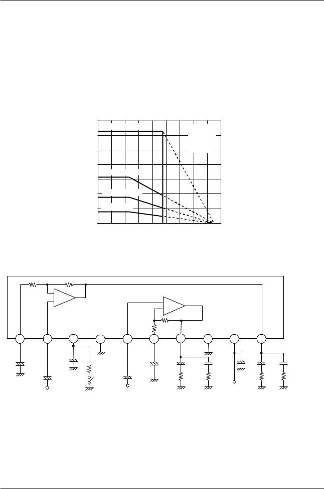
Pin Assignment and Equivalent Circuit Diagram
300 Ω |
|
|
30 kΩ |
|
|
|
|
|
|
|
|
|
|
|
|
|
|
|
|
|
|
|
|
|
300 Ω |
30 kΩ |
|
|
|
|
|
|
|
|
|
NF1 |
IN1 |
|
|
Filter |
PRE GND |
IN2 |
NF2 |
OUT2 |
Power GND |
VCC |
|
OUT1 |
|
|
|||
1 |
2 |
|
|
3 |
4 |
5 |
|
6 |
7 |
|
8 |
9 |
|
10 |
|
|
|
+ |
|
|
µF |
+ |
|
|
|
+ |
+ |
µF |
µF |
|
+ |
+ |
µF |
|
µF |
|
|
|
|
|
|
|
|
||||||||||
|
|
|
|
|
|
|
|
|
|
F |
|
|
|||||
C1 100Fµ |
|
C3 |
100 |
|
|
+ |
|
C5 100Fµ |
C6 |
|
C7 |
|
C8 1000µ |
C9 |
|
C10 |
0.1 |
|
|
|
|
|
RL |
R2 1.0 Ω0.1 |
|
RL |
|
|
|||||||
|
|
|
|
|
|
|
|
|
|||||||||
C2 4.7Fµ |
|
|
R1 750Ω |
C4 4.7Fµ |
|
|
|
1000 |
R3 1.0Ω |
||||||||
|
|
|
|
1000 |
|
|
|||||||||||
* For Muting, add a resistor between pin 3 and GND. 750 Ω for the LA4266/67/68, 200 Ω for the LA4276/77.
No. 7096-2/6
 Loading...