


 Loading...
User Manual
MODEL QS434
QS464
QS408
QS206
QS4474
H.264 NETWORK DVR
QS Series
Thank You for Choosing a Q-See Product!
All of our products are backed by a conditional service warranty covering all hardware for 12 months from the date of purchase. Additionally, our products also come with a free exchange policy that covers all manufacturing defects for one month from the date of purchase. Permanent upgrading service is provided for the software and is available at www.Q-See.com.
Be certain to make the most of your warranty by completing the registration form online. In addition to warranty and technical support benefits, you’ll receive notifications of product updates along with free downloadable firmware updates for your DVR. Register today at www.Q-See.com!
Please see the back of this manual for exclusions.
© 2011 Q-See. Reproduction in whole or in part without written permission is prohibited. All rights reserved. This manual and software and hardware described herein, in whole or in part, may not be reproduced, translated, or reduced to any machine-readable form without prior
written approval.
Trademarks: All brand names and products are trademarks or registered trademarks of their respective owners.
Q-See is a registered trademark of DPS, Inc.
Disclaimer: The information in this document is subject to change without notice. The manufacturer makes no representations or warranties, either express or implied, of any kind with respect to completeness of its contents.
Manufacturer shall not be liable for any damages whatsoever from misuse of this product.
2
About this Manual
This manual is written for the QS series of DVRs and was accurate at the time it was completed. However, because of our ongoing effort to constantly improve our products, additional features and functions may have been added since that time and on-screen displays may change. We encourage you to visit our website at www.Q-see.com to check for the latest firmware updates and product announcements.
Throughout the manual we have highlighted warnings and other important information that will assist you in operating your new system in a safe and trouble-free manner. Please take the time to read and follow all instructions and pay attention to alerts as shown below:
IMPORTANT! Red boxes with this icon indicate warnings. To prevent possible injury or damage to the product, read all warnings before use.
NOTE! Text in blue boxes with the Information icon offer additional guidance and explanations about how to make the most out of your system.
Rev. 2.2 8/1/11
3

TABLE OF CONTENTS
1. INTRODUCTION |
7 |
|
Features and Specifications |
8 |
|
2. INSTALLATION AND CONNECTION |
10 |
|
QS206 |
12 |
|
QS408 |
14 |
|
QS434 |
16 |
|
QS464 |
18 |
|
QS4474 |
20 |
|
3. CONTROLS |
22 |
|
3.1 |
Mouse Control |
22 |
Virtual Keyboard |
23 |
|
3.2 |
Remote Control |
24 |
4. BASIC OPERATION |
26 |
|
4.1 |
Power On/Off |
26 |
Standby Mode |
26 |
|
LCD On/Off |
26 |
|
Shutdown |
26 |
|
4.2 |
Shortcut Menu |
27 |
4.3 |
System Login |
27 |
4.4 Main Menu |
28 |
|
4.5 |
Basic Settings |
29 |
Language |
29 |
|
Date/Time |
30 |
|
Password |
31 |
|
Display |
32 |
|
Video/Audio |
33 |
|
4.6 Hard Drive (HDD) Management |
34 |
|
Formatting the Internal Hard Drive |
34 |
|
4.7 |
Playback |
35 |
Video Search |
35 |
|
File List |
36 |
|
Using the On-Screen Playback Controls |
37 |
|
4.8 Backup |
38 |
|
Using the Playback Software |
39 |
|
5. RECORDING |
42 |
|
5.1 |
Recording Configuration |
42 |
5.2 |
Recording Schedule |
43 |
5.3 |
Mask Field |
44 |
5.4 |
Motion Detect |
45 |
6. ADVANCED FEATURES |
46 |
|
6.1 |
Alarm |
47 |
6.2 |
Email Setup |
48 |
6.3 |
System Info |
49 |
6.4 |
System |
49 |
Restoring Factory Settings |
50 |
|
Restarting the DVR (Soft-Reset) |
50 |
|
Upgrading the Firmware |
50 |
|
6.5 |
Pan-Tilt-Zoom Cameras (PTZ) |
51 |
7. HARD DRIVE INSTALLATION |
52 |
|
APPENDIX |
53 |
|
Product Specifications |
53 |
|
Frequently Asked Questions |
55 |
|
Q-SEE PRODUCT WARRANTY |
59 |
|
Questions or Comments? Contact Us |
60 |
|
4 |
5 |

INTRODUCTION |
CHAPTER 1 |
To prevent damage to your Q-See product or injury to yourself or to others, read and understand the following safety precautions in their entirety before installing or using this equipment. Keep these safety instructions where all those who use the product will read them.
WARNING! ELECTRIC SHOCK RISK!
nCheck the unit and any accessories included in the package immediately after opening. If items are missing or damaged, repackage and return to the point of purchase.
nUse the proper power source. Only use the power adapter supplied with your system. Do not use this product with a power source that applies more than the specified voltage (100240V AC).
nNever insert anything metallic into the DVR. Inserting anything into the DVR or its case can be a source of dangerous electric shock.
nDo not operate in dusty areas.
nDo not expose this product to rain or use near water. If this product accidentally gets wet, unplug it and contact an authorized dealer immediately.
nKeep product surfaces clean and dry. To clean the outside case of the DVR, gently wipe using a lightly dampened cloth (only use water, do not use solvents).
nDo not operate this DVR without the cover securely in place. Do not attempt to do any repairs to the DVR yourself. If there are unusual sounds or smells coming from the DVR, unplug it immediately and contact Q-See technical support. Under no circumstances should the cover be removed while the device is connected to a power source. You should only remove the cover to install/replace the hard disk drive (See Chapter 7) or replace the standard 3v lithium cell battery on the motherboard. These are the only user serviceable parts. You may need to replace the battery if the internal clock resets itself after a power outage
nHandle DVR box carefully. If you accidentally drop your DVR on any hard surface, it may cause a malfunction. If the DVR doesn’t work properly due to physical damage, contact an authorized dealer for repair or exchange.
nMake sure there is proper air circulation around the unit. This DVR system uses a hard drive for video storage which generates heat during operation. Do not block air holes located on the bottom, top, sides and back of the DVR as they are designed to keep the system cool while running. Install or place this product in an area where there is ample air circulation.
nProvide proper ventilation. This DVR has a built-in fan that properly ventilates the system. Do not cover or impede this fan.
6 |
7 |

FEATURES AND SPECIFICATIONS
This product offers the following features:
Smartphone Compatible
Access live footage directly from your iPhone, iPad or smartphones running Windows Mobile, Android, Symbian or BlackBerry operating systems. Your DVR can also be set to e-mail your hand held-device whenever specific activity occurs, such as motion detection.
View Your Video Feed Online with No Extra Service Fees
View your DVR’s live or recorded video footage on any Internet accessible computer with Internet Explorer, Mozilla Firefox and Google Chrome (using IE plug-in).
Stay Notified with Customizable Email Alerts
Set your system up to notify you when an event has occurred at the location you are monitoring. Notification alerts can easily be adjusted to your specifications.
Advanced Motion Detection Activated Recording
Advanced motion detection settings ensure that false alarms are not triggered. The easy to use motion detect set up screen allows you to mask out certain areas which experience heavy movement in order to avoid false alarms and avoid unnecessary record triggering.
Multiple Backup Options
A built-in USB port gives you the option of backing up and transferring your video footage using a flash drive or external USB hard drive. You can also connect to an external CD/ DVD writer to burn your file footage right onto a compact disc or DVD disc. Files can also be accessed from your DVR system to a remote computer location by logging on remotely.
Connect to a TV or PC Monitor Easily
This system comes with both a VGA and BNC out port to allow you to connect to a TV or computer monitor for viewing purposes.
User-Friendly LCD Control Functions
Front panel button control allows instant booting up and system standby at the press of a button. LCD monitor can be set to go into energy efficient stand-by mode.
Included Mouse and Remote Control
In addition to front panel button controls, system can also be booted up and put into standby mode using the included remote control or mouse.
Storage Function
Encrypted file format to ensure data security and avoid vicious data modification.
Compression Format
Supports multiple-channel audio and video. Independent hardware decodes the audio and video signal from each channel to maintain video and audio synchronization.
Audio Recording
Up to eight channels of audio recording capability depending on model.
24/7 Scheduled Recording
Choose which days of the week and hours of the day you want to set your DVR to record or not record.
Multiple Playback Options and Advanced Search Functions
Supports real-time recording on each channel independently. Search through recorded files while you are playing live footage, monitoring through a remote location using a supported internet browsing application and backing up system files. A variety of playback modes include: slow play, fast play, and backward play.
Network Monitoring
Supports network remote real-time monitoring (available bandwidth permitting), remote record search and remote PTZ control.
Alarm Activation Function
Several relay alarm outputs enable you to pair your system with an on-site alarm system.
Communication Ports
sRS485 port can be used for PTZ camera control.
sStandard Ethernet port allows you to access the DVR from a network or the Internet.
PTZ camera control
sSupports PTZ decoder via RS485.
sSupports the PelcoD and PelcoP protocols.
NOTE! Depending on your point of purchase, your DVR may have the hard disk drive already installed. If your drive was packaged separately, or if you wish to upgrade your installed drive up to a 1 Terabyte (QS434 and QS408) or a 2 Terabyte (QS206) drive, please see Chapter 7 at the back of this manual which covers installing the drive.
8 |
9 |
INSTALLATION AND |
CHAPTER 2 |
CONNECTION |
|
Please note that it is important to keep in mind common safety guidelines when installing your DVR or connecting additional devices – including turning off and unplugging your DVR before installing internal components.
POWER
The DVR’s power supply plugs into the DC power socket on the back of the DVR. It is absolutely essential that you only use the power supply that came with the DVR to ensure proper operation and to avoid damage.
We also recommend that you use an uninterrupted power supply (UPS) so that the system will continue to operate in the event of a power loss. In addition, you should connect the DVR into a UL-1449 rated surge protector. It should have a joule rating of at least 400, a response time of 10 nanoseconds or less and a clamping voltage of no more than 330 volts.
Some models feature a power switch on the rear panel, while all models have a soft power switch on the front. For those models with a rear panel power switch, it must be flipped to the On position to start the DVR. The other models will power up as soon as they are plugged in.
When shutting down the DVR, it is essential that you do so by pressing and holding the soft power switch on the front until the DVR enters standby mode. Once the display goes blank, you may either flip the rear power switch to Off or unplug the DVR.
If you wish to restart the DVR from standby mode, then you may do so by pressing and holding the soft power switch again.
USB PORTS
With the exception of the Model QS464, the port on the front of the DVR is reserved for external USB drives - whether to back up saved files or to install a firmware upgrade. The USB mouse should be plugged into the port on the back of the DVR. The QS464 has dual USB ports on the front panel with the upper port used for the external drive and the lower port available for use by the mouse. The QS464 features a third USB port on the rear panel for use by the mouse should you prefer.
VIDEO DISPLAY
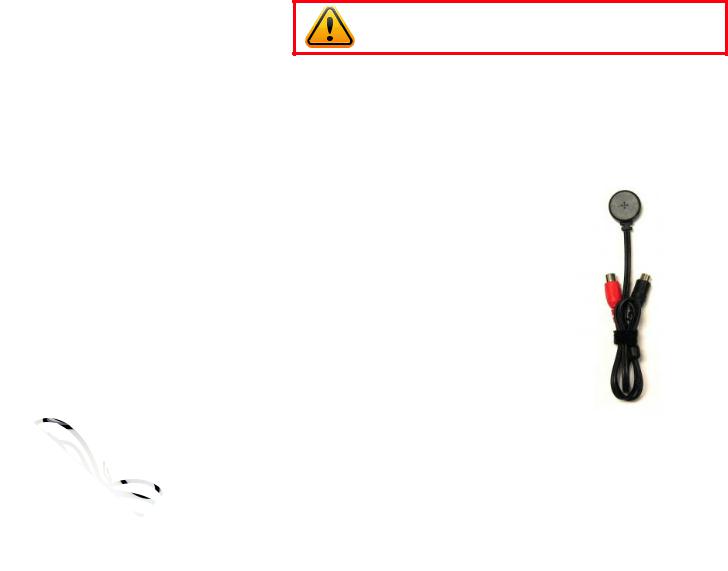
The DVR can output video to either a standard VGA monitor or television. The monitor is connected via a VGA monitor cable (not included) to the VGA port on the rear of the DVR. The QS4474 does not include a VGA port. The television is connected to the BNC Video Out port on the DVR’s back panel through the use of the included BNC (Male)
to RCA (Female) adapter cable (Picture 2-1) PICTURE 2-1 which plugs into the RCA Video In port on
the back of the television.
Both displays may be used at the same time, however they will both show the same images and they cannot be combined. The mouse cursor will only appear on one screen at a time and this may be selected by rolling the mouse scroll wheel forward (VGA) or backwards (television).
The second display may be used as a “Spot” monitor in a location away from the DVR to allow another person to view, but not control, the system.
IMPORTANT! The default resolution of this DVR is 1024 x 768 pixels. Some monitors smaller than 19” may not display video properly.
AUDIO
Depending on the model of your DVR, you can record one or more channels of audio to accompany your video recording. When there are an equal number of video and audio inputs, the audio will be recorded on the corresponding channel. On DVRs with only one or two audio inputs, the audio signal will be recorded on the first channel(s) so you should connect an audio-capable camera to those channels. Likewise, if you are co-locating a microphone to capture audio to accompany a camera’s video signal, then the camera should be connected into the first channel or channels.
Also depending upon your model, the audio connection ports will either be BNC (like the video ports) or RCA. Microphones, such as Q-See’s QSPMIC (Picture 2-2) generally have RCA connectors. If your DVR has RCA audio inputs, then these will connect directly to the DVR. For those models with the BNC connectors, you will need to use a BNC (Male to RCA (Female) adapter cable shown in
Picture 2-1.
For output, most readily available speakers, such as those used in audio systems will have an RCA connector. The QS4474 has a built-in internal speaker.
The connections and ports of the various models are presented on the following pages.
10 |
11 |
QS206
FRONT PANEL
|
|
|
|
|
|
|
|
|
|
|
|
|
|
|
|
|
|
|
|
|
|
|
|
|
|
|
|
|
|
|
|
|
||||||||
1 |
2 |
|
|
|
|
3 |
|
|
4 |
|
|
|
|
5 |
|
|
6 |
|
||||||||||||||||||||||
|
|
|
|
|
|
|
|
|
|
|
|
|
|
|
|
|
|
|
|
|
|
|
|
|
|
|
|
|
|
|
|
|
|
|
|
|
|
|
|
|
|
|
|
|
|
|
1 |
2 |
3 |
4 |
5 |
|
|
|
|
|
|
|
|
|
|
|
|
|
|
|
|
|
|
|
|
|
|
|
|
|
|
|
|||
|
|
|
MENU |
|
|
|
|
|
|
|
HDD REC |
ALM FULL |
NET |
|
|
|
|
|
|
|||||||||||||||||||||
|
|
|
|
|
|
|
|
|
|
|
|
|
|
|
|
|
|
|
||||||||||||||||||||||
|
|
|
EXIT |
6 |
7 |
8 |
9 |
0 |
|
|
OK |
|
|
|
|
|
|
|
|
|
|
|
|
|
|
|
|
|
|
|
|
|||||||||
|
|
|
|
|
|
|
|
|
|
|
|
|
|
|
|
|
|
|
|
|
|
|
|
|
||||||||||||||||
QS206 |
|
16CH H.264 Digital Video Recorder |
|
|
|
|
|
|
|
|
|
|
|
|
|
|
|
|
|
|
|
|
|
|
|
|
|
|
|
|
||||||||||
|
|
|
|
|
|
|
|
|
|
|
|
|
|
|
|
|
|
|
|
|
|
|
|
|
|
|
|
|
|
|
||||||||||
|
|
|
|
|
|
|
|
|
|
|
|
|
|
|
|
|
|
|
|
|
|
|
|
|
|
|
|
|
|
|
||||||||||
|
|
|
|
|
|
|
|
|
|
|
|
|
|
|
|
|
|
|
|
|
|
|
|
|
|
|
|
|
|
|
||||||||||
|
|
|
|
|
|
|
|
|
|
|
|
|
|
|
|
|
|
|
|
|
|
|
|
|
|
|
|
|
|
|
|
|||||||||
|
|
|
|
|
|
|
|
|
|
|
|
|
|
7 |
|
|
|
|
8 |
|
|
|
|
|
9 |
|
||||||||||||||
|
|
|
|
|
|
|
|
|
|
|
|
|
|
|
|
|
|
|
|
|
|
|
|
|
|
|
|
|
|
|
|
|
|
|
|
|
|
|
|
|
Item # |
Name/ Symbol |
|
|
Description |
|
|
|
|
|
|
|
|
|
|
|
|
|
|
|
|
|
|
|
|
|
|
|
|
|
|
|
|
||||||||
|
|
|
|
|
|
|
|
|
|
|
|
|
|
|
|
|
|
|
|
|
|
|
|
|
|
|
|
|
|
|
|
|
|
|
|
|
|
|||
1 |
|
STANDBY |
|
|
Press to set the system in standby mode. Press again to wake. |
|||||||||||||||||||||||||||||||||||
|
|
|
|
|
|
|
|
|
|
|
|
|
|
|
|
|
|
|
|
|
|
|
|
|
|
|
|
|
|
|
|
|
|
|
|
|
|
|||
2 |
|
MENU/EXIT |
|
|
Press to open/close the main menu. |
|
|
|
|
|
|
|
|
|||||||||||||||||||||||||||
|
|
|
|
|
|
|
|
|
|
|
|
|
|
|
|
|
|
|
|
|
|
|
|
|
|
|
|
|
|
|
|
|
|
|
|
|
|
|||
3 |
|
CHANNEL/ |
|
|
Press the number buttons to view the selected channel full- |
|||||||||||||||||||||||||||||||||||
|
|
NUMBERS |
|
|
screen; press buttons 1-0 to input passwords and user IDs. |
|||||||||||||||||||||||||||||||||||
|
|
|
|
|
|
|
|
|
|
|
|
|
|
|
|
|
|
|
|
|
|
|
|
|
|
|
|
|
|
|
|
|
|
|
|
|
|
|
|
|
4 |
|
|
|
|
|
|
|
|
|
▲ |
|
Press to move cursor up; in PTZ mode, press to pan |
||||||||||||||||||||||||||||
|
|
|
|
|
|
|
|
|
|
|
camera up. |
|
|
|
|
|
|
|
|
|
|
|
|
|
|
|
||||||||||||||
|
|
|
|
|
|
|
|
|
|
▼ |
|
Press to move cursor down; in PTZ mode, press to |
||||||||||||||||||||||||||||
|
|
NAVIGATION |
|
|
|
|
pan camera down. |
|
|
|
|
|
|
|
|
|
|
|
|
|
|
|
||||||||||||||||||
|
|
|
|
|
◄ |
|
Press to move cursor left; in PTZ mode, press to pan |
|||||||||||||||||||||||||||||||||
|
|
|
|
|
|
|
|
|
|
|
||||||||||||||||||||||||||||||
|
|
|
|
|
|
|
|
|
|
|
camera left. |
|
|
|
|
|
|
|
|
|
|
|
|
|
|
|
||||||||||||||
►Press to move cursor right; in PTZ mode, press to pan camera right.
5 |
LED |
Shows status of hard drive, recording, alarm, HDD full and |
|
|
INDICATORS |
network. |
|
|
|
|
|
6 |
IR SENSOR |
IR Receiver for remote control. |
|
|
|
|
|
7 |
|
In menus, press to confirm selections; in PTZ mode, press to |
|
|
OK |
change the navigation buttons to control a connected PTZ |
|
|
|
camera (not included) |
|
|
|
|
|
8 |
|
◄◄ |
Increase reverse playback speed 1X, 2X, 4X. |
|
|
n/► |
Press to freeze playback to one frame, then press |
|
DURING |
again to advance frame-by-frame. |
|
|
► |
Press to start playback |
|
|
PLAYBACK |
||
|
|
||
|
PRESS: |
|
|
|
►►| |
Press to slow playback speed by 1/2, 1/4, 1/8. |
|
|
|
||
|
|
►► |
Press to increase forward playback speed 1X, 2X, |
|
|
4X. |
|
9 |
|
USB |
Connect a USB flash drive for data backup and |
|
|
|
firmware upgrades |
|
|
|
|
REAR PANEL
1
|
|
|
|
|
|
|
VIDEO IN |
|
|
|
|
|
|
||
1 |
2 |
3 |
4 |
5 |
6 |
|
|
7 |
8 |
9 |
10 |
11 |
12 |
13 |
14 |
|
|
|
|
|
|
|
|
|
|
AUDIO IN |
AUDIO |
CVBS OUT |
16 |
15 |
|
DC +12V |
VGA |
RJ45 |
USB |
1 2 3 4 |
GND5 COM1 NO1 COM2 NO2 GND |
485A-2 |
485B-2 |
GND 485A-1 485B-1 |
GND +12V GND |
|
|
||||
|
|
OUT |
|
|
|
|
|||||||||
IN |
|
|
|
ALM IN |
|
|
|
|
|
||||||
2 |
3 |
4 |
5 |
|
6 |
|
|
|
|
7 |
8 |
|
9 |
|
|
Item # |
Connector |
Description |
|
|
|
|
|
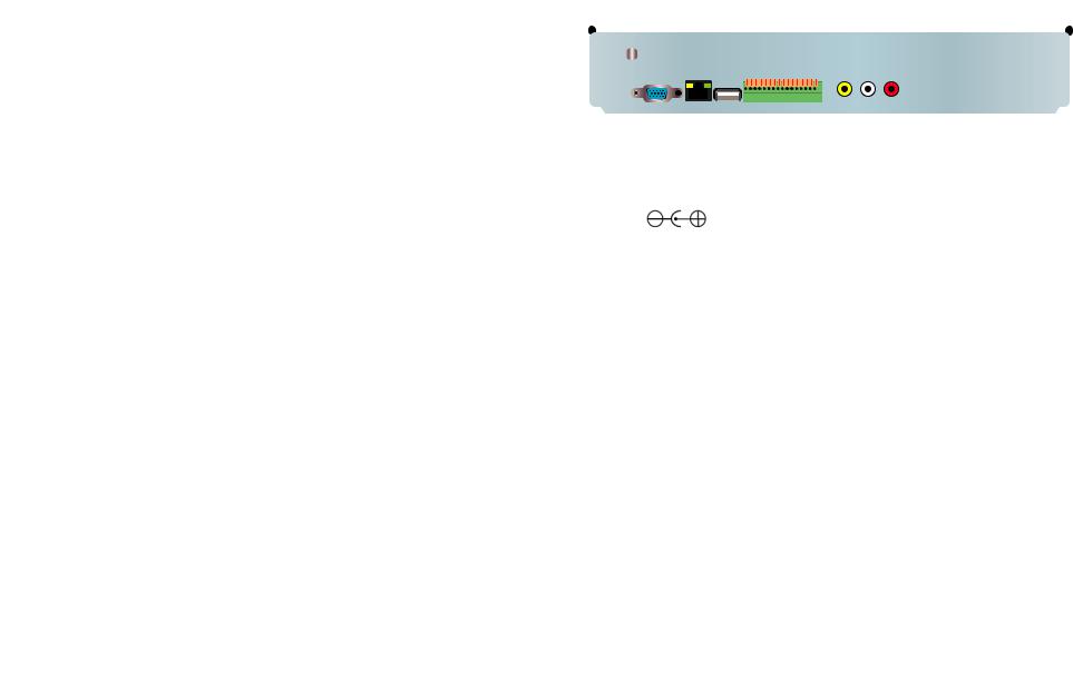
1 |
VIDEO IN |
Video input for connecting analog video signal input (BNC) |
|
|
|
|
|
2 |
|
DC 12V/3A Power Connection |
|
|
|
|
|
3 |
VGA OUTPUT |
To connect to VGA monitor |
|
|
|
|
|
4 |
NETWORK |
For connecting Ethernet cable |
|
|
|
|
|
5 |
USB |
Mouse port |
|
|
|
|
|
|
ALARM INPUT |
8 I/O Alarm input |
|
|
|
|
|
|
ALARM |
I/O Output for alarm |
|
|
OUTPUT |
||
6 |
|
||
|
|
||
RS485 |
RS485 for connecting PTZ |
||
|
|||
|
|
|
|
|
+12V |
Power supply for DC relay, the current is 100MA (to prevent |
|
|
short circuits) |
||
|
|
||
|
|
|
|
7 |
AUDIO IN |
Audio input for connecting audio signal (2 feeds) |
|
|
|
|
|
8 |
AUDIO |
For connection to amplified speaker |
|
OUTPUT |
|||
|
|
||
|
|
|
|
9 |
VIDEO OUT |
Video output for connecting TV (BNC) |
|
|
|
|
12 |
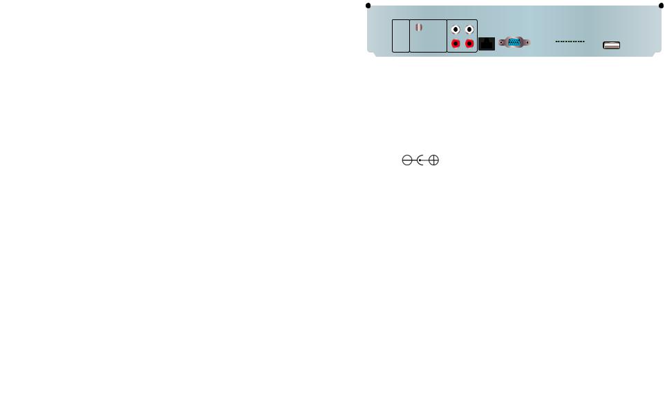
13 |
QS408
FRONT PANEL |
REAR PANEL |
1 |
2 |
3 |
4 |
5 |
1 |
2 |
3 |
4 |
QS408 |
HDD |
REC |
ALM |
FULL |
NET |
ON/OFF |
|
|
AUDIO IN |
|
AUDIO |
|
|
|
|
|
|
|
|
|
|
||||
|
1 |
2 |
|
3 |
|
|
|
|
1 |
3 |
5 |
7 |
|
|
|
|
|
|
USB |
|
|
|
|||
|
|
|
|
|
|
|
|
|
|
|
|
|
MENU |
4 |
5 |
|
6 |
OK |
|
|
|
|
|
|
|
EXIT |
|
- |
+ |
|
|
|
|
OUT |
||||
|
|
|
|
|
|
|
|
|
|
|
||
|
7 |
8 |
|
9 |
|
0 |
|
|
|
|
|
|
|
|
|
|
|
|
|
|
|
2 |
4 |
6 |
8 |
|
|
|
|
|
|
DC +12V |
RJ45 |
VGA |
|
|
VIDEO |
|
|
|
|
|
|
|
|
IN |
|
|
|
|
|
6 |
|
7 |
|
|
8 |
9 |
6 |
7 |
8 |
|
|
9 |
|
5 |
|
|
|
|
|
|
|
VIDEO IN |
|
|
|
|
|
|
1 |
3 |
5 |
7 |
|
|
|
|
2 |
4 |
6 |
8 |
GND 485B |
485A |
GND NO COM GND |
1 2 3 4 5 6 7 8 |
|
|
|
+12V |
ALARM IN |
10
Item # |
Name/ Symbol |
Description |
|
|
|
|
|
1 |
STANDBY |
Press to set the system in standby mode. Press again to wake. |
|
|
|
|
|
2 |
LED |
Shows status of hard drive, recording, alarm, HDD full and |
|
|
INDICATORS |
network. |
|
3 |
|
▲ |
Press to move cursor up; in PTZ mode, press to pan |
|
|
camera up. |
|
|
|
▼ |
Press to move cursor down; in PTZ mode, press to |
|
NAVIGATION |
pan camera down. |
|
|
◄ |
Press to move cursor left; in PTZ mode, press to pan |
|
|
|
||
|
|
camera left. |
|
|
|
► |
Press to move cursor right; in PTZ mode, press to |
|
|
pan camera right. |
|
4 |
|
◄◄ |
Increase reverse playback speed 1X, 2X, 4X. |
|
|
n/► |
Press to freeze playback to one frame, then press |
|
DURING |
again to advance frame-by-frame. |
|
|
► |
Press to start playback |
|
|
PLAYBACK |
||
|
|
||
|
PRESS: |
|
|
|
►►| |
Press to slow playback speed by 1/2, 1/4, 1/8. |
|
|
|
||
|
|
►► |
4X.Press to increase forward playback speed 1X, 2X, |
5 |
IR SENSOR |
IR Receiver for remote control. |
|
|
|
|
|
6 |
MENU/EXIT |
Press to open/close the main menu. |
|
|
|
|
|
7 |
CHANNEL/ |
Press buttons 1-8 to view that channel full-screen |
|
|
Press buttons 1-0 (“0” is located next to the playback buttons) to |
||
|
NUMBERS |
||
|
input passwords and user IDs. |
||
|
|
||
|
|
|
|
7 |
|
In menus, press to confirm selections; in PTZ mode, press to |
|
|
OK |
change the navigation buttons to control a connected PTZ |
|
|
|
camera (not included) |
|
|
|
|
|
9 |
|
USB |
Connect a USB flash drive for data backup and |
|
|
|
firmware upgrades |
|
|
|
|
Item # |
Connector |
Description |
|
|
|
|
|
1 |
Power Switch |
Power On/Off |
|
|
|
|
|
2 |
USB |
Mouse port |
|
|
|
|
|
3 |
AUDIO IN |
Audio input for connecting audio signal (8 feeds) |
|
|
|
|
|
4 |
AUDIO |
For connection to amplified speaker |
|
OUTPUT |
|||
|
|
||
|
|
|
|
5 |
VIDEO IN |
Video input for connecting analog video signal input (BNC) |
|
|
|
|
|
6 |
|
DC 12V/3A Power Connection |
|
|
|
|
|
7 |
NETWORK |
For connecting Ethernet cable |
|
|
|
|
|
8 |
VGA OUTPUT |
To connect to VGA monitor |
|
|
|
|
|
9 |
VIDEO OUT |
Video output for connecting TV (BNC) |
|
|
|
|
|
|
ALARM INPUT |
8 I/O Alarm input |
|
|
|
|
|
|
ALARM |
I/O Output for alarm |
|
|
OUTPUT |
||
10 |
|
||
|
|
||
RS485 |
RS485 for connecting PTZ |
||
|
|||
|
|
|
|
|
+12V |
Power supply for DC relay, the current is 100MA (to prevent |
|
|
short circuits) |
||
|
|
||
|
|
|
14 |
15 |
QS434
FRONT PANEL
|
|
|
|
|
|
|
|
|
|
|
|
|
|
|
|
|
|
|
|
|
|
|
|
||||||||||
1 |
2 |
|
|
|
3 |
|
|
|
4 |
|
|
|
|
5 |
|
|
6 |
||||||||||||||||
|
|
|
|
|
|
|
|
|
|
|
|
|
|
|
|
|
|
|
|
|
|
|
|
|
|
|
|
|
|
|
|
|
|
|
|
|
|
|
|
1 |
2 |
3 |
4 |
5 |
|
|
|
|
|
|
|
|
|
|
|
|
|
|
|
|
|
|
|
|
|
|
|
|
|
|
MENU |
|
|
|
|
HDD REC |
ALM FULL |
NET |
|
|
|
|
|||||||||||||||||||
|
|
|
EXIT |
6 |
7 |
8 |
9 |
0 |
|
OK |
|
|
|
|
|
|
|
|
|
|
|
|
|
|
|
|
|
|
|||||
|
|
|
|
|
|
|
|
|
|
|
|
|
|
|
|
|
|
|
|
|
|
|
|||||||||||
|
|
|
|
|
|
|
|
|
|
|
|
|
|
|
|
|
|
|
|
|
|
|
|
|
|
|
|||||||
|
|
|
|
|
|
|
|
|
|
|
|
|
|
|
|
|
|
|
|
|
|
|
|
|
|
|
|
|
|
|
|
|
|
|
|
|
|
|
|
|
|
|
|
|
|
|
|
|
|
|
|
|
|
|
|
|
|
|
|
|
|
|
|
|
|
|
|
|
|
|
|
|
|
|
|
|
|
|
|
|
|
|
|
|
|
|
|
|
|
|
|
|
|
|
|
|
|
|
|
|
|
|
|
|
|
|
|
|
|
|
|
|
|
|
|
|
|
|
|
|
|
|
|
|
|
|
7 |
|
8 |
9 |
|
|||
|
|
|
|
|
|
|
|
|
|
|
Item # |
Name/ Symbol |
Description |
|
|
|
|
|
|
|
|
|
|
|
|
|
|
|
|
|
||
1 |
STANDBY |
Press to set the system in standby mode. Press again to wake. |
||||||||
|
|
|
|
|
|
|
|
|
||
2 |
MENU/EXIT |
Press to open/close the main menu. |
|
|
|
|||||
|
|
|
|
|
|
|
|
|
||
3 |
CHANNEL/ |
Press buttons 1-4 to view that channel full-screen |
|
|
|
|||||
|
NUMBERS |
Press buttons 1-0 to input passwords and user IDs. |
|
|
|
|||||
|
|
|
|
|
|
|
|
|
|
|
4 |
|
▲ |
Press to move cursor up; in PTZ mode, press to pan |
|||||||
|
|
camera up. |
|
|
|
|
|
|||
|
|
▼ |
Press to move cursor down; in PTZ mode, press to |
|||||||
|
NAVIGATION |
pan camera down. |
|
|
|
|
|
|||
|
◄ |
Press to move cursor left; in PTZ mode, press to pan |
||||||||
|
|
|||||||||
|
|
camera left. |
|
|
|
|
|
|||
►Press to move cursor right; in PTZ mode, press to pan camera right.
5 |
LED |
Shows status of hard drive, recording, alarm, HDD full and |
|
|
INDICATORS |
network. |
|
|
|
|
|
6 |
IR SENSOR |
IR Receiver for remote control. |
|
|
|
|
|
7 |
|
In menus, press to confirm selections; in PTZ mode, press to |
|
|
OK |
change the navigation buttons to control a connected PTZ |
|
|
|
camera (not included) |
|
|
|
|
|
8 |
|
◄◄ |
Increase reverse playback speed 1X, 2X, 4X. |
|
|
n/► |
Press to freeze playback to one frame, then press |
|
DURING |
again to advance frame-by-frame. |
|
|
► |
Press to start playback |
|
|
PLAYBACK |
||
|
|
||
|
PRESS: |
|
|
|
►►| |
Press to slow playback speed by 1/2, 1/4, 1/8. |
|
|
|
||
|
|
►► |
Press to increase forward playback speed 1X, 2X, |
|
|
4X. |
|
9 |
|
USB |
Connect a USB flash drive for data backup and |
|
|
|
firmware upgrades |
|
|
|
|
REAR PANEL
|
|
|
|
|
|
|
|
|
|
|
|
|
|
|
|
|
|
|
|
|
|
|
|
|
|
|
|
|
|
|
|
|
|
|
|
|
|
|
|
|
|
|
|
|
|
|
|
|
|
|
|
|
|
||
|
|
|
|
1 |
|
|
2 |
|
|
3 |
|
|
|
|
|
|
|
|
|
|
|
|
|
|
|
|
|
|
|
|
|
|
|
|
|
|
|
|
|
|
|
|
|
|
|
|
|
||||||||
|
|
|
|
AUDIO |
OUT |
VIDEO IN |
|
|
|
AUDIO IN |
|
|
|
|
|
|
|
|
|
|
|
|
|
|
|
|
|
|
|
|
|
|
|
|
|
|
|
|
|
|
|
|
|
|
|
|
|
||||||||
- |
|
+ |
|
|
|
|
|
|
1 |
|
|
3 |
|
1 |
|
|
3 |
|
|
|
|
|
|
VGA |
|
|
|
|
|
|
|
|
|
|
|
|
|
|
|
|
|
|
|
|
|
|
|
|
|
|
|
||||
|
|
|
|
|
|
|
2 |
|
|
4 |
|
2 |
|
|
4 |
|
|
|
|
|
|
|
|
|
|
|
|
|
|
|
|
|
|
|
|
|
|
|
|
|
|
|
|
|
|
|
|
|
|||||||
|
|
|
|
|
|
|
|
|
|
|
|
|
|
|
|
|
|
|
|
|
|
|
|
|
|
|
|
|
|
|
|
|
|
|
|
|
|
|
|
|
|
|
|
|
|||||||||||
|
|
|
|
|
|
|
|
|
|
|
|
|
|
|
|
|
|
|
|
|
|
|
|
|
|
|
|
|
|
|
|
|
|
|
|
|
|
|
|
|
|
|
|
|
|||||||||||
|
|
|
|
|
|
|
|
|
|
|
|
|
|
|
|
|
|
|
|
|
|
|
|
|
|
|
|
|
|
|
|
|
|
|
|
|
|
|
|
|
|
|
|
|
|||||||||||
|
|
|
|
|
|
|
|
|
|
|
|
|
|
|
|
|
|
|
|
|
|
|
|
|
|
|
|
|
|
|
|
|
|
|
|
|
|
|
|
|
|
|
|
|
|||||||||||
|
|
|
|
|
|
|
|
|
|
|
|
|
|
|
|
|
|
|
|
|
|
|
|
|
|
|
|
|
|
|
|
|
|
|
|
|
|
|
|
|
|
|
|
|
|||||||||||
|
|
|
|
|
|
|
|
|
|
|
|
|
|
|
|
|
|
|
|
|
|
|
|
|
|
|
|
|
|
|
|
|
|
|
|
|
|
|
|
|
|
|
|
|
|||||||||||
|
|
|
|
|
|
|
|
|
|
|
|
|
|
|
|
|
|
|
|
|
|
|
|
|
|
|
|
|
|
|
|
|
|
|
|
|
|
|
|
|
|
|
|
|
|||||||||||
|
|
|
|
|
|
|
|
|
|
|
|
|
|
|
|
|
|
|
|
|
|
|
|
|
|
|
|
|
|
|
|
|
|
|
|
|
|
|
|
|
|
|
|
|
|||||||||||
|
|
|
|
|
|
|
|
|
|
|
|
|
|
|
|
|
|
|
|
|
|
|
|
|
|
|
|
|
|
|
|
|
|
|
|
|
|
|
|
|
|
|
|
|
|||||||||||
|
|
|
|
|
|
|
|
|
|
|
|
|
|
|
|
|
|
|
|
|
|
|
|
|
|
|
|
|
|
|
|
|
|
|
|
|
|
|
|
|
|
|
|
|
|
|
|
|
|
|
|||||
|
|
|
|
|
|
|
|
|
|
|
|
|
|
|
|
|
|
|
|
|
|
|
|
|
|
|
|
|
|
|
|
|
|
|
|
|
|
|
|
|
|
|
|
|
|
|
|
|
|
|
|||||
DC |
+19V |
|
|
|
|
|
|
|
|
RJ45 |
|
|
|
|
|
|
|
|
|
|
|
1 2 3 4 |
|
|
USB |
|
|||||||||||||||||||||||||||||
|
|
|
|
|
|
|
|
|
|
|
|
|
|
|
|
|
|
|
|
|
|
|
|
|
|
|
|
|
|
|
|
|
|
|
|
|
|
|
|
|
|
||||||||||||||
|
|
IN |
VIDEO |
OUT |
|
|
|
|
|
|
|
|
|
|
|
|
|
|
|
|
|
|
|
+5V GND 485B 485A GND 1NO |
1COM |
GND ALM IN |
|
|
|
|
|
|
|
|
|||||||||||||||||||||
|
4 |
|
|
5 |
|
|
|
|
|
|
|
|
|
|
|
|
|
6 |
|
|
7 |
|
|
8 |
|
|
|
|
|
|
|
|
|
|
|
9 |
|
|
|
|
|
|
|||||||||||||
|
|
|
|
|
|
|
|
|
|
|
|
|
|
|
|
|
|
|
|
|
|
|
|
|
|
|
|
|
|
|
|
|
|
|
|
|
|||||||||||||||||||
Item # |
|
|
Connector |
|
|
Description |
|
|
|
|
|
|
|
|
|
|
|
|
|
|
|
|
|
|
|
|
|
|
|
|
|
|
|
|
|
|
|||||||||||||||||||
|
|
|
|
|
|
|
|
|
|
|
|
|
|
|
|
|
|
|
|
|
|
|
|
|
|
|
|
|
|
|
|
|
|
|
|
|
|
|
|
|
|
|
|
|
|
|
|
|
|
|
|
|
|||
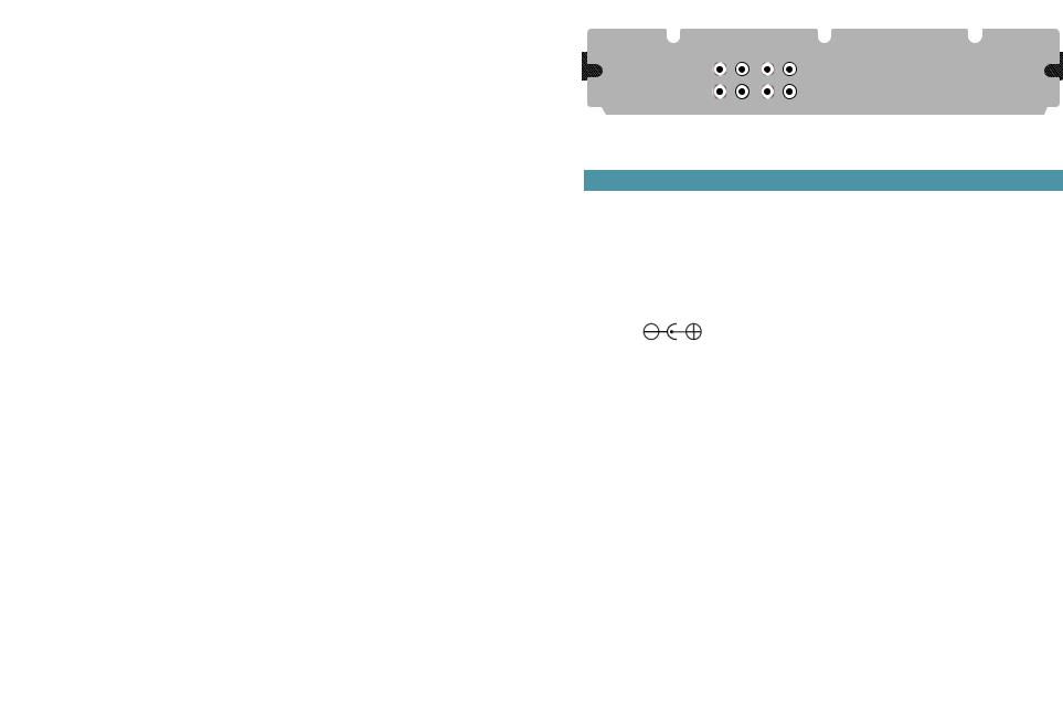
1 |
|
|
|
|
|
AUDIO |
|
|
|
|
|
For connection to amplified speaker |
|
|
|
|
|
|
|
|
|
|
|
|
|
|
|
|
|
|
|
||||||||||||||||||||||||
|
|
|
|
|
OUTPUT |
|
|
|
|
|
|
|
|
|
|
|
|
|
|
|
|
|
|
|
|
|
|||||||||||||||||||||||||||||
|
|
|
|
|
|
|
|
|
|
|
|
|
|
|
|
|
|
|
|
|
|
|
|
|
|
|
|
|
|
|
|
|
|
|
|
|
|
|
|
|
|
|
|
|
|
|
|
|
|||||||
|
|
|
|
|
|
|
|
|
|
|
|||||||||||||||||||||||||||||||||||||||||||||
2 |
|
|
|
|
|
VIDEO IN |
|
|
Video input for connecting analog video signal input (BNC) |
|
|||||||||||||||||||||||||||||||||||||||||||||
|
|
|
|
|
|
|
|
|
|
|
|
|
|
|
|
|
|
||||||||||||||||||||||||||||||||||||||
3 |
|
|
|
|
|
AUDIO IN |
|
|
Audio input for connecting audio signal (4 feeds) |
|
|
|
|
|
|
|
|
||||||||||||||||||||||||||||||||||||||
|
|
|
|
|
|
|
|
|
|
|
|
|
|
|
|
|
|
|
|
|
|
|
|
|
|
|
|
|
|
|
|
|
|
|
|
|
|
|
|
|
|
|
|||||||||||||
4 |
|
|
|
|
|
|
|
|
|
|
|
|
|
|
DC 19V Power Connection |
|
|
|
|
|
|
|
|
|
|
|
|
|
|
|
|
|
|
|
|
|
|
|
|
|
|
|
|||||||||||||
|
|
|
|
|
|
|
|
|
|
|
|
|
|
|
|
|
|
||||||||||||||||||||||||||||||||||||||
5 |
|
|
|
|
|
VIDEO OUT |
|
|
Video output for connecting TV (BNC) |
|
|
|
|
|
|
|
|
||||||||||||||||||||||||||||||||||||||
|
|
|
|
|
|
|
|
|
|
|
|
|
|
|
|
|
|
|
|
|
|
|
|
|
|
|
|
|
|
|
|
|
|
|
|
|
|||||||||||||||||||
6 |
|
|
|
|
|
NETWORK |
|
|
For connecting Ethernet cable |
|
|
|
|
|
|
|
|
|
|
|
|
|
|
|
|
|
|
|
|
|
|
|
|
|
|
|
|||||||||||||||||||
|
|
|
|
|
|
|
|
|
|
|
|
|
|
|
|
|
|
|
|
|
|
|
|
|
|
|
|
|
|
|
|
|
|
|
|||||||||||||||||||||
7 |
|
|
|
|
|
VGA OUTPUT |
To connect to VGA monitor |
|
|
|
|
|
|
|
|
|
|
|
|
|
|
|
|
|
|
|
|
|
|
|
|
|
|
|
|||||||||||||||||||||
|
|
|
|
|
|
|
|
|
|
|
|
|
|
|
|
|
|
|
|
|
|
|
|
|
|
|
|
|
|
|
|
|
|
|
|
|
|
||||||||||||||||||
|
|
|
|
|
|
ALARM INPUT |
8 I/O Alarm input |
|
|
|
|
|
|
|
|
|
|
|
|
|
|
|
|
|
|
|
|
|
|
|
|
|
|
|
|
|
|
||||||||||||||||||
|
|
|
|
|
|
|
|
|
|
|
|
|
|
|
|
|
|
|
|
|
|
|
|
|
|
|
|
|
|
|
|
|
|
|
|
|
|
|
|
|
|
|
|
|
|
|
|
|
|
||||||
|
|
|
|
|
|
ALARM |
|
|
I/O Output for alarm |
|
|
|
|
|
|
|
|
|
|
|
|
|
|
|
|
|
|
|
|
|
|
|
|
|
|
|
|||||||||||||||||||
|
|
|
|
|
|
OUTPUT |
|
|
|
|
|
|
|
|
|
|
|
|
|
|
|
|
|
|
|
|
|
|
|
|
|
|
|
|
|
||||||||||||||||||||
8 |
|
|
|
|
|
|
|
|
|
|
|
|
|
|
|
|
|
|
|
|
|
|
|
|
|
|
|
|
|
|
|
|
|
|
|
|
|
|
|
|
|
|
|
|
|
|
|
|
|||||||
|
|
|
|
|
|
|
|
|
|
|
|
|
|
|
|
|
|
|
|
|
|
|
|
|
|
|
|
|
|
|
|
|
|
|
|
|
|
|
|
|
|
|
|
|
|
|
|
|
|
|
|
|
|
|
|
|
|
|
|
|
RS485 |
|
|
|
|
|
RS485 for connecting PTZ |
|
|
|
|
|
|
|
|
|
|
|
|
|
|
|
|
|
|
|
|
|
|
|
|
|
|
|
|||||||||||||||||
|
|
|
|
|
|
|
|
|
|
|
|
|
|
|
|
|
|
|
|
|
|
|
|
|
|
|
|
|
|
|
|
|
|
|
|
|
|
||||||||||||||||||
|
|
|
|
|
|
|
|
|
|
|
|
|
|
|
|
|
|||||||||||||||||||||||||||||||||||||||
|
|
|
|
|
|
+12V |
|
|
|
|
|
Power supply for DC relay, the current is 100MA (to prevent |
|
||||||||||||||||||||||||||||||||||||||||||
|
|
|
|
|
|
|
|
|
|
|
short circuits) |
|
|
|
|
|
|
|
|
|
|
|
|
|
|
|
|
|
|
|
|
|
|
|
|
|
|
|
|
|
|
||||||||||||||
|
|
|
|
|
|
|
|
|
|
|
|
|
|
|
|
|
|
|
|
|
|
|
|
|
|
|
|
|
|
|
|
|
|
|
|
|
|
|
|
|
|
|
|
|
|||||||||||
|
|
|
|
|
|
|
|
|
|
|
|
|
|
|
|
|
|
|
|
|
|
|
|
|
|
|
|
|
|
|
|
|
|
|
|
|
|
|
|
|
|
|
|||||||||||||
9 |
|
|
|
|
|
USB |
|
|
|
|
|
Mouse port |
|
|
|
|
|
|
|
|
|
|
|
|
|
|
|
|
|
|
|
|
|
|
|
|
|
|
|
|
|
|
|||||||||||||
|
|
|
|
|
|
|
|
|
|
|
|
|
|
|
|
|
|
|
|
|
|
|
|
|
|
|
|
|
|
|
|
|
|
|
|
|
|
|
|
|
|
|
|
|
|
|
|
|
|
|
|
|
|
|
|
16 |
17 |

QS464
FRONT PANEL
|
|
|
|
|
|
|
|
|
|
|
|
|
|
|
|
|
|
|
|
|
|
||||||
1 |
|
2 |
|
3 |
4 |
5 |
6 |
7 |
8 |
|
|||||||||||||||||
|
|
|
|
|
|
|
|
|
|
|
|
|
|
|
|
|
|
|
|
|
|
|
|
|
|
|
|
|
|
1 |
2 |
3 |
4 |
5 |
|
|
|
|
|
|
|
|
|
|
|
|
|
|
|
|
|
|
|
||
|
|
|
|
|
|
|
|
|
|
|
|
|
USB 2.0 |
||||||||||||||
|
|
|
|
|
|
|
|
|
MENU |
|
|
|
|
|
|
|
|
OK |
|
|
|
|
|
|
|
||
|
|
|
|
|
|
|
|
|
EXIT |
|
|
|
|
|
|
|
|
|
|
|
|
|
|
|
|||
|
|
|
|
|
|
|
|
|
|
|
|
|
|
|
|
|
|
|
|
|
|
|
|
|
|||
|
6 |
7 |
8 |
9 |
0 |
|
|
|
|
|
|
|
|
|
|
|
|
|
|
|
|
|
|
|
|||
|
|
|
|
|
|
|
|
|
REC ALARM |
|
|
|
|
|
|
|
|
||||||||||
|
|
|
|
|
|
|
|
|
|
|
|
|
|
|
|
|
|
|
|
|
|
|
|||||
|
|
|
|
|
|
|
|
|
|
|
|
|
|
|
|
|
|
|
|
|
|
||||||
|
|
QS464 |
|
|
|
|
|
|
|
|
|
|
|
|
|
|
|
|
|
|
|
|
|
|
USB MOUSE |
||
|
|
|
|
|
|
|
|
|
|
|
|
|
|
|
|
|
|
|
|
|
|
|
|
|
|
|
|
Item # |
Name/ Symbol |
Description |
|
|
|
1 |
STANDBY |
Press to set the system in standby mode. Press again to wake. |
|
|
|
2 |
|
Press buttons 1-4 to view that channel full-screen |
|
|
Press buttons 1-0 to input passwords and user IDs. |
DURING PLAYBACK PRESS:
◄◄Increase reverse playback speed 1X, 2X, 4X.
|
CHANNEL/ |
|
Press to freeze playback to one frame, then press |
|
NUMBERS/ |
n/► again to advance frame-by-frame. |
|
|
PLAYBACK |
|
|
|
► Press to start playback |
||
|
|
►►| |
Press to slow playback speed by 1/2, 1/4, 1/8. |
|
|
►► |
Press to increase forward playback speed 1X, 2X, |
|
|
4X. |
|
3 |
MENU/EXIT |
Press to open/close the main menu. |
|
|
|
|
|
4 |
IR SENSOR |
IR Receiver for remote control. |
|
|
|
|
|
5 |
LED |
Shows recording status and motion detection (Alarm). |
|
|
INDICATORS |
|
|
|
|
|
|
6 |
|
▲ |
Press to move cursor up; in PTZ mode, press to pan |
|
|
camera up. |
|
|
|
▼ |
Press to move cursor down; in PTZ mode, press to |
|
NAVIGATION |
pan camera down. |
|
|
◄ |
Press to move cursor left; in PTZ mode, press to pan |
|
|
|
||
|
|
camera left. |
|
|
|
► |
Press to move cursor right; in PTZ mode, press to |
|
|
pan camera right. |
|
7 |
|
In menus, press to confirm selections; in PTZ mode, press to |
|
|
OK |
change the navigation buttons to control a connected PTZ |
|
|
|
camera (not included) |
|
|
|
|
|
8 |
|
USB |
The upper port is to connect a USB flash drive for |
|
|
|
data backup and firmware upgrades. |
|
|
|
The lower port is to connect a USB mouse. |
|
|
|
|
REAR PANEL
|
|
|
|
|
|
|
|
|
|
|
|
|
|
|
|
|
|
|
|
|
|
|
|
||
1 |
|
2 |
3 |
|
4 |
|
5 |
|
|
|
|
||||||||||||||
|
|
ON/OFF |
|
|
|
|
|
|
|
|
|
|
|
|
|
|
|
|
|
|
|
|
|
|
|
|
|
|
|
AUDIO |
OUT |
VIDEO IN |
|
|
AUDIO |
IN |
|
|
|
|
|
|
|
||||||||
|
|
|
|
|
|
|
|
|
|
1 |
|
|
3 |
|
|
1 |
|
|
|
|
RJ45 |
|
|
|
|
|
|
|
|
|
|
|
|
|
|
|
|
|
|
|
|
|
|
485A |
485B |
|
VGA |
||||
|
|
|
|
|
|
|
|
|
|
|
|
|
|
|
|
|
|
|
|
|
|||||
- |
|
+ |
|
|
|
|
|
|
2 |
|
|
4 |
|
2 |
|
|
|
|
|
|
|
|
|
||
|
|
|
|
|
|
|
|
|
|
|
|
|
|
|
|
|
|
|
|
|
|
||||
|
|
|
|
|
|
|
|
|
|
|
|
|
|
|
|
|
|
|
|
|
|
||||
|
DC |
+12V |
VIDEO |
OUT |
|
|
|
|
|
|
|
|
|
|
|
|
|
|
|
|
|
||||
|
|
IN |
|
|
|
|
|
|
|
|
|
|
|
|
|
|
|
|
|||||||
|
|
|
|
|
|
|
|
|
|
|
|
|
|
|
|
|
|
|
|
|
|
|
|||
|
6 |
|
|
7 |
|
|
|
|
|
|
|
|
|
|
|
|
9 |
|
10 |
|
|||||
|
|
|
|
|
|
|
|
|
|
|
|
|
|
8 |
|
|
|||||||||
|
|
|
|
|
|
|
|
|
|
||||||||||||||||
Item # |
|
|
Connector |
|
|
Description |
|
|
|
||||||||||||||||
|
|
|
|
|
|
|
|
|
|
|
|
||||||||||||||
1 |
|
|
|
|
|
Power Switch |
|
Power On/Off |
|
|
|
||||||||||||||
|
|
|
|
|
|
|
|
|
|
|
|
|
|
|
|
|
|
|
|
|
|
|
|||
2 |
|
|
|
|
|
AUDIO |
|
|
|
|
|
For connection to amplified speaker |
|||||||||||||
|
|
|
|
|
OUTPUT |
|
|
||||||||||||||||||
|
|
|
|
|
|
|
|
|
|
|
|
|
|
|
|
|
|
|
|||||||
|
|
|
|
|
|
|
|
|
|
||||||||||||||||
3 |
|
|
|
|
|
VIDEO IN |
|
|
Video input for connecting analog video signal input (BNC) |
||||||||||||||||
|
|
|
|
|
|
|
|
|
|
||||||||||||||||
4 |
|
|
|
|
|
AUDIO IN |
|
|
Audio input for connecting audio signal (2 feeds) |
||||||||||||||||
|
|
|
|
|
|
|
|
|
|
||||||||||||||||
5 |
|
|
|
|
|
NETWORK |
|
|
For connecting Ethernet cable |
||||||||||||||||
|
|
|
|
|
|
|
|
|
|
|
|
|
|
|
|
||||||||||
6 |
|
|
|
|
|
|
|
|
|
|
|
|
|
|
DC 12V Power Connection |
||||||||||
|
|
|
|
|
|
|
|
|
|
||||||||||||||||
7 |
|
|
|
|
|
VIDEO OUT |
|
|
Video output for connecting TV (BNC) |
||||||||||||||||
|
|
|
|
|
|
|
|
|
|
|
|
|
|||||||||||||
8 |
|
|
|
|
|
RS485 |
|
|
|
|
|
RS485 for connecting PTZ |
|||||||||||||
|
|
|
|
|
|
|
|
|
|
|
|
|
|
|
|
||||||||||
9 |
|
|
|
|
|
USB |
|
|
|
|
|
Mouse port |
|
|
|
||||||||||
|
|
|
|
|
|
|
|
||||||||||||||||||
10 |
|
|
|
|
VGA OUTPUT |
|
To connect to VGA monitor |
||||||||||||||||||
|
|
|
|
|
|
|
|
|
|
|
|
|
|
|
|
|
|
|
|
|
|
|
|
|
|
18 |
19 |
Loading...