


Q-See QC804, QC828, QC808, QC824, QC818 Remote Monitoring Guide
...
Remote Monitoring
Setup Guide
QC SERIES NVR MODELS
Apple Macintosh
Computer
iPhone
Setup Guide for Remote Internet and Smartphone Monitoring,
MyQ-See DDNS, and Email Notification
Android
BlackBerry*
* Select Models
PC with Windows
Operating System
1
Thank You for Choosing a Q-See Product!
This manual was accurate at the time it was completed. However, because of our ongoing
THANK YOU FOR PURCHASING THIS Q-SEE PRODUCT.
effort to constantly improve our products, along with smartphone and router manufacturers
EVERY EFFORT HAS BEEN MADE TO MAKE THIS NVR SIMPLE TO ASSEMBLE AND USE. HOWEVER, IF
adding and changing features on their products, it is possible that some functions may
YOU SHOULD RUN INTO ANY DIFFICULTIES DURING ITS INSTALLATION OR OPERATION, WE ARE HERE
FOR YOU.
change from how they are described. We encourage you to visit our website at www.Q-see.
com to check for the latest firmware and sofware updates as well as product announcements.
Throughout the manual we have highlighted warnings and other important information that will
assist you in operating your new system in a safe and trouble-free manner. Please take the
time to read and follow all instructions and pay attention to alerts as shown below:
IMPORTANT! Red boxes with this icon indicate warnings. To prevent
possible injury or damage to the product, read all warnings before use.
NOTE! Text in blue boxes with the Information icon offer additional guidance
and explanations about how to make the most out of your system.
TABLE OF CONTENTS
1. REMOTE ACCESS 5
1.1 Connecting your NVR to a Network 6
Before You Get Started 6
Obtaining an IP Address 6
1.2 Opening Ports 8
Option 1: UPnP 8
Option 2: Opening Ports Using DMZ 9
Option 3: Opening Ports Using DMZ on 2Wire Routers 10
Confirming That Ports are Opened 11
1.3 Static Internal IP (Network) Address 12
1.4 PPPOE 13
1.5 Domain Name System (DNS) 14
1.6 Dynamic Domain Name Service (DDNS) 16
1.7 Resolving Connection Issues 17
Determine the Number of Routers on the Network 17
Setting Up DMZ in Router 2 19
Every effort has been made to make this manual easy to understand and follow. However, if
you should run into any difficulties during any of these operations, we are here for you.
QUESTIONS OR COMMENTS? CONTACT US
24/7 TECHNICAL RESOURCES,
KNOWLEDGE BASE AND MORE
www.Q-See.com/Support
© 2011-12 Q-See. Reproduction in whole or in part without written permission is prohibited.
All rights reserved. This manual and software and hardware described herein, in whole or in
part, may not be reproduced, translated, or reduced to any machine-readable form without
prior written approval.
Trademarks: All brand names and products are trademarks or registered trademarks of their
respective owners.
Q-See is a registered trademark of DPS, Inc.
Disclaimer: The information in this document is subject to change without notice. The
manufacturer makes no representations or warranties, either express or implied, of any kind
with respect to completeness of its contents.
Manufacturer shall not be liable for any damages whatsoever from misuse of this product.
2. ADDITIONAL SETTINGS 20
2.1 Advanced Network Settings 20
Online Users 20
IP Filter 21
NTP 22
E-Mail 23
FTP 24
2.2 Additional Settings 25
Record Setting 25
Account 26
3. REMOTE MONITORING 27
3.1 Accessing your NVR remotely from a Computer 27
Accessing the NVR Using Internet Explorer 27
Accessing the NVR Using PSS on a PC 32
Accessing the NVR On a Macintosh 33
3.2 Remote Monitoring with Internet Explorer 34
3.3 Using Pro Surveillance Software (PSS) 45
(Continued Next Page)
Version 1.1 10/26/12
2 3
4. REMOTE DEVICES 58
4.1 Connecting to IP Cameras Over the Internet 58
Connecting to a Local Network 58
Opened Ports and Internet IP address 60
Connecting to the Remote IP Camera 61
4.2 Using the Web Service App 63
Live View 63
Setup 64
Network 66
Event 68
Record 70
System 72
Alarm 74
Logout 74
4.3 Troubleshooting Connection Issues 75
Issues with DHCP 75
Obtaining IP Information Using IPCONFIG 76
5. MOBILE SURVEILLANCE 78
5.1 iPhone and iPad 78
5.2 Android 85
5.3 BlackBerry 89
5.4 Symbian 92
5.5 Windows Mobile 95
REMOTE ACCESS
In order to access your NVR remotely, you must connect it to a router or a modem. Using
a router allows you to connect to your NVR from other computers on your LAN (Local Area
Network) in addition to over the Web. Directly connecting to a modem makes your NVR
available for connection through the Internet only.
If you are using a router and wish to access your NVR from outside your LAN either over the
Internet, or from your mobile device, then that router must be connected to the Internet. The
instructions below will guide you through the process of configuring your NVR for remote
access. Once completed, you will be able to access and control your system using one of
two addresses. You will have a local IP address usable by computers connected to the same
router as your NVR. This address can also be used by wireless devices as long as they are
able to also connect to your router’s WiFi signal. Once you leave the area covered by your
local network, you will need to use a second address to access the NVR. This is the address
which will allow you to connect to your system from anywhere in the world with Internet
access. And, by using Q-See’s free DDNS service, MyQ-See.com (more on this later), you’ll be
able to do so using a conventional web address.
If you are using a router, proceed with Section 1.1. If you are connecting directly to the
Internet via a modem then begin with Section 1.4.
NOTE! The minimum speed on the internet connection is 1Mbps download
and 1Mbps upload for 4 and 8 channels, and 2Mbps download and upload
for 16 channels. You can check the speed of your connection at both ends by
going www.SpeedTest.net from both a computer attached to the same router as the NVR
as well as the remote computer which you will be using.
Startup Wizard and the Remote Monitoring Quick Start Poster
If you were able to connect your computer to your network, and to the Internet, using the
Startup Wizard when you powered up your NVR, you should skip to Section 1.3 Static
Internal IP Address in order to ensure that your network address does not change in the
event of a power outage.
Likewise, if you were able to successfully connect using the Startup Wizard, then the NVR
was able to connect using UPnP, or Universal Plug ‘n Play and your ports have already been
opened. In this case, it is very important to NOT attempt to open your ports as that will cause
communication errors between your NVR and the network, possibly preventing reliable remote
access.
If you were unable to connect to your network, the most likely cause is UPnP being disabled,
or not available on your router. Two alternate connection options are presented for PC users
on the Remote Monitoring Quick Start Poster. They are also presented again in Section 1.2
Opening Ports, along with instructions for Maciintosh users.
CHAPTER 1
4 5
1.1 CONNECTING YOUR NVR TO A NETWORK
View 1
View 4
View 8
View 9
View 16
Pan/Tilt/Zoom
Color Setting
First and foremost, you will need to physically connect your NVR to a router. This router can
be part of an existing network of computers, or it can be the router/modem supplied by your
Internet Service Provider (ISP) to connect you to the Internet. This connection will be made by
plugging the included Ethernet cable into the port on the back of the NVR marked RJ45. Your
NVR is not designed to be connected wirelessly to a network. It is also recommended that the
router that the NVR is connected to should be connected directly to the Internet rather than
to another router if Internet access is desired as multiple routers can create problems with
connectivity. You will also need to have a computer connected to the same router - at least
temporarily - to make certain settings. If, after following the instructions you are still not able
to access your NVR, please see Section 1.7 Resolving Connection Issues later in this
chapter.
BEFORE YOU GET STARTED
You will need to have:
• Your router’s brand, model number and manual. The manual is also usually available on
your router’s manufacturer’s website.
• The “Manuals and Software” CD that came with your NVR. It contains necessary software
and links to other important programs which are mentioned in this guide.
• Your router’s password (the default password should be in your router’s manual).
OBTAINING AN IP ADDRESS
Each device on a network - both a LAN or the Internet - has a specific IP address. This
address is what allows different devices on the network to communicate with each other. Your
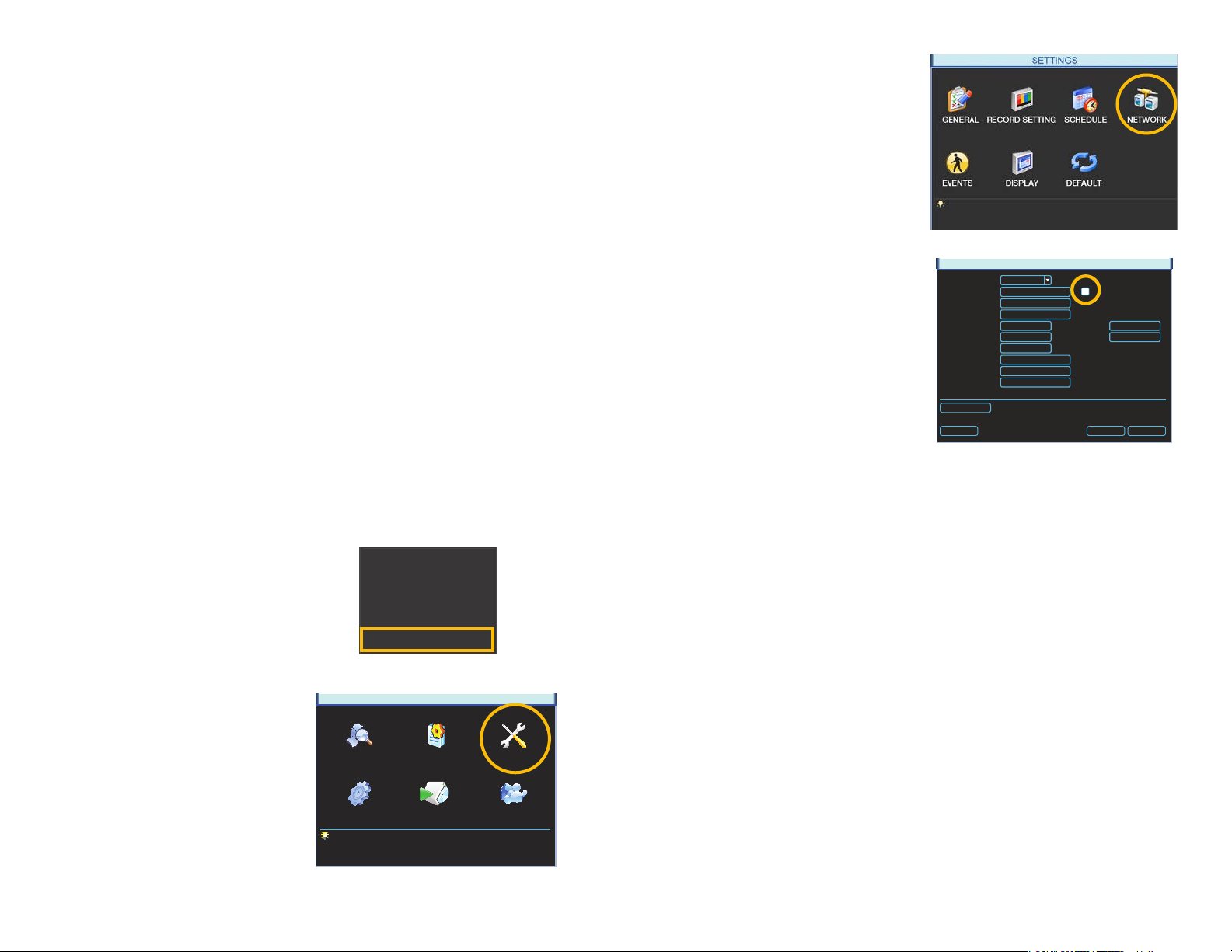
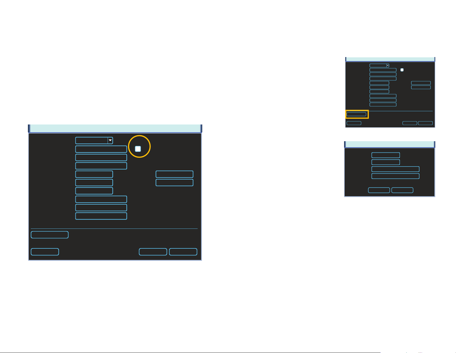
QC-series NVR displays its IP address in the Network window.
STEP 3. Click on the Network icon in
the Settings Menu.
STEP 4. Ensure that the box labeled
“DHCP” is lled.
If it is not, please click on the box so
that it is filled in white. Click on Save
and then exit the window. Reopen
the window to see the updated IP
address.
STEP 5. Write down the:
1. NVR’s IP Address
2. Subnet Mask, and
3. Gateway (your Router’s address)
STEP 6. Exit Menu
IP Version
P Address
Subnet Mask
Gateway
TCP Port
UDP Port
Max Connection
Preferred DNS
Alternate DNS
WAN IP
Network Setting
Default
PICTURE 1-3
IPv4
0 . 0 . 0 . 0
1
255 . 255 . 255 . 0
2
0 . 0 . 0 . 0
3
37777
37778
20
0 . 0 . 0 . 0
0 . 0 . 0 . 0
0 . 0 . 0 . 0
PICTURE 1-4
NETWORK
HTTP Port
RTSP Port
DHCP
80
554
Save Cancel
You may now proceed to Section 1.2 Advanced Settings. However, if you are unable to
obtain an IP address from your router, please proceed to Section 1.3 Static IP.
STEP 1. Select Main Menu from the
Shortcut Menu.
Search
Record
Remote Device
Alarm Output
Main Menu
PICTURE 1-1
STEP 2. Click on the Settings icon in
the Main Menu
SEARCH INFO SETTING
MAIN MENU
ADVANCED BACKUP SHUTDOWN
PICTURE 1-2
6 7
1.2 OPENING PORTS
To make your NVR accessible from outside of your local network, you have to “forward” ports
85 and 37777 through your router to your NVR’s IP address. The most preferred - and easiest
- method is UPnP. This is the method used by the Startup Wizard and for most users, the
NVR should connect automatically. If not, we offer some other methods which should work
for the majority of users. You will only need to use one of these methods - which are the same
if you are using a Macintosh or Windows PC. If you are unable to connect your NVR to the
Internet using any of these procedures, the likely cause is the presence of multiple routers on
your network. The solution is covered in Section 1.7 Resolving Connection Issues.
OPTION 1: UPNP
The QC series of NVRs come configured to take advantage of the latest networking
technology, UPnP or Universal Plug ‘n Play right out of the box. If you have an UPnP-enabled
router with that function turned on, you will only need to plug the NVR into your network and
you will then be able to proceed to the end of this section.
Consult your router’s manual to determine
whether it has UPnP or not. Please note that,
as of this writing, 2Wire brand routers do not
have the UPnP feature. If you do not have a
UPnP-enabled Router, you will have to utilize
another method to forward your ports.
If you wish to ensure that UPnP is turned on
in your NVR, go to the Network window as
described above, and check that the UPNP
option is checked in the Advanced Settings
area in the lower part of the window. If it is
not checked, click on the box to add the
check, then click on Save before exiting the
window. When you reopen the window, the
box should be checked.
IP Version
P Address
Subnet Mask
Gateway
TCP Port
UDP Port
Max Connection
Preferred DNS
Alternate DNS
WAN IP
Network Setting
Default
NETWORK
IPv4
0 . 0 . 0 . 0
255 . 255 . 255 . 0
0 . 0 . 0 . 0
37777
37778
20
0 . 0 . 0 . 0
0 . 0 . 0 . 0
0 . 0 . 0 . 0
PICTURE 1-5
HTTP Port
RTSP Port
DHCP
80
554
Save Cancel
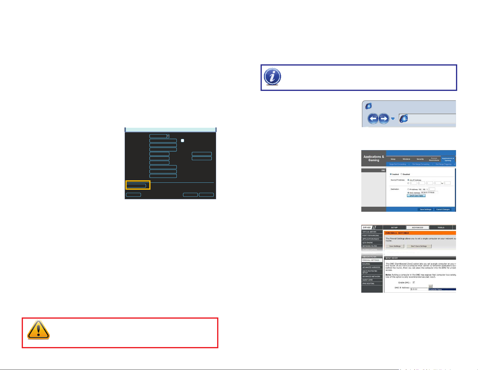
OPTION 2: OPENING PORTS USING DMZ
Accessing your router’s DMZ controls:
The exact location of DMZ within the router’s settings vary by manufacturer so please consult
your router’s manual for the location of this feature. The method for accessing your router’s
settings, however, is pretty standard.
NOTE! If you are an AT&T Internet or Uverse customer, you should follow the
instructions laid out in Option 3 as they specifically apply to the brand of router
used by AT&T.
STEP 1. On a computer connected to
the same router as the NVR, open a
web browser and enter the Gateway
(Router’s IP address) into the browser
window’s address bar to access your
router.
STEP 2. Locate the DMZ settings in
your router. Each manufacturer is
different so please consult your
router’s manual for the location of this
setting. Two examples are shown at
right.
STEP 3. Enable DMZ.
STEP 4. Enter the NVR’s IP address.
Browser - Windows Internet Explorer
hp://10.6.196.6
PICTURE 1-6
PICTURE 1-7
STEP 5. Click on Apply or Save to
preserve your settings.
Leave your router control panel open as you
will need to obtain DNS information from
your router in Section 1.5 Domain Name
System (DNS). You should now proceed to
the section entitled Confirming that Ports
are Opened.
PICTURE 1-8
IMPORTANT! If you connect your system to your network using UPnP you
should NOT forward your ports as described later in this section as it will
create connectivity problems. You may skip to Confirming that Ports are
Opened.
8 9
OPTION 3: OPENING PORTS USING DMZ ON 2WIRE ROUTERS
r
Page Safety Tools
This page will serve as a free utility for remotely verifying a port is open or closed. It will
be useful for users who wish to check to see if a server or ISP is blocking certain ports.
Accessing your router’s DMZ controls:
2Wire brand routers are currently the exclusive router used for AT&T’s Uverse and other
Internet servers. Their configuration protocols are different enough that you should follow
these instructions rather than the generic router instructions in Option 2 if you are an AT&T
customer.
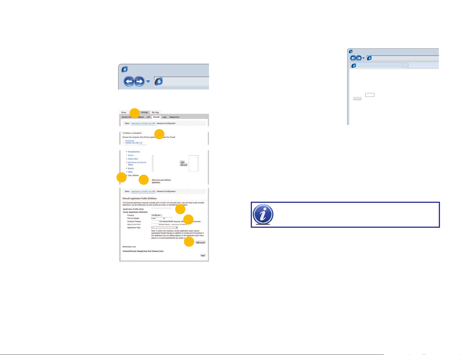
STEP 1. On a computer connected to
the same router as the NVR, open a
web browser and enter the Gateway
(Router’s IP address) into the browser
window’s address bar to access your
router.
STEP 2. Click on the Settings tab and
then Firewall. Once in Firewall,
click on Applications, Pinholes and
DMZ.
STEP 3. In the Select Your Computer
area, locate your NVR’s IP address
and click on it.
STEP 4. Scroll down to select User
Defined.
STEP 5. Click on Add a new user-
defined application.
STEP 6. In the box labeled Application
Profile Name, enter “NVR”.
STEP 7. Ensure that TCP is selected.
STEP 8. Enter 85 in the From and To
boxes for Port (or Range).
STEP 9. Leave the next two boxes blank
to use the default settings.
STEP 10. Click on Add to List. Your
router will require you to log in to
accept the settings. If you have not
created your own password for your
router, it is the 10-digit System Key
printed on the label on your router
between the square brackets “[ ]”.
STEP 11. Once your settings have been confirmed, repeat Steps 8-10, this time
entering 37777 for the From and To ports.
STEP 12. Click on Back and then select NVR from the list of Applications. Clicking on
Add and then Save.
Leave your router control panel open as you will need to obtain DNS information from your
router in Section 1.5 Domain Name System (DNS).
Browser - Windows Internet Explore
PICTURE 1-9
2
3
4
5
PICTURE 1-10
hp://10.6.196.6
6
7-8
10
CONFIRMING THAT PORTS ARE OPENED
To confirm that your ports have been forwarded successfully, go to www.canyouseeme.org
using a computer connected to the same router as the NVR.
STEP 1. Enter “85” into the box labeled
“What Port?”
STEP 2. Click on the Check button.
STEP 3. You should see a green
“Success” message. If not, return to
the NVR’s Network window and, in
the Network tab, change port 85 to
81 or 83 and click Apply to save your
changes before checking using that
new number on CanYouSeeMe.
STEP 4. Repeat for port 37777. If there
is a problem with port 37777, then try
37000 in the same manner as above.
This website will also display your Public IP address near the top of the page above the box
where you entered your port number. This is the number which you will use to access the NVR
using a web browser or your mobile device from outside of your local network (away from the
building in which your NVR is located).
NOTE! If you are successful after changing from port 85, then you will need
to add that to the IP address when accessing the NVR via the Internet. If, for
example, you changed to port 81, the address would now read 64.245.112.90:81
Browser - Windows Internet Explorer
hp://canyouseeme.org/
Open Port Check Tool
CanYouSeeMe.org - Open Port Check Tool
Your IP: 81.919.622.24
What Port?
Check
Success: I can see your service on
81.919.622.24 on port (85)
Your ISP is not blocking port 85
PICTURE 1-11
10 11
1.3 STATIC INTERNAL IP (NETWORK) ADDRESS
Most routers assign connected devices a random IP address that is not currently in use by
another device on your internal network. With the exception of 2Wire brand routers, when
a router or networked device reboots due to a power loss or other issue, the addresses will
change and the port forwarding configuration will no longer work. For that reason, unless
you have a 2Wire router, we recommend changing your NVR’s network setting to a fixed,
or “static” IP address which will not change.
STEP 1. Return to the Network Menu.
STEP 2. Uncheck the box marked DHCP.
STEP 3. Click Save.
Proceed to Section 1.5 Domain Name System (DNS) without closing the window.
NETWORK
IP Version
P Address
Subnet Mask
Gateway
TCP Port
UDP Port
Max Connection
Preferred DNS
Alternate DNS
WAN IP
Network Setting
Default
IPv4
0 . 0 . 0 . 0
255 . 255 . 255 . 0
0 . 0 . 0 . 0
37777
37778
20
0 . 0 . 0 . 0
0 . 0 . 0 . 0
0 . 0 . 0 . 0
HTTP Port
RTSP Port
DHCP
80
554
Save Cancel
1.4 PPPOE
If you are going to attach the NVR directly to a DSL or cable modem instead of to a router
then select the PPPOE option in the Network options. Before you proceed, you will need to
contact your ISP to obtain your User Name and Password. You will not have to worry about
Static IP (previous section).
NETWORK
STEP 1. Click the Network Settings
button.
STEP 2. Double-click on PPPOE to
open the window.
STEP 3. Input the User Name and
Password provided by your ISP into
their respective fields.
STEP 4. Click OK to save your settings.
Click on Save in the Netwok window
before closing that window.
STEP 5. Restart your NVR and return to
the PPPOE window. Your NVR will
have automatically connected to the
Internet and you can use the number
in the IP address field to remotely
access the NVR.
IP Version
P Address
Subnet Mask
Gateway
TCP Port
UDP Port
Max Connection
Preferred DNS
Alternate DNS
WAN IP
Network Setting
Default
User Name
Password
IP Address
IPv4
0 . 0 . 0 . 0
255 . 255 . 255 . 0
0 . 0 . 0 . 0
37777
37778
20
0 . 0 . 0 . 0
0 . 0 . 0 . 0
0 . 0 . 0 . 0
HTTP Port
RTSP Port
PICTURE 1-13
PPOE
0 . 0 . 0 . 0
0 . 0 . 0 . 0
OK Cancel
PICTURE 1-14
DHCP
80
554
Save Cancel
PICTURE 1-12
12 13
1.5 DOMAIN NAME SYSTEM (DNS)
Page Safety Tools
ADVANCED
All of your Internet and network connecon details are displayed on this page.
MACINTOSH AND PC USERS
Once you have completed the above sections, you are able to operate your NVR remotely.
The sections below allow you to take advantage of additional features including the ability to
access your NVR using a conventional domain name and having your system send out e-mail
alerts. To access these functions, you will have to access your router to obtain your DNS
(Domain Name System) number.
STEP 1. Return to your router’s control
window.
If you did not have to open your
router in a previous step, simply open
a new browser window and enter
the Gateway address (covered in
Section 1.1)
STEP 2. Locate your router’s status
window (may also be named
“Information” or “Info”, it will list the
DNS number. You will only need to
use the primary set of numbers write it down for later use.
STEP 3. In the NVR’s Network window,
enter the DNS number in the area
marked Preferred DNS. You do not
need to have an alternate server.
STEP 4. Click Save to save your
settings.
Browser - Windows Internet Explorer
hp://81.919.622.24
Router
DEVICE INFO
LOGS
STATISTICS
INTERNET SESSIONS
ROUTING
WIRELESS
SETTINGS
DEVICE INFORMATION
WAN
MAC Address :
Subnet Mask :
Default Gateway :
Primary DNS Server :
Secondary DNS Server :
Advanced DNS :
IP Address :
STATUS
00:24:01:77:f9:00
81.919.622.249
255.255.255.0
81.919.622.24
10.6.196.6
(null)
Disabled
PICTURE 1-15
NETWORK
IP Address
Subnet Mask
Gateway
TCP Port
UDP Port
Preferred DNS
Alternate DNS
ADVANCED SETTING
DDNS No Available DDNS Setup
UPNP Port Forwarding
EMAIL MailServer: 25
FTP Record FTP : 0.0.0.0
Default Save Cancel
0 . 0 . 0 . 0
0 . 0 . 0 . 0
0 . 0 . 0 . 0
37777
37778
0 . 0 . 0 . 0
0 . 0 . 0 . 0
Transfer Mode
LAN Download
HTTP Port
Max Connection
Latency
DHCP
80
20
PICTURE 1-16
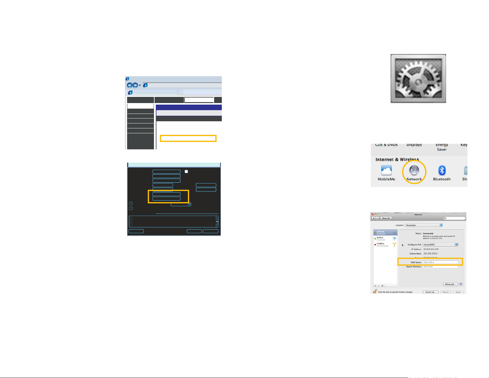
MACINTOSH COMPUTERS
In addition to retrieving the DNS info from the router, Macintosh users can get it from the
computer’s Network window.
STEP 1. Click on the System
Preferences icon at the bottom of
the Macintosh’s screen.
PICTURE 1-17
STEP 2. Click on the Network icon.
PICTURE 1-18
STEP 3. Make sure that your network
connection is highlighted in the list of
connections to the right of the main
part of the Network window and
that its status reads “Connected.”
The DNS server information will be
shown. Write this down for use in the
next section.
PICTURE 1-19
14 15
1.6 DYNAMIC DOMAIN NAME SERVICE (DDNS)
This is an optional step which allows you to take advantage of Dynamic Domain Name
Service, or DDNS. Not to be confused with DNS above, DDNS allows you to enter a
conventional web address when remotely logging into your NVR from outside of your network.
It also allows you to avoid having to repeat Sections 1.3 and 1.5 when/if your ISP reassigns
IP addresses. Q-See offers DDNS service for free at www.MyQ-See.com and your NVR is
configured to accept account information from that site.
STEP 1. Open a browser window and go
to www.MyQ-See.com
STEP 2. Register with the website and
follow the instructions for creating
a domain name. The website will
display your pubic IP address and
your domain name which will look like
this: http://example.myq-See.com
STEP 3. In your NVR, open the Network
window.
STEP 4. In the Advance Settings area at
the bottom of the window, scroll until
you find DDNS and double-click on it
to open the DDNS window.
STEP 5. Check the Enable box and
select MyQ-See.com in the DDNS
server pull-down menu.
STEP 6. Enter your account information
– including the user name and
password that you used when
creating your domain name .
STEP 7. Click the Save button to
preserve your settings.
STEP 8. When you return to the
Network window, ensure that the
DDNS box is checkmarked before
clicking on Save as well before
closing.
NEW USER REGISTRATION
EMAIL ADDRESS
PASSWORD
PASSWORD
CONFIRM
FIRST NAME
LAST NAME
SECURITY
QUESTION..
ANSWER
CONFRIM
YOU’RE HUMAN
My first phone number
New Captcha
Enter the text you see above
Submit
Reset
Submit
Reset
PICTURE 1-20
NETWORK
IP Address
Subnet Mask
Gateway
TCP Port
UDP Port
Preferred DNS
Alternate DNS
ADVANCED SETTING
DDNS No Available DDNS Setup
UPNP Port Forwarding
EMAIL MailServer: 25
FTP Record FTP : 0.0.0.0
Default Save Cancel
0 . 0 . 0 . 0
0 . 0 . 0 . 0
0 . 0 . 0 . 0
37777
37778
0 . 0 . 0 . 0
0 . 0 . 0 . 0
Transfer Mode
LAN Download
HTTP Port
Max Connection
Latency
DHCP
4
80
20
PICTURE 1-21
DDNS
DDNS Type
Server IP
Port
Domain Name
User Name
Password
Update Period
Q-SEE DDNS
myq-see.com
85
300
6
5
Enable
sec.
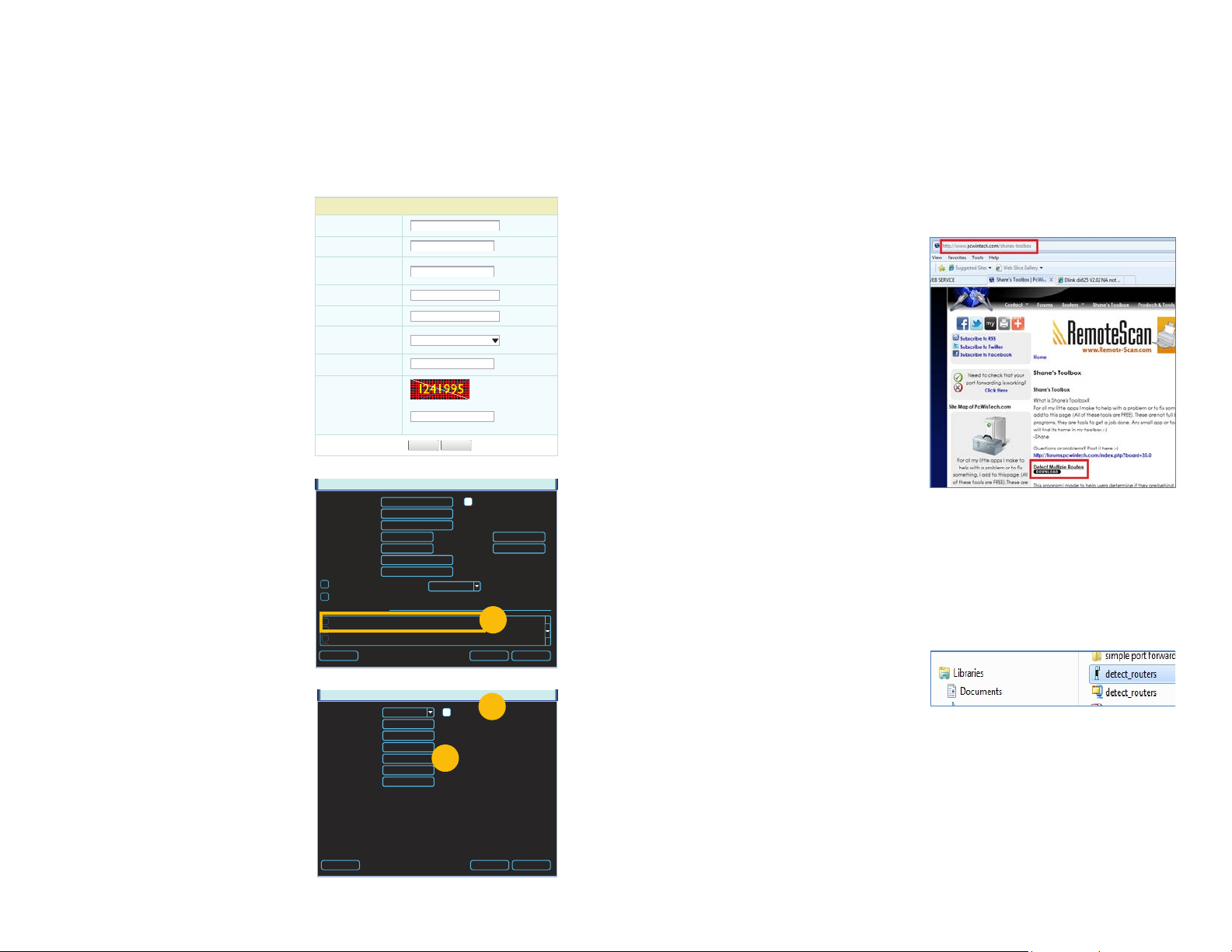
1.7 RESOLVING CONNECTION ISSUES
There are several hardware-related situations which can prevent the NVR’s port from being
properly forwarded. The presence of multiple routers or the routers not featuring UPnP or
DMZ are the two most common issues.
DETERMINE THE NUMBER OF ROUTERS ON THE NETWORK
If there is more than one router between the NVR and the Internet it will block communication
to and from your system. To find out the number of routers on your network, you will need to
download a FREE router detection program.
STEP 1. Go to http://www.pcwintech.
com/shanes-toolbox
STEP 2. Click on Detect Multiple
Routers to begin the download.
STEP 3. Unzip the application to install it.
STEP 4. Click on the detect_routers
application to run it.
PICTURE 1-23
PICTURE 1-24
Default Save Cancel
PICTURE 1-22
16 17
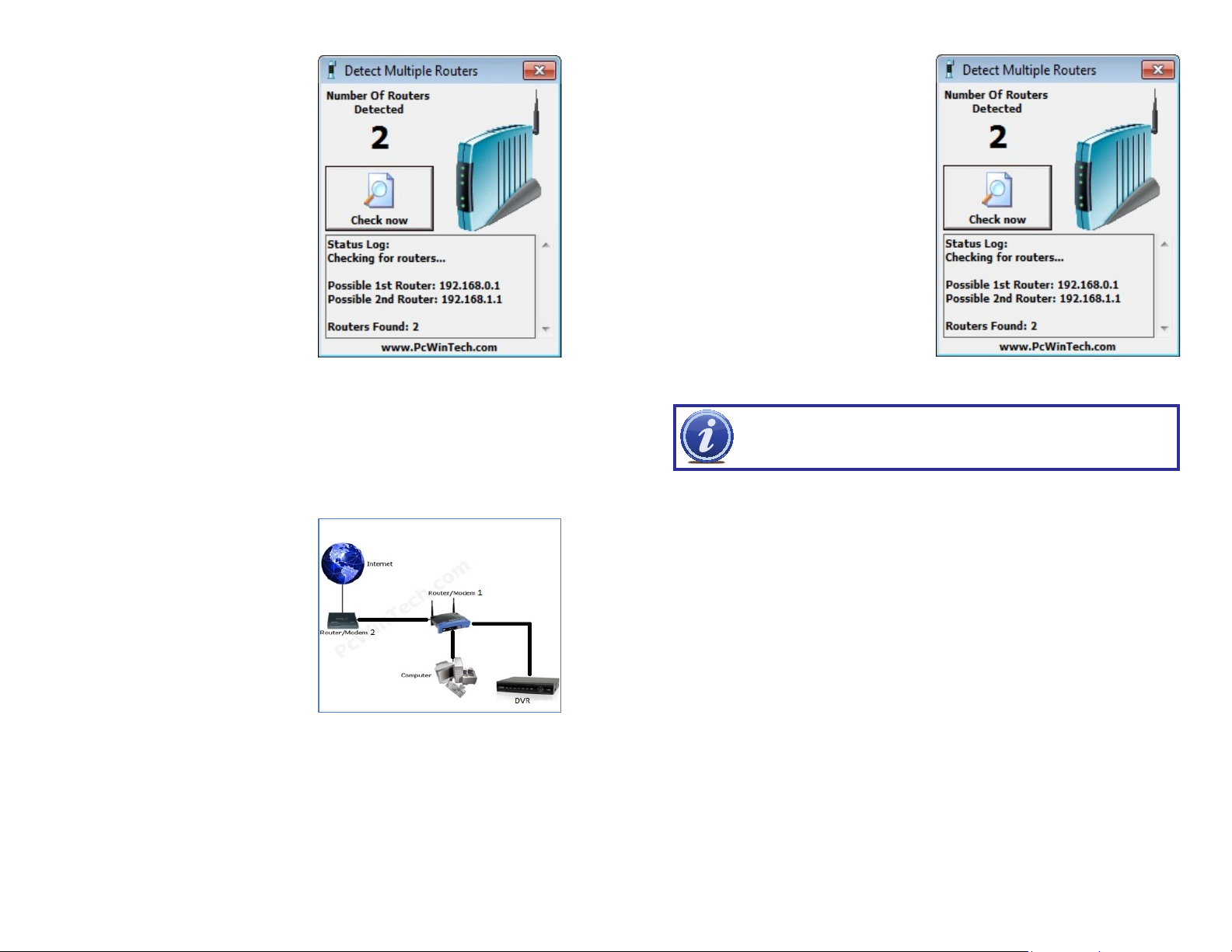
STEP 5. Click on CHECK NOW to
detect how many Routers are in the
network.
PICTURE 1-25
STEP 6. If there is only one router detected, and you are using UPnP, then you will need
to turn off that setting and attempt to connect using DMZ as described in Section
1.2 Opening Ports.
If you are using DMZ, check to make sure that the UPnP option is turned off.
If Multiple Routers are Detected
If there are multiple routers, you will see a
display similar to Picture 1-26.
If so, it may be preferable to connect your
NVR and computer to the router that
connects directly to the Internet. However,
this is not always possible depending upon
your particular situation.
SETTING UP DMZ IN ROUTER 2
STEP 1. Login into Router 1 by putting
the IP of Router 1 into the Internet
Explorer browser, as in the example
shown in Picture 1-25 where the IP
address of Router 1 is 192.168.0.1
STEP 2. Find the status page on the
router settings that shows the WAN/
Internet IP address and write it down
this WAN IP address.
STEP 3. Log into the Router 2 by putting
the IP of Router 2 into the Internet
Explorer browser, as in example
shown in Picture 1-26 where the IP
address of Router 2 is 192.168.1.1
STEP 4. Find the DMZ page in the
router settings.
STEP 5. Enter the WAN IP for Router 1
into the DMZ page and enable DMZ.
NOTE! If you do not have a DMZ setting in the router, check to see if there
is a Bridge setting. If so, then use the Bridge setting instead of DMZ.
STEP 6. Save your changes.
You have forwarded the ports on the router to which the NVR is connected, to the IP address
of the NVR, and set the second router to pass the connection to this router.
PICTURE 1-26
PICTURE 1-26
In this case, you will need to proceed with the next section and set up DMZ in the second
router to allow communications to pass through it from the first. If only one router is detected
you will need to consult your router’s manual.
18 19
ADDITIONAL SETTINGS
CHAPTER 2
2.1 ADVANCED NETWORK SETTINGS
Now that you’ve successfully connnected your NVR to your network and to the Internet, there
are additional features which you can take advantage of. These settings allow your NVR to
send out e-mail alerts as well as post images and records to an FTP site. In addition, you can
see which users are online, limit online access and more.
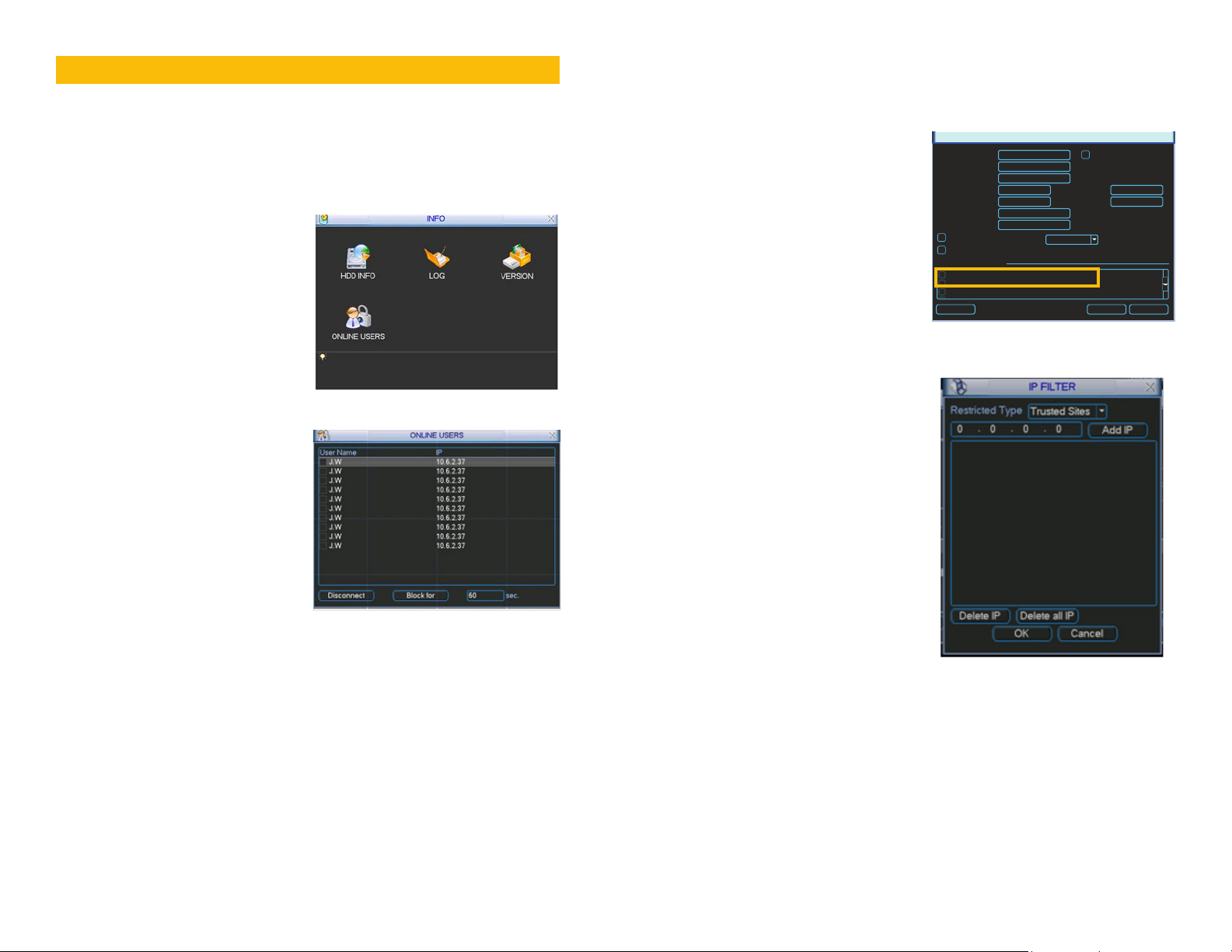
ONLINE USERS
A list of users accessing the NVR from over
the network or through the Internet is shown
in Online Users menu which itself is found in
the Info menu.
PICTURE 2-1
The user’s name as well as the IP address
used to access the NVR is displayed.
If you have proper system management rights
(Configured in Account, See Section 4.4
Advanced in the User’s Manual for full
instructions), you can disconnect or block
a user. The maximum time a user can be
disconnected is 18 hours (65,535 seconds).
PICTURE 2-2
IP FILTER
You can also improve security by controlling remote access to your NVR using the IP Filter.
This feature enables you to allow online users only from approved IP addresses. Up to 64
addresses may be entered.
The IP Filter window is accessed through
the Advanced Settings area of the
Network menu.
Enter the trusted IP addresses into the field at
the top of the window and select Add IP to
add that address to the list of those allowed
to connect to the NVR.
Once this feature is enabled, only IP
addresses within this list can be used to
access the NVR. If this feature is not enabled,
then users can connect from any IP address
if they have the correct user name and
password information.
IP Address
Subnet Mask
Gateway
TCP Port
UDP Port
Preferred DNS
Alternate DNS
ADVANCED SETTING
IP Filter Trusted Sites : 0
NTP windows.time.com : 24
PPOE
DDNS No Available DDNS Setup
Default Save Cancel
NETWORK
0 . 0 . 0 . 0
0 . 0 . 0 . 0
0 . 0 . 0 . 0
37777
37778
0 . 0 . 0 . 0
0 . 0 . 0 . 0
Transfer Mode
LAN Download
Latency
PICTURE 2-3
DHCP
HTTP Port
Max Connection
80
20
PICTURE 2-4
20 21
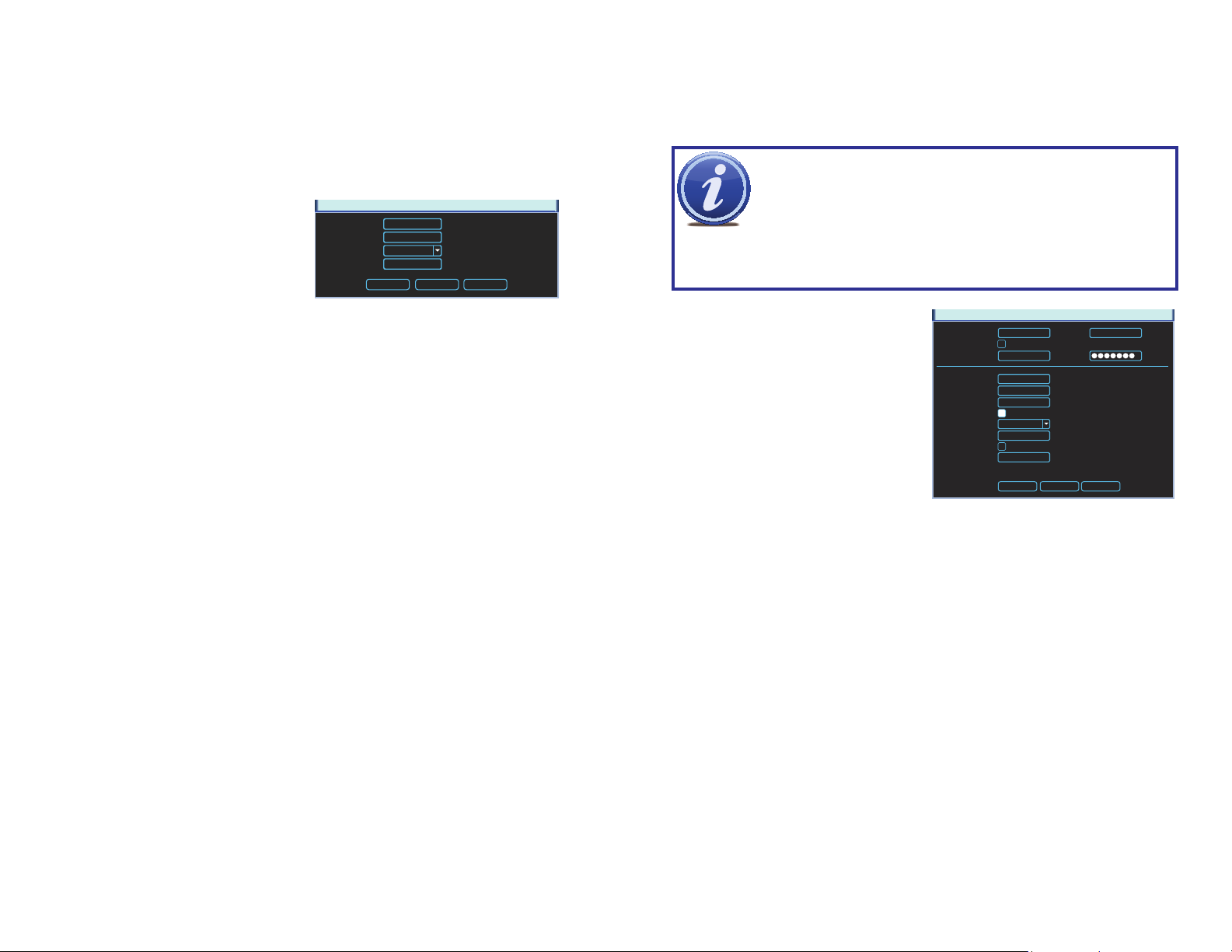
NTP
Network Time Protocol (NTP) is used to synchronize the time of a computer or other device
connected to the Internet. Utilizing this feature allows your NVR to keep an accurate time as
well as automatically adjust to Daylight Savings Time changes.
NTP was set up as part of the Startup Wizard process, but you can always return via the
Advanced Settings area of the Network menu to make adjustments.
Server IP - The default server used to
obtain accurate time is the Windows
server, but you can manually enter in
another.
Port - This is the port that the NVR
will use to contact the server.
Server IP
Port
Time Zone
Update Period
OK Cancel Synchronize
Time Zone - You will need to set your
time zone. For North America these
are:
Eastern Time Zone = GMT-5 Central Time Zone = GMT-6
Mountain Time Zone = GMT-7 Pacific Time Zone = GMT-8
Alaskan Time Zone = GMT-9 Hawaii Time Zone = GMT-10
Update Period - This is the frequency at which the NVR will check the time with the
server.
Synchronize - Clicking this will cause the NVR to update the time immediately.
NTP
time.windows.com
123
GMT-8:00
24
PICTURE 2-5
Hours
Several NVR functions allow you to send out e-mail alerts when specific events occur.
Configuring this feature lets you set the NVR up to send out alerts via e-mail to a single
recipient. You may need to contact your e-mail provider or IT department for some required
information.
NOTE! Depending upon your settings, the system can generate a lot of e-mail
alerts. For that reason, we recommend setting up a dedicated e-mail address
specifically for the system to send alert notices. If you do not have your own
e-mail system (such as a corporate mail server) you should consider using a
limited amount of e-mail traffic we specifically recommend using Google’s Gmail service with
its higher limit. Similarly, you will want the alert e-mails to go to a different account than the
one sending them. This will ease your management of these alerts.
SMTP Server – This the SMTP server IP
Port – This is the port your mail provider uses
User Name and Password – These are for
Title – This is the subject line of e-mails
Receiver – This is the recipient e-mail
Attachment – This allows the e-mail to
SSL Enable – The system supports SSL
Interval – This adjusts the amount of time
free e-mail provider. However, because many free e-mail services allow only a
EMAIL
name
the sending e-mail address and were
set up when you created the e-mail
account.
generated by this NVR.
account.
SMTP Server
Anonymous
User Name
Receiver
Sender
Title
Attachment
Encrypt Type
Event Interval
Health Enable
Interval
smtp.gmail.com 465
DVR ALERT
NONE
3
60
Port
Password
Min.
Min.
PICTURE 2-6
include one or more snapshots as
attachments
encryption when this is enabled.
that will pass before the NVR sends
out another e-mail. The interval can
be set from 0 seconds to ten hours
(3600 seconds). If you are getting
too many e-mails, you may wish to
increase the length of the interval.
Using this feature also helps prevent
overloading your outgoing e-mail
server.
TestOK Cancel
22 23
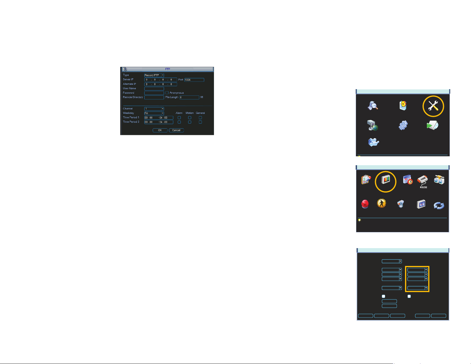
FTP
File Transfer Protocol (FTP) allows you to securely share, manage, and distribute files over the
internet. You will need to already have a server and FTP service tool to utilize this feature on
the NVR.
Follow the software’s instructions to set up your service, password and FTP folder. You will
need to grant Write privileges to the FTP upload user.
Enter the FTP server address, port and
remote directory. If the remote directory is left
blank, the system will automatically create
folders according to the IP, time and channel.
User Name and Password – This is the
account information created when
you set up your FTP and is used to
allow the NVR to log into the server.
File Length – This is the maximum length (in
minutes). Files under the maximum
will upload completely. Files longer
than the maximum limit will only
upload to that limit and not continue.
If the value is left at 0, there is no limit
and the system will upload all files
completely.
The lower portion of this window allows you to set up to two upload periods for each channel.
Recordings made during the time(s) selected will be uploaded to the server. You can specify
which type of incidents will be uploaded as well.
PICTURE 2-7
2.2 ADDITIONAL SETTINGS
You may need to adjust your settings in the Record Setting and Account windows to ensure
trouble-free remote monitoring. Complete instructions on their use can be found in Chapter
5 of the User Manual.
RECORD SETTING
Whether monitoring your NVR via a computer or your smartphone, you may need to adjust
the Extra Stream settings to match the capabilities of your network or wireless provider.
MAIN MENU
The Record Setting window is located in the
Setting menu.
If you are experiencing any performance
issues in your remote or mobile viewing,
adjust the settings in the Extra Stream
portion of the Record Setting window. Most
QC-series NVRs will only allow the use of the
smaller QCIF (Quarter CIF) resolution format
for this second stream. The CBR bit rate
type is generally better for remote streaming.
Adjust the frame rate to find the best
performance for your particular situation.
SEARCH INFO SETTING
ADVANCED BACKUPREMOTE DEVICE
SHUTDOWN
PICTURE 2-8
SETTING
RECORD SETTINGGENERAL SCHEDULE NETWORKRS232
EVENTSALARM PAN/TILT/ZOOM DISPLAY DEFAULT
PICTURE 2-9
Remember that changes made in the Extra
Stream section do not effect how your NVR
records to its own drive.
Channel
Compression
Resolution
Frame Rate (FPS)
Bit Rate Type
Bit Rate (Kb/S)
Reference Bit Rate 384-2048Kb/S
Audio/Video
Copy Paste Default Save Cancel
RECORD SETTING
Main Stream
1
H.264
D1
25
Constant
2049
OVERLAY
SNAPSHOT
Extra Stream
H.264
CIF
7
Constant
160
PICTURE 2-10
24 25
ACCOUNT
When logging in remotely, you will have the same privileges and authorities as you do when
accessing the NVR directly. This includes which cameras can be monitored and played back,
PTZ controls and other aspects.
The Account window can be found in the
Advanced menu.
SEARCH INFO SETTING
ADVANCED BACKUP SHUTDOWN
MAIN MENU
PICTURE 2-11
REMOTE MONITORING
CHAPTER 3
3.1 ACCESSING YOUR NVR REMOTELY FROM A COMPUTER
You can access your NVR remotely using a computer on the same network as your system or
from any computer using the Internet. QC-series NVRs can be accessed on a PC using the
Windows operating system either through Internet Explorer or by using the PSS software that
is included on the Manuals and Software CD that came with your system.
ACCESSING THE NVR USING INTERNET EXPLORER
Accessing your NVR using Internet Explorer is generally as simple as using an interactive
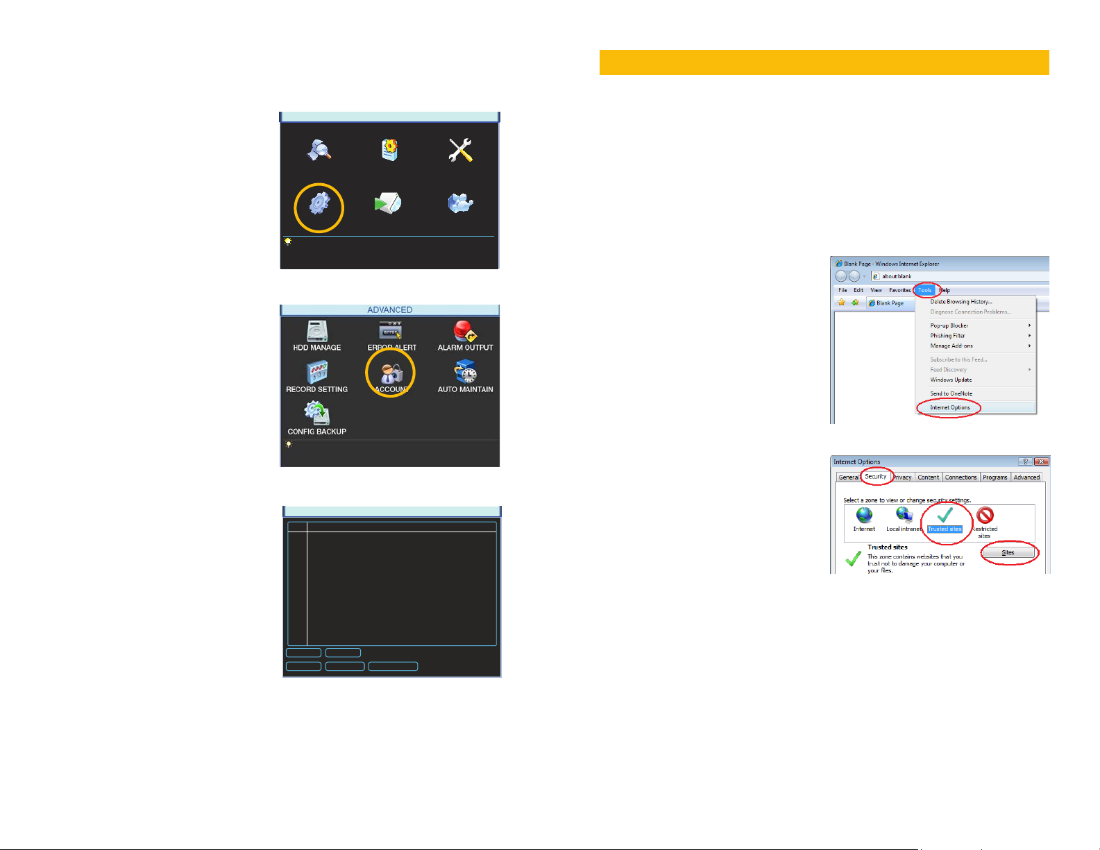
website. Some users may need to configure Microsoft’s built-in ActiveX controls prior to
logging into their NVR in order to ensure smooth operation.
Setting Up ActiveX Control
STEP 1. Open Internet Explorer
STEP 2. Click on Tools
STEP 3. Select Internet Options in the
pull-down menu
PICTURE 3-1
PICTURE 2-12
STEP 4. Click on the Security Tab
STEP 5. Select Trusted Sites
If you do not log out of your NVR - or if
you wish to allow multiple users to monitor
the NVR using the same account - then
you should select the account, then click
on Modify User. Check the box next to
“Reusable” for that account before saving
3 User Group Status
1 admin admin Normal
2 local admin admin Login Local
3 user user Default User
ACCOUNT
STEP 6. Click on the Sites button
PICTURE 3-2
and exiting the window.
Add User Modify User
Add Group Modify Group Modify Password
PICTURE 2-13
26 27
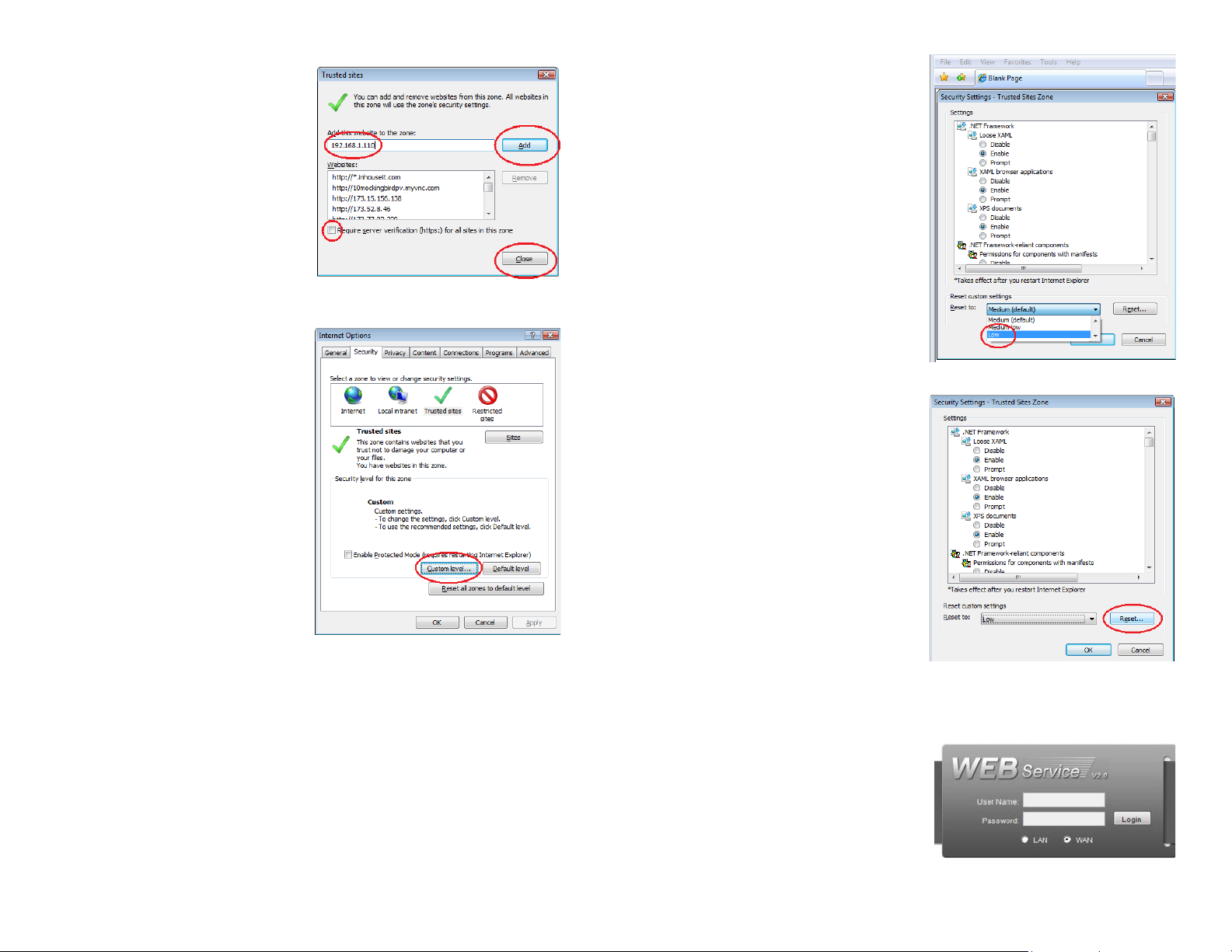
STEP 7. Uncheck the “Require server
verification (https:) for all sites in
this zone” button.
STEP 8. Type the NVR’s IP address
(obtained during Network Setup)
or DDNS domain name into the “Add
this website to the zone:” box.
STEP 9. Click the Add button
STEP 10. Close the window.
STEP 11. Click the Custom level…
button.
STEP 12. Pull down the “Reset to:”
menu button and select Low
PICTURE 3-3
PICTURE 3-5
STEP 13. Click the Reset button
STEP 14. Click “Yes” when asked, “Are
you sure you want to change the
setting for this zone?”
STEP 15. Click OK
STEP 16. Click Apply
STEP 17. Click OK
PICTURE 3-4
STEP 18. Close Internet Explorer
PICTURE 3-6
Open a browser window in Internet Explorer and enter the IP address or DDNS name
(obtained in Section 1.1) into the address bar.
You will see a log in screen similar to that
shown in Picture 3-7 or yellow alert bar at
the top of the window asking for permission
to open an ActiveX application. Allow it to
install webrec.cab control to reach the
sign-in screen.
Proceed to Section 3.2 Monitoring with
Internet Explorer for instructions on
logging in and remote monitoring.
PICTURE 3-7
28 29
 Loading...