


Q-See QCN8025Z Quick Start Guide
IP PTZ Camera
POE PORTS
POE PORTS
POE PORTS
Quick Installation Guide
DPQCN8025Z 11-26-14 EN
IMPORTANT!
You should read and understand this guide before
proceeding in order to ensure proper operation of
your camera.
Gather Your Components.
You will need:
1. A power screw driver/drill to mount your cameras. A Philips head and 3/16” drill bit are required.
2. A bubble or spirit level to ensure proper orientation of the mounting bracket.
3. A pencil or small marker to mark the mounting holes.
Connecting the Camera
Internet Protocol (IP) or Network cameras are different from conventional video surveillance cameras by having their own internal processor which allows them to
operate as a stand-alone device or to communicate with other networked devices. This not only allows you greater flexibility in how you connect them to your NVR,
but it also gives you more choices in where you place your cameras.
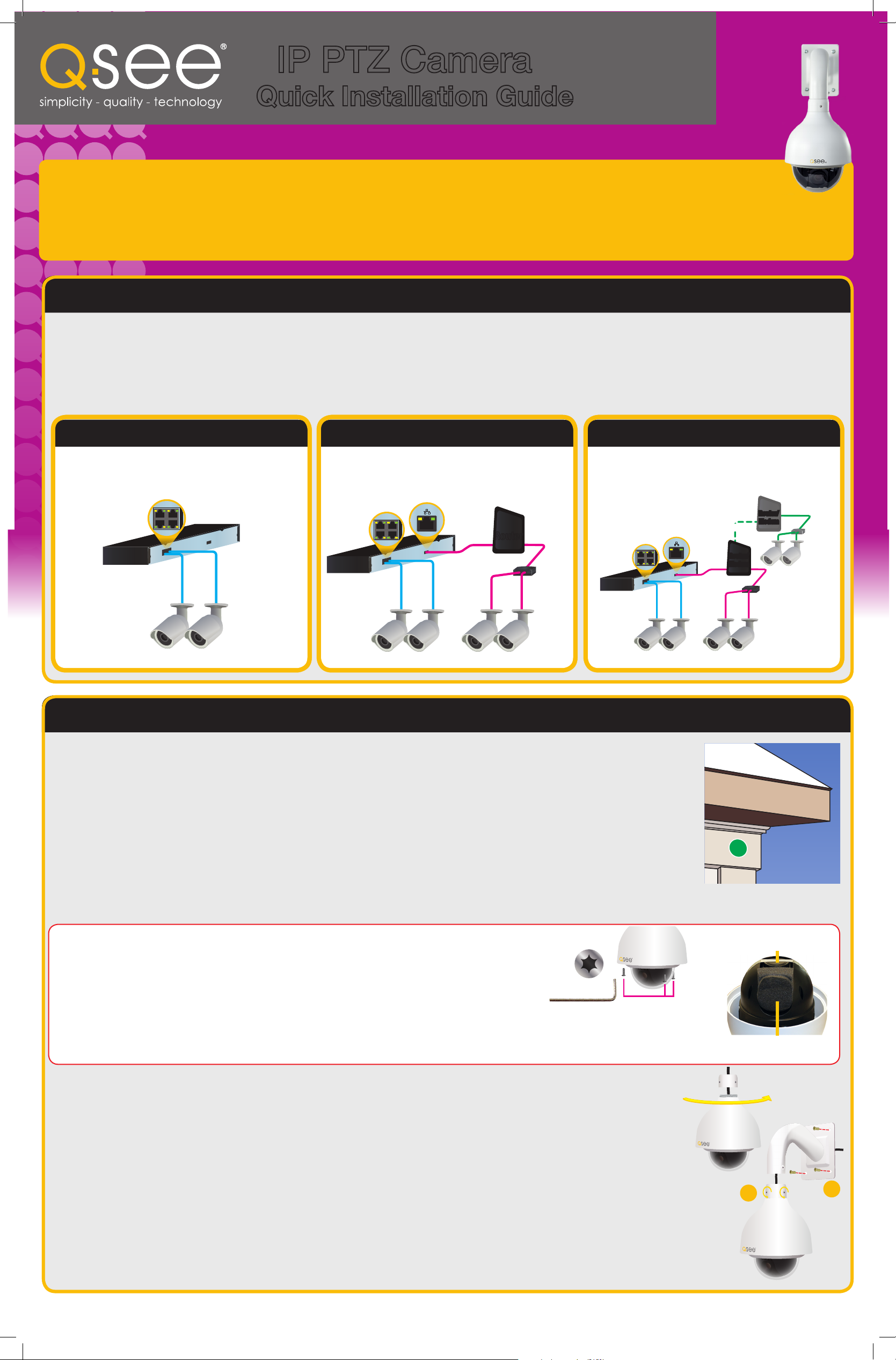
This poster covers only the direct connection method (Option 1, below) where the camera is plugged into the POE port on the
back of the NVR. If you will be using one of the other methods, or if you will be using this camera without an NVR, please consult
the manual located on the CD that was included with this camera.
OPTION 1: Direct Connection OPTION 2: Local Network Connection OPTION 3: Internet Connection
Camera is connected directly to the NVR
through a POE port on the back of the unit. No
additional cords are required.
Camera is connected to the NVR through the
same network router. You will need to use the
included 24V power supply.
Camera is connected to the NVR through the
Internet. You will need to use the included 24V
power supply.
POE
Block
POE
Block
Network
Port
RouterRouter
POE
Splitter
POE
Block
Network
Port
INTERNET
INTERNET
Router/
Router/
Modem
Modem
Mounting the Camera
When installing your camera, it is important to select a proper site not only for field of view, but for other considerations
as well. The optimal location for your camera will depend on your unique circumstances. As a general rule, the location
highlighted in green in the picture to the right indicate the best place to mount your camera as it is under the eaves and
high up, but you should also take into consideration:
• Distance from viewing/recording device.
• Proximity to high voltage wires or other sources of
electrical interference.
Expanded information on these aspects can be found in your camera’s manual.
• Camera should be out of reach to avoid damage.
• Avoid direct exposure to weather.
• Do not place camera behind a window.
Router/
Router/
Modem
Modem
POE
Splitter
POE
Splitter
Installation
Your camera is designed to be mounted on a wall using the included bracket.
BEFORE INSTALLING YOUR CAMERA: Use the included torx (star) wrench to loosen
the three housing bolts to open the lens cover. We have also included fabric gloves with
your camera to help you prevent getting fingerprints or scratches inside or outside of
the clear glass dome or camera lens. Do not remove the bolts from the cover.
Remove the foam shipping insert from the camera head along with the lens cap. These items will keep
the camera from functioning properly. Replace the lens cover. Take care to not touch or move the camera
mechanism or leave fingerprints or dust on the lens or the inside of the lens cover during this process.
1. Run the included 100’ network cable from the NVR to the camera’s location or a network port.
2. Use the mounting bracket to mark the position for the mounting holes. Ensure that the camera will be horizontal by
using a spirit or bubble level. Also mark location of hole for cables to pass through the mounting surface.
3. Drill the mounting and cable holes.
4. Insert included mounting anchors into surface.
5. Screw mounting collar onto camera body.
6. Feed the cables through the mount and out the hole in the back before securing the camera/collar assembly to the
mounting bracket.
x3
Tape and lens cap
Remove and discard.
Shipping foam
Remove and discard.
7
9
7. Tighten the three retaining screws on the collar so that the camera housing does not turn.
8 Connect the camera cables to the extension cable.
9. Secure the camera and mount assembly to the wall using the included screws.
You should now continue with the set-up of your remaining cameras and NVR before proceeding with the other side of this guide.
Using the Camera
View 1
View 4
View 8
View 9
View 16
Color Setting
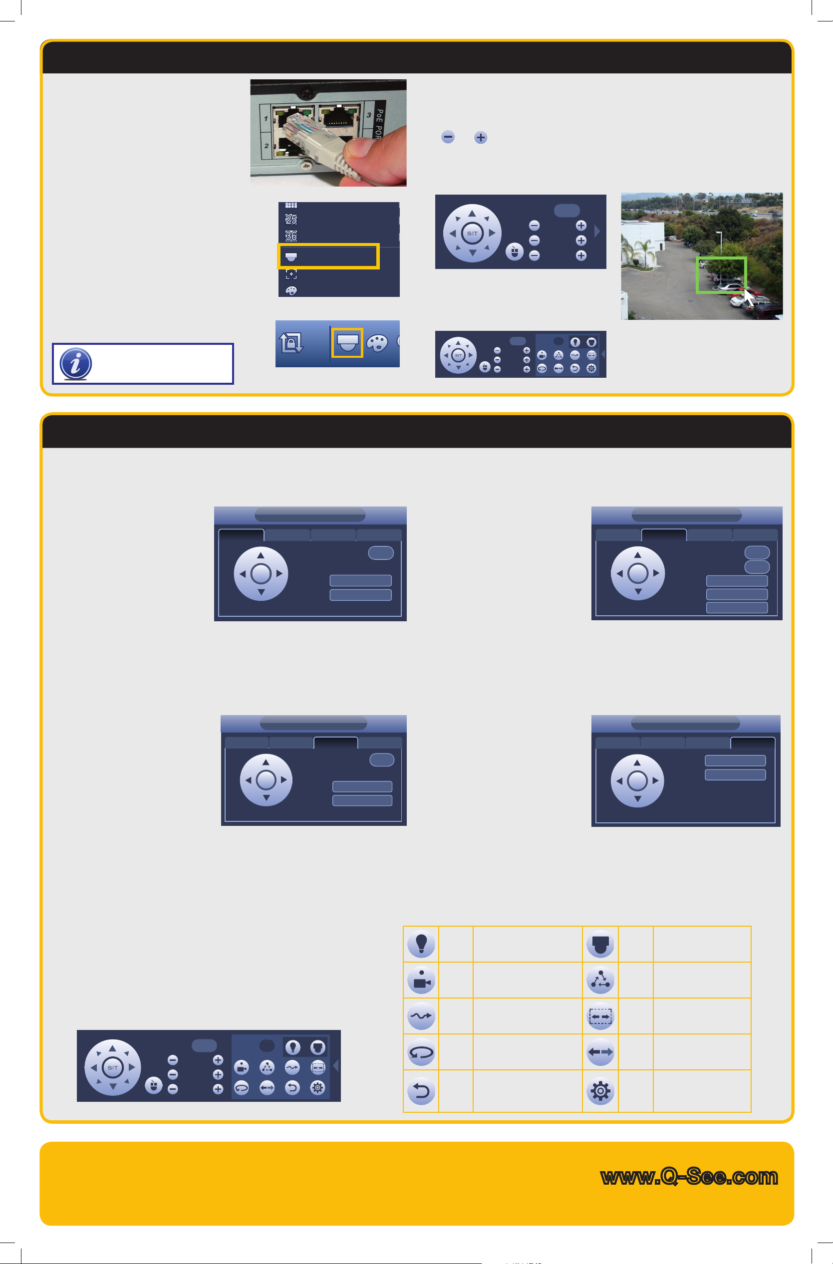
If you have not already done so, please
connect your camera to the NVR through
one of the POE ports at this time. The
camera and NVR will communicate and
the cameras video should appear in less
than a minute.
Right-click the mouse to bring up the
Shortcut Menu (right) allowing you to
select the Pan/Tilt/Zoom controls.
You can also open the controls by
clicking on the PTZ icon in the Control
Bar (below right) at the bottom of the
screen.
NOTE! IP PTZ cameras do not
require additional control wires
(RS485) to operate.
View 25
View 36
PTZ
Auto Focus
Direction is controlled by clicking and holding on a directional arrow button.
Select speed from 1 (slowest) to 8 (fastest).
Zoom, Focus and Iris (light level) can be adjusted using the
and
buttons.
Clicking on the blue area at the center of the directional controls will hide the
control panel and allow you to select an area to zoom in on with the cursor. Rightclicking with the mouse will return you to the control panel.
Speed
Speed No.
5 0
Zoom
Focus
Iris
5
Zoom
Focus
Iris
Click on the arrow at the far right to
open the expanded controls which
allows you to program and run saved
functions.
Programming the Camera
Clicking the Set button in the PTZ Control Panel opens a new window in addition to leaving the PTZ Control Panel active. This window allows you to set up the PTZ’s Preset,
Tour, Pattern and Border functions.
Preset
PTZ
1. Enter a number for this point.
(1-80)
2. Use the eight direction arrows
Preset Tour Pattern BorderPreset
Preset
0
on the PTZ Control Panel to
position the camera where you
want.
Set
Delete Preset
3. Click Set.
To create another preset point, change the Preset Number and repeat steps 2 and
3. You can program up to 80 Preset Points. When you have created the desired
preset points, you may use them to create a tour.
You can remove a preset point by clicking on the Del Preset button and an entire tour can be deleted using the Del Tour button.
Pattern
The camera will record a pattern
you create using the Directional
Controls in real-time and will
repeat it exactly when you run the
pattern.
1. Enter the number (1-5) for this
Pattern.
2. Move your camera to where you
want to start the pattern.
3. Click Start to begin the recording. The camera will record each stop, the time
spent at each point, the zoom, focus and other settings.
4. Click End when you have finished setting your pattern.
PTZ
Tour Pattern BorderPatternPreset
Pattern
0
Start
End
Tour
PTZ
A tour is the sequence of points
that your camera will move to
automatically before returning to its
starting point and repeating. You can
create up to 8 tours.
1. Enter the number (1-8) for this Tour.
2. Select the first Preset Point by
Tour Pattern BorderTourPreset
Preset
Patrol No.
Add Preset
Delete Preset
Delete Tour
0
0
entering its number.
3. Click Add Preset.
4. Enter additional points (up to 16) the same way).
Border
Use this to set the left and right
end points for the camera to shift
between during its Auto-Scan. The
camera will only rotate in a straight
line between these two points There
can be only one Auto-Scan path.
1. Move your camera to either the
left or right point.
2. Click Left or Right and then move the camera to the other point.
3. Click the other button to select the end point.
• If you get your left and right points “backwards” the camera will still move between
them, but facing the wrong way.
• When you select Auto-Scan in the PTZ Control window, the camera will move
between these two points until stopped.
PTZ
Tour Pattern BorderBorderPreset
Left
Right
Controls additional features
Aux
Running PTZ Functions
such as lamp or wipers. (If
available)
Launch a programmed function using the buttons in the far right of the
expanded PTZ controls:
Enter the number of the function you wish to activate and select the
function button to run that function.
Speed No.
5 0
Zoom
Focus
Iris
Preset
Point
Pattern
AutoPan
Stop/
Reset
Moves camera to a pre-set
point.
Camera will record your
movements and then follow
that path.
Camera will automatically
continue to rotate 360°
Stops the camera’s current
action.
Questions or Comments? Contact Us
24/7 Technical Resources at www.Q-See.com/support
Live Support Mon.-Fri. 6am to 7pm Sat & Sun 9am to 5pm Pacific time
Menu
Tour
AutoScan
Flip Flips video image.
Config
Opens the camera’s
internal on-screen menu
(if available).
Camera will move to
a sequence of pre-set
points.
The camera will move
horizontally between two
points.
Set up and save Preset
Points, Tours, Patterns
and borders for Auto
Scan
www.Q-See.com
 Loading...