


Q-See QC9416, QC904, QC9016, QC938, QC524 Technical Manual
...
QC SERIES
ANALOG HD
DVRS
1 2 3 4 5 6 7 8 9 10 11 12 13 14 15 16 NET HDD POWER
|
|
|
|
|
|
|
|
|
|
|
|
|
|
ENTER |
|
|
|
|
|
|
|
|
|
|
|
SHIFT |
REC |
FN |
ESC |
|
|
|
|
|
|
QC828 NVR 8 Channels
USER MANUAL

Thank You for Choosing a Q-See Product!
All of our products are backed by a conditional service warranty covering all hardware for 24 months from the date of purchase. Additionally, our products also come with a free exchange policy that covers all manufacturing defects for one month from the date of purchase. Permanent upgrading service is provided for the software and is available at www.Q-See.com.
Be certain to make the most of your warranty by completing the registration form online. In addition to warranty and technical support benefits, you’ll receive notifications of product updates along with free downloadable firmware updates for your DVR. Register today at www.Q-See.com!
Please see the back of this manual for exclusions.
© 2014 Q-See. Reproduction in whole or in part without written permission is prohibited. All rights reserved. This manual and software and hardware described herein, in whole or in part, may not be
reproduced, translated, or reduced to any machine-readable form without prior written approval.
Trademarks: All brand names and products are trademarks or registered trademarks of their respective owners.
Q-See is a registered trademark of DPS, Inc.
Disclaimer: The information in this document is subject to change without notice. The manufacturer makes no representations or warranties, either express or implied, of any kind with respect to completeness of its contents.
Manufacturer shall not be liable for any damages whatsoever from misuse of this product.
2
About this Manual
This manual is written for the QC900 Series of Digital Video Recorders (DVRs) and was accurate at the time it was completed. However, because of our ongoing effort to constantly improve our products, and the different capabilities of the three models additional features and functions may have been added since that time and on-screen displays may change. We encourage you to visit our website at www.Q- see.com to check for the latest firmware updates and product announcements.
This manual covers the setup and local operation of the DVR. Instructions for configuring the DVR for remote access, along with instructions for monitoring the DVR using a computer or mobile device, are contained within the Remote Monitoring Guide which is included on the CD that accompanied your DVR and which can also be found on www.Q-See.com/support.
Throughout the manual we have highlighted warnings and other important information that will assist you in operating your new system in a safe and trouble-free manner. Please take the time to read and follow all instructions and pay attention to alerts as shown below:
IMPORTANT! Red boxes with this icon indicate warnings. To prevent possible injury or damage to the product, read all warnings before use.
NOTE! Text in blue boxes with the Information icon offer additional guidance and explanations about how to make the most out of your system.
Rev. 1.2 4/28/2014
3

TABLE OF CONTENTS
1. INTRODUCTION |
6 |
|
For Your Safety |
7 |
|
Features and Capabilities |
8 |
|
2. CONNECTIONS AND CONTROLS |
10 |
|
2.1 |
Connections |
11 |
2.2 |
Mouse Control |
13 |
Virtual Keyboard |
13 |
|
2.3 |
Remote Control |
14 |
2.4 |
Live View |
15 |
Login |
15 |
|
Status Icons |
17 |
|
Navigation Bar |
17 |
|
Shortcut Video Controls |
18 |
|
2.5 On-Screen Menus and Windows |
19 |
|
2.6 |
Pan-Tilt-Zoom Cameras |
21 |
Running PTZ Functions |
22 |
|
Programming PTZ Functions |
22 |
|
3. FUNCTIONS |
24 |
|
3.1 |
Video Search |
25 |
Video Search & Playback Window |
25 |
|
Search |
26 |
|
3.2 |
Playback |
28 |
Digital Zoom |
29 |
|
Saving a File |
31 |
|
3.3 Backup |
32 |
|
3.4 Shutdown |
34 |
|
4. SETTINGS |
36 |
|
4.1 Camera |
37 |
|
Image |
37 |
|
Camera Settings |
38 |
|
Camera Name |
40 |
|
Channel Type |
40 |
|
Record Schedule |
41 |
|
Record Status |
43 |
|
PTZ |
43 |
|
4.2 |
Event |
44 |
Detections |
44 |
|
Alarm |
46 |
|
Abnormality |
47 |
|
4
4.3 Network |
48 |
TCP/IP |
48 |
Ports |
49 |
PPPOE |
49 |
DDNS |
49 |
UPnP |
50 |
Block/Allow List |
50 |
50 |
|
FTP |
51 |
4.4 Storage |
52 |
Hard Disk (HDD) Manager |
52 |
Grouping |
53 |
4.5 System |
54 |
General Settings |
54 |
Display Settings |
56 |
Account Settings |
57 |
Auto Maintenance |
58 |
Import and Export |
59 |
Default |
60 |
Upgrade |
60 |
5. INFORMATION |
61 |
|
5.1 |
System Information |
62 |
Hard Disk Drive |
62 |
|
Record |
63 |
|
Bits Per Second (BPS) |
63 |
|
Version |
63 |
|
5.2 |
Event Information |
64 |
5.3 |
Network Information |
65 |
Online Users |
65 |
|
Load |
65 |
|
Test |
66 |
|
5.4 |
Activity Log |
67 |
5.5 |
Scan N’ View |
68 |
Connecting with Mobile Devices |
68 |
|
Connecting Using a Computer |
68 |
|
Appendix |
69 |
|
A.1 |
Connecting Alarms |
70 |
Alarm Input |
70 |
|
Alarm Output |
70 |
|
A.2 |
Hard Drive Installation/Removal |
72 |
A.3 |
Troubleshooting |
74 |
A.4 |
Q-See Product Warranty |
77 |
A.5 |
Technical Support |
77 |
5

INTRODUCTION |
CHAPTER 1 |
Get to know your new system a little better. |
|
Subjects in this chapter: |
|
Important safety warnings. |
7 |
Product features. |
8 |
|
|

FOR YOUR SAFETY
To prevent damage to your Q-See product or injury to yourself or to others, read and understand the following safety precautions in their entirety before installing or using this equipment. Keep these safety instructions where all those who use the product will read them.
WARNING! ELECTRIC SHOCK RISK!
nCheck the unit and any accessories included in the package immediately after opening. If items are missing or damaged, repackage and return to the point of purchase.
nUse the proper power source. Only use the power adapter supplied with your system. Do not use this product with a power source that applies more than the specified voltage (100-240V AC).
nNever insert anything metallic into the DVR. Inserting anything into the DVR or its case can be a source of dangerous electric shock.
nDo not operate in dusty areas. Avoid placing the DVR in places that are dusty.
nDo not expose this product to rain or use near water. If this product accidentally gets wet, unplug it and contact Q-See immediately.
nKeep product surfaces clean and dry. To clean the outside case of the DVR, gently wipe using a lightly dampened cloth (only use water, do not use solvents).
nDo not operate this DVR without the cover securely in place. Do not attempt to do any repairs to the DVR yourself. If there are unusual sounds or smells coming from the DVR, unplug it immediately and contact Q-See technical support. Under no circumstances should the cover be removed while the device is connected to a power source. You should only remove the cover to install/replace the hard disk drive (Covered in Section A.2 of the Appendix) or replace the standard 3v lithium cell battery on the motherboard. These are the only user serviceable parts. You may need to replace the battery if the internal clock resets itself after a power outage
nHandle the DVR carefully. If you accidentally drop your DVR on any hard surface, it may cause a malfunction. If the DVR doesn’t work properly due to physical damage, contact an authorized dealer for repair or exchange. Damage caused by mishandling is not covered in the warranty.
nMake sure there is proper air circulation around the unit. This DVR system uses a hard drive for video storage which generates heat during operation. Do not block air holes located on the bottom, top, sides and back of the DVR as they are designed to keep the system cool while running. Install or place this product in an area where there is ample air circulation.
7

FEATURES AND CAPABILITIES
Your Analog HD DVR (Digital Video Recorder) contains brand new technology with professional-grade features and flexibility that allows the do-it-yourselfer to easily setup and maintain a reliable and secure security system for home and office.
It utilizes a dual-core CPU running an embedded Linux operating system to maintain stable operation and a popular H.264 compression algorithm to produce high-quality, low bitstream footage that is easy to manage and efficient to transfer over the internet. It can use various functions such as record,
playback, and monitoring at the same time and produces audio and video synchronization. This product has advanced network technology and data transmission functions allowing you to control and monitor your system remotely.
IMPORTANT! Even though they use identical cables and connectors, conventional analog cameras WILL NOT WORK with an AnalogHD recorder. Also, AnalogHD cameras will not work with a conventional analog recorder.
This product offers the following features:
Smartphone Compatible
Access live footage directly from your iPhone, iPad, Android phone and tablet or other supported mobile device. Your DVR can also be set to e-mail your hand held-device whenever specific activity occurs, such as motion detection.
Dual Video Streams
The DVR will record high definition video directly to its internal hard drive, while streaming a more compact, lower resolution or frame rate video feed over the network or Internet for real-time viewing on a computer or mobile device.
Single-Wire Control
The camera cable carries not only power to the camera and video from it, it also can carry two-way audio plus control signals for Pan-Tilt-Zoom cameras and those with with adjustable settings.
View Your Video Feed Online with No Additional Service Fees
View your DVR’s live or recorded video footage on any Internet accessible computer with Internet Explorer, Apple Safari, Mozilla Firefox and Google Chrome (using IE plug-in).
Stay Notified with Customizable Email Alerts
Set your system up to notify you when an event has occurred at the location you are monitoring. Notification alerts can easily be adjusted to your specifications.
Advanced Motion Detection Activated Recording
Advanced motion detection settings ensure that false alarms are minimized. The easy to use motion detect set up screen allows you to mask out certain areas which experience heavy movement in order to avoid false alarms and avoid unnecessary record triggering.
8

Multiple Backup Options
A built-in USB port gives you the option of backing up and transferring your video footage using a flash drive or external USB hard drive. Files can also be accessed from your DVR system to a remote computer location by logging on remotely.
Easily Connect to a VGA or HD Display
This system comes with VGA and HDMI video output ports to allow you to connect to a computer monitor (19” or larger) or HD display for viewing purposes.
Individually Configurable User Controls
Create up to 20 individual user accounts giving specific users access to only certain functions, cameras and etc.
24/7 Scheduled Recording
Choose which days of the week and hours of the day you want to set your DVR to record or not record.
Storage Function
Encrypted file format to ensure data security and avoid vicious data modification.
Multiple Playback Options and Advanced Search Functions
Supports real-time recording on each channel independently. Search through recorded files while you are playing live footage, monitoring through a remote location using a supported internet browsing application and backing up system files. A variety of playback modes include: slow play, fast play, backward play and frame by frame play.
Network Monitoring
Supports network remote real-time monitoring (available bandwidth permitting) and remote record search.
Alarm Activation Function
Systems with alarm ports can be paired with an on-site alarm system.
Communication Ports
Standard Ethernet port allows you to access the DVR from a network or the Internet.
NOTE! Depending on your point of purchase, your DVR may have the hard disk drive already installed. If your drive was packaged separately or if you wish to upgrade to up to a larger hard drive, please see Chapter 9 at the back of this manual which covers installing the drive.
9

CONNECTIONS AND CONTROLS |
CHAPTER 2 |
This chapter covers the ports and connectors on your DVR along with providing an introduction to the onscreen controls and menus.
Subjects in this chapter: |
|
Identifying connectors on your DVR. |
11 |
Using the mouse. |
13 |
Using the remote control. |
14 |
On-screen live viewing. |
15 |
Watching multiple cameras at the same time. |
15 |
Logging into your system. |
15 |
Using the Shortcut Menu. |
16 |
On-screen icons |
17 |
Using the Navigation Bar |
17 |
Shortcut video controls |
18 |
Menu navigation |
19 |
Pan-Tilt-Zoom cameras |
21 |
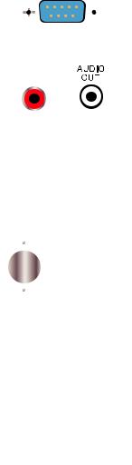
2.1 CONNECTIONS
The illustrations below show the ports found on the back of your DVR. Their location will differ by model, but their function will be the same. The Connections and Specifications sheet that came with your recorder will show the layout of your recorder’s connectors along with any extra information that may apply to your model.
DC 12V |
POWER |
VGA
Your DVR will have either a small port (top) or a larger, more conventional power port (below). DVRs with the smaller port will have a power adapter as part of the power cord while those larger power port have an internal power supply.
NETWORK PORT
Use this single Ethernet port to connect your DVR to your network router.
VIDEO IN PORTS
The yellow end of the camera extention cable connects to these ports. While they use identical cables, neither conventional analog nor SDI cameras will work with your AnalogHD system.
HDMI
Use the included HDMI cable to connect to a high-definition video display.
USB
Depending on the model of your DVR, these ports may be located on both the front and back panels. Connect your USB mouse to one of the ports on the back panel, leaving the other port available for use in backing up files.
VGA
For connecting your DVR to a VGA computer monitor. VGA cable not included.
11
Depending on your model, your DVR may have one or more of these ports as well:
RS232 |
RS232 |
|
|
|
This port is for factory maintenance only. |
AUDIO
IN
VIDEO
OUT
AUDIO
Standard RCA-type connectors. Audio In ports are for connecting microphones which have been located near a camera to capture audio. The Audio Out port is to connect to a speaker. The color of these ports may vary.
VIDEO OUT (RCA)
Connect to a standard television as a video display using an RCA cable (not included).
VIDEO OUT (BNC)
Also used for connecting a standard television as a video display. Requires a BNC-to-RCA adapter or cable.
ALARM BLOCK
 This serves as a connection point for one or more external alarms or
 sensors. Full details are given in the Alarms section of this manual.


 The size of the block will vary.
ESATA
Models with this port can back up files to an external hard drive.
12
2.2 MOUSE CONTROL
Your DVR is controlled through the USB mouse. Some models also include an infrared remote control and buttons on the front panel that serve as shortcuts.
The mouse works the same as on a computer with different functions possible:
LEFT CLICK: |
Selecting an item |
|
Opening a menu |
|
Checking a box or motion detection status |
|
Selecting letters, numbers or symbols on the virtual keyboard. |
DOUBLE CLICK: |
Selecting an event for playback |
|
Selecting a screen to zoom into from multi-screen mode |
RIGHT CLICK: |
Exits any window. Exits any menu or reopens previous menu. |
|
Opens Pop-Up Shortcut Menu (right). |
|
The options shown - especially multi- |
|
channel viewing options - will vary by |
|
model |
MOUSE WHEEL: |
Page up or page down |
|
Switch items in check box |
|
Increase or decrease numerical value in |
|
numerical input box |
CLICK-AND-DRAG: |
Select motion detection zone |
|
Select privacy mask zone |
|
PICTURE 2.2-1 |
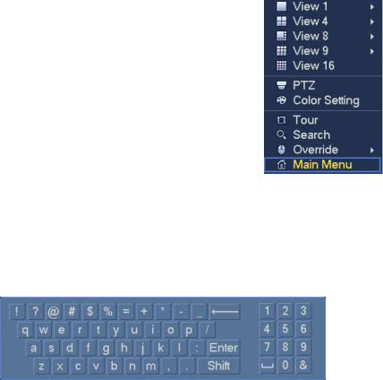
VIRTUAL KEYBOARD
Whenever a menu field requires text - such as a password, new user name, or other setting - clicking on that field will bring up the virtual keyboard. It operates as regular keyboard using the point and click function of the mouse to select individual characters. Clicking the shift key allows access to the uppercase characters.
PICTURE 2.2-2
Spaces are entered using the 
 symbol and characters are deleted with the
  key. Clicking Enter or clicking outside of the keyboard will close it.
13
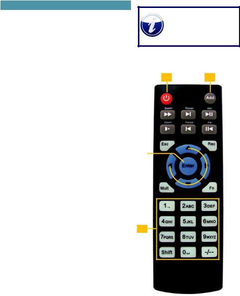
2.3 REMOTE CONTROL
The buttons on the Remote Control operate in the same manner as on a conventional video player remote. Some buttons have multiple functions depending on which menu is being accessed.
|
# |
Name |
Function |
|
|
|
|
|
1 |
Power |
Turn on or shut down the DVR before turning it |
|
|
Button |
off with the power switch. |
|
|
|
|
|
2 |
Address |
An additional security feature. You can require |
|
|
|
the DVR to ask you to enter the Device |
|
|
|
Number (found in the General Settings menu) |
|
|
|
before being able to access the log-in screen. |
|
|
|
|
|
3 |
Fast |
Multiple fast forward speeds in Playback mode. |
|
|
Forward |
Zoom in when in PTZ mode. |
|
|
|
|
|
4 |
Next |
Goes to next video in Playback mode. |
|
|
Record |
Adjust focus when in PTZ mode. |
|
|
|
|
|
5 |
Slow Play |
Multiple slow playback speeds and resumes |
|
|
|
normal playback. |
|
|
|
Zoom out when in PTZ mode. |
|
|
|
|
|
6 |
Play/Pause |
Will open Playback/Search mode. |
|
|
|
Begins playback of selected video or pauses |
|
|
|
current video. |
|
|
|
Adjust Iris (light level) in PTZ mode. |
|
|
|
|
|
7 |
Previous |
Goes to previous video in Playback mode. |
|
|
Record |
Adjust focus when in PTZ mode. |
|
|
|
|
|
8 |
Reverse/ |
“Rewind” current video or resume normal |
|
|
Pause |
playback. |
|
|
|
Adjust Iris (light level) in PTZ mode. |
|
|
|
|
|
9 |
Escape |
Cancel current function or exit current menu. |
|
|
|
|
|
10 |
Enter |
Select default button. Go to main menu. |
|
|
|
|
|
11 |
Multi-view |
Cycle through available multi-screen display |
|
|
mode |
modes. |
|
|
|
|
|
12 |
Record |
Opens recording interface. Use directional keys |
|
|
|
to select recording mode and channel. |
|
|
|
|
|
13 |
Directional |
Navigate through menus. |
|
|
Keys |
Cycle through channels in singleor 8-screen |
|
|
|
viewing mode. |
|
|
|
Control Playback progress bar in Playback |
|
|
|
mode |
|
|
|
Control PTZ camera and switch menus in PTZ |
|
|
|
mode. |
|
|
|
|
|
14 |
Function |
Opens volume control. |
|
|
|
Switches PTZ control menu |
|
|
|
Use with Directional keys to set up Motion |
|
|
|
Detection |
|
|
|
|
|
15 |
0-9 Keys |
Use in similar manner to phone keypad to enter |
|
|
|
password, etc. |
|
|
|
Push number to select desired channel for |
|
|
|
viewing. |
|
|
|
|
|
14 |
|
|
NOTE! Some DVRs are not designed to be used with a remote control and one will not be included with those models.
1 2
|
|
|
|
|
|
|
|
|
|
|
3 |
|
6 |
||||||||
|
|
|||||||||
4 |
|
|
|
|
|
|
|
7 |
||
|
|
|
|
|||||||
|
|
|
|
|
|
|
|
|
||
5 |
|
8 |
||||||||
|
|
|
|
|||||||
|
|
|||||||||
|
|
|
|
|
|
|||||
9 |
|
12 |
||||||||
|
|
|||||||||
|
|
|
|
|
|
|
|
|
|
|
10 |
|
|
|
|
|
|
|
|
|
|
|
|
|
|
|||||||
|
|
|
|
13 |
||||||
|
|
|||||||||
|
|
|
|
|
||||||
11 |
|
14 |
||||||||
|
|
|||||||||
15
PICTURE 2.3-1
2.4 LIVE VIEW
Live View is the default mode for your DVR. It will display the video feeds from your cameras - either a single channel, or from multiples. You do not need to be logged in to view or change channels.
|
|
|
|
|
|
|
|
|
|
|
|
|
|
|
|
|
|
|
|
|
|
|
|
|
|
|
|
|
|
|
|
|
|
|
|
|
|
|
|
|
|
|
|
|
|
|
|
|
|
|
|
|
|
|
|
|
|
|
|
|
Single Screen |
|
4 Screens |
|
8 Screens |
|||||||||
|
|
|
|
|
|
|
|
|
|
|
|
|
|
|
|
|
|
|
|
|
|
|
|
|
|
|
|
|
|
|
|
|
|
|
|
|
|
|
|
|
|
|
|
|
|
|
|
|
|
|
|
|
|
|
|
|
|
|
|
9 Screens |
16 Screens |
PICTURE 2.4-1
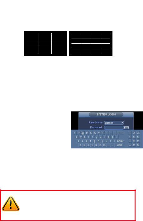
The number of channels that can be displayed at once depends on the capacity of your DVR. For instance, if you have a four-channel system, the viewing options will be limited to singleor four-screen modes.
Clicking on any one screen in multi-view mode will bring that screen to full-screen single-view mode. The exception is in eight-view where clicking on one of the smaller displays will move it to the larger display. You can also drag channels to a different position on the screen with the displaced channel relocating to the position of the one that was moved.
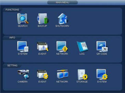
LOGIN
For your protection, the DVR will log you out after |
|
a period of inactivity. To make any changes to your |
|
system, or to view recorded video, you will need to |
|
log back in. Use the mouse to select your account |
|
from the pull-down and then to “push” the keys |
|
on the Virtual Keyboard to enter your password. |
|
Click Enter to submit the password and exit the |
|
keyboard. |
PICTURE 2.4-2 |
|
Until new accounts are added, there are two pre-configured accounts available to users who log into the DVR:
•Administrator (local and network) User name: admin Password admin
•User name user Password user
The Admin account cannot be deleted, but you can - and should - change the password.
IMPORTANT! It is highly recommended that you change your system password after you complete the setup of your system to ensure the security of your system. Record your changes and keep that information stored securely as the system will prevent access if the incorrect login information is attempted three times within a 30-minute period. If you find yourself locked out of the DVR because of this, wait 30 minutes, reboot the DVR and attempt to log into it again.
15

SHORTCUT MENU
In Live View mode, right-clicking anywhere on the screen will bring up the pop-up Shortcut Menu Shortcut Menu.
This menu allows you to quickly change your viewing mode as well as moving directly to a selection of menus, including the Main Menu.
View - This allows you to view a group of cameras on screen at the same time. The number of cameras available will depend on how many cameras your DVR will support. The arrows to the right of the view options will allow you to select specific cameras.
PTZ (Pan/Tilt/Zoom) - This will take you directly to the PTZ Control Window The controls will only work with PTZ cameras.
Color Settings - You can adjust the camera’s brightness, color balance, contrast and other aspects to best suit its operating environment. These changes can be made using the sliders or by selecting a pre-generated color mode.
Search - This opens the Search and Playback Window (See Section 3.1).
Tour - This will cause Live View to cycle through
your channels. This can be set up in Displays PICTURE 2.4-3
(See Section 4.5).
Override - This allows you to quickly change the recording status of your cameras.
Main Menu - This opens the Main Menu.
16

STATUS ICONS
There are four icons that will appear on the left side of each channel’s view. They provide a quick look at that camera’s status.
Recording |
Motion |
|
detected |
||
|
NAVIGATION BAR
When this is enabled in the General Settings menu, left-clicking on the Live View display will open the Navigation Bar allowing you shortcut access to select menus and functions. It also serves as an easy-to- view status bar showing the current situation with alerts, network, and drives.
|
|
|
|
|
|
|
|
|
|
|
|
|
|
|
|
|
|
|
|
|
|
|
|
|
|
|
|
|
|
|
|
|
|
|
|
|
|
|
|
|
|
|
|
|
|
|
|
|
|
|
|
|
|
|
|
|
|
|
|
|
|
|
|
|
|
|
|
|
|
|
|
|
|
|
|
|
|
|
|
|
|
|
|
|
|
|
|
|
|
|
|
|
|
|
|
|
|
|
|
|
|
|
|
|
|
|
|
|
|
|
|
|
|
|
|
|
|
|
|
|
|
|
|
|
|
|
|
|
|
|
|
|
|
|
|
|
|
|
|
|
|
|
|
|
|
|
|
|
|
|
|
|
|
|
|
|
|
|
|
|
|
|
|
|
|
|
|
|
|
|
|
|
|
|
|
|
|
|
|
|
|
|
|
|
|
|
|
|
|
|
|
|
|
|
|
|
|
|
|
|
|
|
|
|
|
|
|
|
|
|
|
|
|
|
|
|
|
|
|
|
|
|
|
|
|
|
|
|
|
|
|
|
|
|
|
|
|
|
|
|
|
|
|
|
|
|
|
|
|
|
|
|
|
|
|
|
|
|
|
|
|
|
|
|
|
|
|
|
|
|
|
|
|
|
|
|
|
|
|
|
|
|
|
|
|
|
|
|
|
|
|
|
|
|
|
|
|
|
|
|
|
|
|
|
|
|
|
|
|
|
|
|
|
|
|
|
|
|
|
|
|
|
|
|
|
|
|
|
|
|
|
|
|
|
|
|
|
|
|
|
|
|
|
|
|
|
|
|
|
|
|
|
|
|
|
|
|
||||||||
|
1 |
|
2 |
|
3 |
|
|
|
|
|
4 |
|
|
5 |
|
|
6 |
|
7 |
|
8 |
|
9 |
|
10 |
|
|
11 |
|
12 |
|
13 |
|
14 |
|
15 |
|
|||||||||||||||||||||||
|
|
|
|
|
|
|
|
|
|
|
|
|
|
|
|
|
|
|
|
|
PICTURE 2.4-4 |
|
|
|
|
|
|
|
|
|
|
|
|
|
|
|
|
|
|
|
|
|
|
|
|
|
|
|
|
|
||||||||||
|
|
|
|
|
|
|
|
|
|
|
|
|
|
|
|
|
|
|
|
|
|
|
|
|
|
|
|
|
|
|
|
|
|
|
|
|
|
|
|
|
|
|
|
|
|
|
|
|
|
|
|
|
|
|
|
|
|
|||
1 |
|
|
Main Menu |
|
|
|
|
|
|
|
|
|
|
9 |
|
Alert Status |
|
|
|
|
|
|
|
|
|
|
|
|
|
|
|
|
|
|
|
|
|
|
|
|||||||||||||||||||||
|
|
|
|
|
|
|
|
|
|
|
|
|
|
|
|
|
|
|
|
|
|
|
|
|
|
|
|
|
|
|
|
|
|
|
|
|
|
|
|
|
|
|
|
|
|
|
|
|
|
|
|
|
|
|
|
|
|
|||
2 |
|
|
Maximize/Minimize Tool Bar |
|
|
|
|
|
|
|
10 |
|
Channel Info |
|
|
|
|
|
|
|
|
|
|
|
|
|
|
|
|
|
|
|
|
|
|
|
||||||||||||||||||||||||
|
|
|
|
|
|
|
|
|
|
|
|
|
|
|
|
|
|
|
|
|
|
|
|
|
|
|
|
|
|
|
|
|
|
|
|
|
|
|
|
|
|
|
|
|
|
|
|
|
|
|
|
|
|
|
|
|||||
3 |
|
|
Shows Current Channel |
|
|
|
|
|
|
|
11 |
|
Opens Network Window |
|
|
|
|
|
|
|
|
|
|
|
|
|
|
|||||||||||||||||||||||||||||||||
|
|
|
|
|
|
|
|
|
|
|
|
|
|
|
|
|
|
|
|
|
|
|
|
|
|
|
|
|
|
|
|
|
|
|
|
|
|
|
|
|
|
|
|
|
|
|
|
|
|
|
|
|
|
|
|
|
||||
4 |
|
|
Screen Viewing Mode |
|
|
|
|
|
|
|
|
|
|
12 |
|
Manage Hard Drives |
|
|
|
|
|
|
|
|
|
|
|
|
|
|
|
|
|
|
|
|||||||||||||||||||||||||
|
|
|
|
|
|
|
|
|
|
|
|
|
|
|
|
|
|
|
|
|
|
|
|
|
|
|
|
|
|
|
|
|
|
|
|
|
|
|
|
|
|
|
|
|
|
|
|
|
|
|
|
|
|
|
|
|
||||
5 |
|
|
Camera Sequence (Tour) |
|
|
|
|
|
|
|
13 |
|
Manage USB Drives |
|
|
|
|
|
|
|
|
|
|
|
|
|
|
|
|
|
|
|
||||||||||||||||||||||||||||
|
|
|
|
|
|
|
|
|
|
|
|
|
|
|
|
|
|
|
|
|
|
|
|
|
|
|
|
|
|
|
|
|
|
|
|
|
|
|
|
|
|
|
|
|
|
|
|
|
|
|
|
|
|
|
|
|
|
|||
6 |
|
|
Opens PTZ Controls |
|
|
|
|
|
|
|
|
|
|
14 |
|
Startup Wizard |
|
|
|
|
|
|
|
|
|
|
|
|
|
|
|
|
|
|
|
|
|
|
|
|||||||||||||||||||||
|
|
|
|
|
|
|
|
|
|
|
|
|
|
|
|
|
|
|
|
|
|
|
|
|
|
|
|
|
|
|
|
|
|
|
|
|
|
|
|
|
|
|
|
|
|
|
|
|
|
|
|
|
|
|
|
|
|
|
|
|
7 |
|
|
Opens Image Controls |
|
|
|
|
|
|
|
|
|
|
15 |
|
Tour |
|
|
|
|
|
|
|
|
|
|
|
|
|
|
|
|
|
|
|
|
|
|
|
|
|
|
|
|
|
|||||||||||||||
|
|
|
|
|
|
|
|
|
|
|
|
|
|
|
|
|
|
|
|
|
|
|
|
|
|
|
|
|
|
|
|
|
|
|
|
|
|
|
|
|
|
|
|
|
|
|
|
|
|
|
|
|
|
|
|
|
|
|
|
|
8 |
|
|
Opens Search |
|
|
|
|
|
|
|
|
|
|
|
|
|
|
|
|
|
|
|
|
|
|
|
|
|
|
|
|
|
|
|
|
|
|
|
|
|
|
|
|
|
|
|
|
|
|
|
||||||||||
|
|
|
|
|
|
|
|
|
|
|
|
|
|
|
|
|
|
|
|
|
|
|
|
|
|
|
|
|
|
|
|
|
|
|
|
|
|
|
|
|
|
|
|
|
|
|
|
|
|
|
|
|
|
|
|
|
|
|
|
|
The icons on the navigation bar will also alert you to issues with the status of your drive, network connection and alarms with red icons when a situation arises.
17

SHORTCUT VIDEO CONTROLS
Moving the mouse to the upper center of a channel with a live feed will reveal the Shortcut Video Controls. These allow you to perform quick playback and backup functions, digitally zoom in and add another camera.
|
|
|
|
|
|
|
|
|
|
|
|
|
|
|
|
|
|
|
|
|
|
|
1 |
|
2 |
|
|
|
3 |
|
4 |
|
|
5 |
|
||||||
|
|
|
|
|
|
|
|
PICTURE 2.4-5 |
|
|
|
|
|
|
|
|
||||
|
|
|
|
|
|
|
|
|
|
|
|
|
|
|
|
|
|
|
|
|
1 |
Realtime Playback |
|
|
|
3 |
Quick Backup |
|
5 |
|
Audio |
||||||||||
|
|
|
|
|
|
|
|
|
|
|
|
|
|
|
|
|
|
|
|
|
2 |
Digital Zoom |
|
|
|
4 |
Snapshot |
|
|
|
|
|
|
|
|
||||||
|
|
|
|
|
|
|
|
|
|
|
|
|
|
|
|
|
|
|
|
|
Realtime Playback - The window will play back the most recent segment of video recorded by that camera. The length of this video can be set in the System > General menu. (See Section 4.5).
Digital Zoom - Click to activate and then click-and-drag to select an area of interest in the video to enlarge it. Right-click to return to normal view.
Quick Backup - Saves five seconds of video. It can be live or Realtime Playback video. The file will be saved in .DAV format which will require the playback software included on your CD.
Snapshot - Captures still image(s) of the on-screen video. The number of images and the delay between each one can be set in the Camera > Camera Settings > Snapshot menu. (See Section 4.1)
Audio - If you have a microphone located with the camera and a speaker connected to your DVR, you can turn the audio on or off using this icon.
18
2.5 ON-SCREEN MENUS AND WINDOWS
Your DVR will normally display live video from your cameras in the Live Viewing mode. It is configured to record video only when it detects movement - and for most people, this is sufficient. But, everyone’s needs are different so we’ve organized the on-screen menu in a way to make it easy for you to do what you want, quickly and easily.
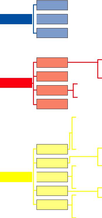
Right clicking with the mouse will bring up the Shortcut Menu which lets you access the Main Menu:
PICTURE 2.5-1
Menu items are divided by category. You’ll use the items in the Functions section most often. Items in the Settings area will allow you to set up your system exactly how you want it to operate and the Info section lets you monitor it. You can switch between items in the same category (i.e. switching to Event from Camera) from within the window without having to go back to the Main menu.
The “Menu Tree”, on the next page, is your roadmap to your system. Not all models have certain features, such as alarms. In such cases, the option for that feature won’t appear in the menu.
19
Search/
Playback
FUNCTIONS
 Backup
Shutdown
N I A M
U N E M
System
Event
INFO
Network
Log
Camera
Event
SETTINGS 
 Network
Storage
System
HDD
Record
BPS
Version
Online Users
Load
Test
Remote
Image
Camera Settings
Camera Name
Recording Schedule
Recording Status
PTZ
Detections
Alarm
Abnormality
Alarm Out
TCP/IP |
Block/Allow |
|
Ports |
||
PPPOE |
||
FTP |
||
DDNS |
||
POE Switch |
||
UPnP |
||
|
HDD Manage
Grouping
General
Display Default
Account Upgrade
Auto Maintain
Import/Export
20
2.6 PAN-TILT-ZOOM CAMERAS
AnalogHD Pan-Tilt-Zoom (PTZ) cameras are plug-and-play like other AnalogHD cameras. Unlike conventional PTZ cameras, they don’t require additional wiring as control signals are sent through the same wire that carries the camera’s video.
Because of their extra capabilities, they require additional setup to program their movements. These settings are found in the same window used to control the direction of the PTZ camera. The PTZ Control window can be reached through either the Navigation Bar (left) or Shortcut Menu (right).
PICTURE 2.6-1 |
PICTURE 2.6-2 |
BASIC CONTROLS
The PTZ camera is manually controlled using the mouse in the PTZ Control window. Clicking and holding an arrow in the Directional Controls will move the camera in that direction until the mouse is released or the physical limits of the camera is
reached (such as elevation).
PICTURE 2.6-3
An alternate way of directing the camera is with the mouse itself (QCN-series cameras only):
1.Click the Mouse icon to the immediate right of the Directional Controls.
2.The PTZ Control window will disappear.
3.Click and drag to point the camera where desired.
4.Right-clicking will return you to the PTZ Control window.
On cameras that support these features, the zoom, focus and iris (light level) can also be adjusted using the + and - buttons.
21
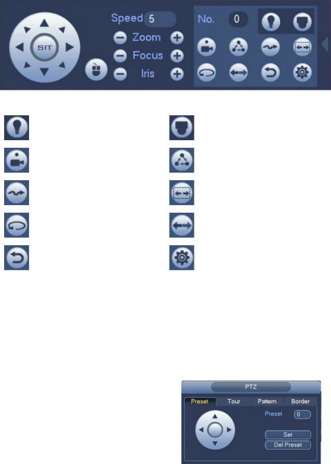
EXPANDED CONTROLS
Clicking on the arrow at the far right of the PTZ Control window reveals the expanded controls area which lets you command the camera to run a pre-programmed function.
PICTURE 2.6-4
|
|
Controls additional features |
|
|
Opens the camera’s |
|
Aux |
such as lamp or wipers. (If |
|
Menu |
internal on-screen menu (if |
|
|
available) |
|
|
available). |
|
|
|
|
|
|
|
Preset |
Moves camera to a pre-set |
|
Tour |
Camera will move to a |
|
Point |
point. |
|
sequence of pre-set points. |
|
|
|
|
|||
|
|
|
|
|
|
|
|
Camera will record your |
|
Auto- |
The camera will move |
|
Pattern |
movements and then follow |
|
horizontally between two |
|
|
|
Scan |
|||
|
|
that path. |
|
points. |
|
|
|
|
|
||
|
|
|
|
|
|
|
Auto- |
Camera will automatically |
|
Flip |
Flips video image. |
|
Pan |
continue to rotate 360° |
|
||
|
|
|
|
||
|
|
|
|
|
|
|
Stop/ |
Stops the camera’s current |
|
|
Set up and save Preset |
|
|
Config |
Points, Tours, Patterns and |
||
|
Reset |
action. |
|
||
|
|
|
borders for Auto Scan |
||
|
|
|
|
|
|
|
|
|
|
|
|
RUNNING PTZ FUNCTIONS
Enter the number of the action (tour, pattern, etc.) that you want the camera to run and then click the button for that action. The camera will follow that command until stopped using the Stop/Reset button or by a user taking direct control.
PROGRAMMING PTZ FUNCTIONS
Click the Config button to open up the Configuration window.
Preset Point
1.Enter a number for this point (1-80).
2.Move the camera to the desired point using the
Directional Controls.
3.Click Set.
4.Repeat for additional points.
5.Right-click to exit this window back to the PTZ Control window.
PICTURE 2.6-5
22

Tour
This is also known as a “Patrol”.
1. |
Enter the number (1-8) for this Tour (Patrol). |
|
2. |
Select the first Preset Point by entering its |
|
number. |
|
|
3. |
Click Add Preset. |
|
4. |
Enter additional points (up to 16) the same |
|
way). |
|
|
5. |
Right-click to exit this window back to the PTZ |
PICTURE 2.6-6 |
Control window. |
|
|
Pattern
The camera will record a pattern you create using the Directional Controls in real-time and will repeat it exactly when you run the pattern.
1.Enter the number (1-5) for this Pattern.
2.Move your camera to where you want to start the pattern.
3.Click Start to begin the recording. The camera will record each stop, the time spent at each point, the zoom, focus and other settings.
4.Click End when you have finished setting your pattern.
PICTURE 2.6-7
Border (Auto-Scan)
Use this to set the left and right end points for the camera to shift between during its Auto-Scan. The two points can be at different elevations, but the camera will only rotate in a straight line between these two points. If you need the camera to move to - or stop at - a third point, you should set up a Tour (above). There can be only one Auto-Scan path.
1.Move your camera to either the left or right point.
2.Click Left or Right and then move the camera to the other point.
3.Click the other button to select the end point.
• If you get your left and right points “backwards”
the camera will move between them, but facing |
PICTURE 2.6-8 |
|
the wrong way. |
||
|
||
• When you select Auto-Scan in the PTZ Control |
|
|
window, the camera will move between these |
|
|
two points until stopped. |
|
23

FUNCTIONS |
CHAPTER 3 |
This chapter covers the most commonly used, day-to- day features which are found in the Functions area at the top of the menu.
Subjects in this chapter: |
|
The Video Search and Playback Window. |
25 |
Searching for a recorded video. |
26 |
Locking a file to prevent deletion. |
27 |
Playing back recorded video. |
28 |
Saving recorded video. |
32 |
Back up some or all of your recorded videos. |
32 |
Shut down the DVR. |
34 |
 Loading...