

User Manual
QS494
QS458
QS4716
QS558
QS4816
QS Series DVRs
1
Thank You for Choosing a Q-See Product!
All of our products are backed by a conditional service warranty covering all hardware for 12
months from the date of purchase. Additionally, our products also come with a free exchange
policy that covers all manufacturing defects for one month from the date of purchase.
Permanent upgrading service is provided for the software and is available at www.Q-See.com.
Be certain to make the most of your warranty by completing the registration form online. In
addition to warranty and technical support benefits, you’ll receive notifications of product
updates along with free downloadable firmware updates for your DVR. Register today at
www.Q-See.com!
Please see the back of this manual for exclusions.
About this Manual
This manual is written for Q-See’s model QS494, QS458, QS4716, QS4816 and QS558 DVRs
and was accurate at the time it was completed. However, because of our ongoing effort to
constantly improve our products, additional features and functions may have been added
since that time and on-screen displays may change. We encourage you to visit our website at
www.Q-see.com to check for the latest firmware updates and product announcements.
Throughout the manual we have highlighted warnings and other important information that will
assist you in operating your new system in a safe and trouble-free manner. Please take the
time to read and follow all instructions and pay attention to alerts as shown below:
IMPORTANT! Red boxes with this icon indicate warnings. To prevent
possible injury or damage to the product, read all warnings before use.
NOTE! Text in blue boxes with the Information icon offer additional guidance
and explanations about how to make the most out of your system.
© 2012 Q-See. Reproduction in whole or in part without written permission is prohibited. All
rights reserved. This manual and software and hardware described herein, in whole or in part,
may not be reproduced, translated, or reduced to any machine-readable form without prior
written approval.
Trademarks: All brand names and products are trademarks or registered trademarks of their
respective owners.
Q-See is a registered trademark of DPS, Inc.
Disclaimer: The information in this document is subject to change without notice. The
manufacturer makes no representations or warranties, either express or implied, of any kind
with respect to completeness of its contents.
Manufacturer shall not be liable for any damages whatsoever from misuse of this product.
Rev. 3.1 8/19/12
2 3

TABLE OF CONTENTS
1. INTRODUCTION 7
Features And Specifications 8
2. INSTALLATION AND CONNECTION 10
Power 10
USB Ports 10
Video Display 10
Audio 11
QS494 12
QS458 14
QS4716 16
QS558 18
QS4816 20
3. CONTROLS 22
3.1 Mouse Control 22
Virtual Keyboard 23
3.2 Remote Control 24
4. BASIC OPERATION 26
4.1 Power On/Off 26
Standby Mode 26
Shutdown 26
4.2 System Login 27
4.3 Control Bar 27
4.4 Main Menu 28
4.5 Basic Menu 28
System 28
Date/Time 29
Display 29
Record 29
User 29
4.6 Recording 30
4.7 Playback 32
4.8 File Management 34
Locking and Unlocking Files 34
Backing Up Files 35
5. ADVANCED OPERATION 36
5.1 Basic Menu 36
Display 36
Users 37
5.2 Advance Menu 39
Network 41
Communication 41
P.T.Z. 41
5.3 Disk Management 42
Overwrite 42
5.4 Information 43
Device 43
Network 43
Online Users 44
Record 44
5.5 Maintenance 45
Basic 45
Settings 46
Logout 46
6. PAN-TILT-ZOOM CAMERAS 47
6.1 Connecting a PTZ Camera 47
6.2 Configuring and Controlling a PTZ Camera 49
Controlling the P.T.Z. Camera 50
Configuring Points and Cruises 50
7. HARD DISK DRIVE 52
7.1 Installation/Removal 52
7.2 Calculating the Recording Capacity of a Hard Disk Drive 54
APPENDIX 55
A.1 Troubleshooting 55
A.2 Product Specifications 56
Q-SEE PRODUCT WARRANTY 58
Questions or Comments? Contact Us 59
4 5
INTRODUCTION
To prevent damage to your Q-See product or injury to yourself or to others, read and
understand the following safety precautions in their entirety before installing or using this
equipment. Keep these safety instructions where all those who use the product will read them.
CHAPTER 1
WARNING! ELECTRIC SHOCK RISK!
nCheck the unit and any accessories included in the package immediately after opening. If
items are missing or damaged, repackage and return to the point of purchase.
n
Use the proper power source. Only use the power adapter supplied with your system. Do
not use this product with a power source that applies more than the specified voltage (100240V AC).
nNever insert anything metallic into the DVR. Inserting anything into the DVR or its case can
be a source of dangerous electric shock.
nDo not operate in dusty areas.
nDo not expose this product to rain or use near water. If this product accidentally gets wet,
unplug it and contact Q-See immediately.
nKeep product surfaces clean and dry. To clean the outside case of the DVR, gently wipe
using a lightly dampened cloth (only use water, do not use solvents).
nDo not operate this DVR without the cover securely in place. Do not attempt to do any
repairs to the DVR yourself. If there are unusual sounds or smells coming from the DVR,
unplug it immediately and contact Q-See technical support. Under no circumstances
should the cover be removed while the device is connected to a power source. You should
only remove the cover to install/replace the hard disk drive (See Chapter 7) or replace the
standard 3v lithium cell battery on the motherboard. These are the only user serviceable
parts. You may need to replace the battery if the internal clock resets itself after a power
outage
nHandle DVR box carefully. If you accidentally drop your DVR on any hard surface, it may
cause a malfunction. If the DVR doesn’t work properly due to physical damage, contact
Q-See for repair or exchange.
nMake sure there is proper air circulation around the unit. This DVR system uses a hard drive
for video storage which generates heat during operation. Do not block air holes located on
the bottom, top, sides and back of the DVR as they are designed to keep the system cool
while running. Install or place this product in an area where there is ample air circulation.
nProvide proper ventilation. This DVR has a built-in fan that properly ventilates the system.
Do not cover or impede this fan.
6 7

FEATURES AND SPECIFICATIONS
This product offers the following features:
Audio Recording
One channel of audio recording capability.
Smartphone Compatible
Access live footage directly from your iPhone, iPad as well as Android smartphones and
tablets. Your DVR can also be set to e-mail your hand held-device whenever specific activity
occurs, such as motion detection.
View Your Video Feed Online with No Extra Service Fees
View your DVR’s live or recorded video footage on any Internet accessible computer with
Internet Explorer, Mozilla Firefox and Google Chrome (using IE plug-in).
Stay Notified with Customizable Email Alerts
Set your system up to notify you when an event has occurred at the location you are
monitoring. Notification alerts can easily be adjusted to your specifications.
Advanced Motion Detection Activated Recording
Advanced motion detection settings ensure that false alarms are not triggered. The easy to
use motion detect set up screen allows you to mask out certain areas which experience heavy
movement in order to avoid false alarms and avoid unnecessary record triggering.
Multiple Backup Options
A built-in USB port gives you the option of backing up and transferring your video footage
using a flash drive or external USB hard drive. You can also connect to an external CD/
DVD writer to burn your file footage right onto a compact disc or DVD disc. Files can also be
accessed from your DVR system to a remote computer location by logging on remotely.
Connect to a TV or PC Monitor Easily
This system comes with both a VGA and BNC out port to allow you to connect to a TV or 19”
or larger VGA monitor for viewing purposes.
24/7 Scheduled Recording
Choose which days of the week and hours of the day you want to set your DVR to record or
not record.
Multiple Playback Options and Advanced Search Functions
Supports real-time CIF recording on each channel independently. Search through recorded
files while you are playing live footage, monitoring through a remote location using a supported
internet browsing application and backing up system files. A variety of playback modes
include: slow play, fast play, and backward play.
Network Monitoring
Supports network remote real-time monitoring (available bandwidth permitting), remote record
search and remote PTZ control.
Communication Ports
s RS485 port can be used for PTZ camera control.
s Standard Ethernet port allows you to access the DVR from a network or the Internet.
PTZ camera control
s Supports PTZ decoder via RS485.
s Supports the PelcoD and PelcoP protocols.
User-Friendly LCD Control Functions
Front panel button control allows instant booting up and system standby at the press of a
button. LCD monitor can be set to go into energy efficient stand-by mode.
Included Mouse and Remote Control
In addition to front panel button controls, system can also be booted up and put into standby
mode using the included remote control or mouse.
Storage Function
Encrypted file format to ensure data security and avoid vicious data modification.
Compression Format
Supports multiple-channel audio and video. Independent hardware decodes the audio and
video signal from each channel to maintain video and audio synchronization.
NOTE! Depending on your point of purchase, your DVR may have the hard
disk drive already installed. If your drive was packaged separately, or if you
wish to upgrade your installed drive up to a 2 Terabyte drive, please see
Chapter 7 at the back of this manual which covers installing hard drives.
8 9
INSTALLATION AND
CHAPTER 2
CONNECTION
Please note that it is important to keep in mind common safety guidelines when installing your
DVR or connecting additional devices – including turning off and unplugging your DVR before
installing internal components.
POWER
The DVR’s power supply plugs into the DC power socket on the back of the DVR. It is
absolutely essential that you only use the power supply that came with the DVR to ensure
proper operation and to avoid damage.
We also recommend that you use an uninterrupted power supply (UPS) so that the system will
continue to operate in the event of a power loss. In addition, you should connect the DVR into
a UL-1449 rated surge protector. It should have a joule rating of at least 400, a response time
of 10 nanoseconds or less and a clamping voltage of no more than 330 volts.
Your DVR will power up as soon as it is plugged in.
When shutting down the DVR, it is essential that you do so by using the Standby feature
within the software or the Standby button on the remote control. Once the display goes
blank, you may either turn off the surge protector or unplug the DVR.
If you wish to restart the DVR from standby mode, then you may do so by pressing and
holding the Standby button on the remote control.
USB PORTS
There are two USB ports on the rear panel of your DVR. Either may be used by the mouse
with the other port being used by a removable or externa USB drive for file backup and
firmware upgrades.
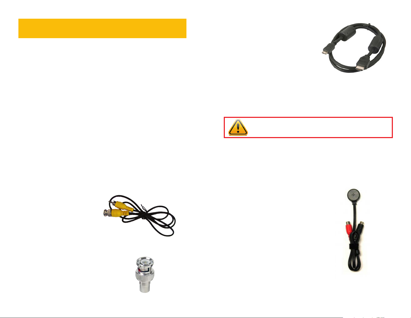
For DVRs featuring an HDMI® port on the
back panel, use the included HDMI® cable
(Picture 2-3) to connect to an HD monitor
or television.
PICTURE 2-3
It is possible to connect more than one displays to the DVR at the same time using the
different video ports, however they will all show the same images and they cannot be
combined. The menu and mouse cursor will appear on every display simultaneously.
IMPORTANT! The default resolution of this DVR is 1024 x 768 pixels. Some
monitors smaller than 19” may not display video properly.
AUDIO
Your system has one or more inputs to allow you to record sound to accompany the video
recording from a camera. This can be accomplished using either an audio-equipped camera
or a microphone co-located with the camera such as Q-See’s QSPMIC (Picture 2-4). The
RCA-style audio plug from the camera must be plugged into the correct port on the back of
the DVR in order for the sound to be recorded to the correct video track.
VIDEO DISPLAY
Depending on the model, your DVR can
output video to either a standard VGA
monitor, television or HD display. The monitor
is connected via a VGA monitor cable (not
included) to the VGA port on the rear of the
DVR. The television is connected to the BNC
Video Out port on the DVR’s back panel
through the use of the a BNC (Male) to RCA
(Female) adapter cable (Picture 2-1) which
is included with some models. This plugs into
the RCA Video In port on the back of the
television.
Another type of BNC to RCA adapter is
shown in Picture 2-2. This also attaches
to the DVR’s Video Out port but requires a
user-supplied standard RCA cable to connect
from it to the RCA Video In port on the back
of the television.
PICTURE 2-1
PICTURE 2-2
On DVRs with a single Audio In port, this
audio port will record sound to the first
camera only. Therefore, it is important to
make sure that the camera covering the area
of the microphone is also plugged into the
first Video In port. Systems with two Audio
In ports will record sound to Channels 1 and
2 only. If your DVR features multiple audio
input ports, they are numbered to correspond
with the channel of the same number.
PICTURE 2-4
10 11
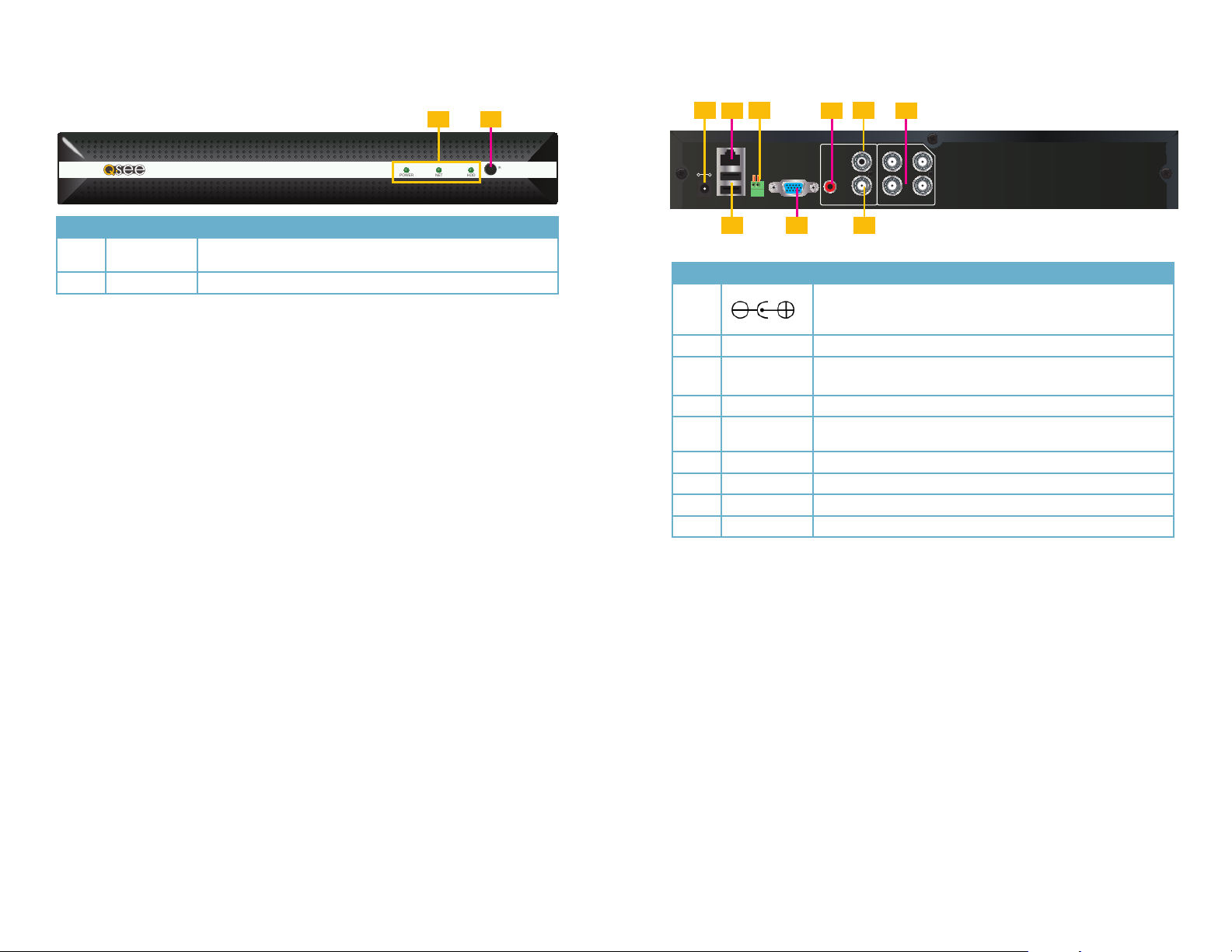
QS494
FRONT PANEL
REAR PANEL
4 Channels QS494
Item # Name/ Symbol Description
1 LED
INDICATORS
Shows status of hard drive, network, and whether the DVR is
currently recording.
2 IR SENSOR IR Receiver for remote control.
1 2
POWER NET HDD
1
IR
-
DC +12V
IN
3
2
RJ45
+
VGA
485A
485B
5
4 6
VIDEO IN
A-OUT
1 3
A-IN V-OUT
2 4
7 98
Item #
Connector Description
1
2 NETWORK For connecting Ethernet cable
3 RS485
4 AUDIO IN RCA audio input for connecting audio signal
AUDIO
5
OUTPUT
6 VIDEO IN 4 BNC video inputs for connecting analog video cameras
7 USB 2 USB ports for a mouse and external USB drive
8 VGA OUTPUT To connect to VGA monitor
9 VIDEO OUT Video output for connecting TV (BNC)
DC 12V/3A Power Connection
RS485 for connecting PTZ
485A is “Positive” and 485B is “Negative”
RCA connector for output to amplified speaker
12 13
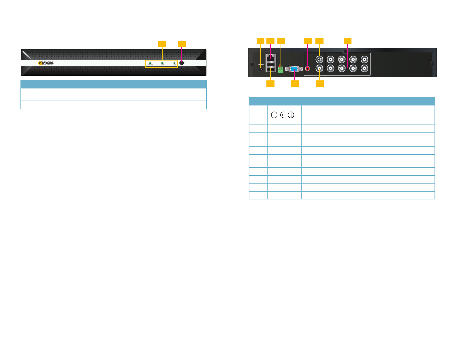
QS458
FRONT PANEL
REAR PANEL
4 Channels QS458
Item # Name/ Symbol Description
1 LED
INDICATORS
Shows status of hard drive, network, and whether the DVR is
currently recording.
2 IR SENSOR IR Receiver for remote control.
1 2
POWER NET HDD
1
IR
-
DC +12V
IN
3
2
RJ45
+
VGA
485A
485B
5
4 6
A-OUT
A-IN V-OUT
VIDEO IN
1 3 5 7
2 4 6 8
7 98
Item #
Connector Description
1
2 NETWORK For connecting Ethernet cable
3 RS485
4 AUDIO IN RCA audio input for connecting audio signal
AUDIO
5
OUTPUT
6 VIDEO IN 8 BNC video inputs for connecting analog video cameras
7 USB 2 USB ports for a mouse and external USB drive
8 VGA OUTPUT To connect to VGA monitor
9 VIDEO OUT Video output for connecting TV (BNC)
DC 12V/3A Power Connection
RS485 for connecting PTZ
485A is “Positive” and 485B is “Negative”
RCA connector for output to amplified speaker
14 15

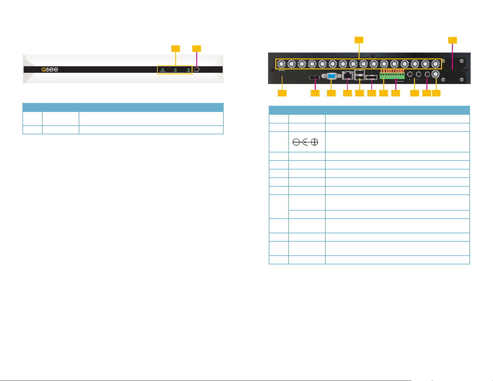
QS4716
FRONT PANEL
1 2
REAR PANEL
1
2
16 Channels QS4716
Item # Name/ Symbol Description
1 LED
INDICATORS
Shows status of hard drive, network, and whether the DVR is
currently recording.
2 IR SENSOR IR Receiver for remote control.
POWER NET HDD
IR
1 2 3 4 6 7 8 9 10 11 12 13 14 15 165
+
-
DC +12V
IN
VIDEO IN
1 2
AUDIO
1 2 3 4
NO
GND
VGA
RJ45 USB
GND
COM
485A
485B
ALM IN
IN
AUDIO
CVBS
OUT
OUT
3 54 76 9 118 10
Item #
Connector Description
1 VIDEO IN 16 BNC video inputs for connecting analog video cameras
2 FAN Cooling fan exhaust port. This should not be blocked.
3
4 VGA OUTPUT To connect to VGA monitor
5 NETWORK For connecting Ethernet cable
6 USB 2 USB ports for a mouse and external USB drive
7 RS485
ALARM INPUT 8 I/O Alarm input
8
ALARM
OUTPUT
9 AUDIO IN 2 RCA connectors for microphones
AUDIO
10
OUTPUT
11 VIDEO OUT Video output for connecting to TV (BNC)
DC 12V/3A Power Connection
RS485 for connecting PTZ
485A is “Positive” and 485B is “Negative”
I/O Output for alarm
RCA connector for output to amplified speaker
16 17
QS4816
FRONT PANEL
1 2
REAR PANEL
1
2
16 Channels QS4816
Item # Name/ Symbol Description
1 LED
INDICATORS
Shows status of hard drive, network, and whether the DVR is
currently recording.
2 IR SENSOR IR Receiver for remote control.
POWER NET HDD
IR
1 2 3 4 6 7 8 9 10 11 12 13 14 15 165
+
-
DC +12V
IN
VIDEO IN
VGAHDMI E-SATA
RJ45 USB
1 2
AUDIO
1 2 3 4
NO
GND
GND
COM
485A
485B
ALM IN
IN
AUDIO
CVBS
OUT
OUT
3 54 76 9 11 138 10 12
Item #
Connector Description
1 VIDEO IN 16 BNC video inputs for connecting analog video cameras
2 FAN Cooling fan exhaust port. This should not be blocked.
3
4 HDMI
®
5 VGA OUTPUT To connect to VGA monitor
6 NETWORK For connecting Ethernet cable
7 USB 2 USB ports for a mouse and external USB drive
8 E-SATA To connect to an external SATA drive.
RS485
9
ALARM INPUT 8 I/O Alarm input
ALARM
10
OUTPUT
11 AUDIO IN 2 RCA connectors for microphones
AUDIO
12
OUTPUT
13 VIDEO OUT Video output for connecting to TV (BNC)
DC 12V/3A Power Connection
To connect to a HD display
RS485 for connecting PTZ
485A is “Positive” and 485B is “Negative”
I/O Output for alarm
RCA connector for output to amplified speaker
18 19

QS558
FRONT PANEL
8 Channels QS558
1 2
POWER NET HDD
REAR PANEL
1 3
ON
DC +12V
IN
OFF
IR
21 3 4 6 7 85
AUDIO IN
1 2 3 4 5 6 7 8
VGAHDMI E-SATA
RJ45 USB
485A
GND
485B
1 2 3 4 5 6 7 8
NO
GND
COM
VIDEO IN
ALM IN
AUDIO
OUT
CVBS
OUT
42
5 76 98 11 1310 12 14
Item # Name/ Symbol Description
1 LED
INDICATORS
Shows status of hard drive, network, and whether the DVR is
currently recording.
2 IR SENSOR IR Receiver for remote control.
Item #
Connector Description
1 Power Switch Turn the DVR off after shutting it down from the Menu.
2 AUDIO IN 8 RCA connectors for microphones
3 VIDEO IN 8 BNC video inputs for connecting analog video cameras
4 FAN Cooling fan exhaust port. This should not be blocked.
5 DC 12V DC 12V/3A Power Connection
6 HDMI
®
To connect to a HD display
7 VGA OUTPUT To connect to VGA monitor
8 NETWORK For connecting Ethernet cable
9 USB 2 USB ports for a mouse and external USB drive
10 E-SATA To connect to an external SATA drive.
11 RS485
RS485 for connecting PTZ
485A is “Positive” and 485B is “Negative”
ALARM INPUT 8 I/O Alarm input
12
13
ALARM
OUTPUT
AUDIO
OUTPUT
I/O Output for alarm
RCA connector for output to amplified speaker
14 VIDEO OUT Video output for connecting to TV (BNC)
20 21

CONTROLS
This DVR can be controlled through the USB mouse or with the remote control. We have
found that the majority of our customers prefer to operate their DVRs using the USB mouse
because of its ease of use and flexibility and our manual is set up with this in mind. For your
convenience, we also include a remote control which allows you to perform most of the
day-to-day functions from a distance. It functions as a typical remote control with additional
buttons allowing you to navigate through menus and control functions. We recommend that
you configure your DVR using the mouse controls, reserving the remote control for operations
such as live viewing, file search and playback. For the purposes of this manual, instructions
will be given for using the mouse but the other modes are also presented in this chapter.
CHAPTER 3
3.1 MOUSE CONTROL
The mouse operates in a manner similar to how it is used on a conventional computer; pointand-click, right-click, double click and so on. How these functions are used is based on the
context of where they are used. Some examples are:
LEFT CLICK: Selecting an item
Opening a menu
Checking a box or motion detection status
Selecting letters, numbers or symbols on the virtual keyboard.
DOUBLE CLICK: Selecting an event for playback
Selecting a screen to zoom into from multi-screen mode
RIGHT CLICK Exits any window. Exits any menu or reopens previous menu.
Hides/reveals Control Bar
VIRTUAL KEYBOARD
The virtual keyboard is contextual. For example, it will only show digits when the field is for
numeral entries. In fields where letters and symbols can be entered, users can switch between
the two keyboards by using the Shift key.
Available keyboards include:
Numbers Only
Lower Case and Numbers
PICTURE 3-1
CLICK-AND-DRAG Select motion detection zone
Select privacy mask zone
The keyboards are used by clicking on the desired character. Characters are deleted with the
Backspace key. To finish entering your text, click the Enter key. To finish entering digits in the
Numbers Only keyboard, click the
Upper Case and Symbols
PICTURE 3-2
key. Clicking outside of the keyboard will close it.
22 23

3.2 REMOTE CONTROL
The buttons on the Remote Control operate in the same manner as on a conventional DVR
remote. Some buttons have multiple functions depending on which menu is being accessed.
# Name/Symbol Function
1 STANDBY Press to turn standby mode ON/OFF.
2 LOGIN/LOCK If “Security” has been enabled in the Setup menu,
press to open the user password login screen.
3 Number/Channel buttons While in menus, press buttons 0~9 to enter values;
during live viewing, press to view channels full-screen.
4
5 MENU Opens the main menu.
6 PTZ Press to open the PTZ control window.
7 EXIT Close menu windows.
8 Navigation/OK:
/CH+
/FWD
/REW
/CH-
OK In menus, press to confirm selections; during
9 +/ - : In menus, press to
adjust values.
10 RECORD: Press to start
manual recording.
11 STOP: Press to stop manual
recording.
12 EXTRA: For future use.
13 Playback controls:
Press to switch between quad and full-screen
displays.
Move cursor in menus up; Channel Up.
Move cursor in menus to the right
Move cursor in menus left
Move cursor in menus down; Channel down.
playback and preview, press to view system
information
Increase reverse playback speed 2X, 4X, 8X
Press to start playback
Press to increase forward playback speed 2X, 4X, 8X
Press to slow playback speed by 1/2, 1/4, 1/8
Press to freeze playback to one frame, then press
again to advance frame-by-frame
TIP: When using the remote
control to enter password and
camera titles, select the field
using the navigation buttons,
press ENTER, and then press
the number buttons.
PICTURE 3-3
24 25

BASIC OPERATION
This chapter is intended to help you get your DVR up and running before you activate any
advanced features which are covered in later chapters. You can use the mouse, remote
control and the buttons on the front of the DVR to operate your system, but for convenience,
we will be discussing operations using the mouse.
CHAPTER 4
4.1 POWER ON/OFF
Connect the power cable to the DC power port on the rear panel. It will power up when
connected to a power source.
At startup, the system performs a basic system check and runs an initial loading sequence.
After a few moments, the system loads a live display view.
STANDBY MODE
The system can be put into Standby Mode. Power will remain to the system but will not be
recording. This is done through the Maintenance window and will be covered at the end of
Chapter 5 you will need to push and hold the Standby button on the remote to resume use
of the DVR.
SHUTDOWN
When the DVR will not be in use for an extended period of time, it is recommended that you
shut it down completely. To do so, you will first need to put it into standby mode which is
located in the Maintenance menu. This will stop recording and idle the hard drive. Once the
DVR has gone into standby, turn off the power - preferably by turning off the surge protector
that it is plugged into.
4.2 SYSTEM LOGIN
By default, the DVR will display the live video from one or more cameras after starting up. In
order to access the features, including playback of recorded video, you will need to log into
the system.
The Login window will appear whenever a
user attempts to access the DVR while not
being currently logged in - whether to an
extended period of inactivity or by having
previously logged out.
By default, passwords are disabled on
the system. You do not need to enter a
password when accessing any system
menus. This is done as a convenience to
assist in setting up your system.
The default user name is admin and the password is blank (no password). Just click
Apply Once you have completed setting up your DVR, it is highly recommended to enable
passwords on the system using the Password menu in order to secure your system.
PICTURE 4-1
4.3 CONTROL BAR
The Control Bar gives direct access to many of the system’s functions, features and options
without having to go through a series of intermediate steps. It appears at the bottom of the
screen and can be hidden or revealed by right-clicking the mouse. It will disappear when a
menu is opened and reappear after all menus are closed.
IMPORTANT! To protect your system, you should always power down the
DVR as described above before unplugging it or using the power switch.
PICTURE 4-2
Start Opens the Main
Menu
Single
Screen
MultiChannel
View(s)
Color
Adjust
Select a single
channel to view
View multiple
channels on-screen
at the same time.
The number of
options varies by
model.
Adjust the
appearance of the
video on the screen.
This does not affect
the recorded video.
Digital
Zoom
Volume Adjust volume
PTZ
Controls
Record Starts and stops
Playback Opens the video
Digitally enlarge a
section of the video
(requires audio
source)
Opens PTZ camera
controls
manual recording
search and
playback window
26 27

4.4 MAIN MENU
To access the Main Menu, click on the Start button in the Control Bar. If the Control Bar is
not present, right-clicking on the screen will make it appear.
The Main Menu is the primary means of accessing the full set of functions of the DVR. This
is in addition to the shortcuts to specific features through the Control Bar. Right clicking with
the mouse will close the Main Menu window and return to the Live View mode.
PICTURE 4-3
4.5 BASIC MENU
As its name implies, this is where most of the basic settings are made to configure your DVR
to your needs. The Setup Wizard made many of these automatically and you were asked
to fill out certain fields, such as date and time during that process. You can adjust or add to
these settings within the various submenus shown on the left side of the Basic menu.
You will need to click on Apply to save your changes in each submenu. Right-clicking will
close the window without preserving your changes, as will clicking on the Exit button. Default
will restore factory settings only to the submenu that you are currently in.
DATE/TIME
There are two tabs in this submenu.
Date/Time
This tab allows you to set the date and
time along with the format you wish both
to be displayed. You can chose between a
traditional 12-hour clock, or a 24-hour version
(commonly referred to as military time).
If you did not select your time zone during the Startup Wizard process, you may do so now. If
you are uncertain of your time zone, you can find it at http://www.worldtimezone.com
Synchronization allows you to use an Internet time server to keep your DVR’s internal clock
accurate, much in the way that your computer uses one. Use of this feature requires that the
DVR is connected to the Internet.
DST
Use this tab to configure your DVR to
automatically adjust for Daylight Savings Time
if your region uses it.
You are able to set the start and end dates
based on whether the time changes on a
specific date or on a certain week within a
month. For example, as of this writing, DST
begins on the second Sunday of March and
ends on the first Sunday of November in
most parts of the U.S. and Canada.
PICTURE 4-5
PICTURE 4-6
You must click Enable to activate this feature.
SYSTEM
This area allows you to name your DVR
(useful in situations where you own more than
one), adjust the resolution and format, set
your desired language and when - or whether
- the DVR will log you out due to inactivity.
If the Startup Wizard is not set to Off, you
should change it to that status at this time to
avoid having to go through it when the DVR
restarts.
PICTURE 4-4
If you are in North America, you should not change your video format from the NTSC
standard. Other regions, including Europe, along with Brazil, Argentina and Uruguay in South
America use the PAL format. Video mode does not make a difference if you are using a VGA
monitor.
The DVR will take a moment to switch languages if you chose to change.
DISPLAY
This menu will be discussed in detail in the
next chapter, but you may chose to name
your cameras in a manner more convenient
to you at this time.
PICTURE 4-7
RECORD
Your DVR is factory set to record when motion is detected. Adjusting your recording method
an schedule is discussed in Section 4.6 Recording immediately following.
USER
Adding, editing and deleting user accounts will be covered in Chapter 5.
28 29

4.6 RECORDING
The fundamental purpose of your DVR is to view live cameras as well as to record events as
they happen. This section covers how to configure the settings to best suit your requirements.
Since each user’s needs are different, we will provide information on the options available
which you may combine as you need.
Basic Tab
By default, your DVR is configured to record
when motion is detected. Each camera is
enabled as is audio recording. Audio tracks
will only be added to the video if you have
microphones or audio-enabled cameras
connected to your DVR.
The recording mode is set for Schedule which allows it to follow the schedule set up under
that tab (discussed below). The other option is to enable the cameras to record all the time.
You can copy settings in this tab from one camera to another using the Copy button. Be
certain to click Apply to save any settings you make in this tab.
Bit Rate Tab
This tab controls the quality of the video recorded by the cameras. The resolution, frame rate
and physical quality of the recordings may all be adjusted. The factory settings are optimized
to best balance quality with the amount of space required to store recorded videos.
PICTURE 4-8
Schedule Tab
As stated earlier in this section, your DVR is configured to record when motion is detected
24/7. The Schedule tab reflects this with the weekly schedule filled completely with red
signifying that it is set to record on Alarm. This schedule setting not only saves disk space,
but makes it easier to locate recordings of events when they do occur because there is much
less video that needs to be searched through.
The different recording modes are color coded:
Manual
Normal
Alarm
You can alter the schedule, including the type
of recording mode, by selecting the desired
mode and then clicking and dragging in the
desired area of the schedule with the mouse.
The area will fill with the color indicating the
recording mode for that time.
Mistakes can be corrected by selecting a
different recording mode and changing the
block of time back to the desired mode.
DVR will not record unless user begins it by clicking on the Record
button in the Control Bar or on the remote control
DVR records continuously
DVR will only record when motion is detected
PICTURE 4-10
Resolution - D1 resolution is 704x480 pixels
Framerate - Smooth, “real-time” video
footage moves at 30 frames per second
(fps). A lower frame rate generates jerkier
movement, but it requires less disk space.
PICTURE 4-9
Quality - This ranges from “Normal” to “Best” with increasing levels of image clarity. Each
improved level requires more storage space on the hard drive.
You may copy the Bit Rate settings from one camera to others. Simply select which camera
to use as the source and which camera(s) to apply the settings to and then click on the Copy
button.
In Picture 4-11 at right, the DVR has been
set to record continuously (green) during the
period of time between 8am and 5pm (1700
hours) on Tuesdays with the exception of the
12 noon and 1pm (1300 hours) which has
been set to Manual (black). The rest of the
time, the schedule is set so that the DVR will
record when an event is detected (red).
Each camera is configured separately, but you may copy the schedule from one channel to
another by selecting the camera with the desired schedule as well as which camera - or all
cameras - to which you want to apply the schedule. Click Copy and the other cameras will
have the same schedule.
For more precise schedule setting, you may
double-click on a day’s bar and a Schedule
pop-up window will appear allowing you to
set the recording mode along with the start
and end times. Add or delete scheduled
blocks using the appropriate button.
PICTURE 4-11
PICTURE 4-12
30 31

4.7 PLAYBACK
Once your DVR records video, the next step is search for - and play back - specific events.
There are two methods available to play back files. Clicking on the Playback arrow at the
far right of the Control Bar will begin playback of the day’s recordings. However, if you are
looking for files recorded on a different day, or want to find a specific recording, clicking on the
Search icon in the Main menu will open the Video Search window.
Video Search
The Video Search window provides a pair of
options to retrieve files for viewing.
The calendar will highlight the current date in
blue and will use red to highlight other days
that contain video recordings.
PICTURE 4-13
Clicking on Playback will cause the DVR to start playing back all the recorded files from that
day beginning with the earliest one recorded. If more than one camera has video, the multichannel views will show the playback from each camera in synch with the playback from
others.
You may also narrow your search by selecting the hours to search between as well as the
type of recording - Regular or Alarm using the pull downs under the calendar. Additionally,
you may limit your search to only select cameras.
Once you’ve set your options, you may double-click on the date in the calendar or on the
Search button below it to reveal a list of video files in the right side portion of the window that
match your criteria. Each listing will show the starting and end times, the type of recording and
whether the file has been locked to prevent erasure. Only a limited number of files will appear
at a time. Click on Prev., Next, Last or First to navigate through the “pages” of files. Double-
click on the desired file to begin playback which will occur in a new window.
Playback Shortcut
Clicking on the arrow at the far right of the Control Bar will open the Playback window and the
system will begin playing the first video(s) recorded that day.
1 3
2 4
5 76 8 9 10 11 12 13 15 16 1714
PICTURE 4-14
No. Item Function
1 Calendar Select the date to search
2 Time Scale Shows the time videos were recorded on each channel
3 Playback Progress
Fence
4 Files Red areas indicate files triggered by events.
5 Increase/Decrease
Time Scale
6 Recorded time Shows when the currently playing file was recorded
7 Minimize/Maximize Clicking this will hide or reveal the Time Scale and Calendar
8 Fast Rewind Plays video backwards at normal or 2, 4, or 8x speed
9 Play/Pause Pauses and restarts playback
10 Frame Advance Moves playback forward one frame
11 Slow Advance Plays video forward at 1/2, 1/4 or 1/8 speed
12 Fast Advance Plays video forwards at 2, 4, or 8x speed
13 Digital Zoom Zoom into a video
14 Volume Will only affect channels with recorded audio
15 Hide Playback
Controls
16 Minimize/Maximize Clicking this will hide or reveal the Time Scale and Calendar
17 Close Playback Ends playback and returns to Video Search window or Live
Shows location of playback within the records. This may be
moved forward or back.
Green areas are files that were recorded when the channel was
set to regular.
Zooms Time Scale to allow more precise selection of video files
while leaving the playback controls on screen.
Hides Playback Controls, Calendar and Time Scale. Right
clicking will reveal them.
while leaving the playback controls on screen.
View depending on the method used to launch the Playback
Window
32 33

4.8 FILE MANAGEMENT
When you record an important event, you will want to ensure that it does not get erased by
accident. You will likely also want to back it up onto another device where it can be shared
with others, including law enforcement if need be. Managing your files takes place in the same
Record Search window as used for locating files for playback.
LOCKING AND UNLOCKING FILES
Your DVR is configured to overwrite old files when the hard drive is full. While you have the
option to disable this feature, it means that your DVR will stop recording new video when the
drive reaches capacity. Depending on the size of your hard drive, and the amount and size of
your recordings, it will generally take at least several days to a month before your drive is full.
In order to preserve important files on your drive and to prevent them from being overwritten,
you may lock them. When a file is locked, it can also not be erased accidentally. It must be
unlocked before it can be deleted. Please note that if the hard drive is erased or reformatted
ALL files will be deleted regardless of whether they were locked.
When you perform a file search using the Search button below the Calendar as described in
the previous section, a list of files conforming to your search criteria will appear in the right side
of the window.
You can double-click on a file to play it
back in order to verify that it is the desired
recording and then right-click to return to the
list.
To lock this, or other files, click in the check
box to the left of the file name. Click Lock
and the file’s status will change to Locked.
To unlock a file, simply repeat the process,
checking the box to the left, and click
Unlock. The file will not be deleted, but will
be overwritten as the DVR records new files.
PICTURE 4-15
BACKING UP FILES
File backup is handled much in the same way as selecting files for playback and is done
through the Record Search window. There are two methods available; backing up all files
recorded within a given day, and backing up only selected files.
No matter which method, backing up files requires that a USB drive - either removable flash
USB or external USB hard drive - to be connected to the USB port on the rear panel of the
DVR that is not being used by the mouse.
Files will be saved into a folder entitled RecordFiles and will be saved in the .avi format.
This common file type is usable on both Macintosh and Windows PCs using readily-available
playback software, including Windows Media Player, QuickTime, DiVX and others.
File names will be saved with a long file name showing channel, date, start time and duration
such as: CH01-20120607-075719-000125.avi.
The first set of characters is the channel name - Channel 1.
The second group is the date - 6/7/2012.
The third group of numbers is the start time - 07:57:19 AM.
The last set of digits is the length of the recording - 1 minute, 25 seconds.
Back Up All Files for a Date
To back up all files recorded on a certain
date, make sure that a USB drive is
connected to the back of the DVR.
Click on the desired date on the Calendar
and then click on the Backup button below
the Calendar. A status window will open
asking you to wait as the files are backed up.
You may remove the drive after the window
indicates that the transfer is complete.
Backing up Select Files
This operates in the same manner as searching for files to lock. Connect a USB drive
Select the date and, if desired, a range of time to search.
Click on Search to create a list of files in the right portion of the window.
Put a check mark in the box to the left of the desired files.
Click on the Backup button below the list to start the transfer. A window will open to confirm
that files are being transferred. You may remove the USB drive after the window says that the
backup is complete.
PICTURE 4-16
34 35

ADVANCED OPERATION
The previous chapters covered information needed to help you set up and operate the
essential functions of your DVR. This chapter will provide information covering more advanced
features to enable you to get the most out of your system.
To allow you to easily locate information about a feature, they will be listed in the order they
appear within the menus. Most of the features within the Basic and Search menus were
covered in the previous chapter so please refer to that section of the manual for information
on the Recording, Playback, File Management, and Basic configuration. Information on
connecting ad operating PTZ cameras will be included in its own chapter.
CHAPTER 5
Color
You can adjust the appearance of your
camera’s feed on your monitor using these
controls. It will not effect the video that’s
recorded onto your hard drive.
5.1 BASIC MENU
Most of the features within this menu were covered in Chapter 4 with the exception of
display settings and user management which will be covered below.
DISPLAY
Camera Name
As mentioned earlier, you can rename your
cameras to a more convenient title, such as
the location of the camera, should you wish,
by clicking in the name field for a camera and
then using the Virtual Keyboard to enter the
new name.
PICTURE 5-1
Mask
This allows you to block off, or mask an area of the camera’s view. This could be to hide an
access keypad, or combination, for example. Masked areas will not be shown on the live view
or in the recorded video file.
Select the Settings button under Mask for the channel you wish to mask. You will see a live
view from that camera. Click and drag over the area you wish to block out. You may mask up
to four areas.
Click Apply to save your areas. Clicking
Clear will remove all masks from that
channel. You can switch to another camera
within this menu or return back to the Basic
menu.
PICTURE 5-2
Overlay
You can adjust the position of the channel
name and time stamp on your live feed and
recorded video. You may also turn off either
or both using this interface.
Click on the Settings button below Overlay
for the camera you wish to modify.
You can turn off the time stamp and channel
name individually by unchecking their box.
You may also click and drag the displays to
a new position. Clicking Default will restore
them back to their original location.
USERS
Your system comes with one administrator account already set up. If you will be the only
person operating this system, you will only need this one as it has been configured to have
permission to access and control every function and feature on the DVR.
IMPORTANT! To ensure the security of your system, you should create a
password for your admin account at this time.!
Setting Admin Password
The admin account does not come with a
password so it is up to you to create one.
Simply double-click on the admin account
name and a window will open up allowing
you to enter the password. Enter it twice and
click Apply to set it. Your password should be
something you can easily recall. If you write
it down, store it in a location away from the
DVR.
PICTURE 5-3
PICTURE 5-4
PICTURE 5-5
36 37

Adding, Editing and Deleting Users
If you wish to allow someone else to use your system, it is recommended that you give them
their own user account. You can have a total of five user accounts, including the admin
account - which is the only administrator-level account permitted. The admin account may not
be edited or deleted, but you can limit other user accounts to what they can or cannot see,
control or change on the DVR. You may only change user permissions while logged into the
admin account.
To add an account, click on Add user.
5.2 ADVANCE MENU
The settings within this menu cover how your camera interacts with the world around it - what
events are triggered when it detects motion, or how you can access it remotely.
ALARM
Your system considers events such as motion detection, drive failure and video signal loss to
be alarms.
Motion
This is the default method used by the
DVR to record events and these settings
do not need to be altered in most cases.
However, certain situations will require
some modification to avoid issues such as
excessive alarms.
PICTURE 5-6
Enter the user name and password for your
new account.
Binding Mac Client is used to limit remote
access by a user to a specific computer. This
is generally reserved for advanced users. You
will need to determine the MAC address of
the computer that will be used, and enter that
address in the field provided.
PICTURE 5-7
Once you’ve created a new user account,
you can restrict what options that user is able
to access. For instance, you can allow one
user the ability to only view live feeds from
specific cameras, while giving another user
authority to view all the cameras and play
recorded video, but not allowing either the
permission to change the recording mode or
schedule.
PICTURE 5-8
Click Apply to save your new account and permissions.
To edit an account, simply double-click on its name in the list of users while logged in as
admin and make your settings. Be certain to click Apply in order to save your changes.
A camera will record when the Enable box
next to it is checked.
Sensitivity can be adjusted to determine how much motion will cause recording to begin. The
sensitivity ranges from 1 (most sensitive) to 8 (least sensitive). Reducing sensitivity can lower
the number of false alarms caused by swarming insects, for example.
You are also able to turn off motion detection in certain areas of a camera’s view using the
Area setting.
Clicking on Settings will bring up a live view
from the chosen camera overlaid by a grid of
green boxes. Clicking and dragging will turn
boxes gray, disabling motion detection.
Clicking a gray box will return it to green.
Right-Click to exit.
In the case of Picture 5-10, recording will not be triggered when someone walks down the
hall at the bottom of the stairs, but recording will be triggered if someone climbs them.
You can also use masking to block out items such as flags or busy roads to prevent false
alarms.
PICTURE 5-9
PICTURE 5-10
To delete an account, check the box next to it in the list and then click on Delete.
38 39

The Schedule function is similar to the one used to set up the recording schedule (covered
in Section 4.6 Recording), but this controls the alarm response only. You can set the alarm
to be on or off during specific periods. These responses are set up in the next option, Trigger,
and control what actions the DVR will take when motion is detected.
Video Loss
If the DVR detects the loss of video feed from a camera, it can trigger other actions, just as
with the Alarm menu.
An example of setting an alarm schedule
would be to turn off the audible alarm and
pop-up message for the period that you are
away from the DVR to avoid calling attention
to it.
PICTURE 5-11
Like the Recording Schedule, doubleclicking on a day in the Alarm Schedule
timeline opens a pop-up window allowing you
to make more precise settings.
PICTURE 5-12
In addition to recording when an event takes place, the DVR can also activate, or trigger, other
actions. Among these options are an audible buzzer alarm from the DVR itself, sending out
e-mail, and beginning recording on other channels. These actions are set in the Trigger area
of the Alarm menu.
Record - You can have other camera’s begin
recording even if they did not detect motion.
Snapshot - This is a still image captured by
one or more cameras. These can be attached
to any alarm e-mail.
Alarm Output - The length of time that the
DVR will remain in its “alarm state”.
Buzzer - The length of time that the audible
alarm will sound.
Pop-up Image - When triggered, the selected cameras live feed will appear in full-screen
mode.
Post- and Pre-Record - The amount of time that will be recorded by the camera detecting
the event before and after it occurs.
P.T.Z. - If you have a Pan-Tilt-Zoom camera connected to the DVR, you can have it rotate to a
preset point or begin a pre-programmed cruise. Please see Chapter 6 P.T.Z. Cameras for
instructions on utilizing a PTZ camera with your DVR.
PICTURE 5-13
Camera Block
If the DVR determines that a camera is being blocked, it can also trigger a response in the
same manner as the Alarm or Video Loss functions. This function is normally disabled but it
may be turned on for individual cameras should your situation require it.
Because certain environmental factors,
such as a door that is open during business
hours, can block a camera, you are able to
adjust the sensitivity and set a schedule to
turn off camera blocking as needed. Or, you
can disable the function completely, if need.
The schedule and trigger functions work as
previously described.
PICTURE 5-14
NETWORK
Most of the settings in this menu were made using the Startup Wizard during your initial setup.
This chapter is covered in the Remote Monitoring Guide that came on the CD included
with your DVR. It is also available for download at Q-See.com/Support
COMMUNICATION
As with Network, this menu is covered in the Remote Monitoring Guide.
P.T.Z.
Pan-Tilt-Zoom cameras will be discussed in Chapter 6 P.T.Z. Cameras.
40 41

5.3 DISK MANAGEMENT
This menu allows you to manage and monitor the hard drive(s) mounted within your DVR. You
can check drive capacity, set overwrite status and format a new or existing hard drive.
Clicking on this menu from the Main menu
will show the status of any hard drives
mounted in your system. It will show the
current capacity and available free space.
PICTURE 5-15
You are also able to format any mounted hard drive by selecting the Format box next to the
desired drive and then clicking on the Format button. Please see Chapter 7 for instructions
on mounting or replacing a hard disk drive.
5.4 INFORMATION
As its name implies, the sole purpose of this menu is to provide information about the status
of various aspects of the DVR. With the exception of online users, you will not be able to
change anything using this menu.
DEVICE
This window shows the serial number, version
of firmware (the software that runs the DVR)
and the MAC ID of your system. The Device
Name and Device ID may be set in the
System menu and the MAC ID is set by your
network.
PICTURE 5-17
NETWORK
Consisting of two tabs, this menu shows your network status.
CAUTION! Formatting the hard drive erases all video data! This step cannot
be undone!
OVERWRITE
Like any computer hard drive, saving files - in this case video recordings - will eventually fill
it to capacity. When the drive is full, no more files can be written to it and recording will stop.
For that reason, the DVR is configured to overwrite older files when it is full. Depending on
your settings, drive size and the number of recordings, this can be as soon as a week to a
month. You can lock critical recordings in the Search menu as shown in Section 4.8 File
Management. This means that the DVR will record around them until you unlock them.
Another option is to set the DVR to overwrite after a certain number of days. Select this option
from the pull-down and then set the desired maximum number of days (up to 99). You will
need to use the “C” key in the Virtual Keyboard to clear the current settings. Be aware that if
your drive fills up before that time, your DVR may stop recording.
PICTURE 5-16
LAN
This shows the status of your local area
connection (LAN), which is your business or
home network centered around your router.
The IP address shown at the bottom is the
address used to access your DVR remotely
from the Internet (WAN).
PICTURE 5-18
PPPoE
If your DVR is connected directly to your
Internet Service Provider (ISP) through a
modem, then this window will contain the
information regarding your connection. You
will need to get this information directly
from your ISP and enter it according to the
instructions in the Remote Monitoring
Guide.
If you have a more conventional connection through a router, the information windows will be
empty.
PICTURE 5-19
42 43

ONLINE USERS
This shows the users who are connected
remotely to the DVR, along with their log-in
time and IP address. You can disconnect a
user from the DVR temporarily by clicking the
red box to the right of their name.
To block a user permanently, you will need to
adjust their privileges in the User menu (see
Section 5.1).
PICTURE 5-20
5.5 MAINTENANCE
The options in this menu allow you to update your DVR, restart it, keep it operating at top
condition and restore your favorite settings.
BASIC
Auto Maintain
Like a typical computer, your DVR operates
at its best if it is restarted every so often. This
allows it to clear out temporary files and other
useless bits of data that can cause it to slow
down.
RECORD
Data regarding the recording quality of your
cameras is shown here. The column on the
far right is useful in calculating how big a file
your recording settings will generate. If disk
space is a concern, you can adjust your
settings in the Record menu (see Section
4.6 Recording).
PICTURE 5-21
Using the pull-down, you can set the DVR to
restart monthly, weekly or daily. You are able
to further define the restart time and day in
the other fields.
Firmware Upgrade
Also like a typical computer, we release occasional firmware updates to address issues or
improve functionality. These updates are available for free through our Help Site at Q-See.
com/Support where they can be downloaded onto your computer and transferred to an empty
USB drive which is then placed in the USB port not used by the mouse.
With the USB drive in the port, click on Firmware upgrade. The DVR will ask you to confirm
before upgrading. After your system has been upgraded, it will restart.
Standby
Standby is a soft power off for the DVR. If Standby is selected, and confirmed, the system will
stop recording and shut down. This is the preferred method used to turn off the DVR rather
than turning it off at the power switch. Once the DVR has shut down, then you may unplug it
or turn off the surge protector.
To exit standby mode, you will either need to press and hold the Standby button on the
remote, or restart the machine.
Reboot
This simply causes the DVR to shutdown and restart automatically.
PICTURE 5-22
44 45

SETTINGS
Unlike computers, the DVR does not store its operating system (firmware) on the hard drive,
but instead it stores it on the mother board so your settings will be retained even if you switch
hard drives. You are able to backup your settings onto a USB drive much like a video file. This
is useful if you are experimenting with optimizing your settings and do not want to start over
from the factory defaults if you do not like the results.
You are also able to restore the factory
defaults using this menu.
PICTURE 5-23
LOGOUT
It is recommended that you log out from your
DVR when you will be away from it for an
extended period of time - especially if others
have access to your system.
This will not shut down the DVR, but merely
require that a user log back in to control the
system.
PICTURE 5-23
PAN-TILT-ZOOM CAMERAS
CHAPTER 6
6.1 CONNECTING A PTZ CAMERA
Some QS-Series DVRs can support one or more Pan/Tilt/Zoom, or PTZ cameras. These
cameras connect to the DVR through the same ports as a conventional camera, but the
control wires connect through the RS485 block on the back of the DVR. Picture 6-1, below,
is only a representation and your actual connector may look different. Please consult Chapter
2 Installation and Connection to find the diagram representing your model for the
location of your connector block.
The RS485 connector uses a single-direction protocol meaning that it can send commands
out to the camera(s) but not receive any data back from the unit. Video images will be
delivered through the video cable as with any other camera.
The DVR is set by default for RS485 to be disabled for each channel. Therefore, PTZ settings
must be enabled before PTZ cameras can be utilized. This system supports 26 of the most
common protocols including Pelco-D and Pelco-P.
When connecting a PTZ camera, the following should be taken into account:
• The 485 port of this DVR cannot parallel connect with the 485 port of another device
• The voltage between the A and B lines of the camera should be less than 5V.
RS-485
STEP 1. The data cable from the PTZ
camera must be connected to
the ports highlighted in Picture
6-1. Multiple PTZ cameras can be
connected to this port, but you may
require an expander port to do so.
STEP 2. Connect the other end of
the cable to the proper pins in the
connector on the camera
STEP 3. Connect the camera video and
power cables as you would any other
camera.
1
NO C
2
NO C
CNTRL
12V
1 2 3 4 5 6 7 8
PICTURE 6-1
A B
STEP 4. Go to the P.T.Z menu within
the Advance menu.
STEP 5. Choose the correct
communication protocol, address
and baud rate. See your camera’s
manual, if needed.
STEP 6. Click Apply.
PICTURE 6-2
46 47

PTZ Definitions and Descriptions:
Parameter Settings What it Means
Address 1-255 The address of the PTZ camera
Preset Points 1-255 Programmed positions that the camera will point to.
Points 1-99 may be configured by the user
Baud Rate 1200-9600 The speed that data is transmitted
A lower speed may be needed for longer cable runs
Protocol The communication protocol used by the camera.
Supported protocols are; Pelco-D, Pelco-P, PelcoD1,
PelcoD2, PelcoD3, PelcoD4, PelcoP_WJ, ABK2001, ACESHN, Dragon, EE, HT600, HY, Lilin, Philips, SAE, Samsung,
YAAN, YLDVR
6.2 CONFIGURING AND CONTROLLING A PTZ CAMERA
All activities regarding controlling the PTZ camera manually, or setting up automatic cruises,
take place in the PTZ control panel located in the Control Bar.
PICTURE 6-3
1
2
3
4
5
6
9
10
11
12
13
14
15
7
16
8
PICTURE 6-4
No. Item Function
1 Channel Select which channel the PTZ is connected to.
2 Light Turns on camera’s light (if so equipped)
3 Wiper Turns on camera’s wiper (if so equipped)
4 Iris controls Adjusts light levels
5 Focus controls Adjusts focus
6 Zoom Zoom in or out
7 Directional
Controls
8 Speed Adjust speed of camera’s movement
9 Preset Choose the Preset Point number.
10 Set Preset Sets camera’s current position as preset point indicated by the
11 Clean Deletes preset point
12 Call Goes to preset point
13 Cruise Line Selects a cruise for the camera to follow
14 Start Begins cruise
15 Stop Stops cruise
16 Cruise settings Click to build cruise from preset points.
Click on arrows to move camera in desired direction.
number to the left.
48 49

CONTROLLING THE PTZ CAMERA
Once the PTZ Control Panel is open, you can direct the camera by selecting its channel and
using the directional controls. Click and hold to move the camera in the desired direction.
You can adjust the speed of movement using the slider. The Iris, Focus and Zoom controls
are paired to either side and allow you to adjust the image by increasing or decreasing their
respective functions. Some cameras feature automatic iris and focus controls and those
buttons will not affect that camera. Similarly, the Wiper and Light buttons will not work on
cameras without those features.
Creating a Cruise
STEP 1. Click on the Cruise Settings button
to open the Cruise Settings window.
STEP 2. Click on the Settings button net to
the correct channel.
PICTURE 6-6
If the PTZ camera will only be manually controlled, then you may wish to change the recording
mode and schedule for manual recording only as every time the camera moves, the DVR will
treat that as motion detection.
CONFIGURING POINTS AND CRUISES
In addition to being manually controlled, you can configure your camera to follow a set path,
pointing from location to location and repeating. In this mode, you should change your alarm
settings, if not your recording mode and schedule. Each time the camera moves, it will trigger
a motion detection event. It is recommended that you set the channel to record continuously
and turn off any alarm activity associated with that channel.
STEP 3. Select which number cruise this will
be. You may also give it a custom name.
STEP 4. Click on the green + button on the
left to begin adding preset points to the list.
PICTURE 6-7
STEP 5. In addition to selecting the Preset
point, you may also select the speed at
which the camera will move along with how
long it will stay pointed at that point before
moving on to the next point.
STEP 6. Click OK to add this point to the list.
PICTURE 6-8
STEP 7. Repeat Steps 4-6 as needed to add
more points. The camera will return to the
first point after stopping at all the points on
the list and the cruise will begin again.
To remove a point, select the check box to
the left and click on the red X button.
PICTURE 6-5
Creating Preset Points
STEP 1. Point the camera to the desired spot. Adjust focus, iris and zoom as necessary.
STEP 2. Set the Preset pull-down to the desired number (1-99) and then click Set.
STEP 3. Move the camera to the next desired spot and repeat to create the next preset.
STEP 8. When complete, click on the green
button to save.
To test your cruise, return to the PTZ controls, select your Cruise line and press Start. You
can edit your cruise at any time by changing Preset points as well as adding or deleting points
from the list.
PICTURE 6-9
50 51

HARD DISK DRIVE
CHAPTER 7
Your DVR uses an A/V Rated 7200RPM 3.5” SATA (Serial Advanced Technology Attachment)
hard disk drive and will support drives up to 2TB (terabytes). These drives are the current
industry standard and may be purchased wherever computer parts are sold. Depending on
where you purchased your DVR, your hard drive may already be installed. But, we recognize
that you may wish to upgrade or replace your drive in the future so this DVR is designed
to make installation and replacement easy for the average user. A 5400RPM drive will be
adequate as long as it is A/V Rated, but a 7200RPM drive is recommended for optimal
performance.
STEP 4. Connect the power and data
cables. Press firmly, but do not
force them onto the pins or you may
damage them. The connectors are
“keyed” to ensure they are connected
in the proper position.
STEP 5. Attach hard drive to the base of
the DVR with screws using the four
mounting holes.
HARD DRIVE
HARD DRIVE
It should be noted that while this is the only user-serviceable part within the case besides the
battery and you will not void your warranty by installing or upgrading your hard disk drive, care
must be taken to avoid damage to the other components within the case. Such damage will
not be covered.
WARNING! ELECTRIC SHOCK RISK!
The DVR MUST be unplugged from all power sources as well as from
the cameras before opening the case. Failure to do so can result in
damage to the DVR or its components as well as injury or death.
7.1 INSTALLATION/REMOVAL
It is strongly advised against opening the case when atmospheric conditions present the risk
of static discharge which can damage electronic components.
Whether installing the drive for the first time or removing the old one to install a new one, the
steps are largely the same:
STEP 1. Disconnect the DVR from the power source as well as any other connections.
STEP 2. Remove screws (the number will vary depending on your model) from the side
and rear of your DVR
Holes for
Holes for
Hard Disk Drive
STEP 3. Remove the case by sliding it
backwards and then lifting off.
STEP 3A. If removing a hard drive, you
will need to unscrew the four drive
mounting screws at the bottom of the
DVR or on the internal mounting rack.
Hard Disk Drive
Mounting Screws
Mounting Screws
STEP 6. Replace the DVR cover and
secure.
MOUNTING HOLES
FOR HARD DRIVE
PICTURE 7-2
DATA
CABLE
POWER
CABLE
PICTURE 7-1
52 53

7.2 CALCULATING THE RECORDING CAPACITY OF A
HARD DISK DRIVE
While the physical data capacity of a hard drive is fixed, how much video you can record upon
it depends on your recording configurations. Higher quality recordings will take up more space
on the drive and setting the DVR to record for more frequently will fill it up more rapidly.
To determine the optimal capacity for your purposes, the chart below to estimate the size of
hard drive that you’ll need.
VIDEO
FORMAT
NTSC CIF 30 Highest 1000k 465
PAL CIF 25 Highest 1000k 466
RESOLUTION FRAME
RATE
(FPS)
D1 7.5 Highest 500k 228
D1 7.5 Highest 500k 228
VIDEO
QUALITY
Higher 768k 297
Medium 512k 230
Low 384k 173
Lower 256k 115
Lowest 128k 56
Higher 375k 128
Medium 250k 117
Lower 192k 75
Lowest 128k 61
Higher 768k 295
Medium 512k 235
Low 384k 175
Lower 256k 112
Lowest 128k 56.4
Higher 375k 128
Medium 250k 117
Lower 192k 75
Lowest 128k 61
BIT
RATE
(kbps)
SPACE
USED
(MB/h)
APPENDIX
A.1 TROUBLESHOOTING
1. The DVR does not start after connecting the power, what is wrong?
a. The power adapter may have been damaged, or is not providing enough power. Please
change the adapter.
b. The DVR may not be getting enough power from the outlet or surge protector it is
attached to.
c. There could be a problem with the system board on the DVR
2. The indicator lights of the DVR are on, but no output. Why?
a. The power adapter may have been damaged, or is not providing enough power. Please
change the adapter
b. The video format of the DVR is different from that of the monitor.
c. Connection problem. Please check the cable and the ports of the monitor and DVR.
3. Why are no images displayed on some or all of the channels of the DVR?
a. Connection problem. Please check the cables and the ports of camera and DVR.
b. Camera problem. Please check the cameras by attaching them directly to TV or working
port on DVR.
c. The video format (NTSC/PAL) of the DVR is different from that of the cameras. Please
change DVR video format.
4. The DVR cannot find the hard disk drive.
a. The power adapter is not providing enough power, or the adapter is not getting enough
power from the outlet
b. Connection problem. Please check the power and data cables on the HDD.
c. The HDD is damaged and will need to be replaced.
5. I cannot record, what could be the problem?
a. The HDD is not formatted. Please format it manually first.
b. The record function is not enabled or setup correctly. Please refer to Section 4.6
Recording.
c. The HDD is full and the Overwrite function is not enabled. Please refer to Section 5.3
Disk Management.
d. The HDD is damaged and will need to be replaced.
6. I cannot use the mouse, what could be the problem?
a. Wait 5 minutes after connecting the mouse and then try again.
b. The mouse is not securely connected. Plug/unplug several times.
c. The mouse is incompatible with the system. Please try another mouse.
The formula for calculating the required disk space is:
Total Recording Capacity = Used space per hour (MB/h) x Recording time (hour) x
number of channels
Example: A customer is using the NTSC format (30 frames per second), CIF resolution
with video quality set to Lowest and a total of 16 Channels. He wants the unit to record
continuously for a month. Therefore, the calculation will look like this:
56(MB/h), x 24 (hours/day) x 30 (days) x 16 (channels) = 645,120MB or 650GB
Installing a 750GB SATA hard drive should provide enough space for one month’s continuous
recording time at those settings.
54 55

A.2 PRODUCT SPECIFICATIONS
ITEM DEVICE
PARAMETER
SYSTEM LANGUAGE English, French, Portuguese, Spanish
VIDEO VIDEO IN 4 ch. 8 ch. 16 ch. 8 ch. 16 ch.
VIDEO OUT 1 ch. Composite video output, BNC, VGA
VGA OUTPUT 1024x768, 1280x1024
VIDEO DISPLAY 1 or 4 ch.
VIDEO
STANDARD
AUDIO AUDIO INPUT 1 ch. 1 ch. 2 ch. 8 ch. 2 ch.
AUDIO OUTPUT 1 channel, impedance 600Ω, RCA
RECORD STYLE Audio and video recorded simultaneously
AUDIO
COMPRESSION
PICTURE
PROCESSING
AND
STORAGE
PICTURE
COMPRESSION
PICTURE
RESOLUTION
STREAMING
STYLE
AUDIO STYLE ADPCM
VIDEO CODE
RATE
AUDIO CODE
RATE
DATA STORAGE 1 SATA HDD UP TO 2TB
QS494 QS458 QS4716 QS558 QS4816
Composite video input 1.0VP-P, impedance 75Ω, BNC
1V P-P CVBS signal
switch,
quad
display
CIF PAL, 25F/S, CCIR625LINE, 50SCENE
CIF NTSC, 30F/S, CCIR525LINE, 60SCENE
CIF 30fps
D1 30fps
Impedance 600Ω, RCA
8khz 16bit ADPCM
H.264
CIF (352x240) D1 (702x480)
ISO14496-10
CIF: 384~768 KBPS D1: 896-1280 KBPS
32KB/S
SPECIFICATION
1, 4 or
9 ch.
switch,
quad
display
CIF 30fps
D1 6fps
1, 4, 9
or 16 ch.
switch,
quad
display
CIF 30fps D1 30fps CIF
1, 4 or
9 ch.
switch,
quad
display
1, 4, 9
or 16 ch.
switch,
quad
display
30fps
D1 30fps
ITEM DEVICE
PARAMETER
ALARM ALARM INPUT N/A N/A 8 8 4
ALARM I/O VOLTAGE N/A N/A 5v 5v 5v
CONNECTOR ALARM
Backup USB
2.0
SOFTWARE
UPGRADE
OTHERS VOLTAGE INPUT AC:110~240V
OUTPUT
PTZ INTERFACE SUPPORT 1 RS485 (Pelco-D, Pelco-P, PelcoD1,
NETWORK
INTERFACE
USB Mouse USB 1.1
SUPPORTS
USB FIRMWARE
UPGRADE
VOLTAGE
OUTPUT
POWER
CONSUMPTION
WORKING
TEMPERATURE
QS494 QS458 QS4716 QS558 QS4816
N/A N/A 1 1 1
PelcoD2, PelcoD3, PelcoD4, PelcoP_WJ, ABK2001,
ACES-HN, Dragon, EE, HT600, HY, Lilin, Philips, SAE,
Samsung, YAAN, YLDVR)
RJ45, 10M/100M
Yes
Yes
DC: 12V@2A DC:
7W without HDD
50 TO 104°F (10 TO 40C)
SPECIFICATION
12V@3A
DC:
12V@2A
DC:
12V@2A
56 57

Q-SEE PRODUCT WARRANTY
Q-See is proud to back all of our products with a conditional service warranty covering all
hardware for 12 months from the date of purchase. Additionally, our products also come with
a free exchange policy that covers all manufacturing defects for one month from the date of
purchase. Permanent upgrading service is provided for the software.
Liability Exclusions:
Any product malfunction or abnormalities in operation or damage caused by the following
reasons are not within the free service scope of our company:
1. Equipment damage caused by improper operation.
2. Improper equipment operation environment and conditions (e.g., improper power,
extreme environmental temperatures, humidity, lightning and sudden surges of
electricity).
3. Damage caused by acts of nature (e.g., earthquake, fire, etc).
4. Equipment damage caused by the maintenance of personnel not authorized by Q-See.
5. Product sold over 12 months ago.
In order to fulfill the terms of your warranty, you must complete the registration process after
purchasing our product. To do this, simply fill out the User’s Information Card on our website
at www.Q-See.com
QUESTIONS OR COMMENTS? CONTACT US
PRODUCT SUPPORT, DOWNLOADS,
FIRMWARE UPDATES & MANUALS
24/7 Technical Resources
Live Chat (M-F, 9-5 PST)
www.Q-See.com/Support
58 59

Digital Peripheral Solutions, Inc.
8015 E. Crystal Drive
Anaheim, CA 92807
60
 Loading...